631 Sign Lighting
Documentation Requirements – 630/631 Traffic Signs and Sign Supports
General
Sign lighting is not necessary for overhead guide signs when Type H or J reflective sheeting is used for the reflective legends. Therefore, for new installations, sign lighting will normally not be used.
Guidelines and design information on sign lighting are addressed in TEM Sections 212 and 240-7.
This section provides additional information about what to look for when installing sign lighting.
1. Check certified shop drawings, catalog cuts, etc. for luminaires, ballasts, switches and enclosures.
2. Luminaires for mercury vapor sign lighting shall comply with 731.01 and shall consist of a housing containing a reflector, lamp socket, wiring and a door containing a glass lens or refractor, meeting the following requirements:
a. The housing shall be adequately reinforced cast aluminum with a natural finish or painted gray.
b. The reflector shall be highly reflective aluminum.
c. The lamp socket shall be a porcelain shrouded mogul screw with lamp grips and a large center spring providing firm contact with a lamp base.
d. The door shall be an aluminum frame either cast with a natural finish or a formed extrusion with an anodized finish. The door shall be hinged securely to the housing and provided with a spring loaded latch. Hinges shall be stainless steel and designed so that unintentional door separation is impossible. Latches shall be stainless steel and are not to require tools for opening.
e. A flexible readily removable gasket shall be attached to the housing or door so a waterproof seal is formed when the door is closed and the gasket compressed. The glass lens shall be mounted within the door and sealed with elastic cement or a gasket.
f. The glass lens shall be borosilicate or equivalent, able to withstand hail or the thermal shock of freezing rain.
g. Drainage weep holes shall be provided in the housing or door depending upon the luminaire’s bottom or top position on a sign.
3. Mercury vapor lamp sizes shall be as specified. Ballast type shall match the specified lamp wattage. Lamp watts and ANSI code are shown in TEM Table 297-11 and SCD TC-31.21.
4. Sign lighting shall be controlled by a disconnect switch within an enclosure. The switch shall be a two-pole minimum, single throw, fused safety disconnect type rated at 600 volts and 30 amperes (C&MS Item 631.06). The fuse size shall be as specified. A solid neutral bar shall be provided.
5. The enclosure shall be weatherproof and lockable, complying with NEMA standard Type 4 ICS 1-110.15. Enclosure size shall be as specified (See SCD TC-32.10).
6. Each enclosure shall be furnished with at least one padlock. Padlocks shall have a corrosion resistant body and a corrosion proof steel shackle. All padlocks for a project are to be keyed alike from an appropriate master key number obtained by the contractor from the maintaining agency.
7. Sign service to the enclosure shall be in accordance with the plans. Service wiring cable size shall be as specified, single conductor rated at 600 volts and not less than Number 4 AWG (631.04). Sign service underground from a pull box to a foundation mounted support, or to a support mounted on a concrete median barrier, is shown on SCD TC-32.10. Sign service from a direct drop is shown on SCD TC-32.11.
8. Sign wiring from the disconnect to the luminaires shall be the size specified, single conductor rated at 600 volts and not less than Number 10 AWG (631.05). The wiring shall be fully protected within enclosures, support interiors, junction boxes, rigid or flexible conduit and luminaire housings. Wiring shall be continuous from the disconnect switch to a junction box mounted on the sign support or overpass structure. The junction box shall permit disconnection of wiring when a sign and its lighting equipment is removed as a unit. A junction box shall be installed for each sign. Wiring shall be continuous from the junction box to the first luminaire on a sign and continuous between additional luminaires on the sign.
9. Luminaire ballast shall be located within the luminaire (integral) or in a weatherproof housing attached to or beside the luminaire (contiguous). Wiring to the ballast shall be continuous with permitted disconnection at the sign support junction box (see paragraph 8).
10. The wiring routing for wired signs shall be as shown on SCD TC-31.21.
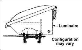
11. Luminaire supports complying with SCD TC-31.21 are specified for new installations. Support arms are of welded tubular design incorporating an attachment flange and a luminaire support plate. The arms are bolted to a continuous rectangular galvanized steel tube forming the lower portion of the sign’s glare shield. The face of the rectangular tube shall be covered with non-reflective sheeting complying with 730.20 so as to match the color of the glare shield sheeting. Support arms shall not be mounted upside down or in any other manner than that permitted by the SCD.
12. Luminaires shall be adjusted to a proper aiming angle according to the manufacturer’s instructions and inspected at night to determine if they are providing uniform illumination to the sign face.
Sign Lighting Inspection and Testing
1. In accordance with 631.11, sign lighting and electrical signs shall meet the requirements of the following tests as required by 625.19 and performed by the contractor:
a. Ground rod resistance to ground (see 632).
b. Cable insulation (Megger) test (see 632).
c. Ten-day performance test (see 632).
2. During the ten-day performance test, failure of lamps, ballasts and transformers may be corrected by replacement of the faulty component but will not require restart of the entire test period.
3. The contractor should perform a circuit test on all sign lighting cable and wire conductors to determine if there are any short circuits, cross circuits or other improper connections. Circuit testing may be done in accordance with 632 .
4. The test results shall be reported to the project engineer in the test information required by 625.19. The test results should be documented.
5. During the ten-day performance test, a night inspection shall be performed by the contractor and final adjustments made to sign lateral positions and the aiming angle of luminaires to the satisfaction of the project engineer (631.11). The adjustments are to eliminate excessive brightness and glare and to obtain optimum sign face reflected brightness, uniformity of illumination, visibility and legibility.
6. Following successful completion of a ten-day performance test and after there has been a partial or final acceptance of the project, the contractor should turn over to the project engineer all manuals, diagrams, instructions, guarantees and related material. The project engineer should transfer the material to the maintaining agency. For ODOT-maintained signs, the material should be given to the appropriate ODOT District Office.
7. After the project has been accepted by ODOT, the project engineer should immediately notify the maintaining agency that as of a certain exact time and date, the agency is responsible for the maintenance.
Documentation Requirements – 630 / 631 Traffic Signs and Sign Supports
1. Ensure signs and supports are in compliance with plans and approved catalog sheets
2. Document depth, diameter, or foundations
3. Document steel and clearance maintained (if used)
4. Document support stubs (if placed)
5. Document anchors - diameter and depth (if used)
6. Document size and depth driven of drive post used
7. Document curing used on concrete
8. Measure appropriate units for foundations and/or supports used and turn in for pay
9. Document type, size, background sheeting and legend sheeting for signs
10. Measure signs and turn in for pay as per 630.14