507 Bearing Piles
Description (507.01)
A pile is a structural column
of steel, concrete, timber, etc. that is installed in the ground to support a
structure above it. Piles are required
when the soil near the surface is not strong enough to support the structure or
when the soil may be scoured away. Piles
transfer the loads from the structure to deep layers of soil or rock that are
capable of supporting the load.
The term, “bearing pile,”
refers to a pile that is used to support a structure. A bearing pile is also
called a service pile or a production pile.
The plans include a
foundation layout which identifies each pile with a unique number and indicates
the pile type, size, and direction of batter (if any). Use the unique number to identify the pile in
the construction documentation.
General (507.02)
There are many types of
piles; however, the Department generally uses either cast-in-place reinforced
concrete piles or steel H-piles that are driven into the soil using an impact
hammer. The cast-in-place piles are
constructed by driving a hollow steel tube, capped at the bottom with a steel
plate, into the ground, and then filling the tube with concrete.
The plans give the estimated
length for each pile. However, the
Contractor decides whether to drive a single pile segment for the entire
estimated length or to drive shorter segments and splice them together as he
drives the pile into the ground.
Materials (507.03)
The steel for H-piles must
conform to 711.03
which refers to ASTM A 572,
Grade 50 (Fy=50 ksi). This is the industry
standard for H-piles. The steel pipe for
cast-in-place piles must conform 711.07
which refers to ASTM A 27 Grade 65-35 or Grade 70-36 or AASHTO
M103 or ASTM A 148 Grade
90-60.
Driving of Piles (507.04)
Piles are typically driven to
a specified capacity (Ultimate Bearing Value) or to refusal on bedrock. The Ultimate Bearing Value, or UBV, is equivalent to the ultimate pile capacity (in
Allowable Stress Design) and the nominal pile resistance (in LRFD). The UBV is the
required capacity of the pile. Sometimes the plans list the design bearing, the
design load, or the factored load in addition to, or in place of, the UBV. Do not mistake
the design load for the capacity to which the piles are to be driven.
Typically, H-piles are used
when piles are driven to refusal on bedrock, and cast-in-place piles are used
when piles are driven to a specified capacity.
However, H-piles are sometimes used when driving to a specified
capacity.
In some cases, such as
bridges over water, where scour may be a concern, the plans may indicate a
minimum pile tip elevation in addition to the UBV. If both a UBV and a
minimum pile tip elevation are specified for the piles, both criteria must be
met. If the pile is driven to the
required tip elevation before reaching the UBV,
continue driving until the pile has the required capacity. If the pile is driven to the UBV before reaching the minimum pile tip elevation,
continue driving until the pile tip is at the required elevation.
If during the driving
operation the pile begins to crush, the driving operation must immediately
cease and the crushed section of the pile removed. This is due to the fact that the crushed
section will behave similar to a sponge and the energy from the pile hammer
will no longer be properly transmitted to the tip of the pile. This results in higher blow counts with
minimal penetration of the pile into the ground.
Piles Driving Longer or Shorter than
Estimated
In the event a pile reaches
150 percent or more of the estimated depth without achieving capacity or in the
event of a pile reaching capacity in less than 80 percent of the estimated
depth, about two more piles should be driven in scattered locations to verify
this trend. If these piles also exceed
the above limits, contact the Office
of Construction Administration or the Office
of Geotechnical Engineering for advice.
You may also contact the District Geotechnical Engineer for advice. Complete information regarding equipment, the
driving logs, and any unusual driving experiences should be provided for review. During this review, the Contractor may be
permitted to continue his driving operation.
However, the Contractor should not be required to attempt to drive the
piles to 80 percent of the estimated penetration. He should also not cut the piling off until
after the review.
Occasionally, when bearing is
achieved before the pile has been driven 80 percent of the estimated
penetration, project personnel require the Contractor to continue driving the
pile to achieve a penetration of 80 percent of the estimated depth. This is not recommended. The value of 80 percent of the estimated
penetration is only a guide to aid project personnel. Overdriving the pile may result in damage to
the pile or the pile hammer. Do not
require the Contractor to overdrive the pile to obtain the 80 percent length
without first consulting with the Office
of Construction Administration, the Office
of Geotechnical Engineering, or the District Geotechnical Engineer.
Pile Driving Equipment
A driving cap that centers
the pile under the hammer and uniformly transmits the blow must be used.
Driving leads guide the
travel of the hammer and cap during driving and must be capable of keeping the
hammer in line with the axis of the pile.
The leads should be equipped with a yoke at the base to center the pile
and project beyond for anchorage.
Pile Hammers
Pile hammers are powered by
compressed air, hydraulic oil pressure, or igniting diesel fuel. These hammers are classified as either
single-acting hammers or double-acting hammers.
In addition to power driven
hammers, a drop hammer may be used which has a ram weight of at least 3,000
pounds (1,360.8 kg) and a distance of fall not exceeding 7 feet (2.1 m).
Single-acting hammers are
those that have their rams lifted by compressed air, hydraulic oil pressure, or
igniting diesel fuel. When the ram reaches
the top of its stroke, it falls back to its original position by gravity. Hammers that are powered by igniting diesel
fuel and open on the top are considered open-end diesel hammers. These hammers
allow the ram to become exposed during driving.
Double-acting hammers are
those that not only have the ram lifted by compressed air, hydraulic oil
pressure, or igniting diesel fuel, but in addition to gravity, compressed air
or hydraulic oil pressure also impart a downward force on the ram.
Double-acting hammers that
are diesel powered and are closed at the top are considered closed-end diesel
hammers. The space between the top of
the ram and the top of the hammer casing is called the bounce chamber. As the ram rises in the hammer, the volume of
the bounce chamber decreases and increases the pressure of the air inside the
bounce chamber. This increased air pressure imparts a downward force on the
ram.
Hammer Size
The Contractor chooses the
size of the hammer to use. The hammer
must be sized to the UBV of the piles. Typically contractors in Ohio use an open
ended diesel hammer with a rated energy in the range of 40 to 45 kip-ft., but
may be different. A hammer that is too
small will not be able to drive the pile to the required UBV.
A hammer that is too big may result in pile damage and may increase the risk of
alignment difficulties.
The hammer must be large
enough to drive the pile to the required UBV and
successfully perform dynamic load testing. The use of a hammer that is too
small will result in a hammer that will not be large enough to impact the piles
with enough energy to successfully perform a dynamic load test. Dynamic load testing cannot determine the
total capacity of the pile being driven if the energy applied to the pile by
the pile hammer is too low. An example
of this situation is the case where a cast-in-place pile has been driven to the
top of a hard layer of sand and gravel that may be capable of supporting a load
of over 300 tons. If the maximum load
that the pile hammer is able to place on the pile is only 120 tons, then the
dynamic pile test will only register 120 tons and not 300 tons. If the required UBV
is 120 tons or less, then the hammer is large enough. However, if the required UBV is greater than 120 tons, then the pile hammer is not
large enough to successfully perform a dynamic load test. Note: This is a
simple example to demonstrate the concept. The actual relationship between
hammer energy and pile capacity is much more complex.
Performance of the Pile Hammer
The driving criteria or blow
count that a pile must be driven to depends on the performance of the pile
hammer. If the
performance of the hammer changes, then the appropriate driving criteria will
also change. Therefore, the
performance of the hammer should be constantly observed. The performance of the hammer should be
compared with the results of the dynamic load testing to determine the required
blow count. The Contractor is required to provide the Inspector with a means to
monitor this operation.
Open-end diesel hammers are
the most common type of pile hammer for highway contractors in Ohio. A relatively easy way to monitor the
performance of an open-end diesel hammer is to watch the stroke of the ram. During the dynamic load testing, watch how
far the rings on the ram come out of the hammer. Then, during pile driving, make sure that the
rings are coming out of the hammer about the same distance. The ram of an
open-end diesel hammer falls by gravity; therefore, the stroke of an open-end
diesel hammer can be estimated from the blow rate (blows per minute) using the
following equation.

Where:
h =
Stroke of pile hammer (feet)
bpm = Blows per minute
(From Design and Construction of Driven Pile
Foundations, FHWA NHI-05-043, pages 21-28)
For convenience, the
following table gives the results of the above equation for a typical range of
values. Additionally, the relationship
between stroke and blows per minute for a particular pile hammer can be
determined from the dynamic load test.
|
Blows per Minute |
Stroke (ft) |
|
Blows per Minute |
Stroke (ft) |
|
37 |
10.2 |
|
42 |
7.9 |
|
38 |
9.7 |
|
44 |
7.2 |
|
39 |
9.2 |
|
46 |
6.5 |
|
40 |
8.7 |
|
48 |
6.0 |
|
41 |
8.3 |
|
50 |
5.5 |
Trying to count the blows per
minute while also keeping track of the blows per foot is difficult. An easier way to determine the blows per
minute while counting the blows per foot during pile driving is to measure the
number of seconds required to drive one foot of piling. Use the following equation to calculate the
blows per minute.
![]()
Closed-end diesel hammers
must be equipped with a gauge placed on the ground and connected to the bounce
chamber by a hose. The gauge shows the
pressure developed for each stroke of the ram.
A graph, included with the gauge, can be used to convert the pressure to
the energy developed by the hammer for each blow. The hose connecting the gauge to the bounce
chamber comes in different lengths that can affect the reading on the
gauge. Therefore, it is important to
check that the graph corresponds with the length of hose used.
The Contractor can control
the hammer’s operating energy by the use of a throttle or fuel setting. The hammer must be operated during pile driving
at the same setting used when the dynamic load test was performed.
Alignment in Leads
If the hammer is not properly
aligned with the pile, the energy from the hammer will not be properly
transmitted to the pile. For the full
effect of the hammer energy to be transmitted to penetration of the pile, the
axis of the hammer must be in line with the axis of the pile.
Determination of Required Driving Criteria (507.05)
The driving criteria, or
required blow count, is determined from the dynamic load test results. See Section 523. The first two piles are driven with the
dynamic load test equipment attached.
The testing company should provide a preliminary recommendation for the
driving criteria immediately after driving these two piles. The driving criteria will be a minimum blows
per foot for the pile driving. For
open-end diesel hammers, the driving criteria will also include a minimum
hammer stroke.
Drive the rest of the piles
to the recommended driving criteria.
Generally, it is not necessary to ensure the pile has a blow count
greater than the required blow count for 3 or more consecutive feet. For example, if the required blow count is 43
blows per foot, it is not necessary to drive the pile until the blow count is
greater than 43 for 3 consecutive feet.
See the following table for examples.
The exceptions to this are if there is a minimum pile tip elevation, the
depth of penetration is less than 80 percent of the estimate, or the pile has
to be struck with 150 blows to inspect a splice.
Pile Driving Examples
Required Blow Count is 43 blows/ft
|
Penetration |
Blows/Ft |
|
Penetration |
Blows/Ft |
|
37-38 |
28 |
|
41-42 |
21 |
|
38-39 |
33 |
|
42-43 |
40 |
|
39-40 |
42 |
|
43-44 |
40 |
|
40-41 |
45 |
Should stop |
44-45 |
43 |
|
41-42 |
43 |
driving here. |
45-46 |
44 |
|
42-43 |
41 |
|
46-47 |
48 |
|
43-44 |
43 |
|
47-48 |
41 |
|
44-45 |
44 |
|
48-49 |
46 |
|
45-46 |
46 |
|
49-50 |
50 |
Cast-In-Place Reinforced Concrete Piles (507.06)
A cast-in-place reinforced
concrete pile consists of a steel shell that is filled with concrete. To minimize the possibility of the piles
being damaged during the pile driving operation, it is important to maintain
the minimum wall thickness specified in 507.06
of the Construction and Material Specifications.
Piles may be tapered or of
uniform section. The tapered piles are
cylinder shells with vertical fluting or corrugations commonly referred to as monotube piles. Monotube piles can be either tapered or of a uniform
diameter. All other piles of uniform section are called pipe piles. Tapered monotube
point sections come equipped with a bullet-nosed tip. Pipe piles usually have a plate welded on the
point that must not extend more than 1/4 inch (6 mm) beyond the surface of the
pile at any point. The Engineer should
ensure that the cast-in-place metal shell is of domestic origin and it conforms
to ASTM 252A 27 Grade
65-35 or Grade 70-36 or AASHTO M103 or ASTM A 148
Grade 90-60. A producing mill
certification is often the simplest way to verify this.
The piles must be inspected
and necessary measurements made. Due to
the possibility of lateral earth pressure causing adjacent piles to collapse
prior to filling with concrete, this inspection and measurement should be made
after all the adjacent piles are driven.
After the piles are driven, cover the tops until they are filled with
concrete. Before filing with concrete,
remove water and debris. Concrete
required for filling the piles is Class QC 1 containing a superplasticizer
admixture. After the superplasticizer
has been added, the slump should range from 6 to 8 inches (150 mm to 200
mm). The concrete should be deposited in
a steady, small stream to ensure complete filling and consolidation. If there is reinforcing steel in piles, the concrete
could become segregated from coming into contact with the reinforcing steel
while it is dropping in place. Use drop
chutes to eliminate this problem. No
driving shall be performed within 15 feet (4.6 m) of filled piles until the
concrete has cured at least 7 days.
Steel H-piles (507.07)
When H-piles are specified,
the plans usually require that they be driven to refusal on bedrock. The standard plan note gives a driving
criterion of 20 blows per inch. The note
may allow the Contractor to perform a dynamic load test, at his own expense, to
determine the driving criteria instead of using the 20 blows per inch
criterion.
When the bedrock is hard and unweathered, refusal is obtained after the piles contact
bedrock and have been struck at least 20 more times, with a penetration less
than or equal to 1 inch (25 mm), to ensure that firm contact has been
established. Use care to avoid damaging
the piles.
When the bedrock is soft or
weathered, driving refusal is obtained at a resistance of 20 blows per 1 inch
(25 mm).
Many times pile points or
pile shoes are specified to be welded to the tip of the piles. These points or shoes are made of cast steel
as opposed to plates welded together and are used to protect the end of the
pile from damage during the driving operation.
Mill test reports are
required for steel H-piles and should be reviewed by the Engineer for
conformance to 711.03
of the Construction and Material Specifications. If pile points or shoes are specified, mill
tests should be reviewed for conformance to 711.07
Timber Piles (507.08)
Although still included in
the specifications, timber piles are no longer used by the Department.
Splices (507.09)
Splicing may be necessary to
provide the required length to achieve bearing.
Numerous splices using small lengths in the same pile should be avoided,
particularly in an area exposed to view.
Splices should be made at least 3 feet above the ground so that the weld
may be observed while it is subjected to the impacts from the pile hammer. If bearing is obtained prior to observing the
weld during 3 feet of driving, the pile should still be driven a minimum of 150
blows after the splice is made in order to observe the weld. When splicing structural shapes (H-piles),
welding must be performed in accordance with 513.21
of the Construction and Material Specifications, which, among other things,
requires the use of a prequalified welder.
See Figure 507.A - Joint Preparation for Groove-Welded H Pile for the
method of making the required welded butt splice. For H-piles, the plans may include a note
that allows the use of a manufactured splicer in place of the full penetration
butt weld.
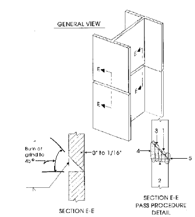
Figure 507.A
– Joint Preparation for Groove-Welded H-Pile
Note: If a different number
of passes is required than shown in Figure 507.A, a similar sequence must be
followed with the finishing pass on the reverse side. Back gouge root pass
prior to making the finishing pass.
When pile points are
specified in the plans, the Contractor must select a product from the
Department’s approved list. The pile points must be welded to the pile
according to AWS D1.5 or the manufacturer’s written welding
procedure, which must be submitted to the Engineer before the welding is
performed. Mill test reports must be submitted by the Contractor.
Defective Piles (507.10)
A pile is considered
defective if damaged to the extent that the strength of its section is reduced
over 20 percent. This can occur as a
collapse of the shell where less than 80 percent of the cross-sectional area
remains open or where the shell is ruptured to the extent that the pile will
have over 20 percent less strength.
A pile is also considered to
be defective if the location of the pile, at the ground surface, differs from
the specified location by more than 1 foot (0.3 m) for piles that are entirely
underground or by more than 3 inches (75 mm) for piles that project above the
ground, such as in a capped-pile pier.
No attempt should be made to draw these piles to their specified
location.
Replacement Piles
If it is practical to
withdraw a pile, the replacement can be driven in the specified location. If the defective pile is not withdrawn, it
must be filled completely with concrete.
If it is under a footing, it must be cut off slightly above the bottom
of the footing where it will provide some support, but will not be paid
for. A replacement pile will need to be
driven beside it. The replacement should
be located on the same line parallel to the side of the footing and battered
slightly, if necessary, to avoid contacting the defective pile or adjacent
piles.
When a replacement pile is
driven alongside, rearrangement of reinforcing steel will be necessary. If sufficient space is not available to avoid
crowding of bars, it may be necessary to cut the bars at the pile and provide
bars on either side lengthened for bond.
In lieu of this, the pile may be cut off below the reinforcement and the
footing deepened approximately 1 foot (0.3 m) around the pile and below cutoff.
Only the replacement pile
will be included for payment. Any
additional material or work required to make it a satisfactory pile will be at
the Contractor’s expense.
Prebored Holes (507.11)
Abutment
piling must be driven through embankments to bearing in the existing soil. Sometimes pre-bored holes are provided in the
plans to ensure this. The prebored holes do not need to remain open before the pile is
driven.
Method of
Measurement (507.12)
The two main pay items
associated with the pile driving operation are piles furnished and piles
driven.
The quantity of piles
accepted for payment as piles furnished will be based on the total order length
specified in the plans and required by the Engineer. The order length is the
pile length that the Designer estimates, as necessary, to achieve bearing. The Contractor may elect to use piles longer
or shorter than the order length as he determines necessary to meet his
needs. The Contractor is responsible for
the cost of the splice if he elects to use piles shorter than the order length
which then results in the need to splice the piles to achieve the required
order length.
During the driving, the
Engineer must monitor the length of piling necessary to obtain bearing. If the order length given in the plans is not
sufficient to achieve bearing, the Engineer should inform the Contractor of the
necessary additional order length. The
Engineer should inform the Contractor as soon as possible to allow him to order
the piles in a timely fashion and to avoid additional costs due to down time
expenses. It will be necessary to negotiate with the Contractor and reimburse
him for any additional splices necessary to provide additional length beyond
the order length.
The pay quantity for piles
driven shall be the sum of non-defective pile lengths measured along each
pile’s axis from the bottom to the elevation of cutoff. This quantity will be paid in addition to the
quantity of piles furnished and may not necessarily correspond with the
quantity of piles furnished.
Documentation
Requirements - 507 Bearing Piles
1. Use piling forms CA-S-3
and CA-S-8.
2. State difference between piling delivered and piling
driven. Excess piling furnished can be kept by project owner (ODOT or Local
Public Agency).
3. Measurements should be made to the nearest 0.1 feet
(0.05 m).
4. Make layout sheet showing pile location, pile number,
test boring, structure number, north arrow, project number, whether pile is
battered or straight, required bearing skew if applicable, offset of pile, and
hammer that is being used.
5. Height of drop hammer before release (if used).
The following data should be
included in the project records.
1. A driving log, CA-S-3
(Form BR-2-75) showing the blows per foot, stroke of the ram, or operating
pressure for each foot of penetration.
2. A record of measurements, CA-S-8,
that establish the pay length of each pile. This may be determined by adding
the penetration length to the amount protruding out of the ground after the
pile has been cut off to the proper elevation or by the total pile length
driven minus cutoff, whatever is sufficiently accurate and most practical. For cast-in-place piles, a statement that the
inside measurement checked the pay length, determined as above, is to be made.
3. A layout drawing that shows the location of all piles
in a structure and assigns a numbering system to the piles that matches the
pile number shown in the pile log, CA-S-3
(Form BR-2-75)
4. CA-S-3
(Form BR-2-75) and a copy of the pile layout should be submitted to the Office
of Geotechnical Engineering.