611 Pipe Culverts,
Sewers, Drains, and Drainage Structures
Description
(611.01)
This specification states requirements
in terms of the required results and includes criteria for verifying compliance
without stating the methods for achieving the required results. The types of pipe are specified in accordance
with their application and intended usage.
For a brief description of typical applications, refer to “Materials,”
Section 611.02. For a more detailed description, refer to the
Location
Design Manual, Volume 2, Drainage Design, and the plans.
The Inspector will monitor
the materials and the installation plan. The Contractor will install the
materials as well as monitor and document the installation while providing
third party inspection/evaluation and certification of performance based on
contract criteria.
Materials
(611.02)
Materials selected as part of
the installation plan will be inspected and approved by the Inspector prior to
use.
Type A Conduits
Type A conduits are sealed
culvert cross drains under pavements, paved shoulders, and embankments. These
culvert cross drains are used to convey water from one side of the roadway to
the other. These culverts can be either
smooth lined or corrugated. Type A
conduits are under pavement and open at both ends.
Type B Conduits
Type B conduits are storm
sewers under pavement, paved shoulders, and commercial or industrial
drives. Storm sewers are used to convey
water from one manhole or catch basin to the other. Storm sewers are always
smooth lined. Type B conduits have one
or both ends closed with a drainage structure.
Type C Conduits
Type C conduits are storm
sewers which are not under pavement, paved shoulders, or commercial and
industrial drives. Like Type B conduits,
these conduits are connected to a manhole or catch basin and are always smooth
lined. Type C conduits have one or both
ends closed with a drainage structure.
Type D Conduits
Type D conduits are culverts
placed under residential driveways or bikeways. These conduits can be either
smooth lined or corrugated.
Type E Conduits
Type E conduits are farm
drain headers in or outside the right-of-way or used for ditch elimination
beyond the paved shoulder. These conduits can be either smooth lined or
corrugated.
Type F Conduits
Type
F conduits are other miscellaneous pipe where a butt joint or a short length
jointed pipe would be undesirable.
Outlets for underdrain or farm drains, house drain connections, pull box
drains, or steep portions of a median outlet under an embankment are examples
of Type F applications. These conduits can be either smooth lined or
corrugated.
Bedding and Backfill
The materials used for
bedding and backfill are approved prior to use.
Installation will be in accordance with the Contractors accepted
installation plan.
Low Strength Mortar
Backfill (LSM)
In some cases, the plans
designate the use of LSM as bedding and/or backfill
material. The requirements for LSM can be found in C&MS 613.
There are three Types of mixes. Type 1 is a mixture of cement, fly ash, sand,
and water. The Type 2 mixture
substitutes an entrained air additive for the fly ash. The Type 3 mixture is a
mixture of fly ash and water. All three mixes may be used, or an alternative
mix, submitted for approval by the Contractor, may be used if the plans do not
call out a mix. The alternate mixes shall meet the criteria in C&MS 613. Changes in the material type, amount, or sand
gradation are allowed, as long as the final mix has the required strength,
fills the voids, and sets up.
Submittals
(611.04)
Shop Drawings and
Calculations
The Project personnel will
ensure Shop Drawings and calculations are sealed by a Registered Engineer as
well as checked and properly sealed by a second Registered Engineer.
The Project personnel will
ensure Load Rating calculations are submitted to the Office
of Structural Engineering and a copy is filed in the project records.
The Project personnel will
ensure Shop Drawings and calculations for Reinforced Concrete Circular Pipe,
which require a special design, are submitted to the Office
of Structural Engineering and a copy is filed in the project records.
The Project personnel will
ensure Shop Drawings and calculations for Precast Reinforced Concrete
three-sided flat topped culverts, precast reinforced concrete arch culverts, or
precast reinforced concrete round sections, (706.051,
706.052,
or 706.053)
are submitted to the Office
of Structural Engineering, and a copy is filed in the project records.
The Project personnel will
ensure that if the Contractor substitutes one structure for another, they also
submit hydraulic calculations to the Office
of Hydraulic Engineering.
Installation Plan
Each size and type of conduit
(A, B, C, D, E, F, etc.) to be installed will require a written installation
plan along with written confirmation from the conduit manufacturer. Project
personnel will review and accept the installation plan if it includes all the
requirements listed in 611.04.B:
1. Trench and excavation cross-sections with
dimensions.
2. Locations where the conduit is installed in a
cut situation and where it is installed in a fill situation.
3. Type of bedding and backfill material used
and maximum lift thickness.
4. Compaction density requirements for bedding
and backfill and compaction equipment.
5. Identify the starting location (outlet or
inlet) for each run of conduit. All conduit must be
laid from the outlet to the inlet unless approved by the Engineer. Bell or groove-end Type A conduit must have a
bell or groove-end at the inlet.
6. Maximum allowable joint gap between conduit
sections.
7. Other installation details, as necessary.
8. Written confirmation from the conduit
manufacturer that the pipe material and strength supplied are appropriate for
the material and density requirements described in the installation plan for
the backfill and bedding as well as the height of cover. Ensure the pipe
material meets the durability design specified in the plans. This confirmation by the conduit manufacturer
will not relieve the Contractor of the responsibility for obtaining the
required results.
The Project personnel will
monitor the installation process to ensure compliance with the installation
plan. Each installation plan should be
filed in the project records in the appropriate reference file.
For further detail on the
Material Certification Program, contact the District Testing Engineer or refer
to Materials
Management Sampling and Testing Program Manual.
Construction
Inspection
Each day the Contractor will
submit to the Project personnel a properly completed construction inspection
form, CA-P-1,
for conduit and form, CA-P-3,
for drainage structures. The project
personnel will review the forms to ensure the information on the construction
inspection form is complete and accurate. The forms should document the
installation procedure described in the accepted installation plan.
The forms should include
trench and bedding measurements every 50 feet with a minimum of two per
run. Measurements should be recorded to
the nearest 0.1 foot (30 mm).
All items regarding the
conduits and drainage structure should be included on the daily inspection
reports, including:
1. Pipe joint sealer application.
2. Coupling band installation.
3. Field paving of conduits, materials, and
installation process.
4. Concrete curing applied.
5. Waterproofing materials and installation
process.
Performance Report
The Performance Report will
consist of a performance inspection, a performance survey, a surface settlement
evaluation, and an independent evaluation.
The Project personnel will
witness the performance inspection, as performed by the Contractor. The
conduits and structures should be cleaned of all debris to allow for proper
inspection. The performance inspection should be 30 days after all cover up to
the final grade or aggregate base has been completed, but should be completed
before any pavement is placed.
A performance inspection
report will be created for each conduit size (greater than or equal to 12
inches) and material type. The report will include the following information:
1. Project number and County-Route-Section.
2. Date of performance inspection.
3. Type and size of conduit.
4. Conduit diameter report from the
manufacturer.
5. Time of video recording.
6. Location (e.g., station and offset) and
viewing direction. For Type A and B
conduit, include the latitude and longitude of the conduit at the location
where the culvert centerline and the roadway centerline intersect. Ensure the
units are in decimal degrees to the sixth decimal place. Use a Global
Navigation Satellite System (GNSS) unit that is
accurate to within 15 feet (4.5 meters).
7. Summary of all defects, including type,
measurement, and location.
8. For remote inspections using a mandrel,
indicate in the performance report, the size of the mandrel and how it was
calculated. Document all locations where
the mandrel was unable to advance through the conduit.
9. For remote inspections using a crawler
mounted camera with laser profiler, include:
a. Three
dimensional model of the conduit based on the laser profile measurements.
b. Digital
profile of conduit extracted from the inspection video.
c. Calculations
of the ovality, capacity, and delta of the conduit.
d. Explanation
as to why data was unattainable for any section of the conduit.
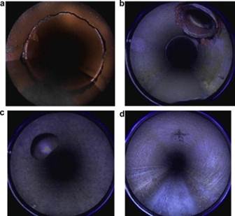
Figure
611.A – Internal Conduit
(a) Defective and open joint
– VC pipe, (b) Defective connection – VC pipe, (c) Perfect connection – VC
pipe, and (d) Exposed reinforcement – RC pipe.
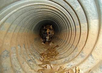
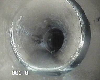
Figure
611.B – You Never Know What you Will Find
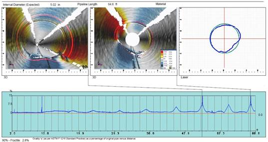
Figure
611.C – Sample Pipe Inspection Report including Ovality Observations
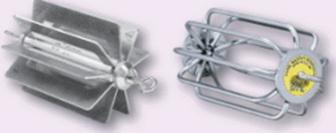
Figure
611.D – Example Mandrel Gauges
A performance survey will
document the elevations and locations of each Type A, B, and C conduit and
drainage structure to determine conformity with the Contract Documents
(Plans).
An evaluation of surface
settlements within 4 feet of the trench limits or drainage structure will be
created by an independent registered engineer and submitted to the Project
personnel.
After the performance
inspection, a survey and settlement evaluation is completed, and an independent
registered engineer will provide a review of the conduits and structures. This
independent registered engineer will provide a statement indicating that no
repairs are required, or that repairs are required, and the repair plan meets
the design requirements.
Documentation
Requirements - 611 Pipe Culverts,
Sewers, Drains and Drainage Structures
1. File the Contractor supplied Shop Drawings
with each applicable reference.
2. File the Contractor supplied Installation
Plan in the project records with each applicable reference.
3. File Contractor supplied form CA-P-1
or CA-P-3 as appropriate in the project records with each applicable
reference. Make sure all waterproofing
and field paving is noted in the comments section of the forms.
4. Enter the daily amounts installed into SiteManager as appropriate.
5. File the Contractor supplied Performance
Inspection, Performance Survey, and Surface Settlement Evaluation in the
project records with each applicable reference.
6. File the Conduit Evaluation and Drainage
Structure Evaluation as provided by an independent registered engineer in the
project records with each appropriate reference.