SS-840 Mechanically
Stabilized Earth (MSE) Walls
Be advised SS840 dated 4/19/2013
is included in its entirety at the end of this document for reference only; the
official version is available online.
Introduction
MSE walls have been constructed in the State of Ohio for
over 25 years. In previous years, there
were special provisions in the Contract that detailed the construction and
design requirements. In the old special
provisions, each wall supplier had a unique special provision. The supplemental specification (SS-840) combines all of the
special provisions into one document.
SS-840
is updated frequently. Check the plans
and addenda to see which version is included in the Contract. If a more recent version is available,
consider adopting the new version by a change order. There may be a cost or savings involved with
adopting the new version, depending on what has changed.
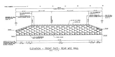
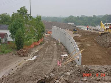
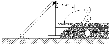
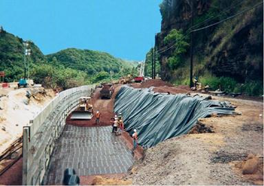
Below is a detail of a
typical MSE wall application. This is an elevation view of a MSE wall and bridge.
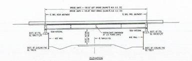
Figure
840.01.A MSE Wall Elevation View
For the same bridge, a plan
view is shown below.
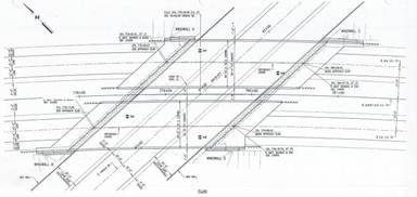
Figure
840.01.B Plan View of the MSE Wall and
Bridge
MSE wall specifications are
different than the normal construction specifications. There are both design and construction
criteria in the specifications. The
plans will detail a three line diagram of the MSE wall structure. The internal details and the construction
shop drawings are submitted after the sale of the project.
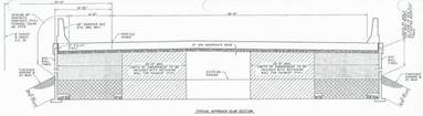
This detail shows the
reinforcing mesh in general form and the undercut.
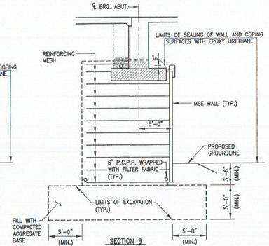
Figure
840.01.C Typical Plan Cross-Section of a
MSE Wall
In the detail below, the
Designer has laid out the select granular backfill and 203
embankment.
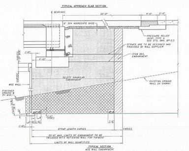
Figure
840.01.D Layout of the Select Granular
Backfill and 203 Embankment
There are applications where
the Designer may choose to place a wall on both sides of an embankment as
detailed below.
Figure
840.01.E MSE Walls on Both Sides
General
Information
The following figure details
the general configuration of the MSE wall system.
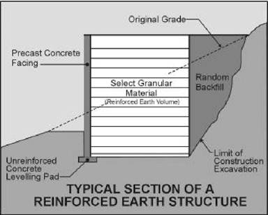
Figure
840.01.F Typical Section of an MSE Wall
Structure
Terms
The following are standard
terms that will be used throughout this text.
Coping: The coping
is used to tie in the top of the wall panels and to provide a pleasing finish
to the wall top. It is cast in place.
Filter Fabric:
A geotextile filter fabric is used to cover the joint between panels. It is placed on the backside of the panel
joints. This keeps the soil from piping
through the joints and allows excess water to flow out.
Concrete Leveling Pad: The leveling pad is unreinforced cast-in-place
concrete. The concrete is 24 inches
wide, 6 inches thick, and has a minimum compressive strength of 2,500 psi. Cure the cast-in-place concrete for a minimum
of 12 hours prior to placing the first row of facing panels.
Original Ground:
The existing ground surface at the site.
Random Backfill:
Random backfill is the backfill that is allowed in normal embankment
construction.
Select Granular Backfill: Select granular backfill is the granular backfill
that meets the gradation, corrosion, unit weight, internal friction angle, and
any other requirements.
Soil Reinforcement: Soil reinforcement holds the wall facing panels in position and
provides reinforcement for the soil. The
soil reinforcement can be strips, grids, or mesh. The reinforcement can be made
of steel (inextensible materials) or polymers (extensible materials).
Spacers:
Wall panel spacers are typically ribbed elastomeric or polymeric pads. They are inserted between panels to help
provide the proper spacing. Proper
spacing keeps the panels from having point contact and spalling the concrete.
Wall Facing Panel: Wall Facing panels or panels are used to hold the soil in position at
the face of the wall. The panels are
made of precast concrete.
Wall/Reinforcement Connection: This is where the connection is made between the
wall facing panel and the soil reinforcing.
Wood Clamps:
Wood clamps are pieces of wood with a steel bolt. It is used to hold the panel in place once
the panel is set. The panel is not
released from the crane until the wood clams are in place and tight.
Wooden Spacers:
Wooden spacers are used to space the panels at the 3/4 inch-vertical
spacing. The spacer is held between the
panels to ensure the joints are not too close or far away.
The wooden wedges should be
made from any hard wood.
Wooden Wedges:
Wooden wedges are used to help hold the panels at the correct batter during the
filling operation. The wooden wedges
should be made from hard wood, such as oak, maple, or ash.
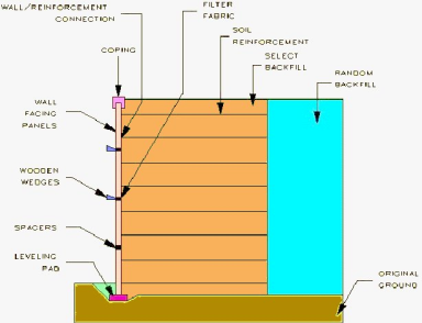
Figure
840.01.G MSE Wall Parts
Construction (840.06)
The wall system consists of
the original ground, concrete leveling pad, wall facing panels, coping, soil
reinforcement, select backfill, and any loads and surcharges. All of these items have an effect on the
performance of the MSE wall and are taken into account in the stability
analysis. A change in any of these items could have a detrimental effect on the
wall. The construction sequence follows:
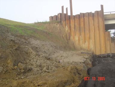
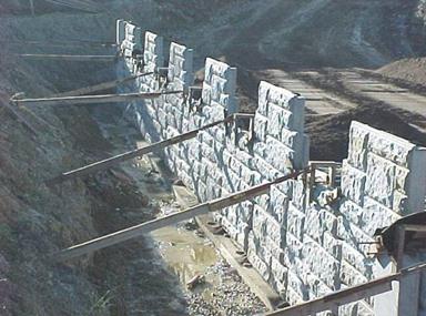
Wall Excavation (840.06.C)
There are many instances that
the MSE wall is constructed in a cut section.
This means that the excavation behind the wall needs to be supported
temporarily in order to construct the wall.
A pay item for cofferdams and excavation bracing will be included in all
MSE wall plans, but if it is missing, the specification states that the cost
for cofferdams and excavation bracing are included with the MSE wall pay
item. The Contractor is responsible for
supporting the wall excavation. All work
to support the excavation or to fill the void behind the wall will be the
responsibility of the Contractor.
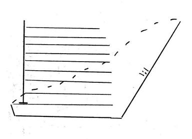
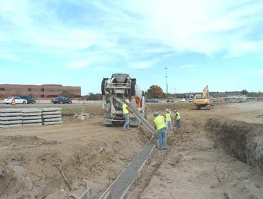
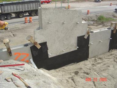
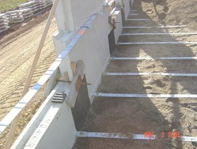
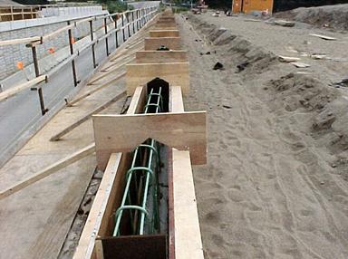
Figure
840.06.C.1 Excavation and Select
Granular Backfill Areas
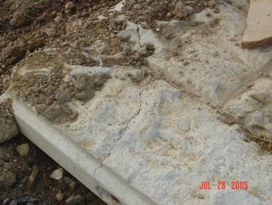
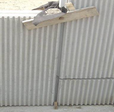
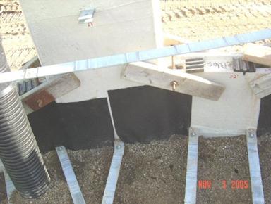
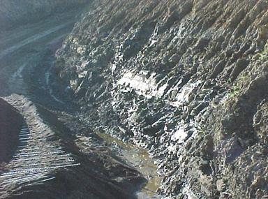
Figure 840.06.C.1 shows the
wall excavation and embankment areas.
All of the area below the dotted line is paid for under wall
excavation. All the area in the
reinforced zone is filled with select granular backfill. The area below the leveling pad is filled
with undercut material. Below is a field
view of the same situation.
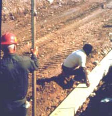
Figure
840.06.C.2 Area Behind the Wall
Foundation Preparation (840.06.D)
Preparation and Compaction
The MSE wall footprint area
needs to be prepared in the leveling pad, soil reinforcement, and select
granular backfill areas.
Figure
840.06.D.1 Foundation Preparation
Figure 840.06.D.1 above shows
a track hoe excavating down to the MSE wall foundation. All organic matter, vegetation, slide debris,
and other unstable materials, detailed as unsuitable in 703.16,
needs to be removed. Once the unsuitable
soil is removed, 1 foot outside of the foot print formed by the leveling pad
and soil reinforcement needs to be compacted.
The foundation needs to be compacted to meet the requirements of 203.07. If the foundation material is granular then
the material needs to be compacted by one of the test section methods detailed
in S-1015.
Once the foundation is
compacted, then the foundation for the wall needs to be graded level for the
full-length and width of the leveling pad and the soil reinforcement.
Foundation Evaluation
Once the foundation is
compacted, the Department needs to evaluate the foundation. Contact the District Geotechnical Engineer or
the plan design soils consultant to evaluate the foundation. This can be paid for through continuing
services during construction through the project design coordinator. The DGE or soils consultant will evaluate the
soil conditions. In the design phase, a
bearing capacity and stability analysis was performed for the MSE wall based on
the plan borings. This needs to be
reevaluated based on the existing soil conditions during construction. The DGE or soils consultant will make a field
visit to the site to determine if the foundation soils found during
construction meet the soil conditions designed for in the plans. They will then report to the Department to
give their results. The Contractor’s pay
depends on receiving this report so the Contractor will prompt the Department
to make this evaluation.
The project should review the
soils’ consultant report. The project
should ensure that the excavated soils match the soil borings performed to
design the wall. If the existing
conditions do not match plan soil borings or there are any unusual problems
with the report, contact the State Construction Geotechnical Engineer.
Undercut and Drainage
Drainage and the foundation
conditions are important parameters of the MSE wall system. Therefore, many contracts will detail an
undercut. If an undercut is in the
plans, the foundation work detailed above should be performed on the foundation
of the undercut.
The following sketch details
a standard undercut.
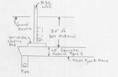
Figure
840.06.D.2 Standard Foundation Undercut
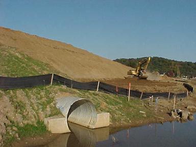
Once the foundation of the
undercut is compacted, the drainage pipe is constructed. The plans will detail the pipe with a pay
item. The pipe must be outletted. There will be at least 50 feet of outlet pipe
in the plans to outlet the pipe. The
project will have to look for an outlet if it is not detailed in the
plans. Pipe, manholes, and other items
can be used as a drainage outlet.
If the pipe cannot be
drained, move the pipe to the outside of the wall until it can be drained. The dotted pipe above the leveling pad, in
Figure 840.06.D.2, represents this pipe.
It is shown on the inside of the wall, but there is no need to put the
drain on the inside of the wall. It can
also go on the outside of the wall. The
sand on the inside is free draining.
Figure 840.06.D.3 below shows
a 5 foot undercut operation. The
replacement material in this case was a well graded blast rock. The material of choice for foundation
replacement should be Item 203,
Granular Material Type C. The upper
portion should be chocked off with at least 1 foot of Item 203, Granular
Material Type B. Geotextile Fabric Type
D should be placed below the Granular Material Type C. This will prevent the piping of fines from
the top and the bottom of the Granular Material Type C.
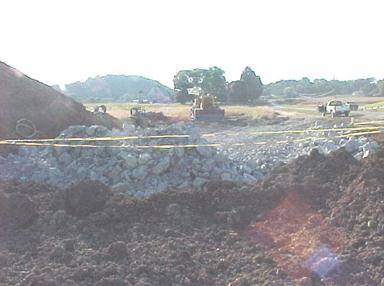
Figure
840.06.D.3 Replacing the Foundation
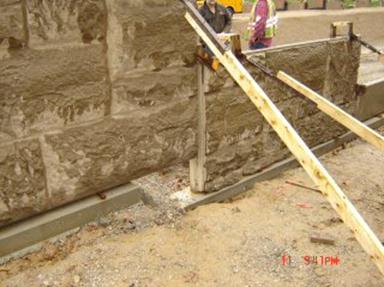
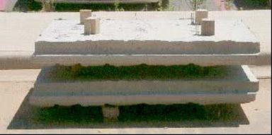
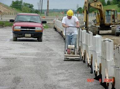
Leveling Pad Construction (840.06.E)
Once the foundation is
compacted and prepared, a 2-foot wide and 6-inch thick un-reinforced concrete
pad is constructed. The purpose of this
pad is to serve as a guide for the wall panel erection. This leveling pad is not intended to provide
significant structural foundation support in the final configuration of the
wall, but there is significant construction panel loading on the leveling
pad. Therefore, it must be properly
constructed and on a firm foundation in order to minimize potential wall
movements during the construction of the wall.
Figure
840.06.E.1 Leveling Pad Construction
The leveling pad is important
to the construction of the wall, because the leveling pad sets the horizontal
and vertical alignment of the wall. It must
be in the correct horizontal position, level, and at the correct grade.
Figure
840.06.E.2 Accurate Leveling Pad
Construction is Important
If the final wall is not
level, the panels will bind against each other causing spalling of the edges
and corners. If the wall is not started
correctly, the finished product is seldom satisfactory.
No more than 2 shims (each
3/16 inch thick) should be required to level the panels on the leveling
pad. If level cannot be obtained with
two shims, then the leveling pad and the bottom of the panels needs to be
checked.
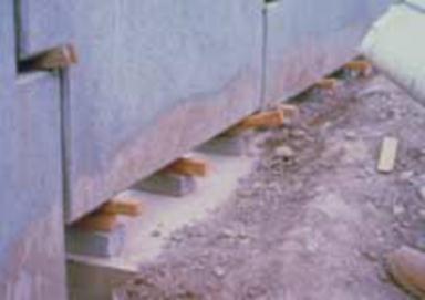
Figure
840.06.E.3 Improper Shimming
Under no circumstances are
bearing pads allowed on the leveling pad.
Bearing pads can create point loads on the panels and allow for movement
of the panels during construction.
Figure
840.06.E.4 Bearing Pads are Not Allowed
on the Leveling Pad
Care must be taken to ensure
the leaving pad is correctly aligned.
The leveling pad is 24 inches wide to allow for some alignment errors
and inconsistencies, for example, when going around corners and curves. In addition, the wider leveling pad will
supply more support during construction.
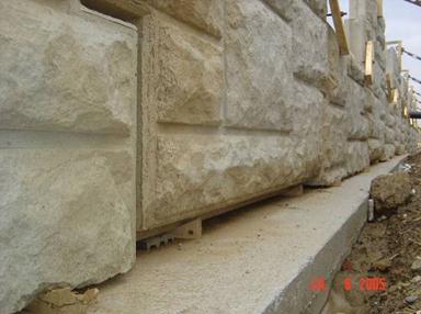
Do not allow any overhanging
of the panels off the leveling pad. If
this happens, stop the construction and investigate the problem. If needed, reconstruct the leveling pad.
Figure
840.06.E.5 Improper Overhang
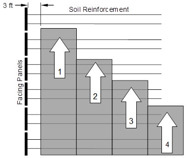
Leveling pads that change in
elevation have special challenges in design and construction. Figure 840.06.E.6 below details this
challenge. This figure is a general
step-up figure with some of the dimensions changing in the new SS-840.
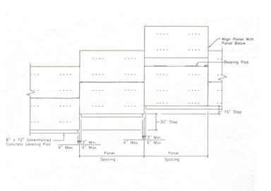
Figure
840.06.E.6 Change in Leveling Pad
Elevation
The challenge is to arrange
the leveling pad and panels so that when this elevation change occurs, the panel
is almost fully supported by the leveling pads.
Multiple elevation changes are even more difficult to construct. In all cases, a 6-inch maximum overhang along
the wall is allowed. The minimum
overhang distance along the wall is approximately 3 inches.
Figure
840.06.E.7 Acceptable if Less than 6
inch Overhang
The concrete leveling pad
must cure for at least 12 hours before wall panels can be placed.
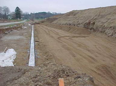
Figure
840.06.E.8 Finished Concrete Leveling
Pad
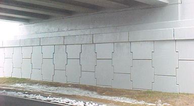
Wall Panels Types and Parts (840.04.A)
Wall panels come in many
shapes and sizes. The most common are
the square and rectangular. They can be
custom built into any configuration that will fit together. The front face can have any type of finish,
shape, texture, or other surface treatments that can be formed.
Figure
840.04.A Reinforced Earth Panels

Figure
840.04.B Rectangular Panels
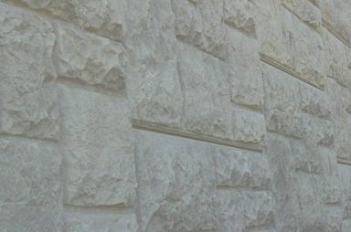
Figure
840.04.C Textured Finish Panels
Corner Panels
Corner panels provide a good
connection between the two walls and act like slip joints for the wall allowing
differential movement between the two walls.
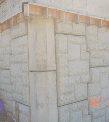
Slip Joints
Typically a slip joint is
used to handle large differential vertical movement of the wall. There are two in the figure below, one on
each side of the corner section.
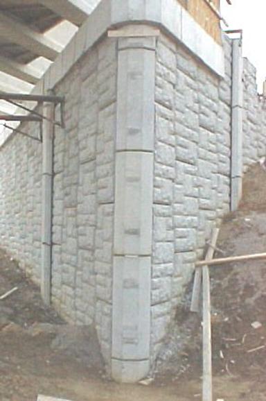
Figure
840.04.E Corner (front) and Slip Joints
(One on Each Side)
Handling, Storing and Shipping Panels (840.05.H)
Panels should be stored flat
and on spacers or dunnage. Spacers are
typically sent by supplier on pallets of panels. Spacers protect the galvanized soil
reinforcement connections from being bent or damaged by other panels. Panel faces should be kept away from areas
that are muddy to prevent staining of the face of the panel. The project should ensure that panels don’t
have spalling or cracking upon delivery to the site.
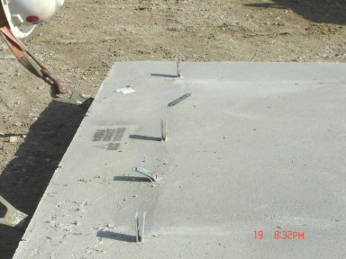
Correct storage is shown in
Figure 840.05.A. Note that the dunnage
height is more than the soil reinforcement connections to minimize damage.
Figure
840.05.A Proper Panel Storage with
Dunnage
Figure 840.05.B is an example
of improperly stored panels. The panels
in this case can get chipped or cracked.
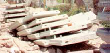
Figure
840.05.B Improper Panel Storage
The soil reinforcement
connections also can get bent.
Panel Inspection
Panel Dimensions and Tolerances (840.05.G)
When the panels first arrive
at the project, the panel documentation needs to be checked. The panels come with a TE-24. The documentation required with this TE-24 is
a record of final inspection of all precast components and the measurements of
the tolerances, strength, and dimensions of all panels. As one final check, the dimensions need to be
randomly checked at the project. The
shipment paperwork, shop drawings, and the actual panel dimensions need to be
compared to ensure that issues are found in a timely manner. The earlier in the process that these
problems are found, the easier it will be to correct the issues. Some of the panel items to pay particular
attention to are:
1. Length, width, and thickness.
2. Squareness.
3. Finish.
Physical measurements of the
panels are required. The project should
use a tape and carpenters square to check the above. All of these dimensions have an effect on the
Contractor’s ability to construct the wall within the specification tolerances.
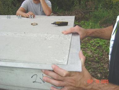
Figure
840.05.D Checking the Squareness of the
Panel
Precast Panel Rejection (840.05.J)
Damage to the Galvanized Soil
Reinforcement Connections
If the soil reinforcement
connections are damaged to the point that it inhibits the soil reinforcement from
being attached, then the panel needs to be rejected. Many times the connection is filled with
residual cement or concrete that does not allow the soil reinforcement to be
connected. If this is the case, have the
Contractor clean out the connections. Do
not cut the soil reinforcements.
If the connections are bent
more than 15 degrees from perpendicular, the panel needs to be rejected. When bent beyond 15 degrees, the galvanizing
is compromised and cannot be repaired.
Damage to the Panels
The panels also need to be
inspected for damage. Panels can be
damaged almost anywhere during the manufacturing or construction process. Many of the chips and cracks are caused by
poor handling. Chips or spalls can be
prevented by using nylon straps in the handling process. Cracks can be avoided by taking care in the
handling process. There is a list of
defects and damages in 840.05.H that are sufficient
reason for rejecting a panel. Depending
on the severity of the damage, the Contractor may propose a repair.
Figure
840.05.E Rejected Cracked Panel
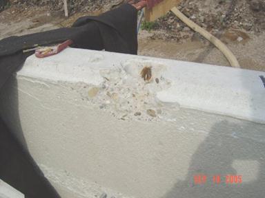
Figure
840.05.F Rejected Lifting Spall
Figure
840.05.G Repairable Lifting Strap
Spalling
Figure
840.05.H Repairable Handling Spalls
Wall Erection (840.06.G)
Panel Identification
At this point, we have
constructed the foundation, added drainage, checked the materials, and
constructed the leveling pad.
There is one last step we
need to perform before we construct the wall; the wall and shop drawings must
be checked to ensure that the correct panels are being used in the correct
location along the wall. Depending on
the wall height, the panel shape, or design, the number of soil reinforcement
connections on the back of the panel may vary.
The panels with the most connections will typically be in the lower
panels of the wall. In the upper
portions of the wall, the number of connections may be less. It is important that the panels are used in
their proper position. Below is a
typical shop drawing showing the panel organization.
Figure
840.06.G.1 Typical Panel Erection Shop
Drawing
The erection drawings have a
numerical code on each panel that depicts its position in the wall. In the above shop drawing, the letter A denotes full-height panels in the
first row and the subsequent rows until the shape changes as the panel is just
below the coping. The letter B denotes half-height panels in the
first row. The codes HX, F11, L11, KX,
K, E, EX, HJJ, KJJ, LJJ, DJJ, and EJJ denote panels just below the coping. Note
the combination of letters. R or L will be used to denote the right or
left side of the wall. A number that
follows the letters denotes the number of tie strips required for the
panels. Below is a code that details the
panel letter and numerical system.
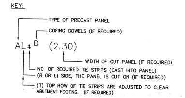
Figure
840.06.G.2 Code for Panel Placement
(Reinforced Earth)
The code that is detailed
above is for Reinforced Earth walls. The
code for other wall systems will be different, and the code for a particular
wall system may change at any time. The
codes are marked on the back of the panels for easy reference during
construction. Below is a photo of the
marking on the back of a panel.
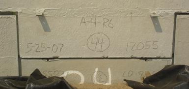
Figure
840.06.G.3 Actual Panel Markings
The above markings show piece
A has 3 tie strips and is on the right side of the wall. Other required markings include date of
manufacturing, production lot number, and the precaster’s and accredited
manufacturer’s inspection and acceptance marks.
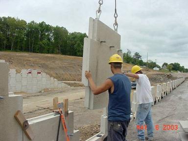
Placing the Panels
Picking up the panels is an
important aspect of the construction procedure.
If the panels are not properly picked up, spalling or cracking can
occur. The figure below shows the
correct method of picking up the panels.
The crane lifts the panel so that no concrete to concrete contact
occurs.
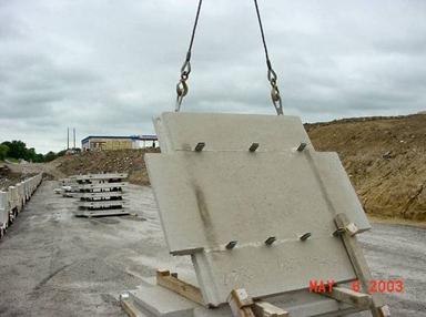
Figure
840.06.G.4 Picking up the Panels
The correct placement of the
first row or two of panels is very important.
When the panel construction is not started correctly, the finished product
is rarely satisfactory.
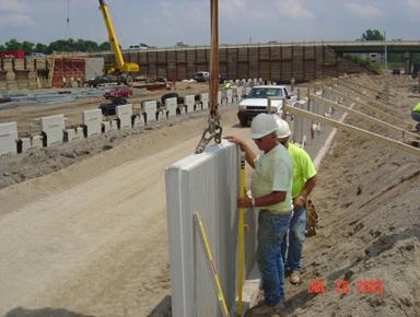
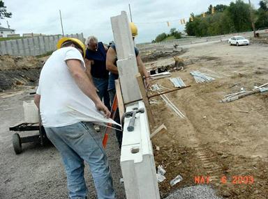
In the figure below, a chalk
line is placed on the leveling pad to properly align the panels along the
leveling pad. Sometimes a 2×4 is used to
align the panels. Adjust the alignment
using a crowbar as shown below. At this
point, the panel is still supported by the crane.
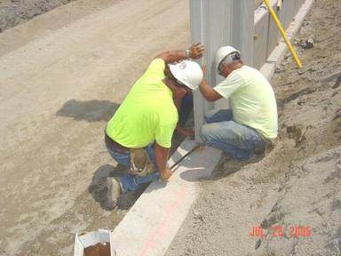
Figure
840.06.G.5 Proper Placement
As one last check of the
horizontal alignment, the panel to panel horizontal offset needs to be checked.
Use a straightedge across the panel horizontal joints to ensure that the panel
to panel horizontal offset does not exceed 1/2 inch.
The first row may be composed
of both half- and full-height panels. A
photo of full- and half-height panels is shown below. The panels need to be in proper alignment and
level.
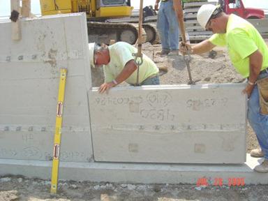
Figure
840.06.G.6 Half Height Panels
Horizontal Leveling
Once the panel is placed on
the leveling pad, the panel needs to be leveled horizontally. A 6-foot level rod is placed on the top
surface of the panel to determine if it is level.
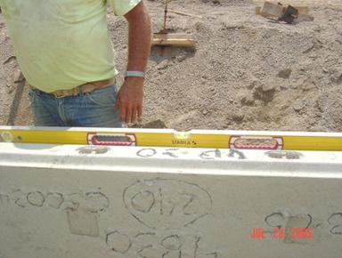
Figure
840.06.G.7 Proper Horizontal Leveling
If it is not, shims are
placed under the panel in order to make the panel level. Galvanized metal washers or rubber shims are
allowed. A maximum 3/8 inch in total
shim height, at any location, is allowed.
If more shims are required, then the leveling pad is not level or the
panel bottoms are not flat. In either
case, the issue is the Contractor’s responsibility to resolve.
Figure
840.06.G.8 Metal Shims to Level the
Panels
Horizontal Joint Spacing
Without the correct joint
spacing, panel corners will crack and spall with the wall settlement. Spacing blocks must be used. As the panels are placed together, the
3/4-inch spacers are placed in the joints.
The panels are maneuvered so that there is contact between both panels
and the joint spacer. The required joint
spacing is 3/4 inch ± 1/4 inch. If this
spacing cannot be achieved, the Contractor is required to submit an action plan
to correct the problem. The spacer is
shown in the figure below. If the panel
is moved during the joint spacing adjustment, then the horizontal leveling
should be checked again.
Leave the horizontal spacers
in until half of the panel height is filled with backfill.
Figure
840.06.G.9 Wooden Joint Spacers
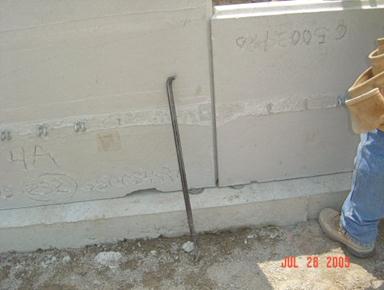
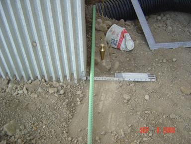
Vertical Alignment
The panels need to be set
with a backward batter toward the inside of the wall. The typical batter is about 1/8 inch per foot
of panel height or about 1/2 to 1 inch per panel. Compacting the backfill behind the wall
pushes the panel outward, so the panel will be vertical once the fill is placed
against it. The amount of batter is
adjusted for the site conditions, such as backfill properties; the finer sand
may require a more batter. If a fine
graded material, such as foundry sand is used, then it may require a 1-inch
batter. A well-graded, crushed limestone
may require a 1/2-inch batter.
Figure
840.06.G.10 Batter Check
A level with a batter spacer
is placed on the outside or inside of the wall.
Use the outside of the wall unless textured. The batter spacer can be used on the top or
bottom of the level. If the level is
used on the outside of the wall, the batter spacer is used on the top of the
level. If the level is used on the
inside of the wall, the spacer is used on the bottom of the level. The spacer is usually duct taped on to the
level at a thickness of the batter. In
the figure below, it shows the batter spacer being used on the inside of the
wall.
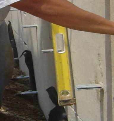
Figure
840.06.G.11 Vertical Leveling Spacer on
the Inside of the Wall
The level can also be used on
the outside of the wall as shown below.
Figure
840.06.G.12 Vertical Batter on the
Outside of the Wall
Vertical and horizontal
alignments and joint spacing needs to be checked one last time prior to
temporarily locking the panel in place.
For the entire time the horizontal leveling, joint spacing and vertical
alignment is being adjusted, the panel is still suspended from the crane so
that the panel is not damaged.
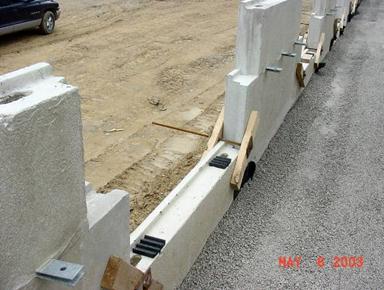
Triangular Wedges and Wood Blocks
Wooden triangular wedges are
used to lock the panel into vertical alignment once the wall is battered with
the level. The wedges are shown below on
the leveling pad.
Figure
840.06.G.13 Wooden Wedges for Vertical
Alignment
No more than three levels or
rows of the wooden wedges should be placed in the wall without removing the
lower row. If more than three levels of
wedges are used they may become bound in the wall making them very difficult to
remove and can cause the panel to spall.
Wooden clamps are used to
hold the panels together. Wooden clamps
are two pieces of wood held together with a long bolt. The bolt is tightened to hold the panels
together.
Figure
840.06.G.14 Wooden Clamps
Triangular wedges are also
used in combination with the clamps to secure the panels as shown in the figure
below.
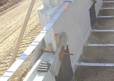
Figure
840.06.G.15 Triangular Wedges and Wooden
Clamps
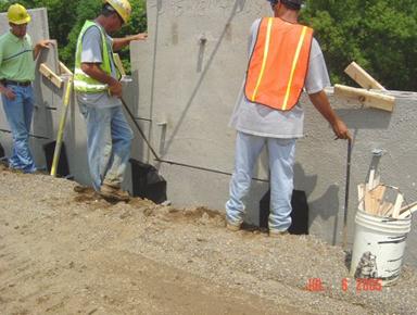
External bracing is required
for the first row of panels to maintain stability and alignment. Typical bracing is shown below.
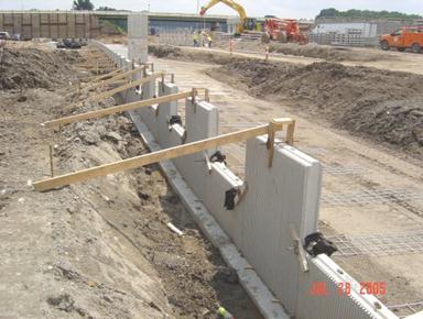
Figure
840.06.G.16 Proper Bracing
At this point, the geotextile
fabric and the select granular backfill are placed to the height of the wooden
clamps. These steps will be described in
detail later.
When panels are placed on one
another, a horizontal bearing pad is used to separate the panels. A minimum of two bearing pads are used. The horizontal joint should be 3/4 inch at
this point. Some Accredited Wall Systems
may supply thicker bearing pads. This is
anticipation of the bearing pads deflecting under the load of the wall. Check the accepted wall shop drawings to
ensure that the thicker pads are allowed.
Figure
840.06.G.17 Bearing Pads on the Second
Row
Subsequent panel rows are
placed between panels that were previously placed. The ability to properly
space and align these rows relies on the proper placement of the lower
rows. All of the error produced by the
lower rows is propagated upward and is difficult to correct. The same leveling, joint spacing, vertical,
and horizontal alignment applies to all the rows.
Figure
840.06.G.18 Panel Placement
Panel-to-panel vertical
offset needs to be checked as soon as the next row of panels is placed. Use a straightedge across the vertical joints
to ensure that the offset between panels is less than 1/2 inch.
Figure
840.06.G.19 Second Row of Panels Placed
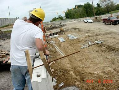
The process starts all over
again as crow bars are used to align the next row of panels.
Figure
840.06.G.20 An Existing Joint Offset
Problem
Alignments need to be checked
periodically to ensure proper alignment.
This will ensure that problems are spotted early and corrections can be
made before the panels get too far out of alignment.
Figure
840.06.G.21 Wall Alignment
As stated before, the panels
are battered back so that the fill placement can move them forward into a
vertical position. After the fill is
placed, check the vertical position of the wall. After the third row of panels
is placed, use a plumb bob to check the vertical alignment. Hold the plumb bob at the top of the panel
and measure the out of plumbness, as shown below.
Figure
840.06.G.22 Checking Vertical Alignment
with a Plumb Bob
The tolerance is 1/2 inch in
10 feet. By using a 10-foot straightedge
and a level or a plumb bob, this tolerance can be measured. At no point along the straightedge can any
portion of the panel be more than 1 inch away from the string or straightedge.
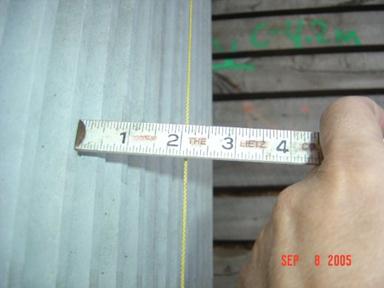
Figure
840.06.G.23 Measure from the Wall to the
String (Out of Plumb Here)
A summary of the wall
erection tolerances are listed below:
1. Vertical Tolerance: 1/2 inch overall and 1 inch at any
point.
Use a 10-foot straightedge,
2. Horizontal Tolerance: 1/2 inch overall and 1/2 inch at
any point.
Use a 10-foot straightedge.
3. Panel to Panel Tolerance: 1/2 inch horizontal and
vertical.
Use a 6-foot straightedge.
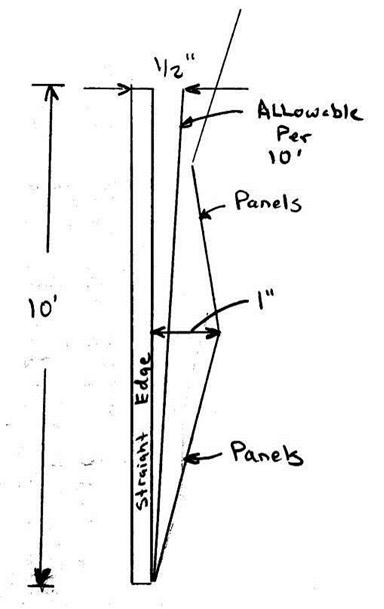
Figure
840.06.G.24 Panel Tolerances
Filter Fabric Placement and
Inspection
Filter fabric is placed
across the joints so that the granular backfill does not leak through the
joints to the outside of the wall. The
minimum lap on each side of the joint is 1 foot on each side of the joint and 1
foot along any cut piece of fabric along the joint. These requirements apply to horizontal and
vertical joints.
The fabric is cut in lengths
to cover the horizontal and vertical joints.
Once the fabric is cut, the fabric is laid on a flat surface. An adhesive is used to hold the filter fabric
in place until the select granular backfill is placed over the joints. A thick bead of the adhesive, approximately
1/2 inch in diameter, is applied around the entire perimeter of the fabric,
about 2 inches from the edges of the fabric.
See the figure below.
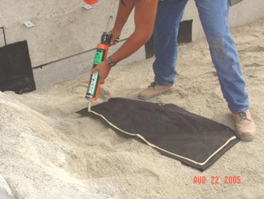
Figure
840.06.G.25 Correct Application of the
Adhesive
Figure
840.06.G.26 Fabric Completely Covering
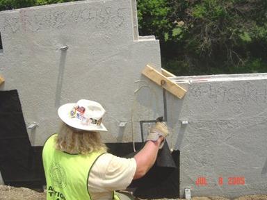
the Joints
Once adhesive is applied to
the fabric, it is immediately placed on the wall. Ensure that the fabric is placed on the wall
before the adhesive dries. The fabric needs to fully engage the wall at all
locations to ensure that the sand does not leak through the joints.
Figure
840.06.G.27 Wrong Application of the
Adhesive on the Wall
As shown above, randomly
placing adhesive on the wall does not ensure that the joint is properly
sealed. More adhesive is not necessarily
good. Correctly applied adhesive and the
appropriate placement of the fabric is the solution.
In the past, some projects
have only glued the top portion of the fabric applied to a horizontal
joint. This method should be
discontinued and not be allowed.
Figure
840.06.G.28 Partial Gluing (Do not Allow
this)
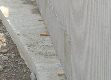
Small tears or wrinkles in
the fabric can cause leaking of the sand.
Any leaking of the sand through the joints is not tolerable. Leaking sand is like a leaky water pipe; it
never gets better with time, it only gets worse.
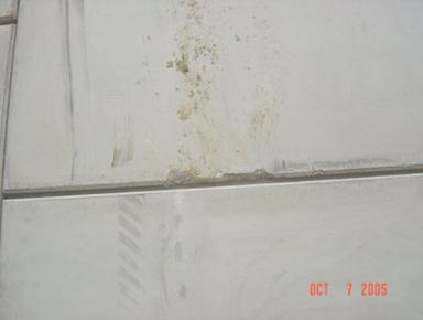
Once the fabric and the
backfill are placed, the project should go around to the front of the wall to
inspect the joint spacing and the fabric’s ability to hold the sand behind the
wall. Take a flashlight and inspect the
joints. Look to see if the fabric is in
place and holding the sand back.
Look for deposits of sand in
the horizontal and vertical joints, as shown below.
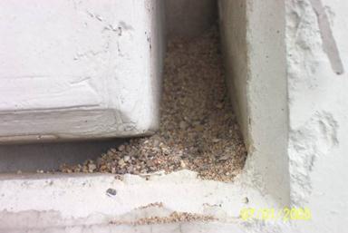
Figure
840.06.G.29 Sand in the Joints on the Outside of the Panels
Sand deposits may be caused
by sand falling over the wall during construction or the sand is leaking
through the joints. By carefully
inspecting the joints, the source of the sand deposit will be found. In the figure below, the sand is leaking out
of the joints and being deposited on the ground.
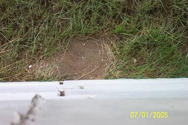
Figure
840.06.G.30 Sand Falling from Several
Joints
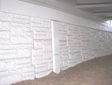
After further inspection of the
wall from behind, it was found that the fabric was not placed in the upper
portion of the MSE wall. This project
was about three-years-old at the time of the inspection. A thorough inspection during the construction
of the wall would have prevented this maintenance problem.
Figure
840.06.G.31 No Fabric Placed Behind the
Wall
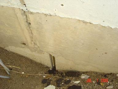
Below is a photo of a wall,
which was taken shortly after construction.
As you can see, there are sand deposits at the bottom of the slip
joints. In this case, the fabric was
either not placed or improperly placed.
Figure
840.06.G.32 Sand Piles around Slip
Joints
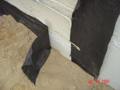
In the figure below, looking
behind the wall at a typical slip joint during construction, you can see that
the fabric has to go around a bend.
Careful construction in this location is required. When placing fabric around corners or
obstructions, leave the fabric loose so that it does not tear during the
placement of the backfill in the corner.
Figure
840.06.G.33 Fabric Placement around a
Slip Joint
There are a lot of other
items of work that obstruct the proper placement of the fabric in this
situation. In the figure below, there
are the reinforcing steel, wooden clamps, and a settlement plate that the
fabric needs to go around. There is
ample opportunity for sand to leak around the fabric if we are not careful.
Figure
840.06.G.34 Obstructions near a Slip
Joint
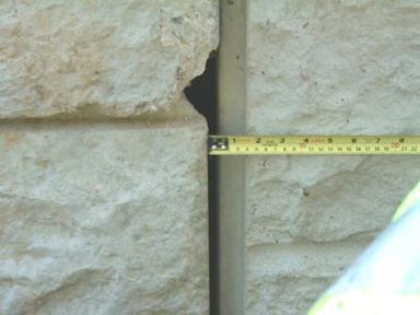
The joint spacing needs to be
reexamined in the front of the wall. We have
previously checked and recorded the joint spacing when the panels were
constructed. There may be cases where
after the wall is constructed, the joint spacing is wider than the allowable
3/4 inch plus 1/4 of an inch.
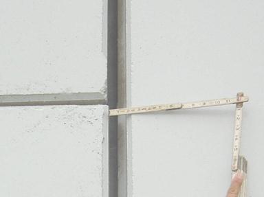
Figure
840.06.G.35 Wide Joint and Exposed Fabric
The joint gap in the above
figure is almost 1-3/4 inch. The gap is
wider than the panel’s ship lap, therefore, exposing the fabric. The width of the ship lap is about 1-1/2
inches. In the above case, the
Contractor needs to be instructed to place expansive foam and caulk to the
joint to prevent the fabric being exposed to sunlight.
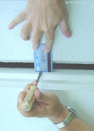
Sunlight can cause the fabric
to deteriorate with time, whether direct or indirect. A flashlight is used to minimize sunlight
exposure to the fabric. A flashlight is
held perpendicular to the joints, about 6 inches away from the joint. The described flashlight test is shown in the
figure below.
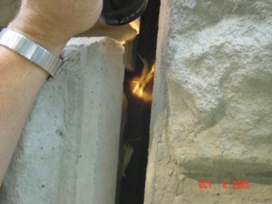
Figure
840.06.G.36 Flashlight Test
If the light from the
flashlight can be seen on the fabric, then the joint needs to be sealed. Expanding foam and caulk is used to cover the
fabric.
There have been instances where,
after the wall has been constructed, the fabric is destroyed during water
jetting operations. Water jetting is
used to clean the panels prior to sealing; therefore, examine the joints after
the sealing operation.
As a final note on the wall
construction, continue to monitor the wall throughout the duration of the
project. The wall is designed and constructed to tolerate movement. Too much movement is detrimental to the wall
and the structural items around the wall.
Select Granular Backfill Placement (840.06.I)
Material
The granular backfill
materials have special requirements that are not normally associated with
granular material in other items of work.
There are material requirements such as pH, resistivity, chloride, and
sulfate levels. These requirements
minimize the corrosion of the metal soil reinforcement. The project and district test lab need to
review and evaluate the test data for these requirements. Ensure that the test results meet the
specification requirements and that the correct tests were taken on the
materials. If the backfill material does
not meet these requirements, then there is a high probability that the metal
soil reinforcement will prematurely corrode and the life of the MSE wall will
be shortened.
Another requirement is the
internal angle of friction. The internal angle of friction is critical to the
design of the wall. The wall design and
the factor of safety are sensitive to numerical value of the friction angle. The factor of safety can change dramatically
with only a few degrees of friction angle change. The design friction angle is 34 degrees. The test ensures that the design assumption
is valid.
The specification allows the
use of granular material Type 2 which is old Item 310 material. It can be very fine sand or a coarse 304
type material. Since economics
drives the material choice, the vast majority of the time sand is used.
The specification also allows
the use of Item 304
material. This material is a well
graded and very stable material.
It is a requirement to use
the Item 304
material for the first 3 feet of backfill behind the wall. This is a stronger material and is more
resistant to the influences of water.
After the first 3 feet are placed, the sand or the 304
may be used.
Select Granular Backfill
Placement and Compaction
The below placement and
compaction procedures were developed to produce uniform compaction of the
select granular backfill (SGB). Uniform placement and compaction of this
material is essential in order to keep uniform pressure against the wall as it is
constructed. Unnecessary compaction or
non-uniform compaction of this material can create bulges in the wall or loose
areas in the backfill behind the wall.
This procedure is to be followed all the way to the top of the wall.
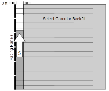
On the initial row of panels
(and only the initial row of panels) the backfill is not placed against the
panel until the first layer of soil reinforcement has been connected and the
initial layer of backfill is placed and compacted on top of the soil
reinforcement. This is to keep the
bottom of the panels from “kicking out.”
If the SGB cannot be compacted effectively below the first row of soil
reinforcement, because some manufacturers may have mesh that we cannot compact
through, then the wall supplier will need to design a kicker to prevent the
wall from kicking out at the bottom.
Figure
840.06.I.1 Backfilling for the First
Panel Only
Once the backfill is placed
and compacted to the elevation of the first layer of soil reinforcement as
shown in Figure 840.06.I.1, the soil reinforcement is connected. Then the next loose lift is placed on top of
the soil reinforcement 3 feet away from the wall. The material is then leveled by moving it
parallel to the wall and windrowing the material toward the soil reinforcement
ends and away from the wall. See Figure
840.06.I.2 for the spreading operation details.
This SGB material which is 3 feet away from the wall is then compacted
in the same way as it was placed.
Figure
840.06.I.2 Procedure for SGB Placement and Compaction
Once this is completed, the
void is filled and compacted next to the wall to the elevation of the soil
reinforcement. The material void left
above the soil reinforcement is then placed and compacted. Place and compact this inner most 3 feet as
detailed in Figure 840.06.I.3. Within 3
feet of the wall, the SGB is compacted with six passes of a mechanical tamper
or vibratory plate compactor. The
compaction equipment should have a centrifugal force between 1/2 to 2 tons.
Figure
840.06.I.3 Place and Compact the SGB
Next to the Facing Panels
Use the procedure detailed in
Figures 840.06.I.2 and 840.06.I.3 for the SGB placement and compaction
procedure for the remaining sections of wall.
The SGB is placed in maximum
8-inch loose lifts. It may be helpful to
mark the lift thicknesses on the back side of the wall panels. The action of moving the SGB parallel to the
wall and windrowing or compacting the material toward the reinforcement ends
and away from the wall takes out the slack in the reinforcement and locks the
reinforcement and the panels in position.
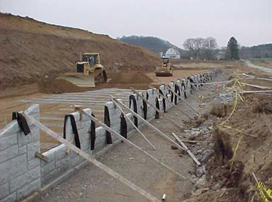
Figure 840.06.I.4 Improper Spreading Technique
(From back to front is improper)
Any slack in the
reinforcement should be removed to avoid excessive panel movement. With geogrid soil reinforcement, some tension
needs to be applied to the reinforcement by means of a kicker tension device or
a rod during this backfill placement.
Figure
840.06.I.5 Final Compaction Operation Next to the Wall
Consistent placement and
compaction of SGB are one of the keys to a good performing MSE wall.
Inspection and Compaction Testing
(840.06.N)
No compaction testing is
performed on the SGB within 3 feet of the wall. For the SGB, more than 3 feet
from the wall facing panels, smooth-drum vibratory rollers weighting between 6
and 10 tons are required to compact the material. The compaction testing is performed according
to Supplement 1015
and SS 878.
SS 878
details the general inspection and compaction testing requirements when
these services are hired through the Contractor. All of the inspection and compaction
procedures that are required for ODOT inspection personnel are required for the
Contractor’s personnel under SS 878. A trained compaction and inspection person is
required under this specification. All
of the Department inspection and compaction forms are to be used.
Supplement 1015
details the inspection and compaction procedures to be employed during the
work.
At the beginning of the work,
a test section is constructed to determine the density requirements for the
select granular backfill. The moisture requirements are determined by using the
moisture density curve for the Method A test section. For the Method B test section, the moisture
requirements are determined by constructing several test sections at different
moisture contents. For determining which
test section is used, see Supplement 1015.
The select granular material
is compacted between 3 percent below and optimum moisture content. If additional water is required after
spreading the material, then water must be added to meet these
requirements. The moisture content of
the select granular backfill material prior to and during compaction is to be
uniformly distributed throughout each layer of material. If watering is required after spreading, the
project should dig up the material to ensure that this requirement is met.
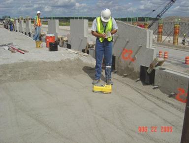
Figure
840.06.N.1 Taking a Compaction Tests
Once the moisture content is
correct, the test section is constructed to determine the density requirements
for the remaining areas of the select granular backfill. This test section is
approximately 40 square yards. This test
section is compacted until a maximum density is achieved. The number of passes and the maximum density
is used in the remainder of the work. A minimum of 98 percent of the maximum
density is required. A new test section
should be constructed if the compaction tests are not close to the maximum
value. Use the same number of passes if the material or foundation conditions
change.
In the figure below, the
compaction starts 3 feet away from the wall and proceeds to the back of the
soil reinforcement. In the background,
the area within 3 feet from the wall is compacted after the roller compaction
is complete. This procedure is detailed
in the previous section.
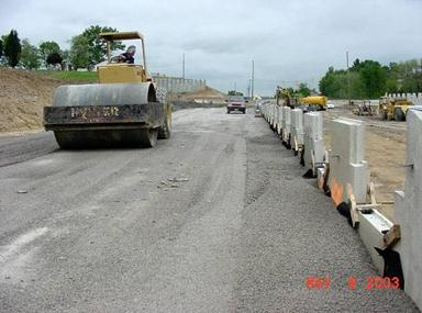
Figure
840.06.N.2 Smooth-drum Vibratory Compaction Equipment
Wall Drainage (840.06.F)
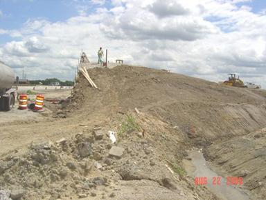
At the end of each day’s
operation, the Contractor is to shape the last layer of backfill to allow
rainwater to runoff away from the wall face.
The drainage system is under or in front of the wall. This will permit
the water to dissipate from the system.
The SGB of the wall can be drained laterally to dissipate out to the
sides. Drainage problems can develop
similar to the figure below.
Figure
840.06.F.1 Washout around the Soil
Reinforcement
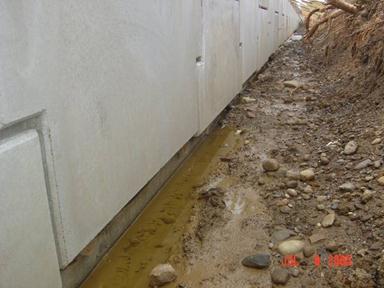
Water ponding in front of the
wall has been a problem is the past. In the
figure below, you can see the ponding of the water in front of the wall. This is not acceptable.
Figure
840.06.F.2 Water Ponding in Front of the
Wall
It is required to pump the
water out of this area immediately after the water is ponded. In addition, once the wall is erected up to
the ground elevation, this void is filled with embankment material. This will further stabilize the wall.
If water is ponding behind
the wall during construction as shown below:
Figure
840.06.F.3 Water Ponding Behind the Wall
Then collect the water by
using a drainage curtain as detailed below:
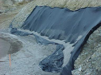
Figure
840.06.F.4 Drainage Blanket
Side slope erosion has been a
problem in the past. One solution has
been to construct 2 feet of embankment on the side slopes. This will bury the highly
erosive select granular material and erosion can be minimized.
Figure
840.06.F.5 Protection of the Erosive Side Slopes with Embankment
Soil Reinforcement Installation (840.06.H)
Soil Reinforcement Storage
The soil reinforcement is
used to tie the wall to the soil. Like
the panels, the soil reinforcement should be stored on dunnage and carefully
handled to prevent damage. Damage may
include bending of the metallic reinforcement and damaging the
galvanization. The geogrid soil
reinforcement should not be torn, cut, left in the sun, or otherwise damaged.
No equipment should be
allowed to run directly on the reinforcement.
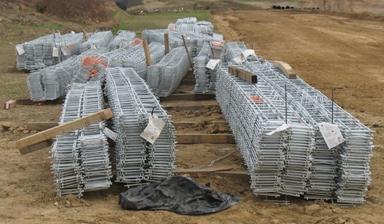
Figure 840.06.H.1
Reinforcement Storage on Dunnage
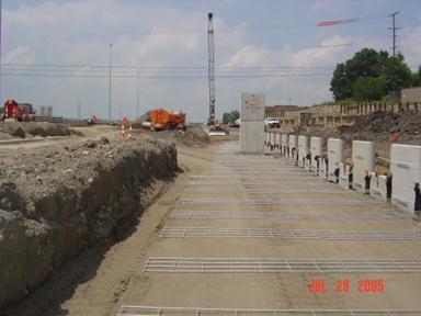
The project should check for
required length and gauge of steel reinforcement. Check the condition of steel reinforcement
upon delivery to the site. Below is a
typical plan view of the soil reinforcement on a project. The length of the reinforcement from the wall
is directly proportionate to the height of the wall. The wall height below is the highest in the
center and the length of the reinforcing is the longest. The length of the reinforcing cannot change
from the bottom to the top of the wall.
It can only change along the wall due to changes in the height or design
changes.
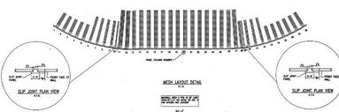
Figure
840.06.H.2 Typical Reinforcement Layout
Below is a detail of a
cross-sectional view of the soil reinforcement in the same wall. Notice the soil reinforcement connection to
the wall and regular intervals. The
length of the reinforcement is the same from the bottom of the wall to the top
of the wall. Many of these walls are
placed below an abutment as detailed below.
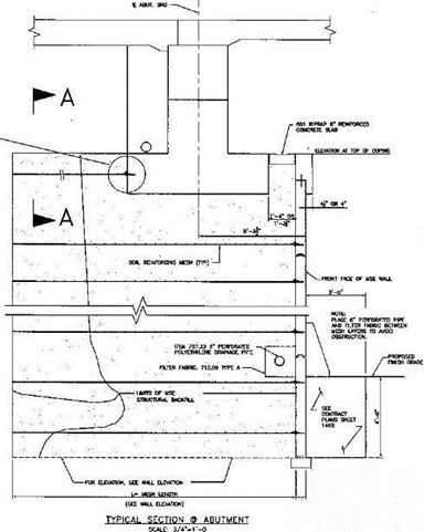
Figure
840.06.H.3 Cross-Section of the Soil
Reinforcement Layout
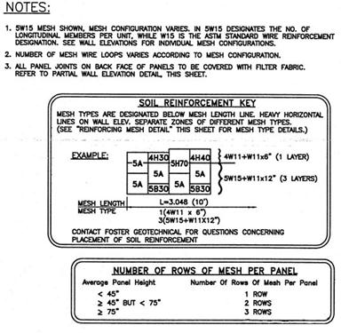
Below are the reinforcing
mesh codes for a Foster wall. These
codes were used on past projects. For
Foster walls, the reinforcing mesh will change frequently. The project should familiarize themselves
with the codes on the shop drawings and ensure that the correct mesh types are
placed in the proper location.
The figure below details the
wire mesh codes. Careful review of these
keys is required by the project.
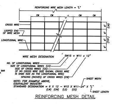
Figure
840.06.H.4 Reinforcing Mesh Details
Below is a sample of how the
reinforcing mesh is laid out as it relates to the panels. The panels are numbered in the example and
the type of reinforcing mesh is detailed beside the panel type.
Figure
840.06.H.5 Reinforcing Panel and
Reinforcing Key
Typically, the reinforcement
is placed perpendicular to the wall face. Any slack in the reinforcement should
be removed. The geogrid soil
reinforcement should have some tension placed in the reinforcement. By using the placement and compaction procedure
detailed in the previous section, it will keep the tension in the soil reinforcement.
Once the fill is compacted to
the elevation of the soil reinforcement, the soil reinforcement can be attached
to the facing panels and placed perpendicular to the face of the wall on top of
the compacted material.
Connections
Connecting the soil
reinforcing to the wall is relatively simple operation. There are three connections that will be
detailed below.
Reinforced Earth Connection
A Reinforced Earth wall’s
connections and soil reinforcement consist of galvanized strips, tabs
manufactured in the wall, and nuts and bolts to connect them. There are tabs with holes that stick out of
the wall about 3 inches. The tabs have a
top and bottom and go around the strips when they are connected.
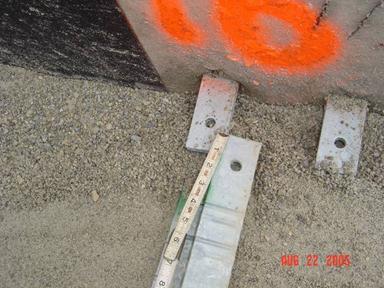
Figure
840.06.H.6 Reinforced Earth Connections
and Strips
At times, there is concrete
inside the tabs that make it difficult to place the strips inside the
tabs. The concrete needs to be cleaned
out to line up the holes. Many times the
Contractor will cut the strips instead of cleaning out the concrete. Do not allow the strips to be cut in the
field. This can reduce the strength of
the connection. Also, the galvanizing of the strip will be compromised and the
strip will prematurely rust.
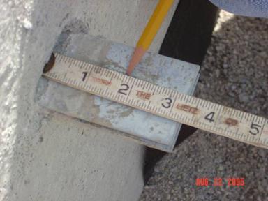
Figure
840.06.H.7 Tabs for Reinforced Earth Connections
Once the holes are lined up,
the bolt is inserted from the bottom up and the nut is tightened. By placing the bolt from the bottom, it is
easy to see if the nut has been placed on the connection.
Figure
840.06.H.8 Bolted Reinforced Earth Connection
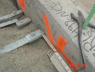
Below are multiple strips
connected to the wall for a Reinforced Earth wall. Leaving the select granular backfill lower at
the tabs is acceptable. The select
granular backfill needs to be as close to the strips as possible for all wall
types.
Figure
840.06.H.9 Reinforced Earth Multiple Connections to the Wall
Wire Mesh Connection
The connection for steel wire
mesh soil reinforcement consists of hooked eyelets in the panels and
reinforcing mesh with two transverse bars at the end. The end of the wire mesh is laid with the two
transverse bars resting on top of the hooked eyelets. A rod is inserted through the eyelets,
locking the mesh into place, as shown below.
Wooden wedges are then hammered between the wall and the mesh to put the
eyelets in full contact with the mesh and the soil reinforcement in tension.
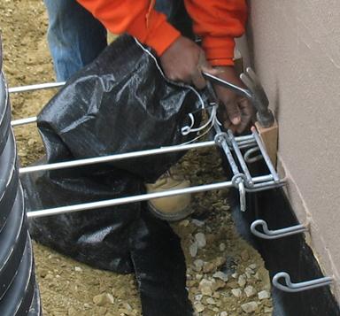
Figure
840.06.H.10 Wire Mesh Type Connection
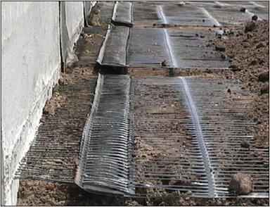
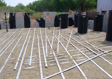
Below is a typical layout of
the soil reinforcement of a wire mesh wall.
Figure
840.06.H.11 Mesh Steel Laid Out
Geogrid Soil Reinforcement
Connection
The connection for geogrid soil
reinforcement consists of short sections of geogrid cast into the panels and a
plastic bodkin bar. The ribs of the
geogrid soil reinforcement are meshed with the short sections of geogrid that
are cast into the panels. The plastic bodkin is then weaved between the two
sets of ribs and the soil reinforcement is pulled tight. The completed connection is shown below.
Figure
840.06.H.12 Geogrid Soil Reinforcement Connection
Figure
840.06.H.13 Overview of Geogrid Soil Reinforcement
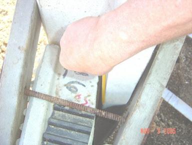
Obstructions
There are times when the soil
reinforcements have to go around obstructions.
It is not acceptable to simply leave out the reinforcement at that
location. This would create a weak
location along the wall.
At horizontal obstructions,
such as pipes, the reinforcement should not be angled more than 15 degrees up
or down. All situations that exceed 15
degrees must be detailed on the accepted shop drawings or acceptable to the Office
of Geotechnical Engineering. The
soil reinforcement must have a 4 inch clearance above or below the
obstruction. When clearing horizontal
obstructions, the reinforcement should be smoothly curved around the
obstruction. The reinforcement should
not be kinked at any time.
The detail below shows a
horizontal obstruction lower than the soil reinforcing and connection.
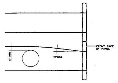
Figure
840.06.H.14 Soil Reinforcement going
over a Horizontal Obstruction
The detail below shows a horizontal
obstruction higher than the soil reinforcing and connection.
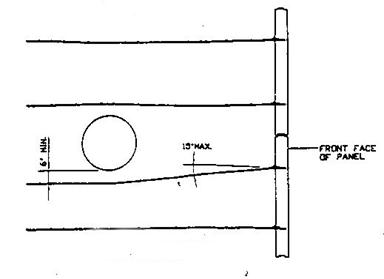
Figure
840.06.H.15 Soil Reinforcement going under a Horizontal Obstruction
The photo below shows the
soil reinforcement going under a storm sewer line.
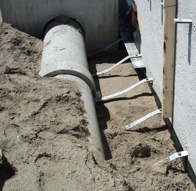
Figure
840.06.H.16 Soil Reinforcement going
under a Storm Sewer Line
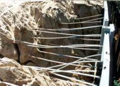
At vertical obstructions,
such as piles or catch basins, if the reinforcement must be splayed more than
15 degrees for steel strips or 5 degrees for geosynthetic strips from
perpendicular to the facing panels, the accepted shop drawings should detail a
modification. All situations that exceed
the 15 or 5 degree limits must be detailed on the accepted shop drawings or
acceptable to the Office
of Geotechnical Engineering. It may
require additional reinforcement length to meet design.
Figure
840.06.H.17 Soil Reinforcement Splayed
Around Piles
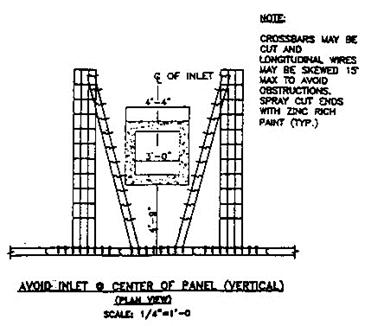
In the detail below, the soil
reinforcement was designed around the inlet by using a galvanized angle in
front of the inlet and keeping the reinforcing steel perpendicular to the
wall. Again, this would have to be
detailed on the acceptable shop drawings.
Figure
840.06.H.18 Typical Details for Obstructions
Below
is a photo of the galvanized angle in front of the catch basin to allow the
soil reinforcement to be placed around the catch basin.
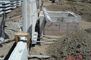
Figure
840.06.H.19 Field Example of the Reinforcing Around an Obstruction
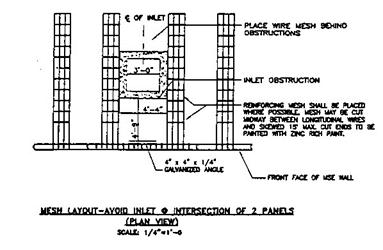
In the detail below, the
reinforcing mesh is cut and splayed around the inlet. No angle is required in front of the inlet.
Figure
840.06.H.20 Cutting the Mesh to go
around the Obstruction
Coping (840.06.K)
The coping is placed on the
top of the wall. It is used to smooth out
the appearance of the top of the wall and to connect adjacent panels at the top
of the wall. The wall is completed when
the coping is properly installed on top of the wall. The coping has to be cast in place on the top
of the wall.
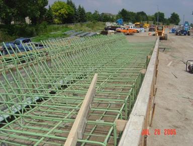
Here is the typical form and
reinforcing steel for the coping.
Figure
840.06.K.1 Forming the Coping
Moment Slab
The moment slab is put on the
top of the wall to prevent vehicles from going off the roadway. It must have a large support system to resist
these loads. The reinforcing steel is
shown below.
Figure
840.06.K.2 Moment Slab Reinforcing Steel
The finished moment slab is shown
below.
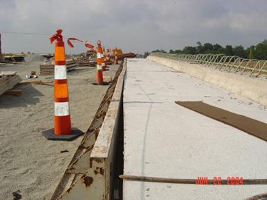
Figure
840.06.K.3 Completed Moment Slab
If your project has a
concrete pavement on top of the wall, there may be a problem with crack
propagation of the barrier joints on to the pavement. Review these details carefully and make
adjustments as required.
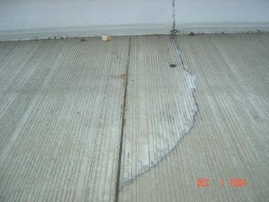
Figure
840.06.K.4 Align the Joints of the
Barrier and the Concrete Pavement
Design Conflicts, Design and
Construction Loads
Before the actual start of
construction of the wall, the various parts of the plans (shop drawings,
drainage, lighting, etc.) need to be compared to the contract wall plans to
check for conflicts. A conflict may not
have been noticed in the design stage.
If the plans show heavy loads on the wall and the shop drawings do not
indicate it, the Office
of Geotechnical Engineering should be contacted. The Designer may have missed loadings from
various types of structures. If they did
not take these loads into consideration, the wall could bow or even fail. This also can happen for temporary loads that
the Contractor may impose, such as pile driving.
Final Checks
There are various items that
need to be evaluated at the end of the project, such as sand leaking out of the
joints, open joints, exposed fabric settlement, and more.
There are multiple PowerPoint
presentations on the ODOT website. The
websites are as follows:
http://www.dot.state.oh.us/Divisions/ContractAdmin/Contracts/Conaway/Forms/AllItems.aspx
http://www.dot.state.oh.us/Divisions/Engineering/Structures/standard/MSE/Pages/default.aspx
The following is a general checklist
to follow when constructing a Mechanically Stabilized Earth wall (MSE wall).
The answer to each of these should be yes unless the plans, specifications, or
specific approval has been given otherwise.
YES NO
¨ ¨ 1. Has the Contractor submitted wall shop
drawings?
¨ ¨ 2. Has the Contractor submitted select granular
backfill certified test data?
¨ ¨ 3. Has the Contractor supplied a wall supplier’s
construction manual?
¨ ¨ 4. Have the shop drawings been accepted?
¨ ¨ 5 Do we have the correct panels (shape, size,
and soil reinforcement connection layout) per the accepted shop drawings?
¨ ¨ 6. Do we have the correct reinforcement (proper
length and size)?
¨ ¨ 7. Have the panels and the reinforcement been
inspected for damage as outlined in the specifications?
¨ ¨ 8. If any panels or soil reinforcement were found
damaged, have they been rejected or repaired in accordance with the
specifications?
¨ ¨ 9. Are the panels and the soil reinforcement
properly stored to prevent damage?
¨ ¨ 10. Has the MSE wall area been excavated to
the proper elevation?
¨ ¨ 11. Has the foundation been properly
evaluated?
¨ ¨ 12. Has the drainage for the wall been
installed?
¨ ¨ 13. Has the leveling pad area been properly
excavated?
¨ ¨ 14. Has the leveling pad been set to the
proper vertical and horizontal alignment?
¨ ¨ 15. Has the leveling pad cured for a minimum
of 12 hours before any panels are set?
¨ ¨ 16. Is the first row of panels properly
placed? Do they have proper spacing, bracing, tilt, and where required, do they
have the spacers installed?
¨ ¨ 17. Has the proper filter fabric and adhesive
been supplied?
¨ ¨ 18. Is the filter fabric being properly
placed over the joints?
¨ ¨ 19. Is the adhesive being applied to the
fabric then onto the wall?
YES NO
¨ ¨ 20. Is the filter fabric being stored
properly (stored out of the sunlight and protected from UV radiation)?
¨ ¨ 21. Is the Contractor using the correct
panels (correct size, shape, and with the proper number of connections) for
that panel’s wall location and elevation?
¨ ¨ 22. Is the fill being placed and compacted in
8-inch loose lifts?
¨ ¨ 23. Is the equipment being kept off of the
soil reinforcement until a minimum of 8 inches of fill is placed?
¨ ¨ 24. Are the lifts being placed by the proper
method and sequence?
¨ ¨ 25. Is the fill being compacted by the
correct equipment and in the correct pattern?
¨ ¨ 26. Is the proper compaction being met?
¨ ¨ 27. Is the soil reinforcement being properly
connected (connections tight and all of the slack in the soil reinforcement
removed)?
¨ ¨ 28. Is the soil reinforcement in the proper
alignment?
¨ ¨ 29. Is the vertical and horizontal alignment
being checked periodically and adjusted as needed?
¨ ¨ 30. Is the Contractor removing the wooden
wedges as per the specifications? (The wooden wedges shall be removed as soon
as the panel above the wedged panel is completely erected and backfilled.)
¨ ¨ 31. At the end of each day’s operation, is
the Contractor shaping the last layer of backfill to permit runoff of rainwater
away from the wall face or providing a positive means of controlling runoff
away from the wall, such as temporary pipe, etc.?
¨ ¨ 32. Has the Contractor backfilled the front
of the wall?
¨ ¨ 33. Is the coping being installed correctly?
MSE Wall Construction Do’s and Don’ts
1. Review approved shop drawings.
2. Review the Section 840 in the MOP for Mechanically
Stabilized Earth (MSE) walls.
3. Verify leveling pad elevations.
4. Confirm fill material has been tested and approved
before it is brought to the job site.
5. Inspect panels.
6. Inspect soil reinforcement for damage.
7. Reject all panels that are not in compliance with the
plans and specifications.
8. Ensure panels, soil reinforcement, and filter fabrics
are properly stored to prevent damage.
9. Ensure the reinforcing can go around all obstructions
with less than 15 degrees of splay.
10. Install panels in accordance with the plans and
specifications.
11. Place and properly compact fill in accordance with
plans and specifications.
12. DO NOT use thick fill lifts. Fill lifts thicker than 8-inch loose lifts
require more energy to compact and may move the panels out of alignment.
13. Use corner panels at all corners. If corner panels are
not indicated on the plans, the designer should be notified.
14. Metallic soil reinforcement strips should not be
splayed more than 15 degrees from normal.
Geosynthetic soil reinforcement strips should not be splayed more than 5
degrees from normal. If reinforcement needs to be splayed more than the 15 or 5
degree limits, notify the designer.
15. Check the batter of the panels often. Adjust
accordingly. The vertical alignment of the panels below the panels being
installed may be affected by the compaction of the soil behind the panels being
installed.
16. Check overall batter regularly.
17. When attaching filter fabric to the back of the
panels, the adhesive shall be applied to the fabric, and then attached to the
panel.
Out of
Tolerances Conditions and Possible Causes Criteria
The following is taken out of
FHWA’s Publication, “Mechanically Stabilized Earth
Walls and Reinforced Soil Slopes Design & Construction Guidelines,” NHI
Course No. 132042.
MSE structures are to be
erected in strict compliance with the structural and aesthetic requirements of
the plans, specifications, and contract documents. The desired results can
generally be achieved through the use of quality materials, correct
construction/erection procedures, and proper inspection. However, there may be
occasions when dimensional tolerances and/or aesthetic limits are
exceeded. Corrective measures should
quickly be taken to bring the work within acceptable limits. Presented below are several out-of-tolerance
conditions and their possible causes.
Table
840.A – Out-of-Tolerance Conditions and Possible Causes
|
Distress |
Possible Causes |
|
1. Distress in wall: Differential settlement or low spot
in wall. Overall wall leaning beyond
vertical alignment tolerance. Panel contact, resulting in
spalling/chipping |
Foundation (subgrade) material too
soft or wet for proper bearing. Fill
material of poor quality or not properly compacted. |
|
2. First panel course difficult
(impossible) to set and/or maintain level. Panel-to-panel contact resulting in
spalling and/or chipping. |
Leveling pad not within tolerance. |
|
3. Wall out of vertical alignment
tolerance (plumbness), or leaning out. |
Panel not battered sufficiently. Oversized backfill placing and/or compaction
equipment working within 3 foot zone of back-of-wall facing panels. Backfill material placed wet of
optimum moisture content. Backfill
contains excessive fine materials (beyond the specifications for percent of
materials passing a No. 200 sieve). Backfill material pushed against
back of facing panel before being compacted above reinforcing elements. Excessive or vibratory compaction
of uniform, medium-fine sand (more than 60 percent passing a No. 40 sieve). Backfill material dumped to close
to free end of reinforcing elements, then spread toward back-of-wall, causing
displacement of reinforcements and pushing panel out. Shoulder wedges not seated
properly. Shoulder clamps not tight. Slack in reinforcement to facing
connections. Inconsistent tensioning of the
geosynthetic reinforcement. Localized over compaction |
|
4. Wall out of vertical alignment
tolerance (plumbness) or leaning in. |
Excessive batter set in panels for
select granular backfill material being used. Inadequate compaction of the backfill. Possible bearing capacity failure. |
|
5. Wall out of horizontal alignment
tolerance, or bulging. |
Backfill material placed wet of
optimum moisture content. Backfill
contains excessive fine materials (beyond the specifications for percent of
materials passing a No. 200 sieve). Backfill material pushed against
back of facing panel before being compacted above reinforcing elements. Excessive or vibratory compaction
of uniform, medium-fine sand (more than 60 percent passing a No. 40 sieve).
Inconsistent tensioning of the geosynthetic reinforcement. Localized over compaction. Backfill saturated by heavy rain or
improper grading of backfill after each day’s operations. |
|
6. Panels do not fit properly in
their intended locations. |
Panels are not level. Differential settlement (see Cause 1). Panel cast beyond tolerances. Failure to use spacer bar. |
|
7. Large variations in movement of
adjacent panels. |
Backfill material not uniform. Backfill compaction not uniform. Inconsistent setting of facing panels. |
Documentation
Requirements – 840 MSE Walls
1. Did the panels arrive with a TE-24?
2. Were the panels rejected or repaired as per the
specifications?
3. Was the select granular material approved?
4. If the wall was in a cut, were the sidewalls properly
protected?
5. Was the foundation properly prepared?
6. Was the drainage properly constructed?
7. Was the filter fabric properly placed?
8. Was the foundation undercut properly constructed?
9. Was the leveling pad placed as specified?
10. Were the wall panels placed according to the plan and
markings on the back of the panels?
11. Was external bracing used for the first lift of
panels?
12. Were the horizontal and vertical tolerances met?
13. Was the soil reinforcement placed perpendicular to the
wall face?
14. Was the SGB placed in 8-inch lifts?
15. Was the backfill compacted to the specification
requirements?
16. Was the backfill within 3 feet of the wall compacted
to the specification requirements?
17. Did a manufacturer’s representative inspect the site
during the wall construction?
18. Did the soils consultant properly take the compaction
tests?
19. Was the coping and traffic barrier constructed
properly?
20. Were the pile sleeves constructed properly?
21. Perform all the compaction tests according to
S-1015 or SS-878.
22. Document on the CA-EW-1,CA-EW-3, CA-EW-8, CA-EW-12,
and CA-D-3. Do not duplicate the
information on all forms unless necessary.
SUPPLEMENTAL
SPECIFICATION 840
MECHANICALLY STABILIZED EARTH WALL
April 19, 2013
840.01 Description
840.02 Definitions
840.03 Materials
840.04 Design and Submittal Requirements
840.05 Fabrication and Acceptance of Precast Concrete
Facing Panels
840.06 Construction
840.07 On-Site Assistance
840.08 Method of Measurement
840.09 Basis of Payment
Appendix A
– MSE Wall Acceptance Letter
840.01 Description. This work
consists of designing for internal stability, preparing shop drawings, and
fabricating and constructing a mechanically stabilized earth (MSE) wall using an accredited MSE
Wall System. This specification
supersedes recommendations by the MSE wall system
supplier.
840.02 Definitions. For the
purposes of this specification, the following definitions are used:
A. MSE Wall System. A retaining wall system that consists of
select granular backfill, reinforcing elements, and facing elements connected
to the soil reinforcement.
B. Soil
Reinforcement. A material placed within a soil mass to increase the strength of
the select granular backfill. Soil
reinforcement for MSE walls are typically placed
horizontally and consist of steel strips, welded wire mesh, or geosynthetics (polymer mesh or strips).
C. Facing
Panels. The component of an MSE wall
used to contain the Select Granular Backfill in position at the face of the
wall. Facing panels for MSE walls are typically made of precast concrete.
D. Connection
Device. The item used to connect the soil reinforcement to the facing
panel.
E. MSE Wall System Supplier. The Contractor or Consultant
that designs the MSE wall system for internal
stability and in accordance with the plans, designs the components of the MSE wall system and prepares the shop drawings.
F. Accredited
MSE Wall System.
An MSE
wall system approved for use by the Office of Geotechnical Engineering. Each accredited MSE
wall system has specific designs for the soil reinforcement, facing panels, and
connection devices. The following table
lists the accredited MSE wall systems and the
associated MSE wall system suppliers.
Table 840.02-1
|
Accredited MSE wall system |
MSE wall system supplier |
|
Reinforced Earth |
The Reinforced Earth
Company |
|
Retained Earth |
The Reinforced Earth
Company |
|
MSE Plus |
SSL, LLC |
|
Tricon Retained Soil |
Tricon Precast |
|
ARES |
Tensar Earth Technologies |
|
EarthTrac HA |
EarthTec |
|
GeoMega |
The Reinforced Earth
Company |
|
Sine Wall |
Sine Wall, LLC |
G. Precaster. A manufacturer certified by the Department
according to Supplement 1073 to produce precast concrete products. The Precaster
furnishes the facing panels for the accredited MSE
wall system.
A. Precast Concrete Facing Panels. Furnish
materials conforming to the following:
Portland cement................................... 701.02, 701.04, or 701.05
Reinforcing steel................................................................. 709.00
Microsilica.......................................................................... 701.10
Ground granulated blast furnace slag (GGBFS)................ 701.11
Fly ash................................................................................ 701.13
Fine aggregate.................................................................... 703.02
Coarse aggregate................................................................ 703.02
Air-entraining admixture.................................................... 705.10
Chemical admixtures.......................................................... 705.12
B. Soil
Reinforcement. Furnish soil reinforcements and connection devices
conforming to the requirements for the appropriate accredited MSE wall system listed below. Provide certified test data for all of the
requirements. Refer to the shop drawings
for the shape and dimensions of soil reinforcements.
Store soil reinforcements
off the ground and protect against weather by covering with tarps. Do not bend steel soil reinforcements after
galvanizing.
1. Reinforced Earth
Furnish soil reinforcement consisting of steel strips or ladders. Furnish steel strips conforming to ASTM A 572, Grade 65 (ASTM A 572M, Grade 450). Furnish ladders conforming to ASTM A 185 (ASTM A 185M). Furnish soil reinforcement galvanized according to the requirements of ASTM A 123 (ASTM A 123M). Furnish connection devices consisting of tie strips or tie plates conforming to ASTM A 1011, Grade 50 (ASTM A 1011M, Grade 340) and galvanized according to the requirements of ASTM A 123 (ASTM A 123M). Furnish bolts conforming to ASTM A 325 or ASTM A 449. Furnish nuts conforming to ASTM A 563 and washers conforming to ASTM F 436. Furnish bolts, washers and nuts that are galvanized according to the requirements of ASTM F 2329 or ASTM A 153 (ASTM A 153M).
2. Retained Earth
Furnish soil reinforcement consisting of welded wire mesh conforming to ASTM A 185 (ASTM A 185M) and galvanized according to the requirements of ASTM A 123 (ASTM A 123M). Furnish connection devices consisting of clevis loops and connector rods conforming to ASTM A 82 (ASTM A 82M) and galvanized according to the requirements of ASTM A 123 (ASTM A 123M).
3. MSE Plus
Furnish soil reinforcement consisting of welded wire mesh conforming to ASTM A 185 (ASTM A 185M) and galvanized according to the requirements of ASTM A 123 (ASTM A 123M). Furnish connection devices consisting of loop embeds and connecting pins conforming to ASTM A 82 (ASTM A 82M) and galvanized according to the requirements of ASTM A 123 (ASTM A 123M).
4. Tricon Retained
Soil
Furnish soil reinforcement consisting of welded wire mesh conforming to ASTM A 185 (ASTM A 185M) and galvanized according to the requirements of ASTM A 123 (ASTM A 123M). Furnish connection devices consisting of panel anchors and locking rods conforming to ASTM A 82 (ASTM A 82M) and galvanized according to the requirements of ASTM A 123 (ASTM A 123M).
5. ARES
Furnish soil reinforcement consisting of high density polyethylene (HDPE) geogrids and connection devices consisting of HDPE geogrids and bodkin bars. Furnish either UX1400MSE, UX1500MSE, UX1600MSE or UX1700MSE geogrids from Tensar Earth Technologies, that conform to the following requirements.
Table 840.03-1
|
|
UX1400MSE |
UX1500MSE |
UX1600MSE |
UX1700MSE |
|
Minimum Tensile Strength ASTM D 6637 |
4,800 lb/ft (70 kN/m) |
7,810 lb/ft (114 kN/m) |
9,870 lb/ft (144 kN/m) |
11,990 lb/ft (175 kN/m) |
6. EarthTrac HA
Furnish soil reinforcement consisting of steel strips conforming to ASTM A 572, Grade 50 (ASTM A 572M, Grade 345) and galvanized according to the requirements of ASTM A 123 (ASTM A 123M). Furnish connection devices consisting of either single lugs conforming to ASTM A 572, Grade 50 (ASTM A 572M, Grade 345) or double lugs conforming to ASTM A 36. Furnish connection devices that are galvanized according to the requirements of ASTM A 123 (ASTM A 123M). Furnish bolts and nuts conforming to ASTM A 325 (ASTM A 325M) and galvanized according to the requirements of ASTM A 153 (ASTM A 153M).
7. GeoMega
Furnish soil reinforcement consisting of high tenacity polyester (HTPET) geosynthetic strips encased in a polyethylene sheath and connection devices consisting of injection-molded polypropylene sleeves. Furnish either GS1, GS2, or GS3 geostraps from The Reinforced Earth Company, that conform to the following requirements.
Table 840.03-2
|
|
GS1 |
GS2 |
GS3 |
|
Minimum Tensile Strength ASTM D 6637 |
8.44 kips (37.5 kN) |
11.25 kips (50 kN) |
14.62 kips (65 kN) |
8. Sine Wall
Furnish soil reinforcement consisting of configured steel strips conforming to ASTM A 1011, Grade 65 (ASTM A 1011M, Grade 450) and galvanized according to the requirements of ASTM A 123 (ASTM A 123M).. Furnish connection devices consisting of configured strip connectors conforming to ASTM A 1011, Grade 50 (ASTM A 1011M, Grade 340) and galvanized according to AASHTO M 111 (ASTM A 123). Furnish bolts conforming to ASTM A 325, nuts conforming to ASTM A 563, and washers conforming to ASTM F 436. Galvanize bolts and nuts according to the requirements of either ASTM F 2329 or ASTM A 153 (ASTM A 153M).
C. Bearing
Pads. Furnish
bearing pads that will provide a long term horizontal joint spacing of at least
3/8 inch (10 mm). Provide bearing pads
to the dimensions shown in the shop drawings.
D. Facing
Panel Joint Cover. Furnish a woven, 100 percent monofilament,
geotextile fabric conforming to AASHTO M 288 Table 1,
Class 2 less than 50 percent elongation; with UV stability (retained strength)
according to ASTM D4355 of 90 percent after 500 hours, and conforming to AASHTO M 288 Table 2 requirements for less than 15 percent
in situ soil passing 0.075 mm sieve.
Provide certified test data for the geotextile fabric.
Use an adhesive that
secures the fabric to the wall during construction. Use a minimum geotextile fabric width of 18
inches (455 mm). Before installation,
protect the geotextile fabric from exposure to direct sunlight.
E. Select
Granular Backfill. Furnish select granular backfill (SGB) material conforming to either 703.17, Aggregate
Materials for 304, or 703.11, Structural Backfill Type 2, and the requirements
listed below.
1. Do not use slag materials or recycled portland cement concrete.
2. Ensure the SGB
material has an internal angle of friction equal to or greater than 34 degrees
when tested according to AASHTO T 236 and the
following requirements:
a. Obtain the test sample from the portion of the SGB material which passes a No. 10 sieve.
b. Determine the maximum dry density and optimum moisture of the test sample according to AASHTO T 99, Method A.
c. Compact the sample for direct shear testing to 98 percent of the maximum dry density and within one percent of optimum moisture content as determined in 840.03.E.2.b.
d. Perform the direct shear test three times at normal stresses of 10, 20, and 40 pounds per square inch (70, 140, 280 kPa).
e. Plot the maximum shear stress versus the normal stress for each test. Draw a straight line that is a best fit to the three points using the least-squares method. Determine the internal angle of friction by measuring the angle of the best fit line from horizontal.
If the internal angle of friction is less than 34 degrees and the SGB has a significant amount of material retained on the No. 10 sieve, then the Contractor may submit an alternate shear test procedure that includes the material larger than the No. 10 sieve in the test sample.
3. For MSE wall
systems that use steel soil reinforcements and connection devices, ensure that
the SGB material meets the following requirements:
a. A pH between 5.0 and 10.0 when tested according to AASHTO T 289.
b. A resistivity greater than 3000 ohm-cm when tested according to AASHTO T 288. If the SGB material has a resistivity greater than 5000 ohm-cm, the Department will waive testing for chloride and sulfate levels.
c. A chloride level less than 100 ppm when tested according to AASHTO T 291.
d. A sulfate level less than 200 ppm when tested according to AASHTO T 290.
4. For MSE wall
systems that use geosynthetic soil reinforcement, ensure that the SGB material meets the following requirements:
a. A pH between 4.5 and 9.0 when tested according to AASHTO T 289
Obtain all acceptance
samples from the material stockpile.
Thirty days before
the MSE wall construction, provide certified test
data from an independent testing laboratory that verifies the SGB material meets all requirements. The Engineer will conditionally accept the SGB material based upon a visual inspection of the SGB material and a review of the certified test data. Final acceptance of SGB
material will be based on testing of quality assurance samples by the
Department to verify that the certified test data is accurate. The Engineer will sample the SGB material when the SGB
material is delivered to the project before it is placed in the MSE wall. The
Engineer will provide the sample and the certified test data to the Office of
Materials Management.
F. Backfill
Drainage Material. Furnish materials conforming to:
Plastic Pipe......................................................................... 707.33
Filter Fabric, Type A.......................................................... 712.09
Furnish porous
backfill consisting of gravel or stone with a No. 57 size gradation according
to Table 703.01-1. Use material with a
sodium sulfate soundness loss less than 15 percent (5 cycle) when tested
according to AASHTO T 104.
Furnish bedding and
backfill for non-perforated pipe consisting of natural sand, gravel or sand
manufactured from stone conforming to 703.11, Structural Backfill Type 2,
except 100 percent of the material shall pass through a ¾-inch (19.0 mm) sieve.
For perforated pipe
installed within the SGB, the Contractor may furnish
fabric-wrapped perforated pipe instead of wrapping filter fabric around the
perforated pipe in the field. The fabric-wrapped
perforated pipe must come from the supplier with the filter fabric completely
surrounding the pipe and securely attached to the pipe. Ensure that the pipe and filter fabric meet
the above requirements. The Department will accept certified test data for the
filter fabric on fabric-wrapped perforated pipe in place of NTPEP test data.
G. Foundation
Preparation Materials.
Furnish crushed
carbonate stone, gravel, durable sandstone, durable siltstone, or granulated slag
conforming to 703.16.C, Granular Material Type C.
H. Concrete Coping. Furnish
materials conforming to:
Concrete, Class QC-1.............................................................. 499
Epoxy coated reinforcing steel........................................... 709.00
Preformed expansion joint filler......................................... 705.03
I. Leveling
Pad. Furnish Class QC-1 Concrete according to Item
511.
J. Concrete
Sealer. Furnish epoxy-urethane
sealer conforming to 705.23.A.
1. Plastic Pipe. Furnish corrugated
polyethylene smooth lined pipe conforming to either 707.33 or ASTM F 2648, or
PVC corrugated smooth interior pipe conforming to 707.42. Furnish sleeves with an inside diameter at
least 2 inches (50 mm) greater than the pile’s diameter or diagonal dimension.
If furnishing plastic pipe manufactured from recycled polyethylene, submit certified test data that shows the pipe conforms with ASTM F 2648. Clearly mark all pipe manufactured from recycled polyethylene so that it is used only for pile sleeves on the project.
2. Granular Fill. Furnish granular material
conforming to 703.11, Structural Backfill Type 2, except 100 percent of
the material shall pass through a ¾-inch (19.0 mm) sieve.
L. Natural
Soil.
Furnish A-4a, A-6 or A-7-6 natural soil meeting the requirements of
203.02.I.
840.04 Design and Submittal Requirements.
A. Design
Requirements. Design the MSE wall conforming to the
requirements listed below and either Section 5.8 of the AASHTO
Standard Specifications for Highway Bridges, 17th edition, 2002, (AASHTO 2002) or Section 11.10 of the AASHTO
LRFD Bridge Design Specifications, (AASHTO LRFD). Use
the same version of the AASHTO design specifications
as used to develop the plans. In the
event of a conflict between this specification and the AASHTO
specification, this specification will govern.
1. Only use an accredited MSE
wall system.
2. Unless a longer minimum soil reinforcement
length is given in the plans, provide soil reinforcement with a length that is
equal to 70 percent of the wall height but not less than 8 feet (2.4 m). If the wall will be located at an abutment,
measure the wall height from the top of the leveling pad to the profile grade
elevation at the face of the wall. For
all other walls, measure the wall height from the top of the leveling pad to
the top of the coping.
3. Use the following soil parameters in the
design. These parameters are not to be
used for material acceptance.
Table 840.04-1
|
Fill Zone |
Type of Soil |
Design Soil Unit Weight |
Friction Angle |
Cohesion |
|
Reinforced Soil |
Select Granular Backfill |
120 lbs/ft3 (18.9 kN/m3) |
34º |
0 |
|
Retained Soil |
On-site soil varying from
sandy lean clay to silty sand |
120 lbs/ft3 (18.9 kN/m3) |
30º |
0 |
4. Use the simplified method or the coherent
gravity method for internal stability calculations. The coherent gravity method as described in AASHTO LRFD may also be used for a design otherwise
conforming to AASHTO 2002.
5. Include a live load surcharge of 250 psf
(12.0 kPa) unless the backfill above the wall is
sloped steeper than 4H:1V. Include a live
load surcharge even if there is an approach slab at the bridge abutment.
6. Assume a water level within the reinforced
soil at the invert elevation of the drainage pipe.
7. Use the
following reduction factor values for geosynthetic soil reinforcement.
Table 840.04-2
|
|
|
Reduction Factors |
||
|
Accredited MSE Wall System |
Soil Reinforcement |
Installation Damage RFID |
Creep RFCR |
Durability RFD |
|
ARES |
UX1400MSE UX1500MSE UX1600MSE UX1700MSE |
1.25 |
2.59 2.59 2.59 2.63 |
1.1 |
|
GeoMega |
GS1, GS2, GS3 |
1.1 |
1.64 |
1.14 |
8. Provide a design life of 100 years.
9. Use a 9-foot (2.75 m) minimum length of wall
between leveling pad elevation changes.
Design the facing panel overhang at the end of the leveling pad of less
than 6 inches (150 mm). Do not design
vertical steps in the leveling pad greater than 2.5 feet (0.75 m).
10. Use standard panels with maximum dimensions of
5 ft high × 10 ft wide
(1.52 × 3.05 m). Special panels along
the top and bottom of the wall may have maximum dimensions of 7 ft high × 10 ft wide (2.13 × 3.05
m)
11. Use a separate corner element when two wall
sections meet with an interior angle of 130 degrees or less. Do not place two facing panels next to each
other with an interior angle of 130 degrees or less. Design the corner element to overlap the
adjoining facing panels. Attach soil
reinforcements to the corner element.
12. Design the wall to provide a coping as shown
on the plans. Provide joints in the
coping no more than every 20 feet (6 m) along the length of the wall. Locate coping joints to align with the joints
between facing panels.
13. Do not provide a design that bends steel
strips or geosynthetic strips. Splaying
steel strips up to 15 degrees and geosynthetic strips up to 5 degrees from perpendicular
to the facing panel without bending in order to avoid obstacles in the
reinforced soil zone is acceptable.
Otherwise, provide a special design to avoid the obstacle, such as a
structural frame or attaching steel angles to panels. Show the details of the special design in the
shop drawings
B. Submittal
of Shop Drawings and Calculations. Prepare design calculations according to the
above requirements. Prepare shop
drawings and include at least the following information in the shop drawings:
1. A site plan for the full length of the
retaining wall that shows:
a. Station and offset at the face of the wall measured from the centerline of construction for the ends of the wall and any changes in wall alignment, obtained from the contract documents.
b. Horizontal and vertical curve data for curved walls as outlined and shown on the contract documents.
c. Limits of soil reinforcement.
d. All obstructions to the soil reinforcement, such as piling or catch basins.
2. An elevation view for the full length of the
retaining wall that shows:
a. Location of each individually labeled facing panel.
b. Elevations at the ends of the wall and any changes in elevation at the top or bottom of the wall.
c. Required soil reinforcement lengths and locations.
3. Representative cross-sections at each design
change.
4. Design details to avoid obstacles in the
reinforced soil zone, such as splaying, panel steel angles or structural
frames.
5. Shop drawings for fabrication of the facing
panels that show:
a. The Precaster who will produce the facing panels.
b. Minimum concrete compressive strength at 28 days and for form removal.
c. Dimensions and tolerances.
d. Soil reinforcement connection details and locations in the facing panels.
e. Reinforcing steel locations, sizes, lengths, type and bending diagrams.
f. Aesthetic surface treatment details.
g. If the plan design calls for MSE Wall alignment on a horizontal curve, then chamfer the back panels along the back vertical joints to maintain the front panel joint tolerance in 840.06.G.
6. Wall drainage details, including:
a. Location and elevation of drainage pipe and outlets, obtained from the contract documents.
b. Locations and details of any required penetrations in the facing panels, obtained from the contract documents.
7. Actual bearing pressures.
8. Allowable bearing capacity, obtained from
the contract documents.
9. Design life.
10. Angle of internal friction used for the
design.
11. Construction manual for the accredited MSE wall system.
12. Revised quantity of select granular backfill
based on the length of soil reinforcement used in the design. Compare revised quantity to the estimated
quantity of select granular backfill in the plans and indicate the difference.
Only include details,
notes, panel types, and other items on the shop drawings that apply to the
project. Do not include generic details,
notes, or designs for standard panel types that are not used on the project.
Use an Ohio
Registered Engineer to prepare, sign, seal and date the shop drawings, design
calculations and acceptance letter provided in Appendix A. Use a second Ohio Registered Engineer to
check, sign, seal and date the shop drawings, design calculations and
acceptance letter provided in Appendix A.
Submit two copies of
the shop drawings, design calculations and acceptance letter to the Engineer at
least 15 days before any part of wall construction begins. Submit drawings on 11´17 inch paper, and calculations on 8½´11 inch paper.
Also submit drawings and calculations in electronic tiff format. The Engineer will submit the drawings,
calculations and acceptance letter to the Office of Construction
Administration.
Ensure all submittals
meet the requirements for materials, design, and construction. Ensure all required field measurements are
made and included in the drawings.
Coordinate all details of the work to be performed by other entities on
the project. The Department will not
make allowance for additional cost or delays to the Contractor for incorrect
fabrication as a result of failure to perform this coordination.
Department acceptance
of the submittal does not relieve the Contractor or the MSE
wall system supplier from responsibility for errors and omissions found after
acceptance of the submittal.
840.05 Fabrication and Acceptance of Precast
Concrete Facing Panels. Provide
precast concrete facing panels from a precast concrete producer certified under
Supplement 1073. Do not start facing
panel fabrication until the shop drawings and design calculations have been
accepted by the Department.
A. Concrete
Proportioning. Proportion a concrete mix design that provides the minimum
compressive strength required in the shop drawings and the minimum over design
of ACI 318 and conforms to the air content
requirements of Supplement 1073.
B. Form
Inspection. Before casting, measure all forms for tolerances
defined in 840.05.G and document the measurements. Reject any forms not within tolerances.
C. Casting.
Before casting, place the reinforcing steel, soil reinforcement
connection devices, lifting elements, and coping dowels at the locations shown
on the shop drawings and to the tolerances specified below. Design the lifting elements to eliminate concrete
spalling during handling. Cast the
panels on a flat area, with the front face down. Use clear form oil approved by the MSE wall system supplier and do not substitute the form oil
after the casting operation begins.
Leave all forms in
place until the concrete panel can be removed without damage. Use the shop drawings to define the minimum
compressive strength required for form removal.
Test and record the strength of the concrete before removing the forms.
D. Curing. Use the curing
method recommended by the MSE wall system
supplier. Cure the concrete sufficiently
to develop the minimum compressive strength required in the shop drawings.
E. Concrete
Testing. During facing panel production, randomly sample the concrete
and test according to ASTM C 172 and Supplement 1073. A single compressive strength sample consists
of at least four test cylinders for each production lot. A production lot is either 40 panels or a
single day’s production, whichever is less.
Perform compressive strength testing according to Supplement 1073.
F. Concrete
Finish and Aesthetic Treatment. If an aesthetic surface treatment is shown in
the plans or shop drawings, cast it into the front face of the panels. If an aesthetic surface treatment is not
required, finish the front face of the panels to a smooth surface. Finish the back face of the panels to a
uniform surface, free of open pockets of aggregate. Ensure that both faces conform to the tolerances
specified below.
G. Panel
Dimensions and Tolerances. Fabricate the panels with a minimum
thickness of 5 ½ inches (140 mm).
The minimum thickness does not include the aesthetic surface
treatments. Use the tolerances in
Table 840.05‑1.
Table 840.05-1
|
|
Tolerance |
|
Panel dimensions |
± 1/8 in. (3 mm) |
|
Panel squareness
(difference between two diagonals) |
± 1/4 in. (6 mm) |
|
Panel thickness |
± 1/8 in. (3 mm) |
|
Location of soil
reinforcement connection device |
± 1/4 in. (6 mm) |
|
Panel surface (size of
surface defect measured over a length of 5 ft (1.5
m)) Smooth formed finish Textured finish |
± 1/8 in. (3 mm) ± 5/16 in. (8 mm) |
|
Position of reinforcing
steel |
± 1/8 in. (3 mm) |
Inspect and document
that the panels are dimensionally correct; that the soil reinforcement connection
devices are at the locations shown on the shop drawings; that the panel
finishes are correct; that concrete’s form removal and final strength meet shop
drawings; and that all tolerances have been met.
H. Precast
Panel Rejection, at the plant and field site. Reject panels having any of the
following:
1. Defects that indicate imperfect molding.
2. Defects that indicate honeycombed or open
texture concrete.
3. Defects in the physical characteristics of
the concrete, or damage to the aesthetic surface treatments.
4. Concrete chips or spalls that exceed 4
inches (100 mm) wide or 2 inches (50 mm) deep. Repair all chips and spalls that
are smaller.
5. Stained form faces, due to form oil, curing
or other contaminants.
6. Signs of aggregate segregation.
7. Cracks wider than 0.01 inch (0.25 mm) or
penetrating more than 1 inch or longer than 12 inches (300 mm).
8. Facing panels that do not meet the specified
tolerances.
9. Damaged soil reinforcement or connection
devices, including connection devices bent more than 15 degrees.
10. Unusable lifting inserts.
11. Exposed reinforcing steel.
12. Insufficient concrete compressive strength.
13. Missing coping dowels.
I. Panel
Markings. Permanently mark the back surface of each panel with the date of
manufacture, the panel identification from the shop drawings, the production
lot number, and the precaster’s inspection and
acceptance mark. The precaster’s
marks represent the panel meets all specification requirements.
The precaster shall maintain record fabrication drawings
according to Supplement 1073 and this specification for each panel design
produced.
J. Handling,
Storing and Shipping Panels. Handle, store, and ship panels to avoid
chipping, cracking and fracturing the panels; excessive bending stresses; and
damaging the soil reinforcement connection devices. Support panels on firm blocking while storing
and shipping.
Do not ship panels
until concrete has attained the required compressive strength.
Submit 840.05.G
shipment documentation to the Engineer as the facing panels are delivered to
the project along with the TE-24 shipping document.
A. MSE Wall Preconstruction Meeting. Request a
meeting at least 15 days before wall construction begins and after the
Department has accepted the shop drawings and design calculations. Have a representative from the accredited MSE wall system supplier attend the meeting. Provide a complete written sequence of
construction at the meeting and review the sequence, any construction issues,
the specifications and the accredited MSE wall system
requirements. Determine any issues that
need to be resolved for construction.
Resolve those issues.
During the MSE wall preconstruction meeting, request sampling of the SGB for verification acceptance.
B. Facing
Panel Inspection. Inspect all facing panels for any damage and
reject panels according to 840.05.H.
Provide acceptable replacement panels for any panels rejected. Either replace panels or document the damage
and propose to the Engineer a complete repair method for the damaged panel.
C. Wall
Excavation. Excavate to the limits shown in the
plans. Remove unsuitable foundation
soils to the limits shown in the plans.
Wall excavation is unclassified and includes any rock or shale
encountered. Dewater the excavation if water is encountered. Develop and
implement a plan to protect the open excavation from surface drainage during
construction and until the wall is placed. Protect the excavation against
collapse. Dispose of materials not required or suitable for use elsewhere on
the project.
D. Foundation
Preparation. Level the bottom of the
excavation. The Department will inspect
the foundation to verify that the subsurface conditions are the same as those
anticipated during the design.
After the foundation has
been accepted, spread, place and compact 12 inches (300 mm) of granular
material type C according to the requirements of 204.07.
E. Leveling
Pad Construction. Construct the concrete leveling pad using
unreinforced, cast-in-place concrete. Do
not use precast leveling pads. The
leveling pad shall be 6 inches (150 mm) thick and 24 inches (610 mm) wide. Cure the concrete and do not start wall
erection until specimen beams have attained a modulus of rupture of 400 pounds
per square inch (4.2 MPa).
Construct all leveling pads so the top of the pad is within 1/8 inch (3
mm) of the elevation shown on the shop drawings. Construct the pads so the surface does not
vary more than 1/8 inch in 10 feet (3 mm in 3 m). Check the leveling pad construction before wall
erection and report the elevations and surface variation to the Engineer.
If the design calls
for a change in the leveling pad elevation (i.e. steps), then construct the
leveling pad so the facing panel extends no more than 6 inches (150 mm) beyond
the end of the leveling pad.
F. Wall
Drainage. Install drainage as shown on the plans. Use perforated pipe within the wall limits
and non-perforated pipe outside the wall limits. Provide banded or sealed joints. Slope the drainage pipe to provide positive drainage. If it is not possible to outlet the drainage
pipe, then notify the Engineer.
Where perforated pipe
is surrounded by select granular backfill (SGB), use
fabric-wrapped perforated pipe or wrap the filter fabric around the perforated
pipe, overlapping the ends of the filter fabric at least 9 inches (230
mm). Porous backfill is not required in
these locations.
Where perforated pipe
is located outside the limits of the SGB, completely
surround the perforated pipe with porous backfill. Provide at least 2 inches (50 mm) of porous
backfill on all sides of the perforated pipe.
Vibrate, tamp, or compact the porous backfill to approximately 85
percent of the original layer thickness.
Completely wrap the porous backfill with filter fabric to prevent piping. Use a 1 foot (0.3 m) overlap for the filter
fabric.
Place and compact the
bedding and backfill material for non-perforated pipe according to Item
611.
If water collects in
the excavation at any time, then remove the water from the excavation immediately.
G. Wall
Erection. Place facing panels in the sequence shown on the shop
drawings. Lift panels using the lifting
devices set into the upper edge of each panel.
Place the initial row of panels on the centerline of the leveling pad
and level the panel. Use shims to level
the panels. If the shim height is
greater than 3/8 inch (10 mm) start the erection over. Do not use bearing pads to level the
panels. Do not install panels that
overhang the leveling pad transversely.
Reconstruct the leveling pad if the panels are transversely overhanging.
Facing panels are
allowed to extend beyond the end of the leveling pad up to 6 inches (150 mm)
when the leveling pad changes elevation.
Fill the void with SGB immediately after the
first row of panels are set, wedged, braced and clamped.
Starting with the
second row of panels, install at least two bearing pads per panel, uniformly
spaced, to properly construct the panels’ horizontal joint. After each panel has been placed, ensure the
panel is horizontally level.
Construct the panels
so the horizontal and vertical joints are ½ to 1 inch (13 to 25 mm) wide. Use ¾ inch (19 mm) spacers to control the
joint spacing. Once the joint spacing is
achieved, record the joint gap on the shop drawings and present this information
to the Engineer once a week. If the
required joint spacing is not achieved, then make the required corrective
action.
The Engineer will
hold a flashlight perpendicular to the facing panel to determine if the fabric
is exposed. If the fabric is exposed,
then the joint is unacceptable. Submit a
repair method to the Department for protecting the fabric.
Initially, batter the
panels back an appropriate amount so that the final vertical position is
achieved.
Use external bracing
as necessary to stabilize and batter the first panel lift and any other panel
lifts requiring external stability.
Place panels and backfill in successive horizontal lifts according to
the sequence shown on the shop drawings.
Once the panels have
been erected and the SGB placed to a height matching
the outside proposed ground elevation, fill the outside embankment
immediately. Follow the requirements of
Item 203 for this work. If water has
ponded in front of the wall, then pump the water out prior to constructing the
embankment.
Maintain the panels
in their vertical and battered position by means of temporary wood wedges and
clamps placed at the panel joints. Check
vertical tolerances with a 6-foot (2 m) level.
Check the panel to panel horizontal tolerance with a 6-foot (2 m)
straightedge. Do not release the panel
from the lifting device until the position of the panel has been checked and
the wedges and clamps are in place.
After compacting the
backfill behind each row of panels, check the horizontal and vertical alignment
of the wall and make adjustments as required.
Remove the clamps prior to placing the next row of panels and after the
vertical and horizontal alignment is checked.
Do not exceed a
vertical and horizontal alignment tolerance of 1/2 inch (13 mm) at any point
along a 10-foot (3 m) straight edge placed against the wall. Do not construct any panel more than 1/2 inch
(13 mm) out of vertical or horizontal alignment from the adjacent panels. Do not exceed the final overall vertical
tolerance of the wall (plumbness from top to bottom)
of ½ inch (13 mm) per 10 feet (3 m) of wall height. Starting with the third row of panels, use a
plumb bob to check the overall vertical tolerances for every panel. Continuously monitor the batter, alignment
and tolerances. Make adjustments as
required. For portions of a wall over 30
feet (9 meters) in height, record the plumbness
measurement for each panel on the shop drawings and present this information to
the Engineer once a week.
Do not pull on the
soil reinforcement to align the panels.
Remove the wedges as
soon as the second panel above the wedged panel is completely erected and
backfilled.
Install the
geotextile fabric strip over each horizontal and vertical panel joint. Center the fabric over the joint. Use a minimum 12-inch (300 mm) lap between
cut sections of the fabric. Clean the
concrete to remove dirt by using a brush before applying the adhesive and
fabric. Place the fabric so it covers
the horizontal and vertical joints by 6 inches (150 mm) on each side of the
joint. Attach the fabric to the back of
the facing panel using an adhesive that securely bonds the fabric to the facing
panel. Apply adhesive to the wall or the fabric for the full perimeter of the
installed length and width of the geotextile strip. Follow the adhesive manufacturer’s
temperature recommendations.
When the fabric is
placed around a slip joint, allow some horizontal slack in the fabric to allow
for movement.
H. Soil
Reinforcement Installation. Place the soil reinforcement perpendicular
to the facing panel unless otherwise shown on the shop drawings. If steel soil reinforcement cannot be placed
perpendicular to the wall, then it may be splayed up to 15 degrees. The transverse wires of welded wire mesh may
be cut in order to splay the soil reinforcement. If more than a 15 degree splay is required to
place the soil reinforcement, then a special design is required on the shop
drawings. If a situation is encountered
in the field that was not accounted for on the shop drawings, notify the
Engineer.
If bolts are used to
connect the soil reinforcement to the facing panel, then place the bolts in the
connection from the bottom and attach the washer and nut. Tighten the bolt with a wrench or socket.
If loops and a pin
are used to connect the soil reinforcement to the facing panel, then place the
pin through all of the loops. Place
wooden wedges between the pin and the panel to remove any slack in the
connection. Ensure the pin and loops are
in contact with each other.
Before placing SGB over the soil reinforcements ensure that:
1. The soil
reinforcement matches what is shown on the shop drawings.
2. The soil reinforcement is continuous from
the panel to the end of the reinforced soil zone.
3. The soil reinforcement is connected to the panel
correctly. Replace the panel if
necessary to correctly connect the soil reinforcement.
4. For geosynthetic reinforcements ensure the
soil reinforcement is pulled taut to eliminate wrinkles or folds and held in
place during placement of the SGB.
Do not cut or splice
steel soil reinforcements. Do not
operate equipment directly on the soil reinforcements.
I. Select Granular Backfill Placement. Transport
and handle the Select Granular Backfill (SGB) in a
manner that minimizes the segregation of the material. Use the following procedure for placing and
compacting the SGB.
1. Place and compact the initial lifts of SGB until it is about 2 inches (50 mm) above the connection
for the bottom layer of soil reinforcement.
For MSE wall systems that use steel soil
reinforcement or geosynthetic strips, do not place SGB
against the initial row of panels yet.
This is Item 1 in Figure 840.06-1.
For MSE wall systems that use geogrid soil reinforcements, place the SGB
against the initial row of panels and lightly compact it.
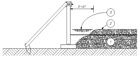
Figure 840.06-1 Backfilling for the First Row of Panels Only
(MSE wall systems that use steel soil reinforcement
or geosynthetic strips)
2. Connect the soil reinforcement and place an
8-inch (200 mm) loose lift of SGB on top of it (Item
2 in Figure 840.06-1). Place and compact
the SGB at least 3 feet (1.0 m) away from the facing
panels and moving parallel to the panels. Continue to place and compact the
lift of SGB with additional passes moving away from
the panels towards the free end of the soil reinforcement. See Figure 840.06-2.
3. Place SGB between
the initial row of facing panels and the previously placed SGB. Place the SGB in
one lift until it is about 8 inches (200 mm) above the soil reinforcement (Item
3 in Figure 840.06-1). Compact the
material with six passes of a mechanical tamper or vibratory plate compactor
that applies an impact or centrifugal force between ½ to 2 tons (0.6 to 2.2
metric tons). Do not perform compaction
testing on the material within 3 feet (1.0 m) of the facing panels.
4. Place and compact additional lifts of SGB at least 3 feet (1.0 m) away from the facing panels and
moving parallel to the panels. Continue to place and compact each lift of the SGB with additional passes moving away from the panels
towards the free end of the soil reinforcement.
See Figure 840.06-2.
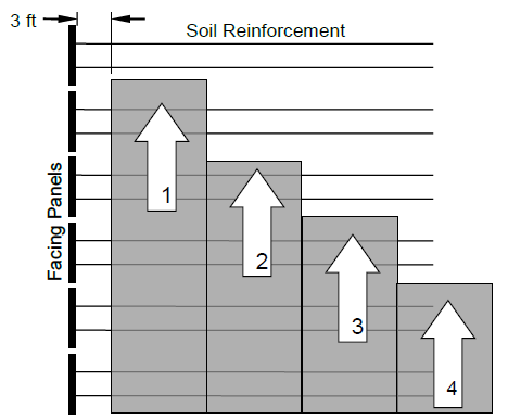
Figure 840.06-2 Procedure
for SGB Placement and Compaction (Plan View)
5. Place and compact SGB
in the 3-foot (1 m) area between the facing panels and the previous lift of SGB. Compact the
material with six passes of a mechanical tamper or vibratory plate compactor
that applies an impact or centrifugal force between ½ to 2 tons (0.6 to 2.2
metric tons). Do not perform compaction
testing on the material within 3 feet (1.0 m) of the facing panels.
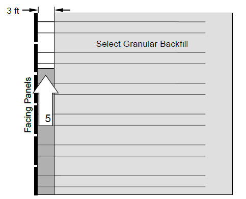
Figure 840.06-3 SGB Placement and Compaction Next to Facing Panels (Plan
View)
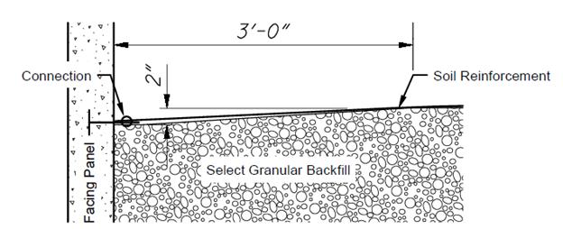
Figure 840.06-4 SGB at Connection
6. When the SGB reaches
the next layer of soil reinforcement, place the SGB
that is more than 3 feet (1 m) away from the facing panels to a level 2 inches
(50 mm) above the soil reinforcement connection. Slope the SGB that
is within 3 feet (1 m) of the facing panels as shown in Figure 840.06-4.
7. Repeat steps 4 through 6 until placement of
the SGB and soil reinforcements is complete.
Except as stated
otherwise in the procedure above, place and compact the SGB
as follows. Place the SGB in loose lifts no greater than 8 inches (200 mm) thick.
Compact SGB using a vibratory roller with a static
weight between 6 to 10 tons (7 and 11 metric tons). Operate compaction equipment in a direction
parallel to the facing panels. Test the compaction
according to Supplement 1015. Use either
Test Section Method A or B according to Supplement 1015 and 203.07. Sample the SGB
material and create a moisture density curve according to AASHTO
T 99, Method C for each type and source of material. Compact the SGB to
a minimum of 98 percent of the test section maximum dry density.
Do not disturb,
damage, or distort soil reinforcements, facing panels or joint coverings during
compaction.
At the end of each
day’s operations, shape the last lift of SGB to
direct rain water runoff away from the wall face. Prevent surface drainage from adjacent areas
from entering the wall construction site.
J. Pile
Sleeves. When piles are located within the reinforced soil zone, install pile
sleeves during MSE wall construction. Place the bottom of the sleeves at the bottom
of the SGB or at the bottom of the undercut whichever
is deeper. Maintain the vertical
alignment of the pile sleeve during construction of the MSE
wall. After driving the pile, place
granular fill into the sleeve around the pile in a uniform manner so there are
no unfilled voids within the pile sleeve.
K. Coping. Cast the coping
in place according to Item 511 and the plans.
If using anchors installed in precast panels to support the formwork for
the coping, ensure that the anchors are at least 6 inches (150 mm) from the
edge of the precast panel. Do not use
precast concrete coping. When the panels
have an aesthetic surface treatment, use expanding foam to fill the voids
between the facing panel and the forms for the coping. Remove any visible foam after the concrete
coping has cured.
L. Concrete
Sealing. Seal exterior surfaces of all panels and coping with an
epoxy-urethane sealer according to Item 512 after the completion of wall
construction. Do not damage the fabric
covering the panel joints when preparing the surface before applying the
sealer.
M. Natural
Soil Placement. Once the SGB and
the coping are completed, place the natural soil along the slope in 12-inch
(300 mm) loose lifts. The Department will
use 95 percent of the standard Proctor maximum dry density for compaction
acceptance.
N. Inspection
and Compaction Testing. Perform all of the work described in SS 878
Inspection and Compaction Testing as it pertains to MSE
walls. Hire compaction personnel
described in Section 878.02 of Supplemental Specification 878 Inspection and
Compaction Testing of Unbound Materials.
Provide a summary report of all inspections, compaction tests and
measurements every 2 weeks to the Engineer.
Include all inspections, measurements, compaction test forms, test
section data, failing tests and lots and moisture checks. Notify the Engineer when each lift is
complete and provide the compaction test data.
The Engineer will perform quality assurance (QA) density tests on every
fifth lift. Make the required correction
when QA tests fail.
840.07 On-Site Assistance. Have a
representative from the accredited MSE wall system
supplier provide on-site technical assistance for the number of days shown in
the contract. This is done to ensure
that the Contractor and the Engineer understand the recommended construction
procedures for the accredited MSE wall system.
840.08 Method of Measurement. The
Department will measure the Mechanically Stabilized Earth Wall by the number of
square feet (square meter). The
Department will determine the area of the MSE wall
from plan dimensions using a length measured along the outside of the uppermost
facing panels and a height from the top of the concrete leveling pad to the top
of the concrete coping. The Department
will not adjust pay quantities for variations in the concrete leveling pad
elevations required to accommodate actual panel placement.
The Department will measure Aesthetic Surface Treatment by the number of square feet (square meters). If all facing panels have an aesthetic surface treatment, the measurement for the aesthetic surface treatment will be the same as for the MSE wall. If the aesthetic surface treatment is applied to only a portion of the facing panels, then the Department will determine the area of Aesthetic Surface Treatment by the total area of the facing panels with the aesthetic surface treatment applied.
The Department will measure Natural Soil, Wall Excavation and SGB by the number of cubic yards (cubic meters) according to 203.09.
The Department will measure Foundation Preparation by the number of square yards (square meters).
The Department will measure the 6" Drainage Pipe Perforated and Non-Perforated by the number of feet (meters) installed and accepted. The Department will not measure the backfill or filter fabric for the drainage pipe for payment. Include this cost in the drainage pipe.
The Department will measure Concrete Coping by the number of feet (meters) as measured along the outside of the uppermost facing panels.
840.09 Basis of Payment. The
Department will pay for all of the work described in 840.03.G and 840.06.D
under Foundation Preparation.
The Department will pay lump sum Select Granular Backfill (SGB) Inspection and Compaction Testing as follows:
Upon approval of the project personnel 10%
Uniform Progress Payments 80%
Wall Completion 10%
The Department will pay for epoxy-urethane sealer, concrete traffic barrier and sealers placed on traffic barriers under separate pay items.
Payment for wall excavation includes dewatering and disposal of materials. If a separate pay item for Cofferdams and Excavation Bracing is not included in the Contract, the Department will pay for cofferdams and excavation bracing under the contract unit price for the MSE wall.
Payment for MSE wall includes facing panels, soil reinforcements, connection devices, bearing pads, joint covering, pile sleeves, leveling pads, and other items which do not have separate pay items but are necessary to complete the MSE wall.
The Department will pay for accepted quantities at the contract prices as follows:
Item Unit Description
840 Square Foot Mechanically Stabilized Earth Wall
(Square Meter)
840 Cubic Yard Wall Excavation
(Cubic Meter)
840 Square Yard Foundation Preparation
(Square Meter)
840 Cubic Yard Select Granular Backfill
(Cubic Meter)
840 Cubic Yard Natural Soil
(Cubic Meter)
840 Foot (Meter) 6" Drainage Pipe, Perforated
840 Foot (Meter) 6" Drainage Pipe, Non-Perforated
840 Foot (Meter) Concrete Coping
840 Square Foot Aesthetic Surface Treatment
(Square Meter)
840 Days On-Site
Assistance
840 Lump Sum SGB Inspection and Compaction
Testing
MSE Wall
Acceptance Letter
|
Project No. |
|
|
Wall No. |
|
|
Name of Accredited MSE Wall System |
|
|
Design Data |
|
|
Design Life |
100 years |
|
Angle of Internal Friction
– Reinforced Soil Zone |
34 degrees |
|
Actual Bearing Pressure at
base of reinforced soil mass |
|
|
Allowable Bearing Pressure
at base of reinforced soil mass |
|
We hereby certify that the
design calculations for the internal stability of the mechanically stabilized
earth retaining structure and the detail drawings included in this construction
submission are in complete conformance with the MSE
wall Supplemental Specification 840 and either the AASHTO
Standard Specifications for Highway Bridges, 17th Edition, 2002 or the AASHTO LRFD Bridge Design Specifications, 4th edition. We further certify that the design data
provided above and data assumed for the design calculation submitted herein is
accurate for the above referenced wall.
|
Engineer’s Seal |
|
Engineer’s Seal |
|
|
|
|
|
Signature: |
|
Signature: |
|
Date: |
|
Date: |
(Provide an MSE
Wall Acceptance Letter for each wall designated in the project plans.)