501.01 General
501.02 Verification of Dimensions
501.03 Notification of Fabricator
501.04 Shop Drawings
501.05 Submittal of Construction Plans
501.06 Test Reports
501.01 General. This specification includes the general requirements for building the various items that constitute the completed structure.
Perform the work, including fabrication, erection, and construction, so that the entire structure and all its component parts will function as designed.
501.02 Verification of Dimensions. Verify that all dimensions established by the Engineer are correct.
501.03 Notification of Fabricator. When furnishing materials under Items 513, 515, 516, 517, and 518, select a fabricator from the pre-qualified fabricators list in effect the date of the Contract letting. Before or at the preconstruction conference, provide a written notification to the DCE and Office of Materials Management of the selected steel fabricators and precast concrete fabricators.
501.04 Shop Drawings. Provide shop drawings detailing structural steel, metal structural elements, prestressed concrete members, precast concrete structural elements, and other similar materials requiring either shop or field fabrication according to AASHTO Standard Specifications for Highway Bridges and Item 501.
A. Contractor Acceptance of Shop Drawings for Items 513 and 515. After preparing the shop drawings for Items
513 and 515, submit the drawings to the Director at least 7 days before the
pre-fabrication meeting, or before the start of fabrication on Item 513, UF
Level. Department approval of these shop
drawings is not required.
Submit
four copies of the prepared shop drawings at least 40 days prior to the pre
fabrication meeting to each railroad company involved for review and
approval. Resolve all railroad comments
prior to supplying the letter of written acceptance to the Department. The
acceptance submission to the Department shall include one set of shop drawings
approved by each railroad company involved; copies of all documentation between
the railroad(s) and the Contractor; and four sets of
Contractor accepted shop drawings for each railroad company involved.
Include in the shop drawing submission a written acceptance letter and four copies of each drawing, unless additional copies are requested. For structures carrying railroad traffic, furnish 4 additional sets of shop drawings for each railroad company involved. Also, furnish the fabricator’s quality control specialist with one additional set of these drawings before the pre-fabrication meeting.
Prepare the shop drawings by or under direct supervisory control of an Ohio Registered Engineer having personal professional knowledge of AASHTO Standard Specifications for Highway Bridges, and Items 513 and 515. The Registered Engineer shall seal and date each drawing. Have all questions and comments addressed before submitting the shop drawings.
The Contractor’s written acceptance letter shall document acceptance of the shop drawings including confirmation of field verification, as required, and descriptions of issues resolved between the Contractor, the fabricator, or the Department.
By accepting these shop drawings, the Contractor represents to the Department that all dimensions and elevations of existing conditions shown on the plans have been field measured and verified, and that these shop drawings comply with all the materials requirements, construction requirements, contract requirements, and performance criteria. The Contractor further represents that these drawings have been coordinated and verified with the details of the work to be performed by other fabricators and entities on the project. The Department will not make any allowance for additional cost or delays to the Contractor for incorrect fabrication as a result of failure to coordinate or perform this acceptance.
If the Department requests changes on these shop drawings, or the Contractor makes changes in addition to those expressly requested, ensure that the shop drawings are accepted as above with suitable revision marks to identify the changes.
Schedule the pre-fabrication meeting after the Director receives the drawings. Fabrication may begin after the pre-fabrication meeting is complete or after receipt of Item 513, UF Level drawings.
B. Fabricator Coordination of Shop Drawings for Items 516, 517, and 518. The Contractor and fabricator must coordinate these shop drawings. Ensure that shop drawings meet requirements for materials, field measurements, construction requirements, contract requirements, performance criteria, and similar data. The coordination must also include details of the work to be performed by other fabricators and entities on the project. The Department will not make allowance for additional cost or delays to the Contractor for incorrect fabrication as a result of failure to coordinate or perform this coordination.
Submit two copies of the shop drawings to the Engineer with the materials delivered to the project. Do not incorporate material into the work until after submitting the drawings. Department approval of these shop drawings is not required.
C. Shop Drawing General Requirements. Specific requirements are specified in Item 513, 515, 516, 517, or 518.
Make the prints from tracings, neatly and accurately drawn on 22 ´ 34-inch (559 ´ 864 mm) sheets.
After all fabrication is completed for Item 513 and 515, furnish, to the Director, a copy of each final Contractor accepted shop drawing on a digital media storage device according to Supplement 1002. For structures carrying railroad traffic, furnish an additional digital media storage device or, at the option of each railroad, furnish a set of full-size drawings on Mylar.
501.05 Submittal
of Construction Plans and
Calculations. Do not begin work
until after complying with the acceptance criteria and work limitations specified
below.
Design and perform all
procedures as directed by the AASHTO Standard Specifications for
A. Prepare and provide
plans listed in this section as follows:
Have an Ohio Registered Engineer prepare, sign, seal and date each plan. Submit
plans that will be accepted to all involved railway companies at least 50 days
before construction begins. Obtain acceptance from all involved railroad
company(s). Furnish the Engineer with copies of all correspondence with the
railroad, documentation of railroad acceptance and the plans accepted by the
railroad. Department acceptance is not required.
This section applies to construction plans for the
following:
1. Sheeting and bracing of excavations adjacent to the
railroad tracks.
2. Demolition
of structures over or within 14 feet of railroad tracks.
3. Erection
of structural members over or within 14 feet of railroad tracks or that carry
railroad traffic.
B. Prepare and provide
plans listed in this section as follows:
Have an Ohio Registered Engineer prepare, sign, seal and date each plan. Have a
second Ohio Registered Engineer check, sign, seal and date each plan. The preparer
and checker are two different Engineers. Include the following statement on the
plans:
“This plan was prepared in compliance with
contract documents.”
Submit the plan to the Engineer at least 7 days before construction begins.
Department acceptance is not required.
This section applies to construction plans for the
following:
1. Sheeting and bracing adjacent to active traffic when
required by contract. Perform all work
as specified below:
a. Locate sheeting and bracing per contract.
b. Maintain temporary horizontal and vertical
clearances per contract.
c. Design sheeting or bracing to support the
roadbed including the effects of AASHTO live and dead load surcharges.
2. Demolition
of structures over or adjacent to active traffic. Perform all work as specified
below:
a. Provide
temporary devices or structures necessary to protect traffic during all
demolition activities. Provide traffic protection when demolition is located
less than 12' horizontally from active traffic on structures of less than 25'
vertical clearance. Increase the 12' minimum horizontal distance 1 foot for
each 2 feet of additional height greater than 25'.
b. Never
lift the portions of structure being removed over active traffic. Before
releasing traffic make the remaining structure stable.
c. Design
traffic protection devices or structures for a minimum load of 50 pounds per
square foot plus the weight of equipment, debris and any other load to be
carried. Include any portion of the deck that cantilevers beyond the fascia
beams or girders.
d. In lieu
of temporary devices or structures required in “a” above, provide a vertical
barrier. Design the vertical barrier with rigid or flexible materials
specifically designed for demolition containment. Extend the enclosure up to
the bottom of the deck and down to the ground. Maintain all materials free of
tears, cuts and holes.
e. Maintain
temporary horizontal and vertical clearances per contract.
f. Locate
structural members to be reused before performing any removal operations.
g. Do not
damage structural members being reused during any removal operation.
h. Perform
work so that all members are stable during all operation and loading
conditions.
i. Perform
work per 501.05.B.6.
3. Falsework
for cast-in-place concrete bridges over 20 feet (6.1 m) in span. Perform all
work per 508 and as specified below:
a. Provide
a camber table to account for the deflection of the falsework loaded with its self weight and the weight of
wet concrete. Also include in the table, the specified camber to compensate for
slab deflection after the falsework is released.
b. Maintain
temporary horizontal and vertical clearances per contract.
c. As a minimum
design falsework over waterways for a five year flood or with
75% of the effective waterway opening of the proposed structure. The Contractor is responsible for any damages caused by
upstream flooding due to insufficient temporary structure size or the
accumulation of debris or sediment in the channel.
d. Support
falsework foundations located within the ten year flood limits on rock, shale or piles driven
to a minimum depth of 15 feet, and to sufficient penetration to carry
superimposed loads or until refusal on rock.
4. Erection
of steel or precast concrete structural members as specified below:
a. Never
lift structural members over active traffic. Before releasing traffic make
structural members stable.
b. Supply
any temporary supports or braces necessary to maintain structural stability and
prevent lateral movement until completion of all construction activities.
c. Perform
work per 501.05.B.6, 513 or 515.
d. Do not
field weld temporary members to permanent steel members.
e. Maintain
temporary horizontal and vertical clearances per contract.
5. Jacking
and support of existing structures as specified below:
a. Support
the structure on temporary supports and brace as necessary to maintain
structural stability and prevent lateral movement until completion of the
permanent supports. Do not use jacks alone to support the structure except
during the actual jacking operation. Remove all temporary supports upon completion
of the jacking procedure.
b. Maintain
a maximum differential jacking height of 1/4 inch between any adjacent beam
lines.
c. Maintain
a maximum differential jacking height of 1 inch between any adjacent abutments
or piers.
d. Place
jacks and any load plates at least 2 inches from the edges of any concrete
substructure seats.
e. Do not
field weld temporary members to permanent steel members.
f. Maintain temporary horizontal and vertical clearances per contract.
6. Placing
or moving equipment having a gross weight in excess of 60,000 pounds (27,000
kg) on or across a structure as follows:
a. Do not
allow equipment having a gross weight in excess of the posted limit to be
placed on or driven across a structure.
b. Do not allow erection and construction methods, or use or move erection or construction equipment on or across the uncompleted or completed structure, to subject any part of the structure to unit stresses that exceed by more than one-third the allowable unit stresses, as given in AASHTO Standard Specifications for Highway Bridges.
7. Structures for maintaining traffic in accordance with Item 502.
a. For structures located over or within 14 feet of railroad tracks, submit plans in accordance with 501.05.A.
b. Perform
work per 501.05.B.6.
C. Welded
Attachments. Prepare and provide a
detailed request showing weld size, length, type and location for welding
permanent or temporary attachments to main structural members not shown or
permitted by contract. Submit request to the Office of Structural Engineering for acceptance at least 20 days
before construction begins. Perform work per 501.05.B.6 and 513.
501.06 Test Reports.
A. Contractor Acceptance of
Materials for Item 513. Submit certified test data to the Director
showing compliance with the requirements of Item 711. Accompany all certified test data with copies
of mill shipping notices or invoices showing the quantity and size of material
being accepted.
Check this
material data and provide a letter of written acceptance. Submit the material data and letter of
written acceptance to the Director so that the Director receives them at least
7 days before final shop inspection Item 513, Levels 1 through 6 or before
final shop inspection Item 513, UF Level.
Submit a
single copy of this material data for each structure, except where the
structure carries railway traffic.
Submit one additional copy to each railway company involved.
Additionally
for Item 513, Levels 1 through 6 structural steel members, submit one copy of
main material, certified test data with a letter documenting the QCFS
acceptance to the QA shop inspector before the material passes check point one.
The
Department will not accept materials for final inspection at the fabrication
shop until the Director receives the Contractor accepted
material data.
B. Fabricator Certification of Materials for Items 516, 517,
and 518. Ensure that a letter of certification
accompanies the fabricated material shipped to the job site, in a format
approved by the Director, stating all materials conform to contract
requirements. For these materials, the
fabricator must retain certified test data, copies of mill shipping notices, or
invoices showing the quantity and size of material being accepted. This data shall provide complete traceability
to the producing mill and proof of domestic origin, as required by ORC 153.011.
Do not
deliver materials to the project without the certification letter.
ITEM 502 STRUCTUREs for maintaining traffic
502.01 Description
502.02 Design and Construction
502.03 Maintenance
502.04 Removal
502.05 Basis of Payment
502.01 Description. This work consists of preparing plans, providing, maintaining, and subsequently removing temporary structures.
502.02 Design and Construction. As a minimum, design the temporary structure for a 5-year flood or with 75 percent of the effective waterway opening of the proposed structure. The Contractor is responsible for any damages caused by upstream flooding due to insufficient temporary structure size or the accumulation of debris or sediment in the channel. Provide a clear roadway width of at least 23 feet (7.0 m) measured from face to face of guardrails. If the existing structure or approaches or both have sidewalks provide at least one sidewalk at least 5 feet (1.2 m) wide with adequate connections to existing walks and in compliance with accessibility standards.
Design the temporary
structure according to the AASHTO LRFD Bridge Design Specifications except that the design live loading, HL-93 may
be reduced by 25 percent.
Submit construction plans in accordance with 501.05.
Drive piling to sufficient penetration to carry the superimposed loads according to Item 507, but not less than 24 tons (24 metric tons) per pile. Perform dynamic load testing to determine required blow count if piles are not driven to rock.
If the plans state that the existing superstructure may be used instead of new construction, do not alter it to meet either the above width or strength requirements. Instead, move or dismantle and re-erect with sufficient care to avoid any reduction of capacity. If the superstructure has been restricted by posting to loads less than permitted by statute, move the posting signs to the temporary road, unless the superstructure is strengthened to a legal load capacity. If planning to use the existing superstructure on the temporary road, notify the Engineer at least 3 days before the superstructure is moved to allow the Department to establish a detour. Complete the bridge within 48 hours after traffic has been routed over the detour.
502.03 Maintenance. Maintain all portions of the temporary structure in good condition with respect to both safety and smoothness for travel as long as it is needed for maintenance of traffic. Satisfactorily maintain the channel and waterway opening.
502.04 Removal. If the temporary structure is no longer needed, take ownership and remove it from the site according to Item 202.
502.05 Basis of Payment. Payment is full compensation for erection, maintenance, performing dynamic load testing, and subsequent removal of temporary structures.
The Department will pay for accepted quantities at the contract price as follows:
Item unit Description
502 Lump Sum Structure for Maintaining Traffic
ITEM 503 EXCAVATION FOR STRUCTURES
503.01 Description
503.02 Classification
503.03 Cofferdams, Cribs, and Sheeting
503.04 Protection for Excavation
503.05 Footings in Rock
503.06 Approval of Foundations
503.07 Disposal of Excavated Material
503.08 Backfill
503.09 Method of Measurement
503.10 Basis of Payment
503.01 Description. This work consists of designing cofferdams and shoring, and excavating materials not removed under other items of work that must be removed to enable construction of bridges, and other structures. Included in this work are:
A. constructing, maintaining, and subsequently removing cofferdams and shoring;
B. dewatering and backfilling the excavation;
C. protecting the excavation against collapse; and
D. disposing of materials not required or suitable for backfill.
503.02 Classification. Excavation is classified as unclassified excavation, unclassified excavation including rock (or shale), or rock (or shale) excavation.
503.03 Cofferdams, Cribs, and Sheeting. This item includes the preparation of a plan; the construction, maintenance, and subsequent removal of all cofferdams, cribs, sheeting, shoring, bracing, or other materials necessary to safely support the sides of excavations, embankments, adjacent buildings, tracks, or other premises; and all pumping necessary to complete required construction.
Construct cofferdams, cribs, and sheeting such that wales and crossbraces, if practical, clear the top of the footings by at least 1 foot (0.3 m). If this is not practical, construct this bracing using structural steel and leave it in place. If bracing is to be left in place and the ends would not be visible when the structure is completed, burn off the steel ends flush with the concrete surface. If ends would be visible, box back the steel ends at least 6 inches (150 mm) from the concrete face, and burn off the ends at least 3 inches (75 mm) back of the concrete face. Completely fill the resulting holes with concrete.
Where water is not encountered, the Contractor may place sheeting at the plan dimension of the footing and use it as forms for footing concrete. Leave this sheeting in place at least to the top of the footing, or properly separate it from the footing concrete so that it may be removed without damaging the concrete.
Where water is encountered, and cofferdams are necessary, construct them practically watertight before excavating below water level. Make provisions outside the footing to drain, collect, and remove water. When placing concrete, keep the excavation dewatered until the concrete is above the prevailing water level. Effectively protect footing concrete from erosion. If using a concrete seal to stop the flow upward from the bottom of a cofferdam, place the seal below the planned footing and consider it as a part of the cofferdam. The Department will not pay for a seal unless it is shown on the plans.
Design and construct
cofferdams, cribs, and sheeting to accommodate a water elevation 5 feet (1.5 m)
above the normal water elevation shown on the plans. If the actual water
elevation exceeds 5 feet (1.5 m) above the stated normal water elevation, the
Department will reimburse the Contractor for any resulting damage to the work
protected by the cofferdam provided the Contractor has exercised normal due
diligence. If the actual water elevation
exceeds 5 feet (1.5 m) above the stated normal water elevation and causes a
delay to the project, the Department will grant the Contractor an excusable,
non-compensable delay in accordance with 108.06.B.
Cofferdams may be
designed and constructed to accommodate a lower water elevation; however, the
Department will not reimburse the Contractor for repairs to work damaged nor
grant additional time unless the water elevation exceeds 5 feet (1.5 m) above
the normal water elevation shown on the plan.
Submit any request for reimbursement for repair to work damaged or for delay to the Engineer with information substantiating that the water elevation was more than 5 feet (1.5 m) above the normal water elevation shown on the plans.
503.04 Protection for Excavation. Cut the sides of all excavations to prevent caving, or protect the excavation from caving. Do not disturb the material below the bottom of footings. Perform blasting in a manner that avoids damage to the material supporting the structure vertically or laterally and that avoids subsequent slides that damage the structure, road, or adjacent property. If the material below the bottom of footings not supported by piles is disturbed, remove it and fill the entire space with concrete at no expense to the Department. Under footings supported on piles, replace and compact the over-excavated or disturbed material as the Engineer directs. If backfilling is necessary to correct caving or slides, backfill according to 503.09.
Excavation adjacent to railroad tracks are subject to the supervision of the involved railway company. Provide sufficient bracing to ensure the proper support of the roadbed and tracks.
503.05 Footings in Rock. Where rock or shale excavation is a separate pay item, fill the portion of the excavation into rock or shale that is below the top of footing with concrete.
If removing rock or shale as part of Unclassified Excavation and the footing is designed to be keyed into the bedrock, confine the excavation into bedrock for the minimum specified depth of keying within the area bounded by the outer edge of the footing. Fill excavation outside these limits and within and below the keyed depth with concrete.
503.06 Approval of Foundations. Notify the Engineer when the excavation is to be completed to the depth shown on the plans. Do not place footings until the Engineer has approved the subfoundation.
503.07 Disposal of Excavated Material. Dispose of excavated material not needed or not suitable according to 105.16 and 105.17. Use other suitable excavation material for backfill.
503.08 Backfill. Backfill under this item includes all replaced excavation and new embankment adjacent to structures. Use backfill embankment materials conforming to 203.02.R, except behind the abutments below the approach slabs use material conforming to Item 203 Granular Material Type B. Place and compact the backfill materials according to 203.06 and 203.07, except as modified by this subsection.
Do not place backfill material against any structural element until the Engineer has approved the element.
In bridge abutment areas compact backfill material to meet the compaction requirements in 203.07. Elsewhere, compact backfill material to 95 percent of the maximum laboratory dry density.
When a test section method is used for compaction acceptance: Use compaction equipment with a total weight or a centrifugal force of least 1 ton (0.9 metric tons). Supply the manufacturers’ information to verify this information. Use at least six passes to construct the production areas. Use at least 97 percent of the test section maximum dry density for acceptance of the production areas.
The Contractor does not have to place backfill material around piers that are not within the embankment area or adjacent to a roadway or a railway in thin layers or compact it, but should leave the backfill material in a neat condition with a compensating allowance made for settlement.
Backfill in front of abutments and around piers to the ground lines shown on the plans.
Backfill all structural foundation units as soon as practical after the required conditions of this subsection are met to avoid the ponding of surface water and the accumulation of debris. Simultaneously backfill in front of and behind abutments, piers, wing walls, and retaining walls.
Carefully backfill against waterproofed surfaces to avoid damage to the waterproofing material.
503.09 Method of Measurement. After the requirements of Items 201, 202, and 203 have been met, the Department will measure excavation by the number of cubic yards (cubic meters) as follows:
A. Bounded on the bottom. Bounded bottom plane of the footing, crossbeam, or wall.
B. Bounded on the top.
1. In cut sections, by the surface of the remaining ground.
2. In fill sections:
a. If excavation is performed before embankment is placed, by the surface of the original ground.
b. If excavation is performed after embankment is placed, by the surface of the embankment.
C. Bounded on the sides.
1. For Unclassified Excavation, 1 foot (0.3 m) outside the outer edge of the footing, crossbeam, or wall.
2. For Rock Excavation or Shale Excavation:
a. If Rock Excavation is included in the Contract, by the outer edge of the footing or wall.
b. If rock or shale is removed as part of Unclassified Excavation Including Rock and/or Shale:
(1) Above the minimum specified depth of keying, the same as described in 503.09.C.1.
(2) For the remainder of the excavation, the same as described in 503.09.C.2.a.
For abutment excavation quantities, the Department will include material removed above the bench (if any), in front of the vertical plane described in 503.09.C.1, and by the finished slope of the cut or embankment.
For keys below footings, the Department will determine the volume of keys by the number of cubic yards (cubic meters) shown on the plans.
The Department will measure Unclassified Excavation on a lump sum basis when shown on the plans.
The Department will measure Cofferdams, Cribs, and Sheeting on a lump sum basis.
503.10 Basis of Payment. If Cofferdams, Cribs, and Sheeting is not included in the Contract, the Department will pay for cofferdams, cribs, and sheeting under the contract unit price for excavation.
The elevations shown on the plans for the bottoms
of footings are considered as approximate.
When excavation below plan elevation for footings is required, the
Department will pay for the 3 feet (0.9 m) immediately below the plan elevation
within the lateral limits described in 503.09.C.1 at the unit price bid for the
class of excavation.
The Department will consider
additional excavation to a maximum depth of 3 feet (0.9 m) within the lateral
limits described in 503.09 as incidental to the lump sum price. Excavation deeper than 3 feet (0.9 m) below plan
elevation may be provided for as Extra Work, as described in 109.04.
If Cofferdams, Cribs, and Sheeting is a separate pay item, the lump sum price includes any extra cost involved for cofferdams for additional depth up to 3 feet (0.9 m) below plan elevation. Excavation deeper than 3 feet (0.9 m) below plan elevation and the additional cofferdams necessitated by this excavation may be provided for as Extra Work, as described in 109.04.
The Contractor shall provide additional fill material and subsequent excavation to provide the minimum cover over culverts to accommodate heavy earth moving equipment at no expense to the Department.
The Department will pay for accepted quantities at the contract prices as follows:
Item unit Description
503 Lump Sum Cofferdams, Cribs, and Sheeting
503 Cubic
Yard Unclassified
Excavation
(Cubic Meter)
503 Lump Sum Unclassified Excavation
503 Cubic
Yard Unclassified
Excavation Including Rock
(Cubic Meter)
503 Cubic
Yard Unclassified
Excavation Including Shale
(Cubic Meter)
503 Cubic
Yard Unclassified
Excavation
(Cubic Meter) Including Rock and/or Shale
503 Cubic
Yard Rock Excavation
(Cubic Meter)
503 Cubic
Yard Shale Excavation
(Cubic Meter)
ITEM
504.01 Description
504.02 Materials
504.03 Driving
504.04 Method of Measurement
504.05 Basis of Payment
504.01 Description. This work consists of furnishing and driving steel sheet piling to be left in place, including furnishing and installing any specified anchors or other attachments to structures.
504.02 Materials. Furnish new sheet piling conforming to 711.03. The Contractor may use used sheet piling in good condition that conforms to project requirements provided it is inspected and approved by the Engineer.
504.03 Driving. Drive steel sheet piling to the tip elevation shown on the plans.
504.04 Method of Measurement. The Department will measure Steel Sheet Piling Left In Place [Minimum Section Modulus of ____ cubic inches per foot (____ mm3/m)] of Wall by measuring the number of square feet (square meters) in the plane of the face of the sheeting, completed and accepted in place.
504.05 Basis of Payment. The Department will pay for accepted quantities at the contract price as follows:
Item unit Description
504 Square
Foot Steel Sheet
Piling Left In Place [Minimum
(Square Meter) Section Modulus of____ cubic
inches
per
foot (____ mm3/m)] of Wall
ITEM 505 PILE DRIVING EQUIPMENT MOBILIZATION
505.01 Description
505.02 Basis of Payment
505.01 Description. This work consists of mobilizing pile driving equipment to and from the project site and, as necessary, to install the required piling.
This work includes the fixed costs that are related to the installation of the required piling.
505.02 Basis of Payment. The Department will pay for accepted quantities, after the first service pile is installed, at the contract price as follows:
Item unit Description
505 Lump Sum Pile Driving Equipment Mobilization
506.01 Description
506.02 General
506.03 Application of Load
506.04 Basis of Payment
506.01 Description. This work consists of applying a static load to a driven pile and furnishing instruments and facilities to obtain load-settlement data required to determine the ultimate bearing value of the pile. The Director will when specified determine whether subsequent static tests are to be performed and the location of all piles to be tested.
506.02 General. Use the hammer selected for driving the test pile to drive all piles represented by the test. If the Contractor finds it necessary to use a different hammer, the Director will determine if an additional static load test is necessary.
If using anchor piles to apply load, locate piles not closer than 7 feet (2.1 m) center-to-center from the loaded pile. If possible, install anchor piles parallel to the axis of the loaded pile. The Contractor may use battered piles as anchor piles; provided the horizontal forces in the anchor system are balanced and excessive bending stresses are not induced in the piles. The Contractor may also use bearing piles meeting these requirements as anchor piles. After the test has been completed, remove or cut off at least 1 foot (0.3 m) below the bottom of the footing or finished surface of the ground all anchor piles outside the limits of the footing. Cut off anchor piles, other than bearing piles, within the limits of the footing 3 inches (75 mm) above the bottom of the footing. Redrive all bearing piles used as anchor piles that are displaced upward during the application of the test load according to the plan requirements.
Furnish a calibrated load cell to determine the load applied and a recent verification of the calibration of the gages and devices by a reliable agency equipped to do the testing.
For the duration of the test, provide adequate facilities to record load and settlement readings 24 hours per day. To avoid column buckling of the pile, ensure that tested piles are substantially vertical and that the load is applied to the pile at a point as near the ground surface as possible.
Determine if piles on the plan order list for cast-in-place reinforced concrete piles have a shell wall thick enough to withstand the maximum required static test load of twice the ultimate bearing value. The minimum wall thickness to support twice the ultimate bearing value is:
![]()
![]()
Where:
t = shell wall thickness in inches (mm)
R = ultimate bearing value in pounds (N)
D = diameter of pile in inches (mm)
If the shell wall for the test pile is less than t, before performing the static load test, either drive a test pile with a thicker shell wall, or fill the pile with concrete and allow the concrete to cure for 5 days. The test is unsatisfactory if the pile fails internally during the test due to improper installation or procedure by the Contractor.
506.03 Application of Load. Apply the load at least 5 days after placing concrete in the pile or 72 hours after driving both the pile to be tested and the anchor piles.
Apply a concentric load using a method that allows definite determination and control of the load acting on the pile at all times. Furnish a backup system for measuring the settlement of the pile being tested.
For the initial loading, use approximately one-fifth of the plan ultimate load. For subsequent loadings, use increments of approximately one-tenth the plan ultimate load, and apply these increments 1 hour after all measurable settlement due to the loading has ceased. Measurable settlement is defined as 0.01 inch (0.3 mm) or more in a 20-minute time interval.
The Engineer will record all settlement readings.
Apply the load until the load to the test pile reaches two times the plan ultimate load or until reaching the load test ultimate capacity of the pile plunging failure. Plunging failure is defined as a settlement rate of 0.03 inch per ton (0.8 mm/9000 N) for the load increment applied.
To determine the test load ultimate bearing value (Q), first plot the settlement versus load on the pile. Next, draw a line parallel to the slope line through the zero (O) point and the 0.2R load value but offset by the settlement formula, 0.15 inch + 0.008D (3.8 mm + 0.008D). The ultimate bearing value (Q) is the load corresponding to where the offset slope line crosses the plot.

If plunging failure is reached before the total applied load exceeds 1.5 times the plan ultimate load, apply an additional increment of load to ensure that the failure load has been established. If the amount of settlement per increment is repeated or increased, stop applying the load. If the amount of settlement per increment is not repeated or increased, continue applying the load increments until the pile’s ultimate capacity is reached or until a total load of two times the plan ultimate load is applied. If the pile’s load test ultimate capacity has not been reached after applying the last required load increment, continue applying the total load for at least 1 hour after all measurable settlement has ceased. Unload the pile in 25 percent decrements every 5 minutes.
The Engineer will continue to obtain settlement recovery measurements for 3 hours after totally unloading the pile.
If it is necessary to remove and reapply the load, use the same procedures to apply the initial loads except apply load increments 15 minutes after all measurable settlement has ceased.
506.04 Basis of Payment. If the Contractor subsequently finds it necessary to use a different hammer, the Director will determine if an additional static load test is necessary; the Contractor shall complete any such additional test at no additional cost to the Department.
The cost of furnishing the thicker shell wall test pile is included under Static Load Test.
The Department will pay for accepted quantities at the contract prices as follows:
Item unit Description
506 Lump Sum Static Load Test
506 Each Subsequent Static Load Test
507.01 Description
507.02 General
507.03 Materials
507.04 Driving of Piles
507.05 Determination of Required Blow Count
507.06 Cast-in-Place Reinforced Concrete Piles
507.07 Steel H-Piles
507.08 Timber Piles
507.09 Splices
507.10 Defective Piles
507.11 Prebored Holes
507.12 Method of Measurement
507.13 Basis of Payment
507.01 Description. This work consists of furnishing and driving bearing piles.
507.02 General. Install piles of the specified type, length, and sizes shown on the plans. Furnish the piles according to the itemized order list shown on the plans. If additional length is needed to obtain bearing, furnish the additional length as determined by the Engineer. The length of the piles given in the order list is not necessarily based on available or practical lengths, but the estimated length from the bottom of each pile to the elevation of the cutoff. The Contractor may increase or decrease the pile lengths to suit the lengths available, to facilitate the method of operation, which may involve providing fresh heading as a result of hammer misalignment or a worn hammer cushion, or to provide lengths determined practical to have delivered to the project site and driven.
507.03 Materials. Furnish materials conforming to the following:
Reinforcing steel........................................................... 509
Concrete, Class C......................................................... 511
Chemical admixture for concrete, Type F............... 705.12
Steel H-piles............................................................ 711.03
Steel pile points...................................... 711.01 or 711.07
Galvanized steel...................................................... 711.02
Timber..................................................................... 711.26
The material properties for the metal shells of cast-in-place reinforced concrete piles are not specified. Provide mill certifications showing domestic origin.
Provide a concrete slump from 6 to 8 inches (150 to 200 mm) with the use of a superplasticizer.
507.04 Driving of Piles. Drive piles to refusal on bedrock; until obtaining the required ultimate bearing value, which may include a modification for scour, set-up, or negative skin friction; or to the minimum penetration pile tip elevation shown on the plans.
If piles begin to crush, immediately cease driving and repair or replace the pile. The counting of blows will cease until the crushed pile is either repaired or replaced.
If bearing capacity is obtained before the pile has penetrated 80 percent of its estimated depth, notify the Director before appreciably overdriving the pile. The Director will study the conditions and determine the final penetration, the driving requirements, the use of another pile type, and the use of prebored holes.
All piles raised during the driving of adjacent piles shall be driven down again.
Use a hammer that will achieve the required
ultimate load for the pile with a blow count of at least 30 blows per foot (100
blows per meter) and large enough to permit a dynamic load test to verify that the ultimate bearing capacity shown on
the plans can be achieved.
The ram of an air-operated or diesel hammer shall weigh at least 2700 pounds (12,000 N).
The ram of a drop hammer for permanent piles shall weigh at least 3000 pounds (13,300 N). The height of fall for drop hammers shall not exceed 7 feet (2.1 m). Do not use drop hammers to drive piles that are to be driven to an ultimate load in excess of 70 tons (620 kN).
When using open ended diesel hammers, provide equipment for the Engineer’s use to accurately measure each stroke within 6 inches (150 mm).
Attach a gage to closed end diesel hammers, accessible to the Engineer, to monitor the pressure in the bounce chamber. Include a graph with the gage to convert pressure to energy.
Attach an impact energy monitor, or a method to accurately measure the stroke within 2 inches (50 mm) to hydraulic hammers, accessible to the Engineer, to monitor the energy of each blow.
Use securely anchored driving leads and a cap device with sliding jaws to engage the leads to guide the pile and maintain the pile alignment with the stroke of the hammer. Accurately align the travel of the hammer with the axis of the pile.
Cushion the hammer and pile to prevent the impact of driving forces from damaging the top of the pile. Shape the cap and pile top to uniformly distribute the hammer blow to the top surface of the pile.
Do not use a follower unless approved by the Director. If the Director does approve the use of a follower, make an allowance for the increased energy loss.
If a static load test is required, the Contractor may not drive piles except the test and anchor piles before conducting the test and the required depth of penetration has been determined.
Do not use water jets.
After being driven, cut off the piles at the elevation and angle shown on the plans.
507.05 Determination of Required Blow Count. Determine the required blow count to achieve the ultimate bearing value of a driven pile as if the pile was a single isolated pile using the results of dynamic pile testing as specified in Item 523.
507.06 Cast-in-Place Reinforced Concrete Piles. Provide cast-in-place reinforced concrete piles conforming to one or more of the types described below. Measure the pile diameter as follows:
A. Plain cylindrical casing, the outside diameter.
B. Cylindrical casings with vertical fluting, the diameter of a circle circumscribing the outermost points or ridges.
C. Cylindrical casing with circumferential corrugations, the average of the outside diameters measured at the bottom and top of the corrugations or continuously welded helical corrugations with diameters measured at tops of the corrugations.
D. Tapered piles, the top diameter as determined in 507.06.A, 507.06.B, or 507.06.C, but the pile tip diameter shall not be less than 8 inches (200 mm).
Ensure that the pile casings are water tight after being driven. If furnished, shoes or points shall not project more than 1/4 inch (6 mm) outside the vertical surface of the casing.
For plain cylindrical casings, the minimum pile wall thickness, t, is the greater of either 0.250 inches (6.66 mm) or the thickness determined using the following formula:
![]()
![]()
Where:
R = Ultimate bearing value in pounds (newtons) corresponding with the ultimate bearing capacity as shown on the plans
For fluted piles, the minimum pile wall thickness shall be t/1.4.
For cast-in-place piles containing reinforcing
steel, place reinforcing steel as stated in the second and third paragraph of
524.09 and place concrete per 524.11.
After installation, cover the tops of driven
casings, until the concrete is placed.
Before placing concrete, remove accumulated water or other foreign
matter in a driven casing. Maintain a
minimum radius of 15 feet (4.5 m) between simultaneous work of placing concrete
and driving pile casings. If concrete is
placed within the 15-foot (4.5 m) radius, suspend driving operations until the
concrete has cured for 5 days. Place
concrete for cast-in-place piles using methods that prevent voids, however, do
not vibrate the concrete.
507.07 Steel H-Piles. Steel H-piles shall consist of
structural steel shapes of the kind and size specified.
The Engineer may allow installation of steel piles of the specified type,
which the Contractor has from previous projects or stock, if the
Contractor furnishes mill certifications and the pile sections are identified
with the material specification number, grade, and heat number. This identification may be in the form of
information painted on the steel piles or a tag physically attached to the
steel.
507.08 Timber Piles. Provide timber piles of
sufficient length to remove broomed or split portions caused by driving. Symmetrically trim piles right truncated cone
at the tip. If steel shoes or points are
specified, carefully shape the tip of the pile so that the steel shoe or point
fits snugly and symmetrically.
Handle and store timber piles to prevent warping.
If specified, provide creosoted piles conforming
to 712.06.
507.09 Splices. To the fullest extent
practical, avoid splicing steel casings and structural shapes. Splice pile casings and structural shapes
either before or after driving a segment.
If spliced after driving a segment, splice the piles at least 3 feet
(1 m) above the ground and inspect the splice while the pile is driven a
minimum of 150 blows.
Align segments to make the axis of all segments
common.
Use full penetration butt welds to splice structural
shapes according to 513.21, except delete the requirement to use temporary extension
bars.
Do not splice timber piles.
507.10 Defective Piles. Piles entirely underground are
defective if the pile location at the ground surface is more than the 1 foot
(0.3 m) from the location shown on the plans.
Piles projecting above the ground are defective if
the pile location at the ground surface is more than 3 inches (75 mm) from the
location shown on the plans.
Pipe piles are defective if not water tight or if damage reduces the cross-sectional area by more than 20 percent. Provide the Engineer with a light that allows inspection of the entire length of the interior of a driven casing.
Replace, repair, or drive a substitute pile beside the defective pile. The location tolerance for underground piles does not apply to substitute piles beside defective underground piles. The off-location limits do apply to the substitute pile that project above the ground. If a defective pile is removed, fill the hole remaining in the ground with sand. Cut off a defective pile left in place under a footing 3 inches (75 mm) above the elevation of the bottom of the footing. Cut off a defective pile left in place but not under a footing at least 1 foot (0.3 m) below ground level. Fill defective pipe piles left in place with concrete.
When the outside rows of bearing piles are not located within tolerances specified above, increase the size of the footing to provide a minimum distance between the pile and footing edge of at least 75 percent of that shown on the plans.
507.11 Prebored Holes. Locate prebored holes as shown on the plans. Provide augured hole diameters:
A. For round piles, from 2 inches (50 mm) less to 4 inches (100 mm) more than the pile diameter.
B. For steel H-piles, from 6 inches (150 mm) less to 2 inches (50 mm) more than the pile’s diagonal dimension but shall be such as to produce satisfactory pile driving results. Backfill voids between the pile and the prebored hole with a granular material satisfactory to the Engineer.
507.12 Method of Measurement. The Department will measure piles driven by the number of feet (meters). The Department will determine the sum as the lengths of all non-defective piles measured along the axis of each pile from the bottom of each pile to the elevation of cutoff. Unless a separate pay item is specified in the Contract, the Department will include Steel Points or Shoes in the measured length of driven piles. If a separate pay item is specified in the Contract, the Department will measure Steel Points or Shoes by the number of each.
The Department will measure piles furnished by the number of feet (meters) of plan specified order length plus any additional order length specified by the Engineer. The Engineer will include the length of undriven piles as furnished, but the Contractor will not receive additional compensation for hauling the piles off the project.
For plan specified prebored holes, the Department will measure Prebored Holes by the number of feet (meters) of prebored hole lengths for non-defective piles measured from the surface of ground at the time of boring to the bottom of the hole. The Department will not measure preboring to facilitate the pile driving operation.
The Department will measure steel pile splices by the number of splices authorized by the Engineer to lengthen non-defective piles beyond the plan specified length. Instead of plan specified steel pile splices, the Contractor may choose to furnish steel piles longer or shorter than the plan specified pile order lengths.
507.13 Basis of Payment. Preboring to facilitate the pile driving operation is included in the unit price bid for piles driven.
The Department will consider the cost of
furnishing and installing the reinforcing steel to be included in the unit
price bid for piles driven.
The Department will not pay for any splices due to the Contractor furnishing pile lengths shorter than plan order lengths.
The Department will not pay for increased pile lengths made by the Contractor unless the Engineer determines that the additional lengths are needed to achieve bearing.
If additional penetration is necessary in order to achieve the required bearing, the Department will pay for required splices at a negotiated price.
The Department will pay for accepted quantities at the contract prices as follows:
Item unit Description
507 Foot (Meter) Steel Piles HP____´____, Furnished
507 Foot (Meter) Steel Piles HP____´____, Driven
507 Foot (Meter) ___" (___ mm) Cast-In-Place,
Reinforced Concrete Piles, Furnished
507 Foot (Meter) ___" (___ mm) Cast-In-Place,
Reinforced Concrete Piles, Driven
507 Foot (Meter) Timber Piles, Creosoted
507 Foot (Meter) Timber Piles, Untreated
507 Foot (Meter) Prebored Holes
507 Each Steel Points or Shoes
508.01 Description
508.02 Falsework
508.03 Forms
508.04 Oiling Forms
508.05 Basis of Payment
508.01 Description. This work consist of designing and building of falsework and forms for the purpose of holding concrete in place until it has set up.
508.02 Falsework. Provide substantial and rigid falsework that does not unduly obstruct any waterway, highway, or railway. Arrange intermediate supports in the completed structure to produce the camber necessary to conform to the plan profile of the roadway.
Do not allow the maximum deflection in the longitudinal falsework members at the edges of the concrete deck to exceed 1/2 inch (13 mm) or the amount obtained by the following formula, which ever is greater.
![]()
![]()
where:
d = the maximum deflection in inches (millimeters)
S = the distance between supports in inches (millimeters)
For transverse falsework members, and for longitudinal falsework members other than those near the edges of the deck, increase the permissible deflection obtained from the above formula by 75 percent. If, due to vertical clearance or spanning an existing road or channel, unusual requirements exist, the Director may approve falsework with excessive deflection.
To compensate for falsework deflection, build camber into the falsework. In addition to falsework defection, build the following amounts of camber into the falsework to compensate for slab deflection after falsework is released:
A. Equal to 1/800 of the span for continuous spans.
B. Equal to 0.000018 S3 (0.016 S3) for simple spans, where S is the length of the slab span in feet (meters) for camber expressed in inches (millimeters).
Provide camber to conform to the profile grade. If, due to vertical clearance or spanning an existing road or channel, unusual requirements exist, the Director may approve falsework with excessive deflection provided the concrete properly reforms.
If the falsework does not rest in rock, shale, or other firm foundation material, support falsework on piling driven to sufficient penetration to carry the superimposed loads according to Item 507, but not less than 16 tons (16 metric tons) per pile. Perform dynamic load testing to determine required blow count if piles are not driven to rock. Do not use expansion anchors to support falsework on piers or abutments. Use double hardwood wedges as necessary to facilitate vertical adjustment.
Remove and replace any part of the structure made unsatisfactory by incorrect camber, settlement or form deformation.
Construct falsework for arches so it may be released gradually.
Remove falsework only after the concrete conforms to 511.16 and before final acceptance of the structure. Cut off or pull falsework piling. Cut off piles to at least the slope line, riprap line, or stream bed.
Locate the lower contact point of overhang
falsework within 8 inches (200 mm) of the top of the
rolled beam or steel girder’s bottom flange.
For bridges over 20-foot (6.1 m) span whose main supporting members are cast-in-place concrete, submit falsework plans according to 501.05.
If a thickened edge is shown on the plans, the Contractor may develop the edge by sloping the bottom of the slab for a minimum of 9 feet (2.7 m) from the edge, instead of the section shown.
Do not place spandrel walls, decks of arches, sidewalks and curbs, or any superimposed concrete to be completed after constructing the main supporting member or the deck until the falsework for the main supporting member has been removed or released.
For continuous concrete slab or beam superstructures, do not place concrete on a span until the falsework and forms are complete for the adjacent spans. Do not release or remove falsework from a span until the concrete in adjacent spans has been placed a sufficient length of time to meet all requirements for the removal of falsework as set forth in 511.16.
508.03 Forms. Place all concrete in proper forms. Do not use unprotected sides of the excavation, instead of forms, unless as specified in 503.04 for rock or hard shale excavation. For dry excavation specified in 503.03, the Contractor may use the sheeting as forms for footings.
Construct substantial, unyielding, and mortar tight forms, designed to produce a finished concrete conforming to the proper dimensions and contours. Make forms for exposed surfaces of approved material requiring a minimum number of joints or of dressed lumber of uniform thickness using form liner approved by the Engineer. Use forms and form liners to reduce the joints showing on the finished surface to a minimum. Arrange joints to coincide with rustication grooves shown on the plans. Properly brace or tie forms together using approved form ties that do not allow metal within 2 inches (50 mm) of an exposed surface of the finished structure after the forms are removed. For ties in the region of exposed surfaces, use an approved insert. Remove all forms and do not allow material, except reinforcing supports specified in 509.08, to remain in the concrete.
For concrete decks separated by an open median or temporarily separated by a closure section, construct falsework and forms for each deck or section of deck independent of the adjacent structure or remaining superstructure.
Immediately before placing concrete, provide temporary openings at the base of column and wall forms and in the bottom of all narrow, deep members where necessary to facilitate cleaning or inspection.
Provide a 3/4-inch (20 mm) bevel on all exposed edges using a triangular strip built into the forms.
If rustication is used, fasten molding that is
surfaced on all sides to the forms in such a manner that the molding remains in
the concrete when the forms are removed.
Do not remove this molding until the concrete has set sufficiently to prevent
damage to the edges of the concrete.
If weep
holes through abutments or retaining walls are shown on the plans, form weep
holes to obtain a smooth circular opening between 3 and 4 inches (75 and 100
mm) and a straight gradient of 0.08 through the wall.
508.04 Oiling Forms. Before placing reinforcing
steel, coat the inside of forms with non-staining mineral oil or other approved
material.
508.05 Basis of Payment. The Department will not separately pay for falsework and forms.
The cost of this work is included for payment in the price bid for the
item for which falsework and forms are used.
The Department will not pay for removal and
replacement of any part of the structure made unsatisfactory by settlement or
form deformation.
The Department will not pay for dynamic load
testing required to determine blow count if piles are not driven to rock.
509.01 Description
509.02 Materials
509.03 Care of Material
509.04 Method of Placing
509.05 Bending
509.06 Approval of Placing
509.07 Splicing
509.08 Supports
509.09 Epoxy Coated Reinforcing Steel
509.10 Method
of Measurement
509.11 Basis of Payment
509.01 Description. This work consists of furnishing and placing supports, mechanical connectors, tie wires, and reinforcing steel of the quality, type, size, and quantity designated, including steel dowels.
509.02 Materials. Furnish materials conforming to:
Epoxy coated reinforcing steel................................ 709.00
Reinforcing steel,
.... deformed bars........................... 709.01, 709.03, 709.05
Spiral reinforcing steel............................. 709.01 or 709.08
Bar mats and wire fabric................ 709.09, 709.10, 709.12
Plastic supports...................................................... 709.15
For metal bar supports used at or near the surface of the concrete, furnish either galvanized steel, stainless steel, epoxy coated steel or plastic coated steel.
Provide sufficient additional reinforcing steel to replace reinforcing steel removed by the Department for sampling. Replace random samples in the structures with additional steel, spliced according to 509.07.
When providing reinforcing steel for spiral cages, galvanized steel conforming to ASTM A767, Class 1, may be provided only for the spiral reinforcing steel in lieu of epoxy coated reinforcing steel. The galvanized coated reinforcing steel will meet all other requirements of 509. Where a sample splice is needed use the lap length requirements for epoxy coated. The Galvanized coating will be applied after the reinforcing has been fabricated. If the galvanized surface becomes damaged during handling in the field, repairs will conform to ASTM A780. Use bar supports and tie wires which are plastic coated or epoxy coated. Only suppliers certified under S1068 may provide this reinforcing.
509.03 Care of Material. Upon delivery to the project and before use, stack reinforcing steel off the ground and keep it free from dirt, oil, grease, or avoidable rust. Before placing in the concrete, ensure the reinforcing steel is clean and free of loose rust.
509.04 Method of Placing. Place reinforcing steel in the positions shown on the plans, and firmly secure the steel during the placing and setting of concrete. Tie bars in the superstructure at all intersections, except tie bars at alternate intersections where bar spacing is less than 1 foot (0.3 m) in any direction. The Contractor may place up to 25 percent of the upper longitudinal bars in a bridge deck slab beneath the upper transverse bars to support the top mat. Do not drive or force reinforcing steel into concrete after its initially set.
Welding on reinforcing is prohibited, except as permitted by 709.10 and 709.12. The Engineer will allow the Contractor to fabricate reinforcing bar cages for prestressed beams if fabrication is done in a manner satisfactory to the Director.
Install reinforcing steel with at least the following clearances from the concrete surface:
A. 2 1/2 inches (65 mm) to the top of sidewalks.
B. 3 inches (75 mm) at the faces of footings placed against rock or earth.
C. 1 1/2 inches (38 mm) to the bottom of a cast-in-place deck slab.
D. 2 inches (50 mm) at all other surfaces.
E. 2 1/4 to 2 1/2 inches (60 to 65 mm) between the reinforcing steel and the top surfaces of cast-in-place concrete deck slabs.
509.05 Bending. Bend reinforcing steel to the dimensions shown on the plans and in Table 509.05-1 (509.05-1M). Reject reinforcing steel showing transverse cracks.
TAble 509.05-1 STANDARD BENDS
|
|
Bar |
|
|
|
|||||
|
|
Nominal Dimensions |
180° |
90° |
135° |
|||||
|
Bar |
Diameter |
Area |
Weight |
D |
A |
D |
A |
D |
A |
|
Size |
in |
in2 |
lb/ft |
in |
in |
in |
in |
in |
in |
|
3 |
0.375 |
0.11 |
0.376 |
2 1/4 |
5 |
2 1/4 |
5 |
1 1/2 |
4 |
|
4 |
0.500 |
0.20 |
0.668 |
3 |
6 |
3 |
7 |
2 |
4 1/2 |
|
5 |
0.625 |
0.31 |
1.043 |
3 3/4 |
7 |
3 3/4 |
8 1/2 |
2 1/2 |
5 1/2 |
|
6 |
0.750 |
0.44 |
1.502 |
41/2 |
8 |
4 1/2 |
10 |
|
|
|
7 |
0.875 |
0.60 |
2.044 |
5 1/4 |
10 |
5 1/4 |
12 |
|
|
|
8 |
1.000 |
0.79 |
2.670 |
6 |
11 |
6 |
131/2 |
|
|
|
9 |
1.128 |
1.00 |
3.400 |
9 1/2 |
15 |
9 1/2 |
15 1/2 |
|
|
|
10 |
1.270 |
1.27 |
4.303 |
10 3/4 |
17 |
10 3/4 |
18 |
|
|
|
11 |
1.410 |
1.56 |
5.313 |
12 |
19 |
12 |
20 |
|
|
|
14 |
1.693 |
2.25 |
7.65 |
18 1/4 |
27 |
18 1/4 |
25 |
|
|
|
18 |
2.257 |
4.00 |
13.60 |
24 |
36 |
24 |
33 |
|
|
|
Tolerances: For
diameter of bends, “D”, the tolerance may be plus or minus the diameter of
the bar. Standard fabricating
tolerances shall be in accordance with the CRSI Manual of Standard
Practice. No weight allowances will be
made for tolerances. |
|||||||||
TAble 509.05-1M STANDARD BENDS
|
|
Bar |
|
|
|
|||||
|
|
Nominal Dimensions |
180° |
90° |
135° |
|||||
|
Bar |
Diameter |
Area |
Weight |
D |
A |
D |
A |
D |
A |
|
Size |
mm |
mm2 |
kg/m |
mm |
mm |
mm |
mm |
mm |
mm |
|
#10M |
9.5 |
71 |
0.560 |
60 |
130 |
60 |
130 |
40 |
105 |
|
#13M |
12.7 |
129 |
0.994 |
75 |
155 |
75 |
180 |
50 |
115 |
|
#16M |
15.9 |
199 |
1.552 |
95 |
180 |
95 |
215 |
65 |
140 |
|
#19M |
19.1 |
284 |
2.235 |
115 |
205 |
115 |
255 |
|
|
|
#22M |
22.2 |
387 |
3.042 |
135 |
255 |
135 |
305 |
|
|
|
#25M |
25.4 |
510 |
3.973 |
150 |
280 |
150 |
345 |
|
|
|
#29M |
28.7 |
645 |
5.060 |
240 |
380 |
240 |
395 |
|
|
|
#32M |
32.3 |
819 |
6.404 |
275 |
430 |
275 |
455 |
|
|
|
#36M |
35.8 |
1006 |
7.907 |
305 |
485 |
305 |
510 |
|
|
|
#43M |
43.0 |
1452 |
11.38 |
465 |
685 |
465 |
635 |
|
|
|
Tolerances: For
diameter of bends, “D”, the tolerance may be plus or minus the diameter of
the bar. Standard fabricating
tolerances shall be in accordance with the CRSI Manual of Standard
Practice. No weight allowances will be
made for tolerances. |
|||||||||
509.06 Approval of Placing. Before placing concrete, obtain the Engineer’s approval of reinforcing steel in place.
509.07 Splicing. Splice reinforcement only as specified or determined by the Engineer. Splice spiral reinforcement by lapping 1 1/2 turns. Do not replace spiral reinforcement removed for a material sample if the sample is from the end of the spiral and less than or equal to 30 inches (0.8 m) long.
Mechanical connectors shall
be capable of developing 125 percent of the yield strength of the connected
bars. The total slip of the bar within
the splice sleeve of the connector after loading in tension to 30.0 ksi (207
MPa) and relaxing to 3.0 ksi (21 MPa) shall not exceed the following measured
displacements between gage points clear of the splice sleeve:
A. For bar sizes up to No.
14: 0.01 in. (0.25 mm)
B. For No. 18 bars: 0.03 in.
(0.76 mm)
Splice Nos. 14 and 18 (Nos.
45M and 55M) reinforcing steel bars with mechanical connectors.
The Department will not
permit lap splices for these size bars.
Splice Nos. 14 and 18 (Nos. 45M and 55M) reinforcing steel bars with mechanical connectors. The Department will not permit lap splices for these size bars.
Splice additional steel used to replace random samples as follows:
|
Table 509.07-1 |
||
|
Bar Size |
Lap Length (inches) |
|
|
Uncoated |
Epoxy Coated |
|
|
4 |
22 |
27 |
|
5 |
29 |
35 |
|
6 |
34 |
41 |
|
7 |
43 |
52 |
|
8 |
57 |
69 |
|
9 |
72 |
87 |
|
10 |
92 |
111 |
|
11 |
113 |
137 |
|
Table 509.07-1M |
||
|
Bar Size |
Lap Length (mm) |
|
|
Uncoated |
Epoxy Coated |
|
|
13M |
560 |
690 |
|
16M |
740 |
890 |
|
19M |
870 |
1040 |
|
22M |
1090 |
1320 |
|
25M |
1450 |
1750 |
|
29M |
1830 |
2210 |
|
32M |
2340 |
2820 |
|
36M |
2870 |
3480 |
509.08 Supports. Use precast mortar blocks, metal supports, or plastic supports of adequate strength, of the proper depth, and in sufficient number to support reinforcing steel. Space supports for reinforcing steel no more than 4 feet (1.2 m) apart transversely and longitudinally. Metal supports shall have a shape that is easily enveloped by the concrete.
Mortar blocks may only be used to support the lower matt of reinforcing steel in concrete that is cast directly against bedrock or soil.
509.09 Epoxy Coated Reinforcing Steel. Use plastic coated or epoxy coated bar supports and tie wires to protect the epoxy coating from physical damage, as specified in 709.00, during placement and to prevent electrical coupling between mats. Carefully handle and install bars to perform minimal patching at the job site. Repair physical damage to the epoxy coating with a patching material all damaged coating areas greater than 1/4-inch (6 mm) square or 1/4-inch (6 mm) diameter; approximately 1/8-inch (3 mm) square or 1/8-inch (3 mm) diameter if the opening is within 1/4-inch (6 mm) of an equal or larger opening; or, a length of 6 inches (150 mm) regardless of area. Coating damage in cases where the damaged area is less than specified above, need not be repaired. Use patching material of the same composition and quality as the original coating. Prepare the surface to a near white metal.
If repair is required, clean and repair the
damaged areas and allow adequate cure time before placing concrete. The Engineer will approve the installation once patching
has been done as outlined above.
509.10 Method of Measurement. The Department will measure Epoxy Coated
Reinforcing Steel by the number of pounds (kilograms) shown on
the plans. Additional measurements or
calculations are not required.
If the Contractor believes the pay weight, as shown on the plans, is in error, the Contractor is responsible to prove this discrepancy by recalculating the total weight for the reference number involved. The Contractor shall submit its figures to the Engineer for review and approval. The number of pounds (kilograms) of reinforcing steel shall be the actual number of pounds (kilograms) of the various sizes incorporated in the concrete as shown on the plans, completed and accepted.
If the weight of the reinforcing steel is
recalculated, determine the number of pounds (kilograms) from the number,
length, and weight of the bars as shown on the steel list of the plans, based
on the weight per foot (meter) shown in the Table 509.05-1
(509.05-1M) with deductions for bars not used, and addition for extra bars used
as directed by the Engineer.
509.11 Basis of Payment. The Department will not include the supports, mechanical connectors, and tie wires in the calculated weights but will consider them incidental to the price bid.
The Department will pay for accepted quantities at the contract price as follows:
Item unit Description
509 Pounds
(Kilograms) Epoxy Coated
Reinforcing
510.01 Description
510.02 Materials
510.03 Drilling of Holes
510.04 Placement
510.05 Curing and Loading
510.06 Basis of Payment
510.01 Description. This work consists of drilling holes into concrete or masonry, and furnishing and placing grout into the holes. The furnishing and placing of steel for dowels is included in Item 509.
510.02 Materials. Cement grout consists of one part of hydraulic cement conforming to Item 701 and three parts sand conforming to 703.03, by volume, and water.
Furnish nonshrink, nonmetallic grout conforming to 705.20.
510.03 Drilling of Holes. Drill holes at the location and the depth shown on the plans without spalling the concrete.
Drill holes for cement grout at least 1/2 inch (13 mm) larger in diameter than the dowel bar. Drill holes diameters for nonshrink, nonmetallic grout at least 1/16 inch (1.5 mm) larger in diameter than the dowel bar. Drill hole for encapsulated type nonshrink, nonmetallic grout as recommended by the manufacturer.
Instead of drilling holes, the Contractor may install formed holes with laitance removed.
510.04 Placement. Do not install grout if the temperature of the concrete into which the grout is being placed is below 40 °F (4 °C). Force dowel bars into the holes, to the specified depth, spreading the grout around the bar and solidly filling the hole.
Before installing cement grout and dowels, saturate cement grout dowel holes with water then blow out all excess water. Place enough cement grout to completely fill the holes during dowel installation. If cement grout does not completely fill the hole, remove the dowel, pour additional grout into the hole, and reinstall the dowel.
Before installing nonshrink, nonmetallic grout and dowel, clean and dry the grout holes. Immediately after mixing, place a sufficient amount of nonshrink, nonmetallic grout to provide complete coverage around the dowel to ensure anchorage. If nonshrink, nonmetallic grout does not completely fill the hole, pour additional grout in until the hole is filled flush.
Obtain the correct protrusion of the anchors or dowels, and hold dowels in the plan position within the holes until the grout has initially hardened.
If horizontal holes are specified, provide a means of retaining the grout in the hole flush with the vertical face and remove this material after the grout has hardened. Do not use material for retaining the grout that bonds to the grout.
510.05 Curing and Loading Before applying any stresses to dowels, cure nonshrink, nonmetallic grout as follows:
|
Daily Minimum Ambient
Temperature |
Minimum Curing Time |
|
33 to 50 °F (1 to 10 °C) |
3 hours |
|
51 to 68 °F (11 to 20 °C) |
1 1/2 hours |
|
above 68 °F (above 20 °C) |
1 hour |
510.06 Basis of Payment. The Department will pay for accepted quantities at the contract prices as follows:
Item unit Description
510 Each Dowel holes with cement grout
510 Each Dowel holes with nonshrink, nonmetallic
grout
ITEM 511 CONCRETE FOR STRUCTURES
511.01 Description
511.02 Materials
511.03 Proportions
511.04 Mix Options for Class HP.
511.05 Class HP Test Slab
511.06 Concrete Test Specimens
511.07 High Early Strength Concrete
511.08 Mixing of Concrete
511.09 Slump
511.10 Placing Concrete
511.11 Slipform Construction of Bridge Railing
511.12 Construction Joints
511.13 Work Stoppage
511.14 Depositing Concrete Under Water
511.15 Depositing and Curing Concrete During Cold Weather
511.16 Removal of Forms
511.17 Curing and Loading
511.18 Surface Finish
511.19 Roadway Finish
511.20 Bridge Deck Grooving
511.21 Sidewalk Finish
511.22 Sealing Joints and Cracks
511.23 Class HP Concrete Testing
511.24 Method of Measurement
511.25 Basis of Payment
511.01 Description. This work consists of providing falsework and forming, furnishing, placing, consolidating, finishing, and curing portland cement concrete. This work also includes diamond saw cutting transverse grooves into the surface of superstructure concrete. Construct falsework and forms as required in Item 508.
511.02 Materials. Furnish materials conforming to 499.02, except as modified below.
Use the same kind and color of aggregate for all concrete above the ground line in a given substructure unit and for all concrete in a given superstructure.
Use high molecular weight methacrylate resin sealer conforming to 705.15.
Use curing materials conforming to 705.05; 705.06 (white opaque); or 705.07;Type 1 or 1D.
Use 1/4-inch (6 mm) gray sponge joint filler conforming to 711.28, or use preformed filler conforming to 705.03.
Use preformed elastomeric compression joint seals conforming to 705.11.
511.03 Proportions. Proportion concrete for structures according to 499.03, using Class C, S, or HP as specified in the Contract.
At least 3 days before placing Class HP, including the test slab, submit, in writing, the mix design and batching sequence to the Engineer. The Engineer will review the mix design for conformance to proportion requirements, otherwise the mix design is for the Engineer’s information.
511.04 Mix Options for Class HP. Except for parapet concrete, use Class HP 3 or 4 for all superstructure concrete unless specific concrete mixes are specified. If using Class HP 3 for the deck, use Class HP 1 or 3 for all other superstructure concrete. If using Class HP 4 for the deck, use Class HP 2 or 4 for all other superstructure concrete.
For Class HP, the Engineer will waive Item 499 calendar time restrictions regarding the use of fly ash.
511.05 Class HP Test Slab. Produce a trial batch of concrete equal in size to the batch required for the concrete superstructure and conforming to the mix design. Ensure that the trial batch is workable and able to be finished.
Place an 8 ft ´ 4 ft ´ 4-inch (2.4 m ´ 1.2 m ´ 0.1 m) test slab when the atmospheric conditions approximate the conditions anticipated for placing the superstructure. Finish and texture the test slab according to this section, however, the Contractor is not required to texture the concrete using a saw.
If the Engineer determines that the trial batch is not workable or not able to be properly finished, modify the mix design or batching sequence. Submit the revised mix design and batching sequence to the Engineer, and place another test slab. Repeat the submittal and test slab process until producing a trial batch that is both workable and able to be finished. Do not place any Class HP until the Engineer accepts the test slab pour.
511.06 Concrete Test Specimens. The Engineer will make test cylinders as follows:
A. Structures over 20-foot (6.1 m) span. Two test cylinders from each 200 cubic yards (150 m3) of concrete, or fraction thereof that is incorporated into the work each day.
B. Structures of 20-foot (6.1 m) span or less. At least two test cylinders for each 50 cubic yards (35 m3) of concrete.
The Engineer will make and test concrete test beams according to Supplement 1023 when the Contractor plans to remove falsework early as specified in 511.16.
511.07 High Early Strength Concrete. If it is desirable to expedite the work, the Contractor may use high early strength cement, additional cement, approved chemical admixtures, or a combination of these materials at no additional cost to the Department. Cure and load concrete according to 511.17.
511.08 Mixing of Concrete. Mix concrete according to 499.09.
When mixed, all concrete shall have a temperature of not more than 90 °F (32 °C). Maintain the concrete under this temperature until concrete is deposited in the work.
When an air temperature of 60 °F (16 °C) or higher prevails at the time of placing concrete in a bridge superstructure over 20-foot (6.1 m) span, add a chemical admixture conforming to 705.12, Type B or D to the concrete. Use 705.12 Type, A or D for Class HP concrete in lieu of 705.12, Type B or D.
511.09 Slump. Within the slump ranges specified in 499.03, provide a slump that produces concrete that is workable in the required position, flows around reinforcing steel, and coats individual particles of coarse aggregate with mortar containing the proportionate amount of sand.
The Engineer will measure the slump according to ASTM C 143.
511.10 Placing Concrete. Submit to the Engineer a description of proposed placing procedures and notify the Engineer at least 24 hours in advance of placing concrete.
Place superstructure concrete when the ambient air temperature is 85 °F (30 °C) or less and not predicted to go above 85 °F (30 °C) during the concrete placement; and when evaporation rates, determined according to Figure 1 in ACI 308, do not exceed the following:
|
Class |
Evaporation Rate |
|
S |
0.2 pound per square foot per hour (1.0 kg/m2/hour). |
|
HP |
0.1 pound per square foot per hour (0.5 kg/m2/hour). |
Determine and document the ambient air temperature, concrete temperature, deck surface temperature, relative humidity, and wind velocity, subject to verification by the Engineer. Measure data required in Figure 1 from within 10 feet (3 m) of the area where the superstructure concrete is placed.
Figure 1 does not apply to substructure items and poured parapets. Figure 1 applies to slip-formed parapets.
To meet favorable atmospheric conditions, may require the Contractor to place concrete at night. At least 24 hours before placing concrete at night, submit a lighting plan for the work area to the Engineer. Obtain the Engineer’s approval of the lighting plan before placing the concrete. Direct lights so that approaching traffic is not affected or distracted.
Before placing a concrete deck on continuous steel beams or girders, complete all of the main beam or girder splices at least two piers beyond the pier or piers supporting the concrete.
Before placing concrete for backwalls above the approach slab seat with steel expansion joints, backfill the abutments to within 2-foot (0.6 m) of the bridge seat elevation, place superstructure concrete in the adjacent span, and either erect structural steel or prestressed concrete beams. Use the steel expansion joint as a template for the top of the backwall. If temporary bolts are used to support the backwall portion of an expansion device during the placing of the backwall concrete, remove the bolts after the concrete has taken its initial set and before a change in temperature causes superstructure movement sufficient to damage the backwall.
Before placing concrete, assure the Engineer of an adequate and uniform source of supply of concrete to allow proper placing and finishing, and of the availability of coverings to protect the concrete from rain.
Do not add or apply water to the concrete after it has left the truck and before applying curing materials according to 511.17.
Before placing concrete, thoroughly clean all forms and structural steel that contact the concrete and ensure that the space to be occupied by the concrete is free of laitance, silt, dirt, shavings, sawdust, loose and built-up rust, and other debris.
Deposit concrete using methods that ensure reinforcing steel is completely enveloped in concrete mortar and that allow inspection of concrete enveloping the reinforcing steel. Use a method or device to convey the concrete from the mixer to the work that prevents coarse aggregate separating from the mortar. If depositing concrete in shallow members, such as slabs, place it with as short a vertical drop as possible. Place the concrete over a section to maintain a practically horizontal surface. If using a chute, slope the chute to allow concrete to flow without segregation. Place concrete as near as possible to its final position.
Drop concrete into the forms with a free-fall distance of 5 feet (1.5 m) or less. As necessary, use drop chutes to limit the free fall to 5 feet (1.5 m) and to ensure the delivery ends as vertical as possible.
Deliver and distribute the concrete at a uniform
and adequate rate no more than 10 feet (3 m) directly in front of the finishing
machine by suitable mechanical equipment. For structures with a skew angle
greater than fifteen (15) degrees, Orient the finishing machine according to
511.19. For structures with a skew angle
greater than fifteen (15) degrees and up to fifty (50) degrees, load the concrete
at the skew angle. For structures with a
skew angle greater than fifty (50) degrees, load the concrete as close to the
skew angle of the structure as possible, but do not allow the leading edge of
the concrete placement to exceed twenty (20) feet (6.1 m) ahead of the
finishing machine.
Place concrete in structures using vibration. Furnish and use sufficient vibration equipment of the type and size approved by the Engineer to properly compact the concrete immediately after it is placed in the forms. The vibrators shall generally be of a type that is applied directly to the concrete and have a frequency of at least 4500 impulses per minute. If the concrete is inaccessible for this method of vibration, apply the vibrators to the outside of the forms.
Do not move concrete using a vibrator. Vibrate freshly deposited concrete at the point deposited. Slowly insert and withdraw the vibrators vertically into the concrete until the concrete is thoroughly compacted but not segregated. During vibration, do not disturb partially hardened concrete.
As necessary, spade along form surfaces, in corners, and in locations impossible to reach with vibrators to ensure smooth surfaces and dense concrete. Closely observe the results obtained on the first concrete placed, and, if necessary, modify the mix according to this specification to secure the best results.
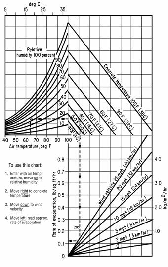
Figure 1 ACI 308-81
511.11 Slipform Construction of Bridge Railing. If Class HP concrete is
specified, the Contractor may replace up to two-thirds of the No. 8 size
coarse aggregate with No. 57 size coarse aggregate. The Engineer will submit the approved slipform concrete mix
design to the Laboratory for record purposes.
If slipforming, provide finished concrete
conforming to the following tolerances from plan dimensions:
|
Reinforcing steel cover |
-1/2 inch, +1/2 inch (-13 mm, +13 mm) |
|
Top width dimension |
-0, +1/4 inch (+6 mm) |
|
Bottom width dimension |
-0, +1/2 inch (+13 mm) |
|
Surface flatness |
1/4 inch in 10 feet (6 mm in 3 m) |
|
Vertical alignment (Deviation from a line parallel to the
grade line) |
1/2 inch in 20 feet (13 mm in 6 m) |
Tie all joints and splices in bridge railing reinforcing steel. Before placing concrete, perform a slipforming dry run to verify reinforcing clearance and rigidity of the reinforcing cages. Adjust and stabilize the cage as necessary to establish the required clearances and to ensure the cage will not move during slipforming. The Contractor may add any additional diagonal reinforcing steel between the front and rear vertical reinforcing faces to establish the required rigidity.
Repair or patch honeycombing, cracking, tearing, and other defects immediately after concrete exits the slipform equipment. Completely fill defects with concrete without using water to smooth or close the surface.
After the concrete initially sets, but before any shrinkage cracks develop, saw control joints 1 1/4 inches (32 mm) deep into the perimeter of the parapet. Generally, initial set is within 6 hours of batching of the concrete. Ensure that all joints are sawed within 24 hours of placement. Saw control joints using an edge guide, fence, or jig to ensure that the joint is straight, true, and aligned on all faces of the parapet. The joint width shall be the width of the saw blade, a nominal 1/4 inch (6 mm). Caulk the control joints with a polyurethane or polymeric material conforming to ASTM C 920, Type S.
Slip formed concrete requires different slumps than those listed in Item 499 or other plan specified concrete. Provide a slump such that the concrete exiting the slipform does not pull but is stiff enough to prevent waviness and sags in the finished surfaces. Cure slipform concrete according 511.17, Method A. Because slipformed concrete has a low water-cement ratio, timely application of the water cure is critical in helping control shrinkage cracks.
Furnish platforms as necessary to protect traffic passing under the bridge from falling debris during the slipforming operation, to allow access for completing the finishing operation, and to allow the Engineer access to the outside of the parapet.
The Engineer will inspect the slipformed surface for horizontal cracking no earlier than 21 days after completion of the slipforming operation. Repair all horizontal cracks by epoxy injection. If a concrete sealer was applied, repair damage to the sealer after completing the epoxy injection.
511.12 Construction Joints. If construction joints are shown on the plans, place all concrete between consecutive joints in a continuous operation. Do not place concrete against a joint for at least 12 hours, or as required by 511.17.
Obtain the Director’s approval before placing any construction joint not shown on the plans or required by 511.10.
Before placing concrete, determine the location where the day’s concrete placing ends. If practical, end placing the day’s concrete perpendicular to the lines of principal stress and in regions of small shear. Do not install horizontal joints in concrete girders and beams.
Form construction joints using bulkheads with keyways. Locate keyways clear of exposed surfaces by approximately one-third the thickness of the joint.
Where practical, avoid horizontal joints in piers, abutments, and retaining walls, otherwise locate horizontal joints 2 feet (0.6 m) or more above the normal water level.
For construction joints not shown on the plans and above ordinary low water, in abutments, and in retaining walls that retain earth fills, install a 36-inch (1 m) strip of Type B waterproofing according to Item 512 to the back of the joint.
Avoid joints in cantilevered members.
Dampen the surface of the concrete of the horizontal construction joints immediately before placing adjoining concrete.
Place and protect horizontal construction joints between bridge slabs and superimposed curbs, parapets, sidewalks, and median strips in the same manner as the remainder of the slab. Cure the construction joints according to 511.17.
Avoid disturbing the bond between protruding reinforcing steel and the deck concrete. If using the curb areas to place the deck, tie and brace the reinforcing steel to prevent its movement.
Where walls or columns support slabs or beams, place concrete in wall or column to the bottom of the slab or beam and allow the concrete to settle for at least 2 hours before placing concrete in the slab or beam.
511.13 Work Stoppage. If the work is unexpectedly interrupted by breakdowns, storms, or other causes, rearrange the freshly deposited concrete to provide a suitable construction joint. If this joint occurs at a section with shear stress, prevent a plane of weakness by providing an adequate mechanical bond across the joint by forming a keyway, inserting reinforcing steel, or by some other means satisfactory to the Engineer.
511.14 Depositing Concrete Under Water. Except for cofferdam seals and drilled shafts, do not place concrete under water.
511.15 Depositing and Curing Concrete During Cold Weather. If placing concrete when the atmospheric temperature is 32 °F (0 °C) or less, or if weather forecasts predict these temperatures during the curing period, follow the procedures of this subsection.
Heat the water or aggregate, or both, as necessary to produce concrete with a temperature when placed of at least 50 °F (10 °C) but not greater than 70 °F (21 °C).
Place concrete against materials with a temperature of greater than 32 °F (0 °C). If necessary, heat the forms, reinforcing steel, and foundation materials before placing the concrete.
Maintain the concrete surface temperature between 50 and 100 °F (10 and 38 °C) for a period of not less than 5 days, except as modified in 511.15.C. After the minimum cure period of 5 days, reduce the concrete surface temperature at a rate not to exceed 20 °F (11 °C) in 24 hours until the concrete surface temperature is within 20 °F (11 °C) of atmospheric temperature.
Install sufficient high-low thermometers to readily determine the concrete surface temperature. For deck slabs, install high-low thermometers to measure deck bottom surfaces, deck fascia surfaces, and deck top surfaces.
Maintain the concrete curing temperature using a heated enclosure, insulated forms, or by flooding, except cure deck slabs less than 10 inches (250 mm) thick using more than just insulated forms.
Remove falsework and open cold weather concrete to traffic according to 511.17.
A. Heated Enclosure. Construct the heated enclosure to surround the top, sides, and bottom of the concrete. Construct strong and wind proof enclosures that contain adequate space to allow free circulation of air around the forms and concrete.
Before placing concrete, construct the enclosure and heating devices to the extent allowed by the concrete operation. As the concreting operation progresses and as soon as possible after placing concrete, complete construction of the enclosures and apply heat. Supply heat by a method that continuously maintains a reasonably uniform temperature throughout the enclosures and does not discolor the concrete.
Vent combustion-type heating devices outside the enclosure.
If dry heat, other than free steam, maintains the enclosure temperature, immediately cover exposed concrete with two thicknesses of burlap. Continuously wet the burlap and, except for required rubbing of the concrete, do not remove the burlap during the heating period.
If wood forms without liners are left in place more than 2 days after the placing of concrete, thoroughly wet the forms at least once each day for the remainder of the heating period. If forms are removed during the heating period, thoroughly drench the concrete with water and, for the remainder of the heating period, cover and wet the concrete with burlap as specified above.
B. Insulation. Install sufficient thermometers to readily determine the concrete surface temperature. If the surface temperature approaches 100 °F (38 °C), loosen or otherwise vent the forms or insulation to keep the surface temperature within the limits specified above. If insulation does not maintain the minimum required temperature, promptly enclose the concrete as specified in 511.15.A or flood the concrete as specified in 511.15.C.
Use a wind and water resistant insulating material. Ensure edges, corners, and other points of extreme exposure are adequately insulated. Place a tarpaulin or other Engineer approved waterproof cover over the insulation to protect the concrete top surface.
C. Flooding with Water. The Contractor may flood the concrete with water provided flooding does not damage the concrete. Heat the water to a temperature from 50 to 100 °F (10 to 38 °C). The Contractor may stop using heated water after 48 hours if the concrete remains flooded to a depth of 1 foot (0.3 m) above its highest elevation for at least the next 120 hours.
511.16 Removal of Forms. To facilitate finishing, remove forms from vertical surfaces that receive a rubbed surface finish as soon as the concrete has hardened sufficiently that rubbing will not damage it.
511.17 Curing and Loading. Remove falsework and open structures to traffic after the concrete has cured for the time specified by Table 511.17-1.
|
Table 511.17-1 |
|||
|
|
Span[1] |
Age of Concrete in Days |
|
|
No Beam Test |
Beam Test [2] |
||
|
Removing Falsework |
Over 10 feet (3 m) |
14 |
5 |
|
10 feet (3 m) or less and all pier caps |
7 |
3 |
|
|
Traffic [3] |
Any |
14 |
7 |
|
[1] Span is defined as the horizontal distance between faces of the supporting elements when measured parallel to the primary reinforcement. |
|||
|
[2] Applicable only when the average modulus of rupture for two tests is not less than 650 psi (4.5 MPa). |
|||
|
[3] When placing Class HP concrete for a superstructure between October 15 and March 15, open the deck to traffic no sooner than 30 days after placement. |
|||
If the air temperature surrounding the concrete is maintained between 32 and 50 °F (0 and 10 °C), and if the provisions of 511.15 do not apply, maintain the concrete above 32 °F (0 °C) for 7 days or until a successful beam test, except this time shall not be less than 5 days.
If a beam test is not performed, maintain the air temperature surrounding the concrete above 50 °F (10 °C) for 7 days. Extend the 7-day period and the times for removing falsework and opening to traffic one hour for each hour the temperature of the air surrounding the concrete is below 50 °F (10 °C) and until the concrete has experienced 7 days, or 168 hours, of temperature above 50 °F (10 °C). Cure concrete as follows:
|
Location |
Curing Method [1] |
|
Superstructure concrete |
Method A |
|
Concrete to which sealer is applied |
Method A |
|
Construction joints |
Method A |
|
Top surface of Class HP concrete deck superstructure concrete |
Method A followed by Method B |
|
Concrete with waterproofing |
Method A or Method B |
|
All other concrete |
Method A or Method B |
|
[1] Method A is water curing. Method B is membrane curing. If using Method B on areas to be waterproofed, remove the curing membrane. |
|
Do not install compression rings on pier columns or similar items of construction for supporting falsework or subsequent construction until after a 72-hour curing period.
Do not apply loads to or perform work on new concrete until workers and materials will not damage the concrete or interfere with its curing. Allow at least 36 hours or until the average of two beam tests is greater than 650 pounds per square inch (4.5 MPa) before working on new concrete, but do not interfere with curing of new concrete.
Concrete curing methods are as follows:
A. Method A, Water Curing. With the exception of the top surface of deck superstructure concrete, protect surfaces not covered by forms immediately after final finishing with two thicknesses of wet burlap. Keep burlap wet for at least 7 days by the continuous application of water. If forms are removed before 7 days, immediately drench the exposed concrete with water and cover it with burlap. Continuously apply water to the burlap for the remainder of the curing period.
Instead of continuous application of water, with the exception of the top surface of deck superstructure concrete, the Contractor may cover the wet burlap with white polyethylene sheeting or plastic coated burlap blankets conforming to 705.06. Place plastic coated burlap blankets wet and with the burlap side against the previous layer of wet burlap. Sufficiently lap and secure adjoining plastic coated blankets or polyethylene sheets at the laps and edges to form a seal that maintains the concrete wet at laps and edges. Cover white polyethylene sheeting or plastic coated blankets containing holes or tears with an additional covering of plastic sheeting or blankets as directed by the Engineer.
Cover the top surface of deck superstructure concrete with a single layer of clean wet burlap after it is bullfloated if necessary, and finished. Keep the burlap wet by a continuous flow of water through soaker hoses and cover the hoses with a 4 mils (100 mm) white opaque polyethylene film for 7 days. After 7 days, allow the surface of the deck to dry.
After curing the top surface of Class HP deck superstructure concrete for 7 days, remove the burlap and standing water. Within 12 hours after removing the burlap, apply a curing membrane and cure the concrete according to Method B.
B. Method B, Membrane Curing. Immediately after the free water has disappeared on surfaces not protected by forms, apply curing material conforming to 705.07, Type 1 or 1D. If forms are removed before the end of the 7-day curing period, apply curing material on the concrete exposed by removing the forms.
Thoroughly agitate curing material immediately before use. Apply the membrane curing material at the rate of at least 1 gallon per 200 square feet (1 L/5 m2) of surface and in a fine mist to provide a continuous, uniform, and water impermeable film without marring the concrete surface. If the film is broken or damaged during the specified curing period, apply curing material as specified above to the damaged or affected areas.
Do not allow workers, materials, and equipment on the concrete during the curing period, unless adequately protecting the membrane curing material from damage.
511.18 Surface Finish. Immediately after removing forms, clean, dampen, and fill with mortar all cavities produced by form ties, honeycomb spots, broken corners or edges, and other defects. Use a mortar of the same proportions used in the concrete being finished. Substitute sufficient white cement for the regular cement in the mortar used to fill holes and perform other corrective work to produce finished patches of the same color as the surrounding concrete. Finish other contiguous exposed surfaces on the structure in a similar manner and to the extent required to produce a uniform appearance.
On all exposed surfaces, remove fins and irregular projections with a stone or power grinder, taking care to avoid contrasting surface textures.
A. Grout Cleaning. If grout cleaning is shown on the plans or necessary for corrective work, wet the concrete surface and then uniformly cover the concrete with a grout consisting of one part cement, 1 1/2 parts fine sand conforming to 703.03, and sufficient water to produce a mortar with the consistency of thick paint. In the quantity determined by the Engineer necessary to match the color of the concrete, use white portland cement in the grout. uniformly apply the grout with brushes or spray guns, completely filling air bubbles and holes. Immediately after applying the grout, vigorously scour the concrete surface with a cork or other suitable float. While the grout is still in a plastic condition and while the grout does not pull from the holes or depressions, finish the surface with a sponge rubber or other suitable float, removing excess grout. After the grout thoroughly dries, vigorously rub the surface with a dry burlap, removing dried grout until there is no visible film of grout remaining on the surface. Perform the entire cleaning operation of each area on the same day. Remove dark spots or streaks that remain after the cleaning operation using a fine grained silicon carbide stone. Stop rubbing with the silicon carbide stone before the surface texture changes. Unless otherwise directed by the Engineer, perform grout cleaning during the final project clean up.
B. Rubbed Finish. If a rubbed finish is shown on the plans, if possible, remove forms within 2 days after placing concrete. Finish the surface as specified above to correct defects. After the mortar used for finishing is thoroughly set, and for a minimum of 2 hours before starting the rubbed finish, thoroughly saturate the concrete with water.
Rub surfaces to be finished with a medium coarse silicon carbide stone until all form marks, projections, and irregularities are removed, all voids are filled, and a uniform surface is obtained. Leave the paste produced by rubbing in place. Other than water, do not apply additional material to the surface. After placing concrete above the finishing area, obtain the final finish by rubbing the concrete with a fine silicon carbide stone and water until the entire surface is of a smooth texture and uniform in color. Protect surfaces with a rubbed finish from damage caused by subsequent construction operations. If damaged, clean and refinish the surface as specified above.
511.19 Roadway Finish. Finish and test concrete deck slabs according to 451.12. Do not groove or broom finish a strip of surface 9 to 12 inches (220 to 300 mm) wide adjacent to curbs and barriers. Provide a broom drag finish on concrete deck slabs in the longitudinal or transverse direction.
The Engineer will approve the finishing machine. Provide a self-propelled machine with forward and reverse drive mechanisms that enable precise control of machine velocity in both directions. The machine shall have two rotating rollers, leveling augers, and either a vibrating pan or vibrating rollers. Field verify that the vibrating frequency of the pans or rollers are from 1500 to 5000 pulses per minute. Do not use vibrating rollers that have fins protruding more then 1/4 inch (6 mm) from the roller. Use a finishing machine capable of finishing transversely while traveling in both directions across the deck. Provide screeds capable of rising above the concrete surface. Provide a finishing machine capable of finishing the full width of the decks between curbs or parapet walls. The wheels of the finishing machine shall run on temporary riding rails adequately supported on the structural steel or falsework of the deck. Make the rail and rail supports of steel and arrange the rail and rail supports so that the weight of the finishing machine and the operator cause zero vertical deflection while traveling across the deck. Ensure the rail is straight, with no sections exceeding a tolerance of 1/8 inch in 10 feet (3 mm in 3 m) in any direction. Elevate support rails a sufficient distance above the slab to allow the simultaneous hand finishing of areas not machine finished. Fabricate and install rail supports to allow removal to at least 2 inches (50 mm) below the top of the slab. Fill holes formed by the removal of rail supports during the final finishing of the slab.
For structures with a
skew angle greater than fifteen (15) degrees and up to fifty (50) degrees,
place the finishing machine within 5°of the skew angle of the structure. For structures with a skew angle greater than
fifty (50) degrees, place the finishing machine at fifty (50) degrees.
511.20 Bridge Deck Grooving. After Class S concrete has cured, saw transverse grooves into the deck.
After water curing Class HP concrete and either before applying curing compound or some period after applying curing compound and before opening the bridge to traffic, saw transverse grooves into the deck. If sawing grooves after applying the curing compound, and concrete deck is less than 30 days old, reapply the curing compound after removing standing water, within 12 hours after sawing grooves in the deck.
The grooving of both Class S concrete and Class HP concrete shall be performed as specified below.
Use diamond blades mounted on a multi blade arbor on a self-propelled machine that was built for grooving of concrete surfaces. The groove machine shall have a depth control device that detects variations in the pavement surface and adjusts the cutting head height to maintain the specified depth of the groove. The grooving machine shall have devices to control alignment. Do not use flailing or impact type grooving equipment.
Begin and end grooves 9 to 12 inches (220 to 300 mm) from curbs, parapet toes, or deck edges, and saw grooves perpendicular to the bridge centerline.
Provide an experienced technician to supervise the location, alignment, layout, dimension, and grooving of the surface.
Saw grooves in a continuous pattern across the surface. Stop sawing 9 to 12 inches (220 to 300 mm) from any device in place in a bridge deck, such as scuppers or expansion joints. Stop sawing 2 inches to 2 feet from skewed expansion joints. Saw grooves in a random pattern spaced at 3/8 to 1 3/4 inch (10 to 45 mm), with 50 percent of spacings less than 1 inch (25 mm). Saw grooves approximately 0.15 inches (4 mm) deep and 0.10 inches (3 mm) wide.
At the beginning of each work shift, furnish a full complement of grooving blades with each saw that are capable of cutting grooves of the specified width, depth, and spacing.
If during the work, a single grooving blade on a machine becomes incapable of cutting a groove, continue work for the remainder of the work shift. The Contractor is not required to cut the groove omitted because of the failed blade. Should two or more grooving blades on a machine become incapable of cutting grooves, cease operating the machine until it is repaired.
Continuously remove all slurry and remaining residue from the grooving operation and leave the deck surface in a clean condition. Prevent residue from grooving operations from flowing across shoulders or across lanes occupied by public traffic or from flowing into gutters or other drainage facilities. Remove solid residue before the residue is blown by passing traffic or by wind.
Provide water as necessary to saw grooves according to this subsection.
511.21 Sidewalk Finish. After placing, strike off the concrete with a template and finish the concrete with a float to produce a sandy texture.
511.22 Sealing Joints and Cracks. After completing all curing operations and allowing the deck to thoroughly dry, seal the following areas with a high molecular weight methacrylate (HMWM) sealer as specified in Item 512 before opening the deck to traffic:
A. Transverse joints in the deck.
B. Joints between the concrete deck and steel end dams.
C. Longitudinal joints in the deck.
D. Longitudinal joints between the deck and safety curb, barriers, and parapets, etc.
E. Cracks discovered in the deck that will be checked on the top and bottom surface before opening the deck to traffic.
511.23 Class HP Concrete Testing. If included as a separate pay item, perform the following tests on the concrete.
A. Rapid Chloride Permeability Tests. Perform test according to AASHTO T 277. Take a minimum of three tests for decks containing less than 100 cubic yards (75 m3) of superstructure concrete. For all other decks, take six tests. Test deck superstructure concrete samples obtained from the actual concrete used.
Provide the Engineer with results of rapid chloride permeability tests at 28, 56, and 90 days.
B. Drying Shrinkage Tests. Perform test according to ASTM C 157 and at the frequency specified for rapid chloride permeability tests.
Provide the Engineer with results of drying shrinkage tests at 4, 7, 14, 28, 56, and 90 days.
C. Heat of Hydration Testing. Perform testing to determine the potential for length change due to thermal expansion and contraction. Immediately after placing the deck, install three thermometers into the fresh concrete at a location that is accessible for readings and representative of the overall deck pour. Locate the thermometer bulbs at 1 inch (25 mm) below the surface of the concrete, at approximately mid-slab, and at 1 inch (25 mm) above the bottom deck form. Leave the thermometers in place throughout the testing time. The Contractor may lubricate and place the thermometers in a thin plastic sheath to facilitate eventual removal.
Record temperatures at the following intervals:
|
Test Intervals |
Time |
|
2 hours |
first 12 hours |
|
3 hours |
second 12 hours |
|
4 hours |
second day |
|
8 hours |
third thru fifth day |
Record ambient air temperatures when taking concrete temperatures. Ensure that all testing is performed by a testing laboratory regularly inspected by the Cement and Concrete Reference Laboratories (CCRL). Furnish a copy of the last CCRL inspection report to the Engineer before the test slab pour.
If the Contractor uses Class HP 1 or 2 for parapets or substructures, perform three additional chloride permeability and drying shrinkage tests for the parapets or substructure concrete. If used for parapets, perform a heat of hydration test as described above with one thermometer located at 1 inch (25 mm) below the top of the parapet and a second thermometer located 19 inches (500 mm) below the top of the parapet, approximately midway between the front and back faces of the parapet. The Engineer will not require additional testing for units constructed with the same concrete mix option as the deck.
Tabulate test results on the attached form and forward the form to the Laboratory no later than 10 days following the completion of the tests.
After removing thermometers, drill out and fill the holes as approved by the Engineer.
511.24 Method of Measurement. The Department will measure the appropriate concrete item by the number of cubic yards (cubic meters) determined by calculations from plan dimensions, in place, completed and accepted.
The Department will make deductions for portions of primary structural members embedded in concrete. The Department will not make deductions for the volume of reinforcing steel, conduits or embedded piles.
Superstructure concrete includes the concrete in deflective parapets not having a metallic railing.
The Department may measure deck concrete by either volume or area using plan dimensions.
511.25 Basis of Payment. The Department will not pay for Class HP concrete Testing until the Laboratory receives all test results.
The Department will not pay for additional test slabs resulting from proportioning or batching sequence modifications for the Class HP.
If the contractor elects to use high early strength concrete, the Department will not pay additional costs associated with the use of these materials even if use is desirable to expedite the work.
The Department will not pay for additional reinforcing steel required to adequately stabilize the cages.
The Department will not pay for repairs to horizontal cracks by epoxy injection or, if a concrete sealer was applied, for repairs to the sealer after the completing the epoxy injection.
The Department will not pay extra for any type of surface finish specified in 511.18, the cost being considered as included in the price bid for concrete.
If the Contractor elects to saw the deck after applying the curing compound, the Department will not pay to reapply the curing compound.
All costs for sealing as specified in 511.22 is incidental to the appropriate concrete item. The Department will not make separate payment for sealing.
The Department will pay for accepted quantities at the contract prices as follows:
Item unit Description
511 Cubic
Yard Class ___
Concrete, ___
(Cubic Meter)
511 Cubic
Yard Class S Concrete,
Bridge Deck
(Cubic Meter)
Square Yard
(Square Meter)
511 Cubic
Yard Class HP,
(Cubic Meter)
511 Square
Yard Class HP,
(Square Meter)
511 Cubic
Yard Class HP,
(Cubic Meter)
511 Cubic
Yard Class HP,
Concrete Substructure
(Cubic Meter)
511 Lump Sum Class HP Concrete Test Slab
511 Lump Sum Class HP Concrete Testing
ITEM 512 TREATING CONCRETE
512.01 Description
512.02 Materials
512.03 Sealing of Concrete Surfaces
512.04
512.05 Soluble Reactive Silicate (SRS) Concrete Treatment
512.06
Treating
512.07 Sealing Cracks by Epoxy Injection
512.08 Waterproofing
512.09 Method of Measurement
512.10 Basis of Payment
512.01 Description. This work consists of sealing and treating concrete surfaces, sealing cracks in concrete, and applying waterproofing to structures.
512.02 Materials. Furnish materials conforming to:
Asphalt cement.................................. 702.01 (PG 64 - 22)
Asphalt primer for................. 702.02 (RC-70 or RC-250),
.... waterproofing..................................................... 702.05
HMWM Resin........................................................ 705.15
Epoxy-Urethane Sealer......................................... 705.23.1
Non-epoxy Sealer................................................. 705.23.2
Soluble Reactive Silicate(SRS)................................. 705.24
Gravity Fed Resin................................................... 705.25
Epoxy injection Materials....................................... 705.26
.... Sand........................ 703
with the following exceptions:
.... Maximum moisture content of 0.5 of the percent of absorption when treated according to California Test 226.
Grading:
|
SIEVE SIZE |
% PASSING MAX. |
|
No. 4 (4.5mm) |
100 |
|
No. 8 (2.36mm) |
90 - 100 |
|
No. 20 (850µm) |
5 -15 |
|
No. 50 (300µm) |
0 - 5 |
Emulsified asphalt primer,................ 702.04 (MS-2, SS-1)
Asphalt for waterproofing...................................... 702.06
Hot applied joint sealer........................................... 705.04
Type 3 membrane primer........................................ 705.04
Waterproofing fabric............................................... 711.24
Sheet Type 2 membrane waterproofing.................. 711.25
Sheet Type 3 membrane waterproofing.................. 711.29
512.03 Sealing
of Concrete Surfaces. This work consists of applying
an approved sealer on existing and new
concrete surface areas after the concrete is cured and repairs completed and
cured. Apply the sealer to locations described in the plans. Apply the sealer
listed in the pay item description. Choose a type of sealer if no sealer is
listed in the pay item description.
A.
Equipment. Use application equipment recommended by the sealer manufacturer. Use
spray equipment, tanks, hoses, brooms, rollers, coaters, squeegees, etc., that
are clean, free of foreign matter, oil residue and water.
B.
Mixing. Mix the sealer
according to the manufacturer's recommended procedures. Furnish the Engineer with
the manufacturer’s application instructions. Do not mix or apply the sealer
until the manufacturer’s written recommendations are supplied to the Engineer.
Mix and maintain materials at a uniform consistency during application.
C.
Storage. Store all
sealer components in tightly sealed containers, in a dry location, and as
recommended by the manufacturer. Deliver unopened drums or containers of the
sealer or sealer components to the job site with the manufacturer's numbered
seal intact.
D. Application
submittals. At least five (5) days before sealing, provide
the Engineer the
sealer manufacturer’s written requirements for application equipment, mixing
equipment, mixing procedures, mixing time, storage requirements, recoat times
and temperatures, and MSDS sheets.
E. Surface
Condition. Only apply sealers to
surfaces which are dry, free from dust, dirt, oil, wax, curing compounds,
efflorescence, laitance, coatings and other foreign materials. Visually inspect
all surfaces before applying sealer.
Repair any structurally unsound surfaces, weak sections or spalled areas
before applying any sealer. Cure repaired areas for at least seven (7)
days.
Air dry all concrete surfaces
for at least ten (10) days after completion of required curing..
For accelerated cure
of precast concrete, obtain the required 28 day strength and air dry the
surfaces at least ten (10) days after completing accelerated cure. Follow the requirements of the above
paragraphs for any repaired areas on the precast concrete.
F. Surface Preparation. Remove dust,
dirt, oil, wax, curing compounds, efflorescence, laitance, coatings and other
foreign materials from surfaces to be sealed.
Use one or
both of the following methods to produce a surface that feels and looks like
100 grit sandpaper or coarser. Provide
the Engineer sandpaper for comparison
1. Water blast at 7,000 psi (48 MPa) minimum, or
2. Abrasive blast, followed by air brooming or
power sweeping, to remove dust and sand from the surface and opened pores.
Install
suitable traps, filters, drip pans and other separation devices in the cleaning
equipment so oil and other foreign material are not deposited on the surface.
If the
concrete surface had curing compound applied, acid test the surface after
blasting to see if the curing compound was removed. Perform the acid test for every 500 square ft
(47 square meters). Use a solution of 1
part 20º baume muriatic acid and 2 parts water.
Apply 4 to 5 drops to the concrete surface. If foaming/fizzing occurs the curing compound
is removed. Rinse the tested location
with an ammonia solution to neutralize the concrete area tested (1 cup ammonia
to 5 gallons water).
[NOTE: Muriatic acid and ammonia can be bought in a
hardware store. Muriatic acid is used to
clean masonry. Only dilute by pouring
the acid into the water. DO NOT pour the
water into the acid.]
When
surfaces show intermittent or no foaming, use chemicals or other cleaning
compounds to remove the curing compounds.
Only use products approved by the sealer manufacturer. Furnish the
Engineer documentation of the sealer manufacturer’s
approval and method to test if materials are removed.
After
re-cleaning perform the acid test to confirm removal of the curing compound..
G. Application
and Coverage. Apply the sealer
between twelve (12) hours and 48 hours after surface preparation. Do not apply sealer if rain is anticipated
within six (6) hours after application. Clearly mark where the sealer application
stops if not continuous.
1. Epoxy
- Urethane sealers.
a. Apply the epoxy coat of the epoxy-urethane
sealer at the coverage rate of 120 square feet per gallon (2.9 square meter per
liter). Use a coverage rate of 150
square feet per gallon (3.6 square meter per liter) when the Laboratory’s
qualified products list for the epoxy authorizes it. Apply the Urethane coat of the epoxy-urethane
sealer at a rate of 200 square feet per gallon (4.8 square meter per liter).
When surfaces are not smooth and flat, adjust the coverage rates by the
following formulas to determine the correct coverage rate.
(1) For
surfaces using large stone liners and standard concrete = specified coverage
rate (sq ft/gal [sq m/l]) x 0.8
(2) For
surfaces using large stone liners and porous concrete = specified coverage rate
(sq ft/gal [sq m/l]) x 0.7
(3) For
surfaces using fluted liners and standard concrete = specified coverage rate
(sq ft/gal [sq m/l]) x 0.5
b. Only apply sealer when the surface temperature
is 50 °F (10 °C) or above
c. Apply with a brush, squeegee, roller or
spraying equipment and as recommended by the manufacturer.
d. Apply one coat of epoxy and one coat of the
urethane top coat. Time between coats shall meet the manufacturer's written
recommendation provided to the Engineer during
512.03.D. Use epoxy and urethane from the same manufacturer. Achieve specified
coverage regardless of the number of passes per coat.
e. Tint so the final color is Federal Color
Standard No. 17778 - Light Neutral. Pigment content shall be limited so
as not to reduce sealing effectiveness of the second coat. Refer to the plans
for colors for specific projects.
f. Sags and runs are not acceptable in the
sealer.
g. For sealed sidewalks or other horizontal
surfaces with repetitive foot traffic or vehicular traffic, integrate 1-1/2
lbs. per square yard (0.8 kg/m2) of silica sand into the surface of the second
coat to produce a non-skid surface satisfactory to the Engineer.
2. Non-epoxy
sealer.
a. Apply the sealer according to the
manufacturer's recommended mode of application and under the observation of the
Engineer.
b. Coverage.
I. Surfaces subject to abrasive wear (bridge
decks, bridge deck shoulders and sidewalks); Minimum, one gallon (3.875 liter)
of sealer for each 100 square feet (9.0 square meter);
II. Curbs, vertical surfaces of beams and deck
slabs subject to direct roadway drainage; Minimum, one gallon (3.875 liter) for
each 125 square feet (11.5 square meter)
III. Other surfaces (for example, parapets,
abutments, pier caps and median dividers); Minimum, one gallon (3.875 liter) for
each 150 square feet (14.0 square meter)
Stone or
flutted formed concrete surfaces may require additional sealer materials for
coverage.
c. Apply sealer on horizontal surfaces in a
one-pass operation at the required coverage. An acceptable application
procedure consists of saturating the surface and waiting a few seconds for the
sealer to completely penetrate the concrete surface. Broom in the sealer if
recommended by the manufacturer.
d. Apply sealer on vertical surfaces to saturate
the surface. The surface is saturated
when runs of 6 to 12 inches develop. Apply additional passes in 10 to 15 minute
intervals until the coverage rate is achieved. Apply sealers with brush or
roller if recommended by the manufacturer.
e. After 10 to 15 minutes, squeegee off excess
material on smooth finished or dense concretes where the required coverage is
not absorbed.
f. For sealed sidewalks or other
horizontal surfaces with repetitive foot traffic or vehicular traffic,
integrate 1-1/2 lbs. per square yard (0.8 kg/m2) of silica sand into the sealer
application to produce a non-skid surface satisfactory to the Engineer.
g. Tint clear non-epoxy sealers with a vanishing
dye that will not damage the concrete.
h. Do not apply sealer if the ambient temperature
is below 40 °F (5 °C) or will fall below 32 °F (0 °C) within 12 hours after application.
H.
Test Site/Application.
Apply epoxy-urethane or non-epoxy sealer to measured coverage areas, both on
horizontal and vertical surfaces, and on different concrete types,
demonstrating:
1. The project’s visual effects for the
epoxy-urethane sealer application at the required coverage rate.
2. Visually, the absorption necessary to achieve
the specified coverage rate for the non-epoxy sealer. Use at least ½ gallon (2
liter) of sealer, following the manufacturer's recommended method of
application, for the total of the test surfaces.
3. Apply to the deck, safety curb or sidewalk for
the horizontal test surfaces and use an abutment parapet or pier face for the
vertical test surface so different textures are tested.
I. Appearance. Epoxy/Urethane sealers. uniform
appearance and the final color shall visually match the test section. Re-coating, removal and re-application or
other methods recommended by the manufacturer will be required to correct final
appearance. Non Epoxy Sealers. The
sealer shall result in a uniform appearance.
J. Traffic. Allow traffic on deck shoulder areas after 12 hours of drying time for
an epoxy/urethane sealer. Keep traffic off a non-epoxy sealer until the sealer
is dry.
K. Safety Precautions. Follow precautions
defined on the manufacturer's MSDS. Provide the Engineer a copy
of the MSDS sheet for information before any work commences.
L. Protection
of Adjoining Surfaces and the Public. Protect the public during all operations, especially when applying
sealer to the fascia or the underside portions of a bridge that spans an area
used by the public.
During
sealing, mask off, or use other means of protection, for surfaces not being
sealed. Protect asphalt and mastic type surfaces from spillage and heavy overspray.
Do not apply sealers to joint sealants which have not cured according to the
manufacturer's instructions. Joint sealants, traffic paints and asphalt overlays
may be applied to the treated surfaces 48 hours after the sealer has been
applied. Protect nearby steel, aluminum or glass surfaces when non-epoxy overspray
could be deposited on those surfaces.
M. Environmental
Requirements. Protect plants and vegetation from overspray
by covering with drop cloths.
512.04
A. Limitations. Do not perform this work during the period
beginning November 1st and ending March 31st.
B. Surface Preparation. Remove roadway dirt and debris from the area of the
deck to be treated. Sweep, sandblast, then with the use of a manual or power
broom sweep and blow with compressed air so that the surfaces to which the
sealer is to be applied is dry and free of dust and dirt. Use high pressure compressed
air to blow all loose material from visible cracks. Fit the cleaning equipment
with suitable traps, filters, drip pans, driers and other devices to prevent
oil and other foreign material from being deposited on the surface. Do not
allow traffic on the clean surface prior to application of the sealer. Remove
existing pavement markings according to Section 641.10 of the Specifications. Remove all traces of asphalt or petroleum
products and concrete curing seals by abrasive blasting prior to air sweeping.
C. Installation. Provide a compatible promoter/initiator
system capable of providing the same physical qualities of the hardened resin
as if promoted/initiated with 2% cobalt naphthanate (6%) and 2% cumene
hydroperoxide. Store materials at 65-80 ºF (18-27 ºC). Provide a system that
has a resin gel time of not less than 40 minutes to not more than 1½ hours at
the time and temperature of application.
Adjust the
gel time to compensate for the change in temperature throughout the day. The
temperature of the surfaces to be treated may range from 50 ºF (10 ºC) to 120 ºF
(49 ºC). Arrange to have a technical representative on site to provide mixing
proportions equipment suitability, and safety advice. Any conflict between
these provisions and representative's advice shall be resolved at the job site.
The technical representative shall remain at the job site until such time as he
and the Engineer agree
that the Contractor is
qualified in all aspects of the application of the sealer.
Do not
allow the promoter and initiator, if supplied separate from the resin, to
contact each other directly. Do not store containers of promoter or initiators
together in a manner that will allow leakage or spillage from one to contact
the containers or materials of the other.
Machine
application of the resin may be performed by using a two-part resin system
utilizing a promoted resin for one part and an initiated resin for the other
part. This two-part resin system may be combined at a spray bar through
positive displacement atomization of the resin. Do not use compressed air to
produce the spray.
Use
appropriate cleaning and flushing of equipment, tools, etc., with an appropriate
solvent, as approved by the Engineer, in such a manner to minimize personal and
environmental hazards. Advise workman that the resin will soften gum rubber
soles, and a face-mask should be used to protect from accidental splashes.
Clothing and leather saturated with resin will harden and become useless.
Prior to
resin application the surface to be treated shall be visibly dry and its
temperature between 50º F (10º C) and 120º F (49º C). Do not apply the resin
within 24 hours after a rain or when rain is forecast within 12 hours or when
the ambient air temperature is below 50º F (10º C). Pre-mark the deck to
control mixed material usage and to provide a rate of application of
approximately 100 square feet per gallon (2.45m2/L). The exact rate
shall be determined by the Engineer prior
to commencing full-scale deck treatment operations.
Before
using the material submit to the Director copies of the manufacturer certified
test data showing that the material complies with the requirements of this specification.
The test data shall be developed by an independent approved testing laboratory,
and shall include the brand name of the material, name of manufacturer, number
of the lot tested and date of manufacture. When the material has been approved
by the Director, further testing by the manufacturer will not be required unless
the formulation of manufacturing process has been changed, in which case new
certified test results will be required. The manufacturer shall certify that
the formulation is the same as that for which data has been submitted. The
state reserves the right to sample and test delivered lots for compliance.
Flood the
deck surfaces resin, allowing penetration into the concrete and filling of all
cracks. Limit the initiated mix of promoted resin to 5 gallons (19L) at a time for manual
application. A significant increase in viscosity shall be cause for rejection.
Apply the treatment within 5 minutes after complete mixing. Redistribute excess
material by squeegee or brooms within 10 minutes after application.
Take all
steps necessary to prevent the resin from flowing into lanes open to traffic.
Broadcast sand over the entire treated area of the bridge deck by mechanical
means to affect a uniform coverage of 0.80 to 1.2 pounds per square yard (0.43
kg/m2 to 0.65 kg/m2). The sand shall be uniformly graded
aggregate conforming to the quality requirements of 703 and shall conform to
the following limits for grading:
|
Sieve Size |
% Passing Max. |
|
No. 4 (4.75mm) |
100 |
|
No. 8 (2.36mm) |
90-100 |
|
No. 20 (850µm) |
5-15 |
|
No. 50 (300µm) |
0-5 |
It is the
intention of the specification to allow the use of commercially available blast
sands applied by a common lawn broadcast type seeder/spreader. Place sand
between 10 to 15 minutes behind the resin spreading front and before any
jelling of the resin occurs. If the surface contains large deep cracks, the
low-viscosity liquid could run completely through the concrete slab. Apply a
second coat in these areas after the first coat has started to cure.
Before the
monomer hardens, fill imperfections or spalls with standing liquid with
commercial quality concrete or sandblast sand, and finished to a uniform surface.
The sand shall have a maximum moisture content of 0.5 of the percent of
absorption when tested in accordance to a California Test 226.
Do not
permit traffic and equipment on the tested deck until it is tack free and a
minimum of 6 hours have elapsed since treatment and the sand cover adheres sufficiently
to resist brushing by hand. Protect the treatment from moisture for not less
than 4 hours after placement.
512.05 Soluble
Reactive Silicate (SRS) Concrete Treatment
This item consist of the
necessary labor, materials and equipment to prepare and treat portland cement
concrete surfaces with a reactive silicate sealer meeting these specifications.
A. Equipment. Use application equipment that is recommended by the manufacturer. Use spray
equipment, tanks, hoses, brooms, rollers, coaters, squeegees, etc., that are
thoroughly clean, free of foreign matter, oil residue and water prior to applying
the treatment.
B. Cleaning and Surface Preparation. Insure that surfaces which are
to be treated meet the approved product’s requirements for surface condition.
Do not begin sealing until all concrete repairs have been completed and cured.
Furnish the Engineer with
written instructions for surface preparation requirements and have a
representative of the manufacturer present to assure the surface condition
meets their requirements.
At a minimum, thoroughly clean the surface to remove dust, dirt, oil,
wax, curing components, efflorescence, latence, coatings and other foreign
materials. Obtain the approval of the manufacturer or its representative before
the use of chemicals and other cleaning compounds to facilitate the removal of
these foreign materials. Apply the treatment within 48 hours following surface
preparation.
Fit cleaning equipment with suitable traps, filters, drip pans and other
devices to prevent oil and other foreign material from being deposited on the
surface.
C. Test Application. Treat a measured test coverage area on horizontal and vertical surfaces of the
different components of the structure to be treated for the purpose of
demonstrating the desired physical and visual effect of an application or of
obtaining a visual illustration of the absorption necessary to achieve the specified
coverage rate prior to final application. In the latter case, use at least ½
gallon (2 liter) of treatment following the manufacturer's recommended method
of application for the total of the test surfaces. Locate horizontal test
surfaces on the deck and on the safety curb or sidewalk and locate vertical
test surfaces on an abutment parapet and pier face so that the different
textures are displayed.
D. Application. Apply the concrete treatment to concrete surfaces as designated on
the plans. Apply the SRS by thoroughly saturating the concrete surfaces at an
application rate specified by the manufacturer.
Apply the SRS when the concrete surface temperature is above 35º F (2º
C).
Use a surface thermometer on the concrete to establish the temperature of the
concrete if the air temperature at the time of application is 45º F (7º
C) or
below.
Spread the SRS from puddles to dry areas.
If unable to complete the entire application continuously, note and
clearly mark the location where the application was stopped.
E. Protection
of Adjoining Surfaces and the Public., Protect by masking off or by other means
adjoining surfaces of the structure which are not to be sealed when applying a
treatment. Make provision to protect the public when treating the fascia of a
bridge and/or portions of the underside of the deck of a bridge that spans an
area used by the public.
Protect asphalt and mastic type surfaces from spillage and heavy
overspray. Do not apply joint sealants, traffic paints and asphalt overlays to
the treated surfaces until 48 hours after the treatment has been applied. Cover
adjoining and nearby surfaces of aluminum or glass where there is a possibility
of the treatment being deposited on the surfaces.
Protect plants and vegetation from overspray by covering with drop
cloths. Follow precautions as indicated on the manufacturer's MSDS.
F. Opening to Traffic. Only allow traffic on a deck after a treated area does not
track.
512.06 Treating
A.
Limitations. Do not perform this work during the period beginning
November 1st and ending March 31st.
Prior to
resin application insure that the surface to be treated is visibly dry with a
temperature between 40 ºF (4 ºC) and 100 ºF (38 ºC). Do not apply the resin
within 24 hours after a rain, during rain, when rain is forecast within 12
hours or when the ambient air temperature is below 40 ºF (4 ºC).
B.
Surface Preparation
First remove roadway dirt and debris from the area to be treated. Sweep
abrasive blasted surfaces to which the sealer is to be applied, then manual or
power broom swept and blown with compressed air so that they are dry and free
of dust and dirt. Use high pressure compressed air to blow all loose material
from visible cracks. Use a high pressure water blast followed by an air blast
if particles are highly embedded in the cracks, to clean cracks. Fit the cleaning
equipment with suitable traps, filters, drip pans, dryers and other devices to
prevent oil and other foreign material from being deposited on the surface. Do
not allow traffic on the clean surfaces prior to application of the sealer.
Remove existing pavement marking according to section 641.10 of the ODOT CMS.
Remove all traces of asphalt or petroleum products and concrete curing by the
abrasive blasting prior to air sweeping.
C. Application
Pre-mark the deck to
control mixed material usage and to provide a rate of application of
approximately 100-150 square feet per gallon (2.45m2/L-3.68m2/L). The Engineer will
determine the exact rate but will not exceed 150 square feet per gallon (3.68m2/L). Flood the area to be sealed with resin.
Allow the resin to penetrate into the concrete and fill all cracks. Mix the
resin to a limit of 5 gallons (191) at a
time for manual application. Reject resin with a significant increase in
viscosity. Redistribute excess material by a squeegee within 10 minutes after
application. Front and back movement with the squeegee is recommended over
cracks and patch perimeters to enhance penetration. Take all steps necessary to
prevent the resin from flowing into lanes open to traffic. Broadcast sand over
the entire sealed area of the bridge deck by mechanical means to effect a
uniform coverage of 1 pound (0.45kg) per 2-3 square foot (0.1858-0.2787 square
meter).
Protect the
treatment from moisture for not less than 6 hours after placement.
D.
Traffic. Do not permit traffic on the
treated deck until the resin is tack free,
a minimum of 6 hours has elapsed since treatment, and the sand cover adheres
sufficiently to resist brushing off by hand.
512.07 Sealing Cracks by Epoxy Injection. This specification covers the
repair of dry, moist or wet cracks or fractures that are 2 to 100 mils (50 to
2500 micrometers) in thickness in reinforced concrete members. The repair is
by means of an epoxy injection system. This system shall consist of a
paste epoxy used to seal the surface cracks and an injection epoxy used under
low pressure, 200 psi (1400kPa) max., to penetrate and fill the cracks and bond
the crack surfaces together. Material for each epoxy shall consist of a
two-component modified resin bonding system. The unmodified resin shall be
known as Component A and the hardener as Component B.
Arrange to have a manufacturer's representative at
the job site to familiarize him and the Engineer with the epoxy materials, application
procedures and recommended pressure practice. This representative shall direct
at least one complete crack or area injection and be assured prior to his
departure from the project that the personnel are adequately informed to
satisfactorily perform the remaining repairs.
Furnish the Engineer a copy of the manufacturer's comprehensive
preparation, mixing and application instructions which have been developed
especially for use with the proposed epoxy injection system. Ensure that any
significant changes to these instructions which are recommended by the
representative for an unanticipated situation have been approved by the
Engineer prior to the adoption of such changes.
Clean concrete surfaces
adjacent to the cracks to be sealed only to the extent necessary to achieve an
adequate bond with the paste epoxy, and only by procedures which will not cause
abrasive grits or concrete dust to penetrate the cracks. Do not permit the use
of solvents or thinners in cracks or on bonding surfaces.
Install
injection ports or tees in cracks to be injected. Space injection ports or tees
at 6 to 12 inches (150 to 300 mm) vertically and 6 to 18 inches (150 to 450 mm)
horizontally but in no case closer together than the thickness of the concrete
member if full depth penetration is desired unless otherwise specified or directed.
Set ports or tees in dust free holes made either with vacuum drills or chipping
hammers. Seal all surface cracks in the area to be repaired, after injection
ports or tees have been inserted into the holes, with paste epoxy between ports
to ensure retention of the pressure injected epoxy within the confines of the
member. The Department will allow an alternative procedure of sealing the
cracks before the injection holes have been made. Limit the application of
paste epoxy to clean and dry surfaces. Limit substrate temperatures to not less
than 45 ºF(7 ºC) during epoxy applications.
Begin the
epoxy injection at the bottom of the fractured area and progress upward using a
port or tee filling sequence that will ensure the filling of the lowermost injection
ports or tees first.
Establish
injection procedures and the depths and spacings of holes at injection ports or
tees. Use epoxy with flow
characteristics and injection pressure that ensure no further damage will be
done to the member being repaired. Ensure that the epoxy will first fill the
innermost portion of the cracked concrete and that the potential for creating
voids within the crack or epoxy will be minimized.
Remove the
injection ports or tees flush with the concrete surface after the fractured
area has been filled and the epoxy has partially cured (24 hours at ambient
temperature not less than 60 ºF (16 ºC),
otherwise not less than 48 hours). Roughen the surfaces of the repaired areas
to achieve uniform surface texture.
Remove any injection epoxy runs or spills from concrete surfaces.
Obtain two
4-inch (100 mm) diameter core samples in the first 100 linear feet (30 m) of
crack repaired and one core for each 100 linear feet (30 m) thereafter. Take
the core samples from locations determined by the Engineer and for
the full crack depth. Cores will be visibly examined by the Engineer to
determine the extent of epoxy penetration. Repair the core holes in the
concrete with material specified in 705.21.
512.08 Waterproofing
General. Apply an even and uniform coating of asphalt materials using brushes, squeegees, or spray equipment.
If using spray equipment, provide portable power pressure type spraying equipment capable of being moved to the location of the waterproofing operation.
Protect concrete surfaces not covered with waterproofing from overspray, spilling, or otherwise marring of the surface with the asphalt materials.
Ensure that the edge of any exposed application is sharply defined true to line with a uniform exposure.
Preparation
of Surface.
Asphalt Materials.
Remove concrete projections.
Using wire brushes and clear water, remove dirt and the outside film of
cement. Before applying asphalt
materials, ensure that the concrete is clean and dry and the concrete temperature
is at least 40 °F
(4 °C).
Membranes.
Remove protrusions from the concrete.
Sweep off dirt and dust, and blow the concrete clean. Fill joints or cracks greater than 3/8 inch
(10 mm) wide with portland cement mortar.
In addition to the above, remove oil and grease from surfaces for Type 3
membranes using water and a detergent designed to remove oil and grease from
concrete. Flush residual detergent from
the surface. Do not allow traffic on the
cleaned surface.
Primer Coat. Apply the primer coat at the rate of 0.10 to 0.15 gallon (0.50 to 0.70 L) of asphalt material per square yard (square meter).
For primer coats applied between June 1 and September 1, use asphalt primer for waterproofing or emulsified asphalt primer conforming to 512.02.
For primer coats applied between September 1 and June 1, use asphalt primer for waterproofing conforming to 512.02.
If practical, apply asphalt emulsion using spray equipment.
If subjected to traffic, spread sand on the primer coat for protection. Broom off excess sand before applying asphalt waterproofing.
Type A Waterproofing. This type of waterproofing consists of one primer coat and at least two coats of asphalt material conforming to 702.06 to provide a total of at least 1 gallon (5 L) of asphalt per square yard (m2) on flat areas and at least 1/2 gallon per square yard (3 L/m2) on vertical or sloping surfaces. Start applying the waterproofing at the lowest point, and progress to a higher elevation. uniformly cover the surface except apply more asphalt in corners and over construction joints. Apply the asphalt material at a temperature from 250 to 350 °F (121 to 177 °C).
Type B Waterproofing. This type of waterproofing consists of one primer coat, three coats of asphalt material conforming to 702.06, and two layers of waterproofing fabric conforming to 711.24 applied as follows:
1. On a clean, dry, and well-primed surface, apply a thorough coating of asphalt at a temperature from 250 to 350 °F (121 to 177 °C).
2 Apply the coating at a rate of at least 1/3 gallon per square yard (1.5 L/m2) of surface.
3. While the asphalt is hot enough to penetrate the fabric, lay the fabric according to the following:
a. Surfaces
Wider than
b. Surfaces with Same Width as Fabric Strip. For the first strip, lay a full-width strip. For the second strip, lay another full-width strip, covering the first.
Lay each strip without wrinkles, folds, or pockets. Thoroughly coat the strip with asphalt for the full width of the lap before laying the succeeding strip. Each application shall entirely conceal the texture of the fabric.
4. Apply a final coat of asphalt to provide a thorough covering for the fabric.
5. For all three coats, use a total of at least 1 gallon (5 L) of asphalt waterproofing material per square yard (m2).
Lap ends of fabric strips at least 12 inches (0.3 m), and stagger the end joints.
Type D
Waterproofing.
This type of waterproofing consists
of one primer coat, one layer of waterproofing fabric conforming to 711.24 over
joints, three coats of asphalt material conforming to 702.06, and two shingled
plies of asphalt saturated waterproofing fabric conforming to 711.24.
Prime the surface to be waterproofed and allow the primer to dry. Fill joints and irregularities in the surface with asphalt cement. Lay a layer of fabric extending at least 9 inches (230 mm) on both sides of all joints. Leave the underside of this layer unbonded to the concrete surface.
Apply the asphalt at a temperature from 250 to 350 °F (121 to 177 °C) and conceal the texture of each layer of fabric with the asphalt. Use at least 1/3 gallon (1.5 L) of asphalt per square yard (m2) of surface for each application. Begin applying the asphalt and fabric at the low side or sides of the surface, and proceed toward the apex or high side so that water runs over and not against or along the laps of the fabric. Lay the fabric without wrinkles, folds, or pockets. Lap ends of fabric strips at least 12 inches (0.3 m), and stagger the end joints.
Start applying waterproofing by mopping asphalt on a surface slightly wider than half the width of the fabric strip. Immediately lay a half-width strip of the fabric onto the asphalt. Mop asphalt on this strip and an adjacent surface slightly wider than half the width of the fabric, and lay a full width of fabric that entirely covers the first strip. Mop asphalt on the second half of this second strip and an adjacent concrete surface and lay a third strip of fabric that laps the first strip at least 2 inches (50 mm). Continue this process of applying asphalt and laying fabric until the entire surface is covered and each strip of fabric laps the next to last strip already placed by at least 2 inches (50 mm). Finish laying fabric with a partial-width strip and mop the entire surface with asphalt.
Type 2
Membrane Waterproofing.
This type of waterproofing
consists of a rubberized asphalt and peel-and-stick waterproofing membrane
711.25. If the ambient temperature is
below 50 °F
(10 °C),
use a manufacturer recommended primer coat for vertical surface
application. After installing the primer
coat, if required, remove the membrane’s release liner and place the adhesive
side on the prepared concrete surface.
Lay the membrane smooth and free of wrinkles. Lap joints in membranes by at least 1 inch
(25 mm). Store membrane materials indoors
at temperatures not to exceed 120 °F (49 °C).
For precast concrete three- and four-sided structures, install Type 2 membrane on the exterior vertical and exterior top horizontal surfaces.
Type 3 Membrane Waterproofing. This type of waterproofing consists of a primer coat conforming to 705.04 and a waterproofing membrane consisting of a high density asphalt mastic between two layers of polymeric fabric conforming to 711.29.
Keep membrane and primer materials dry before installation.
Heat the membrane primer in an oil primer heated, double-jacket kettle. Use a kettle that is clean and free of other materials with any obvious buildup scraped out. The Contractor may use a single-jacket kettle if the primer is capable of being heated in direct fire to the application temperature. Heat primers within the manufacturer’s recommended temperatures.
On bridges with curbs, apply the primer and membrane 3 inches (75 mm) up the curb face. On prestressed box beam bridges with no approach slab, apply the primer and membrane 6 inches (150 mm) over the ends of the beams. On prestressed and slab bridges with approach slabs, apply the primer 2 feet (600 mm) out onto the approach slab.
If the plans require a Type 3 membrane on the top exterior surface of precast concrete three- or four-sided structures, apply the primer and membrane to overlay the vertical exterior sides of the structure by 12 inches (300 mm).
Apply primer no further than 5 feet (1.5 m) in front of the membrane using a squeegee to fill all voids and imperfections. Apply membrane from the low to the high side of the surface. Apply an extra bead of primer at the edge of the membrane. Lap joints in membranes by at least 3 inches (75 mm). After installing the membrane over the entire surface, seal joints in the membrane by applying primer and smoothing with a V-squeegee.
512.09 Method of Measurement. The Department will measure Waterproofing, of the type specified, by the number of square yards (square meters) or on a lump sum basis.
The Department will measure the sealing of
concrete surfaces, sealing of concrete bridge decks with HMWM resin and treating concrete bridge decks with SRS as
the actual area in square yards (square meters ) of surfaces treated.
The Department will measure the actual length in linear feet (meters) of crack repaired by epoxy injection.
512.10 Basis of Payment. The Department will pay for accepted quantities at the contract prices as follows:
The Department will consider the cost for the obtaining and repairing the two cores used by the Engineer to determine the extent of the epoxy penetration as incidental to the work of repairing the concrete by epoxy injection.
Item unit Description
512 Square yards Sealing of concrete surfaces
(square meter)
512 Square yards Sealing of concrete surfaces
(square meter) (non-epoxy)
512 Square yards Sealing of concrete surfaces
(square meter) (epoxy urethane)
512 Square yards Sealing of concrete bridge
(square meter) decks with HMWM resin
512 Square yards Treating concrete bridge
(square meter) decks with SRS
512 Square yards Treating concrete bridge
(square meter) decks with Gravity-Fed Resin
512 Linear feet Concrete repair by epoxy injection
(meters)
512 Square
Yard Type A
Waterproofing
(Square Meter)
Lump Sum
512 Square
Yard Type B
Waterproofing
(Square Meter),
or Lump Sum
512 Square
Yard Type D
Waterproofing
(Square Meter),
or Lump Sum
512 Square
Yard Type 2
Waterproofing
(Square Meter),
or Lump Sum
512 Square
Yard Type 3
Waterproofing
(Square Meter),
or Lump Sum
Item 513 STRUCTURAL STEEL MEMBERS
513.01 Description
513.02 Fabricator Approval Procedure
513.03 Levels of Fabricator Qualification
513.04 General
513.05 Fabricator Documentation Responsibility
513.06 Shop Drawings
513.07 Levels 1 through 6, Pre-Fabrication Meeting
513.08 Materials
513.09 Material Control
513.10 Care of Material
513.11 Workmanship and Straightening
513.12 Finish
513.13 Stiffeners
513.14 Fillers
513.15 Horizontally Curved Beams and Girders
513.16 Joints and Splices
513.17 Pin Holes
513.18 Pins and Rollers
513.19 Holes for High-Strength and Bearing Bolts
513.20 High-Strength Steel Bolts, Nuts, and Washers
513.21 Welding
513.22 Stud Shear Connectors
513.23 Threads for Bolts and Pins
513.24 Shop Assembly
513.25 Nondestructive Testing
513.26 Shipping, Storage, and Erection
513.27 Shop Coating
513.28 Cleaning ASTM A 709/A 709M, Grade 50W (345W) Steel
513.29 Method of Measurement
513.30 Basis of Payment
513.01 Description. This work consists of preparing shop drawings, furnishing and fabricating structural steel members, nondestructive testing, fabricator performed quality control, documentation, cleaning, shop coating, and erecting structural steel and other structural metals. The work also includes any work required to move existing steel structures to the plan location, making necessary repairs and alterations, and connecting or joining new and old construction.
The terms “main,” “secondary,” or “detail,” as referred to in Item 513, are defined as follows: “main” refers to material, members, and fasteners that are primarily stressed by live load and structure weight; “secondary” refers to material, members, and fasteners that do not directly support live load or main members; “detail” refers to essential non-structural material, members, and fasteners.
513.02 Fabricator Approval Procedure. Select fabricators that are listed by the Department before the Contract letting date as evaluated by the Office of Materials Management and pre-qualified according to Supplement 1078.
The Office of Materials Management may accept subletting of processes that require specialized machinery or knowledge. Submit written requests for subletting to the Office of Materials Management. The Office of Materials Management will determine if the process is uncommon and will evaluate the qualifications of the proposed sublet fabricator. The fabricator’s quality control staff shall witness and perform quality control of the sublet work.
513.03 Levels of Fabricator Qualification. There are eight levels of fabricator qualification. The Office of Materials Management will classify each fabricator at the highest level of fabrication it is qualified to perform.
|
Level |
Description of
Capabilities |
|
SF |
Standard fabricated members described and paid for as Item
516, 517, and 518 and detailed by standard bridge drawings. Material and fabrication acceptance by certification
with random Department audits of the work and documentation. |
|
UF |
unique fabricated members not covered by standard bridge
drawings and not designed to carry tension live load. Examples include curb plates, bearings,
expansion joints, railings, catwalk, inspection access, special drainage, or
other products. Examples also include
retrofit cross frames, retrofit gusset plates, retrofit lateral bracing, or
other miscellaneous structural members not included in Levels 1 through
6. Quality assurance of shop drawings,
material test reports, and inspection according to Item 513, UF Level. |
|
1 |
Single span, straight, rolled beam bridges without
stiffeners, Secondary and Detail materials designed to carry tension live
loads such as retrofit moment plates. Case II Loading. Quality assurance of shop drawings,
material test reports, and inspection according to Item 513, Levels 1 through
5. |
|
2 |
Multiple span, straight, rolled beam bridges without
stiffeners. Case II loading. Quality assurance of shop drawings,
material test reports, and inspection according to Item 513, Levels 1 through
5. |
|
3 |
Single or multiple span, straight, dog legged, or curved,
rolled beam bridges including stiffeners.
Case I or II Loading. Quality
assurance of shop drawings, material test reports, and inspection according
to Item 513, Levels 1 through 5. |
|
4 |
Straight or bent welded plate girder bridges. Case I or II loading. Quality assurance of shop drawings,
material test reports, and inspection according to Item 513, Levels 1 through
5. |
|
5 |
Straight, curved, haunched, or tapered welded plate girder
bridges. Case I or II loading. Quality assurance of shop drawings,
material test reports, and inspection according to Item 513, Levels 1 through
5. |
|
6 |
Truss bridges, fracture critical bridges, fracture
critical members, or fracture critical components new or retrofitted. Case I or II loading. Quality assurance of shop drawings,
material test reports, and inspection according to Item 513, Level 6. |
513.04 General. Item 501 includes general information pertaining to structural steel fabrication and erection. Shop painting shall conform to Item 514.
Perform all steel fabrication including the shop application of coatings in a pre-qualified structural steel fabricating shop consisting of adequately sized permanent buildings with equipment, heat and light, and experienced personnel to satisfactorily perform all necessary operations. Perform flame cutting, air carbon-arc gouging, cambering, welding, cleaning, and painting inside permanent buildings that are maintained at the required environmental conditions. The fabricator may perform shop assembly of large pieces for fit-up of field connections outdoors. These provisions will not apply to steel requiring fabrication at the bridge site in the repair, alteration or extension of an existing structure.
If repairing, extending, or altering existing structures, take measurements of the existing structure as required to accurately join old and new work. Include these measurements on shop drawings. Measurements shown on the plans that indicate the extent and nature of repair, alterations or extension shall not relieve the Contractor of this responsibility.
At least two weeks before starting shop fabrication, the fabricator shall notify the Office of Materials Management and furnish a proposed fabrication schedule for the work.
Unless the Office of Materials Management provides a written waiver of a hold or witness point inspection, the fabricator shall store members completed during the inspector’s absence in a manner that allows the inspector to completely and safely inspect the finished work.
The fabricator shall not ship fabricated members performed under Item 513, UF Level or Levels 1 through 6 from the shop without prior hold point inspections unless the Office of Materials Management waives the inspection. The Office of Materials Management will not conduct the scheduled final inspection until the fabricator completes and inspects with documentation, final fabrication and shop coatings and the Contractor documents approval of shop drawings and material test reports.
The Office of Materials Management will not conduct a final fabrication inspection of SF Level members. Instead, the Office of Materials Management will conduct random inspections during the fabricator’s work.
The fabricator shall provide an office with the following attributes:
A. A minimum floor area of 120 square feet (11 m2).
B. A minimum ceiling height of 7 feet (2.1 m).
C. Adequate working and storage facilities with one locking file cabinet for the exclusive use of the Department’s inspector, lighting, and electrical outlets.
D. Provisions for heating to a minimum temperature of 68 °F (20 °C) and adequately ventilated.
E. A telephone with direct access to an outside trunk line for the exclusive use of the inspector.
If using steel stamps for identification purposes, use the “mini-stress” or “stressless” type.
513.05 Fabricator Documentation Responsibility. The fabricator shall keep and maintain documentation records as specified in Supplement 1078.
At the Department’s request, provide access to the above documents for audit, inspection, and copying.
513.06 Shop Drawing. Provide shop drawings conforming to 501.04 and the following requirements:
Include details, dimensions, size of materials, match mark diagrams for field connections, a diagram identifying, by some unique mark, each area of a welded splice to be covered by a single radiograph, and other information necessary for the complete fabrication and erection of the metal work.
For multiple span beam and girder bridges, include an overall layout with dimensions showing the relative unloaded vertical and horizontal position of beam or girder segments with respect to a full length base or work line. Account for camber and horizontal curvature of the beams or girders, and the effect of deck surface profile in this layout. Show required offsets for vertical and horizontal curvature at approximately each one-fourth of span length, at field splices, and at bearing points. For horizontally curved members, show the offset to a baseline strung from end to end of the member, every 10 feet (3 m) of length.
Identify the grade (ASTM designation), CVN, fracture critical, or any special testing requirements for each piece of steel. Identify pieces made of different grades of steel with different assembling or erecting marks, even if the pieces have identical dimensions and detail.
Identify the welding procedure by the WPS number
at each joint and the location and identification numbers of all radiograph
tests.
Detail structural steel to fit under full steel dead load and prior to deck placement with the webs of primary members plumb.
513.07 Levels 1 through 6, Pre-Fabrication Meeting. After providing the notice and schedule required by 513.04 and at least 7 days after the Department receives shop drawings, conduct a pre-fabrication meeting at the fabricator’s facilities, or another location agreed to by all parties. The fabricator and its quality control specialists for fabrication and painting, the inspector, and the Contractor, or its designated representative, shall attend the meeting. The purpose of this meeting is to review any fabrication issues, including information on shop drawings, inspection, hold or witness points, unique fabrication items, special processes, and both the fabrication and project schedule. The fabrication quality control specialist shall conduct the meeting and record and distribute meeting minutes that document all issues discussed. Fabrication may begin after the pre-fabrication meeting is complete.
513.08 Materials. Furnish materials conforming to 501.06.
513.09 Material Control. Identify and mark each piece of steel according to the shop drawings and the following requirements.
Immediately after removing steel that is furnished in tagged lifts or bundles, mark the individual pieces of steel with the ASTM A 6/A 6M specification identification color code and heat number.
The fabricator may furnish material from stock that is marked with the heat number and mill test report.
If separated from the full-size piece furnished by the supplier, mark excess material placed in stock for later use with the heat number and, if provided, with the ASTM A 6/A 6M specification identification color code.
During fabrication, clearly and legibly mark the specification identification color code and heat number on each piece of steel.
Before cutting steel into smaller size pieces, clearly and legibly mark each smaller size piece with the ASTM A 6/A 6M specification identification color code and heat number.
Unless otherwise approved by the inspector, mark pieces of steel that will be subject to fabricating operations such as blast cleaning, galvanizing, heating for forming, or other operations that may obliterate paint color code and heat number markings with steel stamps or with a substantial tag firmly attached to the piece of steel. At locations acceptable to the Office of Materials Management, stamp the heat numbers into main material tested for CVN.
Issue cutting instructions by cross-referencing the assembly marks shown on the shop drawings with the corresponding item covered on the mill purchase order. The fabricator’s system of assembly-marking individual pieces of steel and issuing cutting instructions shall provide a direct reference to the appropriate mill test report.
The fabrication quality control specialist shall provide the Engineer with a letter documenting that the fabricator performed material control according to this specification.
513.10 Care of Material. Store structural material at the shop or field above the ground, upon platforms, skids, or other supports. Use straight structural steel with clean and dry surfaces before working it in the shop. Before using, clean all rusted or corroded material. Only use this material if it conforms to ASTM A 6/A 6M thickness tolerances after cleaning.
513.11 Workmanship and Straightening. If necessary to straighten rolled material, use methods that will not damage the member. If carefully planned and supervised, apply localized heat for straightening. Do not allow the temperature of the heated area to exceed 1150 °F (620 °C) as controlled by pyrometric stick or thermometers. Do not quench to accelerate cooling. Do not kink or offset the material if using mechanic or hydraulic force to camber or strengthen material. Do not cold bend fracture critical materials.
Camber rolled beams as shown on the plans in the pre-qualified fabricating shop using heat or hydraulic jacks. Control heating as specified above and follow a formal shop heating procedure. Camber plate girders by trimming web plates before assembly. During fabrication, shipping, and erection, support and handle members to maintain camber.
Fabricate structural steel to within the dimensional tolerances specified by Articles 3.5 of the AASHTO/AWS Bridge Welding Code, with the following modifications:
A. Waviness, the deviation of the top or bottom surface of a flange from a straight line or plan curvature, shall not exceed 1/8 inch (3 mm) when the number of waves in a 10-foot (3 m) length is four or less, or 1/16 inch (1.6 mm) when more than four, but sharp kinks or bends shall be cause for rejection.
B. For the measurement of camber during lay down, position the bearing points both horizontally and vertically to plan dimensions ±1/8 inch (±3 mm).
C. Measure camber as the vertical offset between the steel and the common base line extending from abutment bearing to abutment bearing. The maximum camber tolerance at mid-span shall be 0 inch (0 mm) and the greater of +3/4 inch (+19 mm) or the designed haunch height. Prorate the maximum camber tolerance at mid-span between the center of the span and each adjacent bearing to provide a smooth unbroken curve.
D. Permissible difference in horizontal curvature of top and bottom flange at any point on centerline of member, when measured as specified in 3.5.1.4, shall not exceed 3/8 inch (10 mm)
513.12 Finish. Plane sheared edges of all main material to a minimum depth of 1/4 inch (6 mm) except for ASTM A 709/A 709M, Grade 36 (250) steel having a thickness of 5/8 inch (16 mm) or less. Remove fins, tears, slivers, and burred or sharp edges from steel members by grinding. If these conditions appear during the blasting operation, re-grind and re-blast the steel members to the required surface profile.
The fabricator may flame cut structural steel. Provide a smooth surface, free from cracks and notches, and use a mechanical guide to provide an accurate profile. Roll and flame cut surfaces according to the AASHTO/AWS Bridge Welding Code, as amended by Supplement 1011.
Provide a surface finish for bearing and base plates and other bearing surfaces that contact each other or concrete according to ANSI B46.1, Surface Roughness, Waviness and Lay, Part I.
|
ANSI B46.1 |
|
|
Steel slabs |
2000 mil (50.0 mm) |
|
Heavy plates in contact in shoes to be welded |
1000 mil (25.0 mm) |
|
Milled ends of compression members, milled or ground ends
of stiffeners and fillers |
500 mil (12.5 mm) |
|
Bridge rollers and rockers |
250 mil (6.4 mm) |
|
Pins and pin holes |
125 mil (3.2 mm) |
|
Sliding bearings |
125 mil (3.2 mm) |
513.13 Stiffeners. Place the bearing end of bearing stiffeners flush and square with the web and in a manner so at least 75 percent of the area of the bearing end is in contact with the inner surface of the flange. The other end of the bearing stiffener shall have a tight fit as defined below. Position bearing stiffeners to be vertical after erection. Weld intermediate stiffeners that are not used in pairs to the compression flange, and provide a tight fit for the tension flange. Weld intermediate stiffeners connected to cross frame angles to the top and bottom flange.
A tight fit is defined as the contact between the stiffener and flange over some portion of the end of the stiffener and having no gap greater than 1/16 inch (1.6 mm).
Clip stiffeners 2 1/2 inches (65 mm) along the web and 1 inch (25 mm) along the flange to clear flange-web welds and fillet or rolled shapes.
When attaching stiffeners to the web and flanges, do not extend welds to the edge of the stiffeners or into the clip area. Terminate these welds 1/4 ± 1/8 inch at the flange connections and 1/2 ± 1/4 inch at the web connection.
513.14 Fillers. Detail the shop drawings to show fill plates that compensate for the misalignment of abutting elements due to differences in thickness of flanges and webs at the splice locations. Detail the fill plates to the nearest 1/16 inch (1.6 mm) in thickness, but not less than 1/8 inch (3 mm) thick. However, in the final shop assembly, furnish fills of sufficient thickness to compensate for misalignment of abutting elements due to standard rolling mill tolerances or due to differences in thicknesses of flanges and webs at the splice location. The actual fills used shall compensate for differences in total thickness or relative positions of more than 1/16 inch (1.6 mm) but with no fills less than 1/8 inch (3 mm) thick. Provide fill plates in bolted joints that are flush with the perimeter of the splice plates.
513.15 Horizontally Curved Beams and Girders. If members are to be heat curved, submit the detailed procedure, including necessary calculations, to the Office of Materials Management. Obtain the Office of Materials Management’s acceptance of the procedure before starting this work.
Curve beams and girders using heat according to AASHTO Standard Specifications for Highway Bridges, except that the fabricator may cut flanges for girders to obtain the required alignment.
513.16 Joints and Splices. In bolted construction where tension or flexural members are spliced, maintain a clearance of not more than 1/4 inch (6 mm) between the abutting surfaces of spliced members. For spliced compression members, face the abutting surfaces to provide a uniform bearing when properly aligned and completely bolted.
In welded construction, prepare abutting surfaces as shown on the shop drawings. Verify the preparation for field welded butt joints in main members by a complete shop assembly according to 513.24.
513.17 Pin Holes. Bore pin holes after the member is fabricated and true to size, at right angles to the axis of the member and parallel to each other. Pin holes for up to 5-inch (127 mm) diameter pins shall not exceed the pin diameter by more than 0.020 inch (0.51 mm) and pin holes for larger pins shall not exceed the pin diameter by more than 0.031 inch (0.79 mm).
513.18 Pins and Rollers. Use pins and rollers made from cold rolled steel, accurately turned to size, straight and smooth, and entirely free from flaws. Pins over 9 inches (230 mm) in diameter shall be annealed. In pins larger than 9 inches (230 mm) in diameter, bore a hole not less than 2 inches (50 mm) in diameter the full length of the axis. Furnish one pilot and one driving nut for each size of pin.
513.19 Holes for High-Strength Bolts and Bearing Bolts. Provide cylindrical holes, perpendicular to the member, clean cut, and free of ragged edges. Remove burrs by countersinking not more than 1/16 inch (1.6 mm) or by grinding. Provide finished holes with a diameter not larger than the nominal diameter of the bolt plus 1/16 inch (1.6 mm). The hole diameter shall not vary by more than 1/32 inch (0.8 mm) from a true circle for 85 percent of the holes in a contiguous group, and not more than 1/16 inch (1.6 mm) for the remainder.
Punch holes using a die with a diameter not exceeding that of the punch by more than 1/16 inch (1.6 mm). Ream and drill holes using twist drills and twist reamers. Wherever possible, direct the reamer by mechanical means.
Sub-drill holes 3/16 inch (5 mm) less in diameter than the nominal diameter of the bolt, and ream the holes to size with the parts assembled, except:
A. The fabricator may sub-punch main material conforming to ASTM A 709/A 709M, Grade 36 (250) steel that is less than 3/4 inch (19 mm) thick, and Grade 50 (345) or 50W (345W) steel that is less than 5/8 inch (16 mm) thick.
B. The fabricator may drill full-size holes in materials assembled and adequately clamped together.
C. The fabricator may punch full-size holes in secondary and detail material conforming to ASTM A 709/A 709M, Grade 36 (250) steel that is less than 3/4 inch (19 mm) thick, and Grade 50 (345) or 50W (345W) steel that is less than 5/8 inch (16 mm) thick.
D. The fabricator may make assemblies such as floor beams connected to girders and rolled beam spans connected by diaphragms through steel templates.
Place all sub-punched or sub-drilled holes with sufficient accuracy such that after assembling (before reaming) a cylindrical pin 1/8 inch (3 mm) smaller than the nominal size of the punched hole may be entered perpendicular to the face of the member without drifting in not less than 75 percent of the contiguous holes in the same plane. All holes shall allow a pin 3/16 inch (5 mm) smaller than the nominal size of the punched holes to be inserted in the above manner.
Do not plug located holes without written approval from the Office of Materials Management.
Provide steel templates with hardened bushings in holes that are accurately located in relation to the centerline of the connection as inscribed on the template. The fabricator is not required to use hardened bushings when using a roto-broach, shell drill, or other similar tool, to make the holes.
Ream and drill holes through multiple piles only if the plies of the joint are held tightly together with bolts or clamps and if sub-punched or sub-drilled, only if the joint is pinned. Disassemble and clean the piles of burrs and shavings before final assembly.
The Contractor may drill or punch bolt holes full sized in unassembled pieces or connections, including templates for use with matching sub-sized and reamed holes, using suitable numerically controlled (N/C) drilling or punching equipment. If using N/C drilling or punching equipment, demonstrate the accuracy of the drilling or punching procedure to the inspector according to 513.24.
After holes are reamed or drilled full size, 85 percent of the holes in any contiguous groups shall have no offset greater than 1/32 inch (0.8 mm) between adjacent plies. The remainder of the holes shall not be offset more than 1/16 inch (1.6 mm) between adjacent plies.
If requested in writing, the Office of Materials Management may consider other methods of preparing holes for high-strength bolts.
513.20 High-Strength Steel Bolts, Nuts, and Washers. Provide high-strength steel bolts, nuts, and washers conforming for all bolted connections including erection bolts for cross frames and lateral bracing to 711.09.
A. General. Provide the Engineer with access to the work for observing the installation and the tightening and checking of the bolts.
Determine the required bolt length by adding the value from Table 513.20-1 to the grip. The table values include an allowance for manufacturing tolerances and provide a bolt length for threads to protrude through the nut. Add 5/32 inch (4 mm) for each hardened flat washer used and 5/16 inch (8 mm) for each beveled washer used. Adjust the length, as determined by Table 513.20-1, to the next longer 1/4 inch (6 mm); when installed, the end of the bolt shall be flush with or project several thread lengths outside the face of the nut.
TABLE 513.20-1
|
Bolt Size (inches) |
To determine required bolt Length, add to
grip[1] (inches) |
|
1/2 |
11/16 |
|
5/8 |
7/8 |
|
3/4 |
1 |
|
7/8 |
1 1/8 |
|
1 |
1 1/4 |
|
1 1/8 |
1 1/2 |
|
1 1/4 |
1 5/8 |
|
1 3/8 |
1 3/4 |
|
1 1/2 |
1 7/8 |
|
[1] Total thickness of all connected material excluding washers. |
|
TABLE 513.20-1M
|
Bolt Size (mm) |
To determine required bolt length, add to
grip[1] (mm) |
|
M16 |
24 |
|
M20 |
28 |
|
M22 |
31 |
|
M24 |
35 |
|
M27 |
38 |
|
M30 |
41 |
|
M36 |
47 |
|
[1] Total thickness of all connected material excluding washers. |
|
Use bolts, nuts, and washers with a residual coating of lubricant when received. Bolts, nuts, and washers without their original lubrication shall not be used.
B. Preparation. With the exception of metalizing, galvanizing, and both organic zinc and inorganic zinc primers, remove coatings from joint surfaces, including surfaces adjacent to the bolt heads, nuts, and washers. Remove lacquer, dirt, oil, loose scale, rust, burrs, pits, and other substances or defects that prevent solid seating of the parts or interfere with the development of complete frictional contact. Do not place gaskets or other yielding material between joint surfaces.
C. Installation. For each bolt, place a hardened washer under
the element (nut or bolt head) turned in tightening. If an outer face of the bolted parts has a
slope of more than
If necessary, the Contractor may clip washers, at one location, not closer than seven-eighths of the bolt diameter from the center of the washer.
During final assembly of the parts to be bolted, first install a sufficient number of drift pins to provide and maintain accurate alignment of holes and parts, then a sufficient number of bolts tightened to a snug tight condition to bring all the parts of the joint into complete contact. Replace any bolts that were installed before installing drift pins. Before releasing the member from the hoisting equipment, fill half the holes with drift pins and bolts tightened to a snug tight condition in at least 50 percent of the holes (preferably, half pins and half bolts) but use at least two drift pines in each flange and web of each beam or girder. Install bolts starting at the most rigidly fixed or stiffest point and progress toward the free edges.
Use cylindrical drift pines that are not more than 1/32 inch (0.8 mm) smaller than the hole diameter.
Bolts are snug tight when an impact wrench begins to impact the nut or when a man applies full effort using an ordinary spud wrench.
Install bolts in the remaining open holes and tighten the bolts to a snug tight fit, after which all bolts shall be tightened completely by the turn-of-nut method.
Where difficulty is experienced with the fit of the connection and the bolts are used to draw the elements into contact, check all bolts in the affected portion of the connection for a sustained snug tight condition.
Replace drift pins with completely tightened bolts only after all the remaining holes are filled with completely tightened bolts.
Do not field ream holes drilled full size during fabrication.
After bolts are snug tight, the wrench operator shall match-mark the outer face of the nut with the flush or protruding portion of the bolt using a crayon or paint. The Engineer will use the match-marks to determine the relative rotation between the bolt and nut during final tightening using the turn-of-the-nut method.
Commence tightening at the most rigidly fixed or stiffest point and progress toward the free edges, both in the initial snugging up and in the final tightening. If required because of wrench operation clearances, tightening may be done by turning the bolt. If used, provide impact wrenches of adequate capacity to perform the required tightening each bolt in approximately 10 seconds.
Do not reuse galvanized A 325 bolts. Re-tightening previously tightened bolts that became loose by tightening adjacent bolts is not reuse.
Follow the additional bolting requirements in 513.26.
D. Bolt Tension. When all bolts in the joint are tight, the minimum bolt tension for each bolt size is shown in Table 513.20-2.
TABLE 513.20-2
|
Bolt Size (inches) |
Bolt Tension[1] (kips), minimum A 325 |
|
1/2 |
12 |
|
5/8 |
19 |
|
3/4 |
28 |
|
7/8 |
39 |
|
1 |
51 |
|
1 1/8 |
56 |
|
1 1/4 |
71 |
|
1 3/8 |
85 |
|
1 1/2 |
103 |
|
[1] Equal to 70 percent of specified minimum tensile strengths of bolts, rounded off to the nearest kip. |
|
TABLE 513.20-2M
|
Bolt Size (mm) |
Bolt Tension[1] (kN), minimum A 325M |
|
M16 |
91 |
|
M20 |
142 |
|
M22 |
176 |
|
M24 |
206 |
|
M27 |
267 |
|
M30 |
327 |
|
M36 |
475 |
|
[1] Equal to 70 percent of specified minimum tensile strengths of bolts, rounded off to the nearest kN. |
|
TABLE 513.20-3 NUT ROTATION FROM SNUG TIGHT CONDITION
|
|
Disposition of Outer Faces of Bolted
Parts |
||
|
Bolt Length (as measured from underside of head to extreme
end of point) |
Both faces normal to bolt axis |
One face normal to bolt axis and other face sloped not
more than washer not used) |
Both faces sloped not more than to bolt axis (bevel washer not used) |
|
Up to and including 4 diameters |
1/3 turn |
1/2 turn |
2/3 turn |
|
Over 4 diameters but not exceeding 8 diameters |
1/2 turn |
2/3 turn |
5/6 turn |
|
Over 8 diameters but not exceeding 12 diameters |
2/3 turn |
5/6 turn |
1 turn |
Attain the bolt tension specified in Table 513.20-2 by tightening all bolts, the applicable amount of nut rotation specified in Table 513.20-3 by the turn-of-nut method.
Nut rotation is relative to bolt, regardless of the element (nut or bolt) being turned. Tighten bolts requiring 1/2 turn and less within ±30 degrees and tighten bolts requiring 2/3 turn and more within ±45 degrees.
E. Inspection.
1. The Engineer will inspect the first completed connection of each bridge according to 513.20.E.2 below and subsequent connections the Engineer deems necessary. Thereafter, where the Engineer has approved the joint compactness and snug-tight condition of bolts prior to bolt tightening by the turn-of-nut method, the bolt tension as required in Table 513.20-2 shall be considered as attained if the amount of nut rotation specified by Table 513.20-3 is verified by the required match-marking.
2. Furnish and use manual torque wrenches to inspect bolts. Perform test to the satisfaction of the Engineer. Calibrate the inspection torque wrenches at least once each workday using a device, approved by the Engineer, and capable of indicating bolt tension. Use three bolts, placed and tensioned individually, representative of the grade, size, length, and condition used in the structure to determine the job inspection torque according to 513.20.E.3. Place a washer under the part being turned.
3. Tighten each of the three representative bolts, using any convenient manner, to the tension shown in Table 513.20-2. Then, using the inspection wrench, apply a slow steady pull to the tightened bolt and measure the torque required to turn the nut or head 5 degrees, approximately 1 inch (25 mm) at a 12-inch (300 mm) radius in the tightening direction. Use the average torque measured in the tensioning of the three bolts as the job inspection torque.
4. With the Engineer present, randomly select for inspection two bolts or 10 percent of the bolts, whichever is greater, from each connection represented by the 3-bolt sample described in 513.20.E.2. Using the inspection wrench, apply the job inspection torque in the tightening direction. The Engineer will accept the connection if the job inspection torque does not turn the nut or bolt head. If the job inspection torque turns a nut or bolt head, apply the job inspection torque to all the bolts in the connection and reinspect the connection as described above.
F. Calibration Devices. The manufacturer of the calibration device or a qualified testing laboratory shall periodically examine each calibration device at least once each year and other times if requested by the Engineer. After calibration, the manufacturer or testing laboratory shall certify that each calibration device accurately indicates the actual bolt tension.
513.21 Welding. Perform welding by the shielded metal-arc, submerged arc, flux cored arc, or stud welding process. Only shielded metal arc (stick) welding is prequalified. All other welding processes require testing and approval by the Office of Materials Management. Consideration will be given to other methods of metal-arc welding if a written request is submitted to the Office of Materials Management.
In other respects, the AASHTO/AWS Bridge Welding Code, as amended by Supplement 1011, shall govern the work.
Post copies of the shop welding procedures at each welding location.
Weld only fracture critical and main members when the fabrication quality control specialist and inspectors are physically at the facility. The fabricator shall not perform fracture critical welding without prior scheduling with the fabrication quality control specialist and the inspector. The fabrication quality control specialist shall witness the minimum percentages specified in Supplement 1078 and shall check all welding processes.
For non-fracture critical welds, the fabrication quality control specialist shall perform frequent inspections, and check all welding processes.
513.22 Stud Shear Connectors. Perform stud welding according to the AASHTO/AWS Bridge Welding Code, as amended by Supplement 1011, and this subsection.
In addition to the stud bend tests of Article 7.6.6.1 of the AASHTO/AWS Bridge Welding Code, perform bend tests of stud shear connectors at the start of each workday, when welding has been interrupted for an hour or more, when changing grounds, when changing weld settings, and when changing cable loop due to arc blow. Do not weld more than 500 studs without the welds being field bend tested in accordance with the specified procedure. The Contractor may leave in the bent position tested studs that show no sign of failure, as determined by the Engineer.
Weld stud shear
connectors to the top flanges of beams or girders after the steel has been
erected and suitable scaffolding or deck forming has been provided. Studs may
be welded to beam or girder webs, end dams, bearing plates, or to other secondary
members and detail material in the shop.
513.23 Threads for Bolts and Pins. Threads for pins shall conform to the unified Standard Series ANSI B1.1-UNC (ANSI B1.13M) Class 2A (6g) for external threads and Class 2B (6H) for internal threads, except that pin ends having a diameter of 1 3/8 inches (35 mm) or more shall be threaded 6 threads to the inch (4.23 mm/thread).
513.24 Shop Assembly. Remove paint, grease, oil, rust, loose mill scale, and protruding edges or burrs from all contact surfaces. Unless waived by the Office of Materials Management, do not assemble and weld flanges and webs to form girders or other similar members and do not accomplish fabrication or assembly that interferes with the repair of a butt weld until the fabrication quality control specialist for the A rated fabricators or the inspector for B and C rated fabricators examines and approves radiographs of all butt welds in the component parts.
Perform fit-up work with the members assembled in unloaded positions as shown on the shop drawing layout required by 513.06. During shop assembly, adequately support members, especially at joints, to prevent misalignment or deflection and designate supports that prevent settlement during the fit-up, reaming or drilling of connections. The fabrication quality control specialist shall maintain records of the actual horizontal and vertical dimensions and relative positions of each assembly for each offset required by 513.06 and, upon request, furnish a copy to the inspector. Reposition members that become a part of two assemblies for the second assembly to the dimensions recorded for the first assembly.
Using steel stamps, match-mark all connecting parts assembled in the shop for the purpose of reaming or drilling of holes for field connections or for fit-up of field welded connections before disassembly. Punch mark bearing centerlines.
Continuous beam and plate girders, including sections adjacent to hinged, pin connected, sliding, or rocker bearing joints, shall have at least three adjacent segments assembled, and holes reamed or drilled while assembled. Check the fit-up of field welded connections by similar shop assembly.
Shop assemble longitudinal or transverse beams and girders that are either framed or connected by diaphragms and floor beams to check fit-up of connections to be field welded, or to ream or drill holes for bolted connections. Assemble trusses in lengths of at least three abutting panels before drilling or reaming field connections.
Include deck plates in the final shop assembly of bridges that involve railroad deck plates, even if welding of these deck plates takes place in the field.
If the fabricator elects to use numerically controlled drilling or punching, the required assembly shall be performed as specified above. The Office of Materials Management will consider the Contractor’s written request to use other methods of checking hole alignment and match marking. If the Office of Materials Management does not consider, or disapproves the fabricator’s proposed methods of assembly, perform the work according to 513.19 and 513.24.
After fabrication, shop assemble deck expansion devices to check fit-up, straightness, and roadway cross-slope changes. Full width assembly is required with phased construction if expansion devices have interlocking fingers or have mechanical devices that require exact field alignment.
The fabricator may fabricate part-width deck segments without the required shop assembly under the following conditions:
A. The plans require a phased construction sequence.
B. Shop drawings incorporate a lay down, similar to 513.06, defining vertical offset dimensions from a full length common baseline to all roadway changes including sidewalks, rounding, crowns, and field splice points of the expansion device.
Secure parts not completely assembled in the shop with temporary bolts to prevent damage in handling and shipping. In the shop, bolt field splice plates into final position shift the splice plates laterally with respect to their final position so that the ends of the plates are flush with the ends of the member. Without the Office of Materials Management’s written acceptance, do not weld or tack-weld to bolted assemblies. Perform authorized welding according to 513.21.
513.25 Nondestructive Testing. Nondestructive testing shall conform to the AASHTO/AWS Bridge Welding Code, as amended by Supplement 1011 and as specified below.
As the Engineer directs, perform ultrasonic or radiographic inspection of field welded repairs in main members for thick scabs, deep kerfs or nicks, and similar gross flaws. Ensure that all examined welds and base metal adjacent to a welded joint conform to the quality requirements specified in 513.21. Submit radiographs, field sketches showing specific locations, lengths and depths of the repair, and two copies of the radiographic or ultrasonic technical reports to the Office of Materials Management for acceptance. Receive the Office of Materials Management’s acceptance before performing construction activities making welds inaccessible for repair.
The Contractor or fabricator shall notify the Department at least 48 hours before performing nondestructive testing. Provide this notice even if specific hold or witness point inspections are not required by Supplement 1078.
The Office of Materials Management has the final authority to accept welds and will resolve controversies regarding the interpretation of radiographs, magnetic particle indications, or the acceptability of welds.
A. Radiographic Inspection of Welds. Before inspection, grind welds smooth. Grind web splices only where radiographed, except grind outside fascia surfaces the full length. Inspect the following welds:
1. The full length of all butt welds in flange material of plate girders or rolled beams. One hundred percent of butt welds in back up bars that remain in the structure.
2. The top and bottom one-third of transverse web splices in plate girders or rolled beams and show any cope holes. If an unacceptable weld occurs, radiograph an adjoining 12-inch (300 mm) length of weld not previously inspected. If unacceptable flaws are found in this adjoining segment, radiograph the remainder of the weld.
3. Butt welds in longitudinal stiffeners attached to tension areas of webs.
5. Full length of field flange cut repairs.
6. Other welds specified in the Contract or AASHTO/AWS Bridge Welding Code.
Use a steel stamp to make the radiograph identification mark shown on the shop drawing layout in the area marked “Weld Identification” of Figures 6.1A through 6.1D of the AASHTO/AWS Bridge Welding Code in a manner to make it visible in the radiograph of the area without resorting to superimposed like markings. Place steel stamped identification marks on flange plates so that after girder assembly the marks are on the inside of flange and outside the area fastened to the web. Identify films of repaired welds by the letter “R”. Do not place steel stamped identification numbers within the weld area. Use superimposed characters to make other required markings.
Use film locations or a technique employed that will show the top and bottom images of the plate edge. Use films 4 1/2 ´ 17 inches (114 ´ 432 mm) where practical and a minimum film size of 4 1/2 ´ 10 inches (114 ´ 254 mm).
Supply a technical report for the RT testing similar to Annex III Form III-5 of the AASHTO/AWS Bridge Welding Code, and include the following: Project identification, member piece mark, description of the repairs made, and the qualification level of the technician.
The Department will take ownership of contact films. For main material repairs, provide sketches that clearly show specific locations, lengths and depths of field cuts, or damages repaired by field welding.
B. Magnetic Particle Inspection of Welds. Before magnetic particle inspection (MPI), complete welding required to fabricate each beam or girder, correct all visual defects, and clean the weld. If the fabricator’s quality control plan is acceptable to the Department and additional processing does not produce a potential for cracking, the Department may allow the Contractor to perform MPI before complete welding.
Inspect welds using the procedure and techniques for the dry powder magnetic-particle examination of welds using the prod or the yoke method according to AWS 6.7.6. The prod test equipment shall have a functioning ammeter. Provide a prod magnetizing current of 100 amperes per inch (25 mm) of prod spacing but not less than 400 amperes. Use only aluminum prods.
Inspect at least 1 foot (0.3 m) for every 10 feet (3 m), or fraction thereof, for each size of weld in the following:
1. Flange-to-web welds, including ends of girder after trimming.
2. Moment plate to flange welds.
3. Bearing stiffener welds.
4. Other welds specified in the Contract or AASHTO/AWS Bridge Welding Code.
5. Field weld repairs as directed by the Engineer.
The inspector or the fabrication quality control specialist will select random test sections. Unless waived by the Office of Materials Management, the inspector will observe inspection by C-rated fabricators. Position test sections as necessary for the inspection and after considering the safety and convenience to the inspecting personnel.
If a test section contains unacceptable defects, test 5-foot (1.5 m) segments on both sides of the test section, or, if less than 5-foot (1.5 m) segments are on both sides of the test section, test the full length of the weld. Retest welds requiring repair after repairs are complete. If the fabricator’s quality control plan is acceptable to the Department and additional processing does not produce a potential for cracking, the (WHO) may allow the Contractor to perform MPI before complete welding.
MPI will not locate all surface defects of Article 9.21 of the AASHTO/AWS Bridge Welding Code. Unacceptable welds have MPI results that indicate defects exceed the above quality standards.
For each unacceptable defect, the fabricator shall record the piece mark, the location of the defect on the member, the defect description, and the proposed repairs.
C. Ultrasonic Testing of Welds. Perform ultrasonic inspection of the following welds:
1. Complete joint penetration flange-to-web, T, or corner joint welds: 25 percent for non-FCM, 25 percent compression or shear FCM, and 100 percent tension FCM.
2. Complete penetration butt welds: 100 percent tension FCM and 25 percent compression FCM.
3. Other welds: as specified in the Contract or AASHTO/AWS Bridge Welding Code.
The fabrication quality control specialist shall provide the Engineer with specified certification, sketches, technician reports, and a letter documenting that the Contractor performed nondestructive testing according to this specification.
513.26 Shipping, Storage, and Erection. Repair or replace, at the discretion of the Office of Materials Management, members damaged by improper handling, storing, or erection.
During transportation, place adequate blocking between members to prevent movement and facilitate unloading. Unless reinforced by additional plates, angles, or other material bolted in place, do not use field connection holes for tie-down. Band together bearing components.
Place material stored in the fabricating shop or in the field on skids or blocks to prevent the metal from contacting the ground. Place and shore girders and beams in an upright position for shipping, and field and shop storage. Field splice plates shall be bolted with temporary bolts, which shall be removed and replaced, when field splice plated are placed in their final position or shifted laterally with respect to their final position. Keep material clean and properly drained. Install bearing devices and anchorages according to Item 516.
Thoroughly clean bearing surfaces and surfaces to be in permanent contact before the members are assembled in the field.
Before erecting structural steel, completely bolt up field splices and connections that started before steel erection.
During erection, the Engineer will allow drifting to draw the parts into position, but do not enlarge the holes or distort the metal. Install drift pins and bolts according to 513.20. Fill at least three-fourths of the holes with completely tightened bolts in splices and connections subject to construction loads during erection. Complete permanent fastening of steel truss tension chord members before removing falsework. Permanently fasten compression chord members after the span is released sufficiently from the falsework to bring the compression chord joints into full bearing. Properly regulate and maintain elevations of panel points and ends of floor beams until the falsework is removed.
Do not enlarge the holes of splices and connections between segments or elements of main members without approval by the Office of Materials Management.
Adjust structures to the correct alignment and to the marked bearing centerlines before beginning permanent fastening. Do not permanently fasten cross frames and lateral bracing in continuous beam or girder spans until completing main connections in adjacent spans; however, install sufficient bracing to maintain structural stability. For erection bolts used to fasten cross frames, use not less than 5/8-inch (16 mm) diameter, and fully tighten bolts according to 513.20.
Erect end cross frames and end dams in a manner
that ensures bearing parts remain in bearing contact.
Permanently fasten all
intermediate cross frames before deck placement begins.
The webs of primary members
shall be plumb before deck placement begins.
513.27 Shop Coating. For steel surfaces specified to be coated according to Item 514, apply a prime coat in the shop.
513.28 Cleaning ASTM A 709/A 709M, Grade 50W (345W) Steel. Before the new steel is shipped, solvent clean, where necessary, all surfaces of ASTM A 709/A 709M, and Grade 50W (345W) steel that are to be left unpainted to remove all traces of asphalt cement, oil, grease, diesel fuel deposits, chalk, paint marks, and other soluble contaminants according to SSPC-SP 1 Solvent Cleaning. QCP #1 and QCP #2 shall apply according to Item 514.
Shop blast unpainted Grade 50W material to SSPC-SP 6, commercial blast. QCP #3 shall apply according to Item 514.
After placing superstructure concrete, clean, where necessary, the exterior surface and bottom flanges of all fascia beams or girders that are to be left unpainted to remove all traces of asphalt cement, oil, grease, diesel fuel or petroleum deposits, concrete, and other contaminants.
Do not use acid for cleaning.
513.29 Method of Measurement. The Department will measure Structural Steel Members on a lump sum basis or by the number of pounds (kilograms).
If payment is per pound (kilograms), submit weight computations to the Office of Materials Management based upon the accepted shop drawings. Deduct waste material, removed by burning, cutting, machining, holes, etc., but include groove weld bevels. Include the weight of all permanent fasteners, shop fillet welds, other metals and preformed bearing pads. Exclude the weight of paint or galvanized coatings. Exclude thickness or weight of members exceeding the plan requirements (due to overweight or other cause), unless authorized by the Department. As an option, measure and record the weight of structural members before painting in the presence of the inspector. Use the following unit weights for computations.
|
|
lb/ft3
(kg/m3) |
|
Steel, cast
steel, and deposited weld metal |
490 (7850) |
|
Cast iron |
450 (7210) |
|
Phosphor or leaded bronze |
550 (8810) |
|
Lead |
710 (11370) |
|
Preformed bearing pads |
710 (11370) |
The Department will measure Welded Stud Shear Connectors by the number of each installed and accepted.
513.30 Basis of Payment. If the fabricator’s proposed methods of assembly with numerically controlled drilling or punching fail to produce specified results and the Office of Materials Management directs the Contractor to perform work, as per 513.19 and 513.24, the Department will not pay for this work.
For steel surfaces specified to be coated according to Item 514, the cost of applying a prime coat in the shop is incidental to the bid for structural steel.
The Department will not pay for repairing or replacing members damaged by improper handling, storing, transportation, or erection.
The Department will pay for the accepted quantities at the contract prices as follows:
Item unit Description
513 Lump Sum Structural Steel Members, Level UF
513 Lump Sum Structural Steel Members, Level 1
513 Lump Sum Structural Steel Members, Level 2
513 Lump Sum Structural Steel Members, Level 3
513 Lump Sum Structural Steel Members, Level 4
513 Lump Sum Structural Steel Members, Level 5
513 Lump Sum Structural Steel Members, Level 6
513 Pound (Kilogram) Structural Steel Members, Level UF
513 Pound (Kilogram) Structural Steel Members, Level 1
513 Pound (Kilogram) Structural Steel Members, Level 2
513 Pound (Kilogram) Structural Steel Members, Level 3
513 Pound (Kilogram) Structural Steel Members, Level 4
513 Pound (Kilogram) Structural Steel Members, Level 5
513 Pound (Kilogram) Structural Steel Members, Level 6
513 Each Welded Stud Shear Connectors
ITEM 514 Painting of Structural Steel
514.01 Description
514.02 Materials
514.03 Superintendent
514.04 Quality Control
514.05 Testing Equipment
514.06 Work Limitations
514.07 Protection of Persons and Property
514.08 Pollution Control
514.09 Safety Requirements and Precautions
514.10 Inspection Access
514.11 Job Site Visual Standards
514.12
514.13 Surface Preparation
514.14 Washing Shop Primer
514.15 Handling
514.16 Mixing and Thinning
514.17 Coating Application
514.18 Removing Fins, Tears, or Slivers
514.19 Caulking
514.20 Dry Film Thickness
514.21 Final Inspection
514.22 Repair Procedures
514.23 Method of Measurement
514.24 Basis of Payment
514.01 Description. This work consists of cleaning and painting all steel surfaces.
514.02 Materials. On existing steel, apply a three-coat paint system consisting of an organic zinc prime coat, an epoxy intermediate coat, and a urethane finish coat. The coating system shall conform to 708.02.
On new steel, apply a three-coat paint system consisting of an inorganic zinc prime coat, an epoxy intermediate coat, and a urethane finish coat. The prime coat shall conform to 708.01, and the intermediate and finish coats shall conform to 708.02. Supply the intermediate and finish coats from the same manufacturer. The Contractor may supply the prime coat from a manufacturer other than the manufacturer of the intermediate and finish coats.
For caulking, use a two-component, non-sag, non-shrink 100 percent solids epoxy capable of filling voids up to 1 inch (25 mm) wide. Only material that is listed on the OMM Qualified Product List website may be used.
514.03 Superintendent. In addition to the requirements of 105.06, the Superintendent must successfully complete a Bridge Painting pre-qualification course and training offered by the Department. The course must have been completed within the past four years and an individual course certificate must have been received by the Superintendent. Present certificate to the Engineer prior to commencing work. No work is permitted unless the Superintendent provides a valid course certificate.
514.04 Quality Control. Quality control consists of designating quality control specialists to control the quality of work in each phase established by Quality Control Points (QCPs). Control quality by inspection, tests, and cooperation with inspection and testing performed by the Engineer and inspector.
A. Quality Control Specialist. Identify the individuals dedicated to performing duties as the painting quality control specialists before starting work in the field. Provide a quality control specialist for each structure, but one quality control specialist must be provided for every three structures for which work is progressing concurrently on this contract.
Each quality control specialist must be either a NACE (National Association of Corrosion Engineers)certified coating inspector or a SSPC (The Society for Protective Coatings, SSPC) protective coating specialist or formally trained or retrained by a NACE certified coating inspector or a SSPC protective coating specialist. The training shall be adequate to ensure that the quality control specialist is able to use all the testing equipment and understands the requirements of this specification. Provide a copy of the NACE or SSPC certification or a copy of the trainer’s NACE or SSPC certification and a letter or certificate signed and dated by the trainer to the Office of Construction Administration. Ensure that the NACE or SSPC certification is current or retrain the quality control specialist every five years in accordance with the above requirements.
The quality control specialist must successfully complete a Bridge Painting prequalification course offered by the Department. The training course must have been completed within the past four years and an individual course certificate must have been received by the quality control specialist.
Select only a quality control specialist who is approved by the Department. The Office of Construction Administration will publish a list of approved Quality Control Specialists. Present all required certificates, letters of certification, and valid identification to the Engineer prior to commencing work.
The quality control specialist will be immediately removed from the work and disqualified from future work if any quality control failure occurs. A quality control failure is defined as any of the following:
1. The dry film thickness has been approved by the quality control specialist and it is later found that over 20 percent of the spot measurements of any one member of a structure, such as a cross frame, web, flange, stiffener, or other parts of the structure are either under the minimum or over the maximum spot thickness.
2. The dry film thickness has been approved by the quality control specialist and it is later found that the thicknesses of any area of a structure as described in 514.20 are either under the minimum or over the maximum specification thickness.
3. Two separate occurrences when the surface preparation has been approved by the quality control specialist of any one member type, such as the cross frames, webs, flanges, stiffeners, or other parts of the structure and it is later found that the surfaces of those members were either not properly profiled or not properly cleaned as required by the Contract Documents. Occurrences are determined per structure.
4. Two separate occurrences of the quality control specialist performing production duties not allowed by the Contract Documents. Occurrences are determined per structure.
5. Two separate occurrences when the quality control specialist fails to perform any one of the duties assigned to the quality control specialist in the Contract Documents. Occurrences are determined per structure.
Suspend work if the quality control specialist is not available or has been removed. The Engineer or Inspector will immediately provide written notification to the Office of Construction Administration of any quality control failure identified above. Resume work when a quality control specialist, qualified and approved as provided in 514.04, is available.
For work in the fabrication shop, each fabricator shall identify one or more full-time individuals who shall perform the duties of the painting quality control specialist.
The quality control specialist may not be used to perform production duties including supervision, blasting, painting, waste disposal, mixing, operating or repairing equipment, or other tasks not associated with duties of the quality control specialist while the Contractor is performing work toward the completion of a Quality Control Point.
Ensure that each quality control specialist is trained and equipped with Material Safety Data Sheets (MSDS), product data sheets, tools, and equipment necessary to provide quality control on all aspects of the work. Each quality control specialist shall have a thorough understanding of the plans for the work, including any pertinent addenda, change order, or other contract documents, and these Specifications. Duties each quality control specialist shall perform include:
1. Inspect equipment and abrasive at specified intervals.
2. Approve the work and provide documentation that the work has been approved immediately before each QCP.
3. Inspect the work with the Engineer or Inspector at each QCP.
4. Verify the Contractor or fabricator performed work according to the Contract Documents.
5. Cooperate with the inspection and testing performed by the Engineer and inspector.
6. Document test results and compare test results with the Engineer’s and inspector’s test results.
7. Notify Superintendent of nonconforming work.
8. Stop work when test equipment is not available and when necessary to ensure the work is performed according to the Contract.
The fabricator’s quality control specialists shall provide the Engineer with a letter that includes specified information or check point data documenting acceptance of the work and consisting of the following:
1. Checks on the abrasive to ensure that it has not been contaminated with oil.
2. The profile of the blasted surface.
3. The air and steel temperature and dew point before blast cleaning and painting and at 4-hour intervals during the blasting and painting operation.
4.
5. The lot and stock number of the paint and the date of manufacture.
6. Documentation that the paint mixer is functioning properly, that each spray operator has demonstrated the ability to paint, and that all spray equipment is used as per the manufacturer’s recommendation.
B. Quality Control Points (QCP). QCPs are points in time when one phase of the work is complete and approved by the quality control specialist and ready for inspection by the Engineer or the inspector before commencing the next phase of the work. At a QCP, the quality control specialist shall provide quality control tests bearing his signature to the Engineer or Inspector. The Contractor or fabricator shall provide the Engineer and inspectors access to inspect all affected surfaces. If inspection identifies a deficiency, correct the deficiency according to the Contract Documents before starting the next phase of work. Discovery of defective work or material after a Quality Control Point is past or failure of the final product before final acceptance, shall not, in any way, prevent the Department from rejecting the final product or obligate the Department to final acceptance. Final acceptance will be determined as per 514.21, Final Inspection.
|
Quality Control
Points |
Purpose |
New Steel |
Existing |
|
1. Solvent
Cleaning |
Remove asphalt cement, oil, grease, etc. |
Yes |
Yes |
|
2. Grinding
Flange Edges |
Remove sharp corners |
Yes |
Yes |
|
3. Abrasive
Blasting |
Blast surfaces to receive paint |
Yes |
Yes |
|
4. Containment/Waste
Disposal |
Contain, collect, & dispose of abrasive blasting
debris |
No |
Yes |
|
5. Prime
Coat Application |
Check surface cleanliness, apply prime coat, check coating
thickness |
Yes |
Yes |
|
6. Remove
Fins, Tears, & Slivers |
Remove surface defects and slivers |
Yes |
Yes |
|
7. Washing
of Shop Primer |
Remove all water soluble materials (salt, dirt, etc.) |
Yes |
No |
|
8. Intermediate
Coat Application |
Check surface cleanliness, apply intermediate coat, check
coating thickness |
Yes |
Yes |
|
9. Caulking |
Caulk areas not sealed by the intermediate coat |
Yes |
Yes |
|
10. Finish Coat Application |
Check surface cleanliness, apply intermediate coat, check
coating thickness |
Yes |
Yes |
|
11. Final Review |
Acceptance and check total system thickness |
Yes |
Yes |
514.05 Testing Equipment. For the project duration, provide the Engineer or inspectors with the test equipment listed below for the type of work at each work site with ongoing work. With the exception of the recording thermometer, the fabricator shall provide its quality control specialists with the test equipment listed below. The Contractor and fabricator shall maintain all testing equipment in good working order. When no test equipment is available, no work shall be performed.
A. Film and a camera with the following features:
1. Uses self developing color print film.
2. Lens with auto focus system.
3. Focuses from 2 feet (0.6 m) to infinity.
4. Built-in fill flash.
Or provide a digital camera with the following features:
1. 5.0 Megapixel or greater resolution.
2. Minimum 3X Optical zoom lens capability with automatic focus.
3. Minimum 512M Memory capability.
4. Built-in flash.
5. Photograph printer with docking capability compatible with the camera including supplies necessary to print. (i.e. Ink Cartridges, Photograph quality paper, and other consumables required for operation and photograph printing.)
B. One Spring micrometer and extra-coarse replica tape on the project at all times.
C. One SSPC-PA2 Type 2 (electronic) non-destructive coating thickness gage and two sets of National Institute of Standards & Technology calibration plates. The first set of calibration plates shall be 1.5 to 8 mils (38 to 200 μm), Model No. 1362b, and the second set shall be 10 to 25 mils (250 to 625 μm) , Model No. 1363b.
D. One Sling Psychrometer including Psychometric tables.
E. Two
steel surface thermometers accurate within 2 °F (1 °C).
F. Flashlight 2-D cell.
G. SSPC Visual Standard for Abrasive Blast Cleaned Steel (SSPC-VIS 1).
H. One recording thermometer capable of recording the date, time, and temperature over a period of at least 12 hours.
514.06 Work Limitations. Apply the prime coat to new structural steel inside permanent buildings at the fabricator’s facility. If inside permanent buildings, the fabricator may perform year-round abrasive blasting and painting. Perform abrasive blasting and painting in the field from April 1 to October 31. The Department will not issue a time extension due to adverse weather during the month of April. The plans or other Contract Documents may require additional work limitations for specific bridges or projects.
A. Temperature. Except for inorganic zinc, apply paint when the steel, air, and paint temperature is 50 °F (10 °C) or higher and expected to remain higher than 50 °F (10°C) for the cure times listed below. Apply inorganic zinc when the steel, air, and paint is 40 °F (4 °C) or higher. Cure inorganic zinc according to the minimum curing time and temperatures specified in the paint manufacture’s printed instructions.
|
|
50 °F (10 °C) |
60 °F (16 °C) |
70 °F (21 °C) |
|
Primer (Organic Zinc) |
4 hrs |
3 hrs |
2 hrs |
|
Intermediate |
6 hrs |
5 hrs |
4 hrs |
|
Finish |
8 hrs |
6 hrs |
4 hrs |
Monitor the temperatures listed above for cure times using the recording thermometer. The Contractor may use a heated enclosure or building. Supply heat continuously and uniformly to maintain the required minimum curing temperature within the enclosure or building until the coating has cured.
If combustion type heating units are used, vent the units away from the enclosure or building and do not allow exhaust fumes to enter the enclosure or building. Do not use open combustion in the enclosure or building.
The fabricator may use radiant heat when painting new structural steel inside permanent shop buildings. Locate radiant heaters at least 10 feet (3 m) above all surfaces to be painted. Vent exhaust fumes to prevent fumes from contacting surfaces to be painted.
B. Moisture. Do not apply paint:
1. If the
steel surface temperature is less than 5 °F (3 °C) above the dew point.
2. If the steel surface is wet, damp, frosted, or ice-coated.
3. If the relative humidity is greater than 85 percent.
4. During periods of rain, fog, or mist unless the above moisture criteria is met.
If steel was abrasive blasted when the temperature of the steel was less than 5 °F (3 °C) above the dew point, reblast the steel when the steel temperature is at least 5 °F (3 °C) above the dew point.
514.07 Protection of Persons and Property. Collect, remove, and dispose of all rubbish, buckets, rags, or other discarded materials and leave the job site in a clean condition.
Except for deck bottoms and backwalls which have not been sealed or are not to have a sealer applied, protect all portions of the structure, that are not to be painted from damage or disfigurement by splashes, spatters, and smirches of paint.
If the Contractor causes any damage or injury to public or private property, the Contractor shall restore the property, to a condition similar or equal to the condition existing before the damage or injury.
514.08 Pollution Control. Comply with pollution control laws, rules, or regulations of Federal, State, or local agencies and requirements of this specification.
514.09 Safety Requirements and Precautions. Comply with the applicable safety requirements of the Ohio Industrial Commission and OSHA.
Provide Material Safety Data Sheets (MSDS) at the preconstruction meeting for all paints, thinners, and abrasives used on this project. Do not begin work until submitting the MSDS to the Engineer.
514.10 Inspection Access. In
addition to the requirements of 105.10, furnish, erect, and move scaffolding
and other appropriate equipment to allow the inspector and the Engineer the opportunity to closely observe all
affected surfaces during all phases of the work and for at least 10 workdays
after completely painting each structure to allow for the Final Inspection as
per 514.21. Submit to the Engineer for information, complete details of the
inspection access that complies with the applicable safety requirements of The
Ohio Industrial Commission and OSHA. The details shall be reviewed, signed,
stamped and dated by an
A. If scaffolding is suspended 43 inches (1092 mm) or more below the surface to be painted, place two guardrails on all sides of the scaffolding. Place one guardrail at 42 inches (1067 mm) above the scaffolding and the other guardrail at 20 inches (508 mm) above the scaffolding.
B. If scaffolding is suspended at least 21 inches (533 mm) but less than 43 inches (1092 mm) below the surface to be painted, place one guardrail on all sides of the scaffolding at 20 inches (508 mm) above the scaffolding.
C. If 514.10.A and 514.10.B do not apply, place two guardrails on all sides of scaffolding. Place one guardrail at 42 inches (1067 mm) above the scaffolding and the other guardrail at 20 inches (508 mm) above scaffolding.
D. Provide scaffolding at least 24 inches (610 mm) wide if guardrail is used and 28 inches (711 mm) wide if guardrail is not used and scaffolding is suspended less than 21 inches (533 mm) below the surface to be painted. If using two or more parallel scaffolding to achieve the proper width, rigidly attach the scaffolding together to prevent differential movement.
E. Construct guardrail as a substantial barrier, securely fastened in place and free from protruding objects such as nails, screws, and bolts. Provide a properly located opening in the guardrail to allow the Engineer and inspector access onto the scaffolding.
F. Construct
guardrails and uprights of metal pipe, steel angles, or wood. If using pipe
railing, provide pipe with a nominal diameter of at least 1 ½ inches (38 mm).
If using steel angle railing, provide 2 ´ 2 ´
3/8-inch (50 ´
50 ´
9 mm) steel angles or other metal shapes of equal or greater strength.
If using wood railing, provide 2 ´ 4-inch (50 ´ 100 mm) nominal
stock. Space uprights no more than 8 feet (2.4 m) on center. If using wood
uprights, provide 2 ´
4-inch (50 ´
100 mm) nominal stock.
G. If the surface to be inspected is more than 15 feet (4.57 m) above the ground or water, and the scaffolding is supported from the structure being painted, provide a safety harness (not a safety belt) and lifeline for the Engineer and inspector. The lifeline shall not allow a fall greater than 6 feet (1.8 m). Provide a method to attach the lifeline to the structure that is independent of the scaffolding, cables, and brackets supporting the scaffolding.
H. If scaffolding is more than 2.5 feet (762 mm) above the ground, provide an access ladder and equipment to attach the ladder onto the scaffolding capable of supporting 250 pounds (113 kg) with a safety factor of at least four. uniformly space rungs, steps, cleats, and treads no more than 12 inches (305 mm) on center. Extend at least one side rail at least 36 inches (914 mm) above the landing near the top of the ladder.
I. If the distance from the ladder to the access point on the scaffolding exceeds 12 inches (305 mm), provide an additional landing that is capable of supporting a minimum of 1000 pounds (454 kg) and at least 24 inches (610 mm) wide and 24 inches (610 mm) long. Size and shape the landing so that the distance from the landing to the point where the scaffolding is accessed does not exceed 12 inches (305 mm). Firmly attach the landing to the ladder; however, do not use the ladder to support the landing.
J. In addition to the scaffolding requirements above, comply with all Federal, State, and local laws, ordinances, regulations, orders, and decrees.
K. Furnish all necessary traffic control to allow inspection during and after all phases of the project.
514.11 Job Site Visual Standards. Before starting abrasive blasting, establish job site visual standards by preparing a test section, subsequent test sections, and by using photographs of approved test sections. Use job site visual standards and SSPC-VIS 1 standard for blasting. The Contractor or fabricator shall prepare an approximately 20 to 30-square foot (2 to 3 m2) test section from a representative area on the first structure to be painted. After the Engineer or Inspector and the Contractor or fabricator agree the test area was blast cleaned to the requirements of the Contract Documents, photograph the test section and check the steel surface for the proper profile. After the Engineer or Inspector approves the test section and the job site visual standards are documented by photographs and replica tape, the Contractor or fabricator may start abrasive blasting. The quality control specialists and Engineer or Inspector will use the job site visual standards (photographs), the Plan, Specification and requirements to determine acceptance of blast cleaning procedures. In all cases of dispute, the SSPC-VIS 1 standard shall govern. If the Contractor, Engineer, Inspector, or fabricator believe the initial test section does not establish the proper visual standard for a different structure another test section on the different structure may be performed.
514.12 Quality Control Point Photographic Verification and Documentation. The Engineer or Inspector will take a sufficient number of photographs to document the condition of the work at Quality Control Points 3, 4 and 11.
514.13 Surface Preparation.
A. Solvent Cleaning (QCP #1). Clean areas per SSPC-SP 1 containing oil, grease, asphalt cement, diesel fuel deposits, or other petroleum products with a solvent.
B. Grinding Flange Edges (QCP #2). Before
abrasive blasting, round all exposed flange edges of all beams and girders to a radius of 1/8 ±
1/16 inch (3 ± 1.5 mm). This work has no weather and
temperature restrictions.
C. Abrasive Blasting (QCP #3). Do not abrasive blast areas that contain asphalt cement, oil, grease, or diesel fuel deposits. Before abrasive blasting, completely remove all dirt, sand, bird nests, bird droppings, and other debris from the scuppers, bulb angles, and pier and abutment seats.
Abrasive blast all steel to be painted according to SSPC-SP 10 and as shown on the pictorial surface preparation standards for painting steel surfaces shown in SSPC-VIS 1. Maintain steel in a blast cleaned condition until it has received a prime coat of paint. The Contractor may commercial blast clean the back side of end cross frame assemblies that are 3 inches (75 mm) or closer to backwalls according to SSPC-SP 6.
Cover and protect galvanized and metalized steel (including corrugated steel bridge flooring), adjacent concrete already or specified to be coated or sealed, and other surfaces not intended to be painted, from damage caused by blasting and painting operations. Repair adjacent coatings damaged during the blasting operation. Backwalls and bottoms of decks not sealed nor specified to be sealed do not need to be covered and protected.
For field blasting, use a recyclable steel grit. For shop blasting, use an abrasive that produces an angular profile. All abrasives shall provide a profile from 1.5 to 3.5 mils (40 to 90 μm) as determined by replica tape according to ASTM D 4417, Method C. Clean the abrasive of paint, chips, rust, mill scale, and other foreign material after each use and before each reuse. Use equipment specifically designed for cleaning the abrasive.
Check abrasives used at the job site or fabrication shop for oil contamination at the beginning of each shift and at 4-hour intervals. Also check each load of abrasive delivered to the job site or fabrication shop for oil contamination before use. Check for oil by placing a small sample of abrasives and tap water into a jar. Reject the abrasive if an oil film is detected on the water surface.
To ensure that the compressed air is not contaminated, the quality control specialists shall blow air from the nozzle for 30 seconds onto a white cloth or blotter held in a rigid frame. If the cloth or blotter retains oil or other contaminants, suspend abrasive blasting until retests verify the problem was corrected. Perform this test at the start of each shift and at 4-hour intervals.
The Contractor may simultaneously abrasive blast and paint the same bridge provided the abrasive blasting debris and dust does not contact freshly painted surfaces and does not contaminate paint during the curing period. For shop blasting, the fabricator may simultaneously abrasive blast and paint if the two operations are separated by distance or containment that prevents paint contamination.
For surface preparation of new structural steel in the fabricator’s shop, the quality control specialist shall take replica tape readings as follows:
1. For an automated blasting process, test the greater of 20 percent of the main members or one member per shift. These tests shall consist of taking five random readings per member.
2. For a manual blasting process, test each main member. The test of a main member consists of taking five readings at random locations.
3. For both an automated and manual blasting process, test 15 percent of all secondary members. The test of a secondary member consists of taking one random reading.
Remove abrasives and residue from all surfaces to be painted. Keep all structural steel that was blast cleaned in the field or the fabricator’s shop dust free. Apply a prime coat to steel that was blast cleaned in the field within 12 hours of the beginning of the abrasive blasting operation. Apply a prime coat to structural steel that was blast cleaned in the fabricator’s shop within 24 hours of the beginning of the abrasive blasting operation. If a prime coat is not applied within the times stated above, reblast the steel before applying the prime coat. Remove all dust or abrasives from adjacent work and from the finish coat.
Provide the Engineer and Inspector with field wash facilities and an adequate supply of running potable water, soap, and towels for washing face and hands during the surface preparation operation. Properly contain, test, and dispose of the wastewater. Locate a wash facility at each bridge site and in an area that will not be contaminated by the blasting debris.
D. Containment/Waste Disposal (QCP #4). Waste material generated by abrasive blasting operations in the field is a solid waste and may be a hazardous waste. Contain, collect, store, evaluate, and properly dispose of the waste material. Comply with all Federal, State, and local environmental protection laws, regulations, and ordinances including, but not limited to, air quality, waste containment, and waste removal. The Contractor is advised that various governmental bodies are involved with solid waste and hazardous waste disposal and the Contractor is responsible for complying with laws enforced by the various governmental bodies.
To prevent contamination of the pavement or soil, park all equipment on ground covers free of cuts, tears, and holes.
Clean equipment of spent abrasives or debris before bringing equipment to the project, moving equipment from one bridge site to another, and removing equipment from the project. Store debris cleaned from equipment with the debris from the structure that generated the debris.
Erect an enclosure to completely surround (around, under and over the top on truss type bridges) the blasting operations. The Contractor may use the ground as the bottom of the enclosure if the ground is completely covered with plastic or tarps.
Construct the enclosure of flexible materials such as tarpaulins (specifically designed for blasting containments), or construct the enclosure of rigid materials such as plywood. Maintain all materials free of tears, cuts, and holes. Overlap all seams a minimum of 6 inches (150 mm) and fasten the seams together at 12-inch (300 mm) centers or in a manner that ensures a seal that does not allow openings between the edges of the containment material. Extend the vertical sides of the enclosure completely up to the bottom of the deck on a steel beam bridge and use bulkheads between beams to enclose the blasting area.
Collect all debris from blasting operations, equipment, or filters, and all debris that fell to the ground. Store the debris in steel containers with lids that are locked at the end of each workday. The storage location shall be at the bridge site unless, the Engineer and Contractor agree on an alternate storage location. Test and evaluate the debris for disposal. The location of centralized cleaning stations for recyclable steel shall also be agreed by the Engineer and the Contractor.
Obtain the services of a testing laboratory to obtain directly from the project site and evaluate a composite representative sample of the abrasive blasting debris for each bridge site. The person taking the sample must be an employee of the testing laboratory.
Take composite sample in the presence of the Engineer or Inspector, comply with the requirements of U.S. EPA Publication SW 846 and take individual samples from all containers that are on the site at the time of the sampling. Blend individual samples of equal size together to comprise one composite sample. Take one individual sample from each drum and four randomly spaced individual samples from each container other than drums.
Take individual samples and place into clean glass or plastic containers.
Prepare a chain of custody record (Chain of Custody) for all composite samples. The Chain of Custody must include the name of the person taking the sample, the name of the testing laboratory for which the person works, the date and time the sample was taken, the bridge sampled, the Township and Municipality where the bridge is located, and the signatures and dates of all persons in possession of the sample in the Chain of Custody.
Sample the abrasive blasting debris within the first week of production blasting at each bridge. Cease all blasting and painting operations on the bridge from which waste was generated, if sampling is not performed within the first week of production blasting.
Test composite samples for lead, chromium, cadmium
and arsenic according to the
The existing paint removed from bridges may contain lead, chromium, cadmium or arsenic. The Contractor is responsible for taking the proper safety precautions to ensure workers in this environment are properly protected (see bid proposal note, entitled “Safety”).
1. Hazardous Waste. The blasting debris is hazardous if lead, chromium, cadmium or arsenic exceed any of the regulatory concentration limits shown below:
|
SW 846 Analyte |
Regulatory Concentration Limit |
|
Lead |
5.0 mg/l |
|
Chromium |
5.0 mg/l |
|
Arsenic |
5.0 mg/l |
|
Cadmium |
1.0 mg/l |
Label all the containers of hazardous blasting
debris “HAZARDOUS”. Secure the storage location by surrounding the site with a
5 foot (1.5 m) high chain link fence fabric supported by traffic sign drive
posts 10 feet (3 m) apart. Drive the traffic signposts into the ground at least
2 feet (0.6 m) deep. Secure the fencing with padlocks at the end of each day.
Post hazardous waste warning signs at obvious locations on the fenced
enclosure.
The Office of Construction Administration will obtain a generator number assigned to the State. After the Office of Construction Administration obtains the generator number, arrange for the hauling, treating, and disposing of the hazardous waste. Use a firm licensed by EPA to haul and dispose of the hazardous waste. This firm is also responsible for providing the uniform Hazardous Waste Manifest (EPA Form 8700-22A)
In every case, properly dispose of all hazardous waste within 60 days after it is generated. If hazardous waste is not properly disposed of within 60 days, the Department will consider the Contactor in breach of its Contract and the Department will take the following actions:
a. Immediately suspend all abrasive blasting and painting of structural steel on the Project until hazardous waste is properly disposed.
b. Cease processing all pay estimates.
c. Forward a breach of contract notification to the Contractor’s Surety.
The Contractor is responsible for fines or liens assessed by any governmental agency that has jurisdiction over the disposal of this hazardous waste material.
Decontaminate or dispose of all collection and containment equipment according to EPA guidelines.
2. Non-Hazardous Solid Waste. Haul and dispose of the waste that the Office of Construction Administration determines to be non-hazardous to a facility licensed to accept non-hazardous solid waste. Before disposing of any material, provide the Engineer with documentation that the disposal facility is licensed by the EPA to accept non-hazardous solid waste. Obtain from the disposal facility and provide the Engineer with a receipt that documents disposal of waste material at the approved landfill.
514.14 Washing Shop Primer (QCP #7).
Wash the steel with potable water. Use equipment capable of delivering the water at a nozzle pressure of at least 1000 pounds per square inch (7 MPa) and at a rate of not less than 4 gallons (15 L) per minute. The Contractor shall provide the Engineer with equipment specifications that verify both the delivery pressure and rate. Provide gauges on the equipment to verify the pressure during operation. Hold the nozzle a maximum of 12 inches (300 mm) from the surface being washed. The surface is clean when clear rinse water runs off the structure. After rinsing the surface, inspect for remaining dirt and rewash dirty areas until clean.
514.15 Handling. Deliver all paint and thinner in original unopened containers with labels intact. The Engineer or Inspector will accept containers with minor damage provided the container is not punctured. Thinner containers shall be a maximum of 5 gallons (19 L). Before use, provide the Engineer with shipping invoices for all painting materials used on the Project.
Supply containers of paint and thinner with labels clearly marked by the manufacturer to show paint identification, component, color, lot number, stock number, date of manufacture, and information and warnings as may be required by Federal and State laws.
Store paint at the temperature recommended by the manufacturer and in a storage facility that prevents theft. Provide thermometers capable of monitoring the maximum high and low temperatures inside the storage facility.
Before opening paint or thinner containers, check the labels to ensure the proper container is opened and the paint has not been stored beyond its shelf life. Do not use paint that exceeded its shelf life. Do not open containers of paint and thinner until required for use and then open the oldest paint of each kind first. Solvent used for cleaning equipment is exempt from the above requirements.
Do not use paint that has livered, gelled, or otherwise deteriorated during storage. Properly dispose of unused paint and paint containers.
514.16 Mixing and Thinning. Thoroughly mix all ingredients immediately before use with a high shear mixer (such as a Jiffy Mixer). Do not mix paint using paddle mixers, paint shakers, or an air stream bubbling under the paint surface. After mixing, carefully examine the paint for uniformity and to ensure that no unmixed pigments remain on the bottom of the container. Before use, strain the paint through strainers that remove skins or undesirable matter but not pigment.
Except for primer, mix paint as necessary during application to maintain a uniform composition. Continuously mix primer using an automated agitation system. Do not use hand-held mixers for primer paints.
Do not add thinner to the paint without the Engineer’s or Inspector’s approval, and only add thinner if necessary for proper application as recommended by the manufacturer’s printed instructions. In the Engineer’s or Inspector’s presence, slowly add the amount of thinner recommended and supplied by the manufacturer to the paint during the mixing process. Do not mix other additives into the paint.
Add catalysts, curing agents, or hardeners that are in separate packages to the base paint only after thoroughly mixing the base paint. With constant agitation, slowly pour the proper volume of catalyst into the required volume of base. Do not pour off liquid that has separated from the pigment before mixing. Use the mixture within the pot life specified by the manufacturer and dispose of unused portions at the end of each workday.
514.17 Coating Application.
A. General. Paint all structural steel, scuppers, expansion joints except top surface, steel railing, exposed steel piling, drain troughs, and other areas as shown on the plans. Paint galvanized or metalized surfaces if shown on the plans. Unless otherwise shown on the plans or specified below, apply paint by brush, spray, or a combination of brush and spray methods. If brush and spray are not practical to paint places of difficult access, the Contractor may use daubers, small diameter rollers, or sheepskins.
Use daubers, small diameter rollers, or sheepskins to paint the following areas:
1. Where cross-frame angles are located within 2 inches (50 mm) of the bottom flange.
2. Where end cross frames are within 6 inches (150 mm) of the backwall.
3. Where there is less then 6 inches (150 mm) between the bottom of the bottom flange and the beam seat.
B. Application Approval. The Engineer or Inspector may inspect the initial application of the prime, intermediate, and final coats. If the Engineer or Inspector discovers defects, adjust the method of application to eliminate the defects then continue applying the coat.
C. Additional Information Pertaining to Shop Applied Primer. Apply a prime coat to all structural steel surfaces including insides of holes, behind stiffener clips and contact surfaces of connection, and splice material that is to be fastened with bolts in the shop or field. Apply a mist coating from 0.5 to 1.5 mils (12.5 to 37.5 μm) on surfaces that are to be imbedded in concrete and on surfaces within 2 inches (50 mm) of field welds other than those attaching intermediate or end cross frames to beams or girders. Apply one coat of primer to pins, pin holes, and contact surfaces of bearing assemblies, except do not paint those containing self-lubricating bronze inserts. Once the prime coat is dry, apply erection marks, using a thinned paint of a type and color that is completely concealed by, and compatible, with the second coat.
Do not handle or remove structural steel coated with inorganic zinc primers from the shop until the paint has cured as specified by the paint manufacturer’s printed instructions.
Reduce the thickness of thick films of inorganic zinc primer by screening, sanding, or sweep blasting. If the primer paint cured longer than 24 hours, apply a re-coating of primer paint according to the paint manufacturer’s printed instructions. Abrasive blast and re-apply the primer to the affected area if “mud cracking” occurs. If “checking” occurs, abrasive blast and reapply the primer or remove the “checking” by screening and evaluate the area by adhesion testing.
D. Surface Cleanliness. All surfaces to be painted shall be free of dust, dirt, grease, oil, moisture, overspray, and other contaminants. If the surface is degraded or contaminated, restore the surface before applying paint. In order to prevent or minimize degradation or contamination of cleaned surfaces in the field, the prime coat of paint shall be applied within 12 hours of the beginning of the abrasive blasting operation as required in surface preparation above, for steel which is cleaned and painted in the shop, the prime coat of paint shall be applied within 24 hours of the beginning of the blasting operation.
Schedule cleaning and painting when dust or other contaminants will not fall on wet, newly painted surfaces. Protect surfaces that do not receive paint or have already been painted from the effects of cleaning and painting operations. Before applying the next coat, remove overspray and bird droppings with a stiff bristle brush, wire screen, or a water wash with sufficient pressure to remove overspray and bird droppings without damaging the paint. Before applying the next coat, remove all abrasives and residue from painted surfaces with a vacuum system equipped with a brush type cleaning tool.
Remove all visible abrasives on the finish coat that came from adjacent work.
E. Brush Application. Apply the paint to produce a smooth coat. Work the paint into all crevices, corners, and around all bolt and rivet heads. Apply additional paint as necessary to produce the required coating thickness.
F. Spray Application (General). Apply paint using spray application as follows:
Keep spray equipment clean so that dirt, dried paint, solvents, and other foreign materials are not deposited in the paint film. Remove solvent left in the equipment before using the equipment.
Apply paint in a uniform layer with overlapping at the edges of the spray pattern. Paint the border of the spray pattern first, followed by painting the interior of the spray pattern. Complete painting a spray pattern before moving to the next spray pattern area. Within a spray pattern area, hold the gun perpendicular to the surface and at a distance that will ensure a wet layer of paint is deposited on the surface. Release the trigger of the gun at the end of each stroke. To ensure coverage, spray all bolts and rivet heads from at least two directions or apply the paint to bolts and rivet heads using a brush.
Each spray operator shall demonstrate to the Engineer or inspector the ability to apply the paint as specified before the operator sprays paint.
If mud cracking occurs, the affected area shall be cleaned to bare metal in accordance with surface preparation above and repainted. Fill all gaps and crevices 1/8 inch (3 mm) or less with primer.
Use spray equipment recommended by the paint manufacturer and suitable for use with the specified paint. Provide adequately sized traps or separators to remove oil and condensed water from the air. Periodically drain the traps during operations. To ensure that the traps or separators are working properly, test by blowing air from the spray gun for 30 seconds onto a white cloth or blotter held in a rigid frame. The Engineer or Inspector will verify the test results by inspecting the white cloth or blotter. If the cloth or blotter retains oil, water, or other contaminants, suspend painting until retests verify the problem was corrected. Perform this test at the start of each shift and at 4-hour intervals. This is not required for an airless sprayer.
Do not use spray application unless the operation is totally enclosed as required for abrasive blasting, to prevent overspray damage to the ground, public and private property, vegetation, streams, lakes, and other surfaces not to be painted.
G. Prime, Intermediate, and Finish Coat Application (QCP #5, #8, and #10). Apply paint as a continuous film of uniform thickness, free of all defects such as holidays, pin holes, mud cracking, checking, drips, runs, and sags. The Contractor is responsible for applying the manufacturer’s paint as necessary to satisfy the above requirement. Repaint all thin spots or areas missed before the next coat of paint is applied.
Ensure that each coat of paint is properly cured before applying the next coat. Comply with the manufacturer’s written instructions for the time interval between coats and apply the next coat when an additional coat will not cause detrimental film irregularities, such as lifting, wrinkling, or loss of adhesion of the undercoat. Do not exceed the following time intervals. If the prime coat is organic zinc, the maximum time between the prime and intermediate coats is 30 days. There is no maximum time between the prime and intermediate coats for an inorganic zinc primer. The maximum time interval between intermediate and finish coats is 13 days. These maximum recoat times include adverse weather days and the Engineer will not extend the times. If the next coating is not applied within the times stated above, remove the coatings and re-blast the steel according to SSPC-SP 10.
Stencil the Completion Date (month and year) of the finish coat and the letters of the applied paint system on the steel in 4 inch (100 mm) letters with black urethane paint. The appropriate letters for the paint systems are as follows:
|
System Comprised
of: |
Letters |
|
Inorganic zinc prime coat, epoxy intermediate coat, and
urethane finish coat |
IZEU |
|
Organic zinc prime coat, epoxy intermediate coat, and
urethane finish coat |
OZEU |
Apply the date and paint system at four locations near the end of each outside beam on the outside web visible from the road or as directed by the Engineer.
514.18 Removing Fins, Tears, or Slivers (QCP #6). Use a grinder to remove all fins, tears, slivers, or any other burred or sharp edges that become evident after applying the prime coat. Retexture ground surfaces to produce a profile from 1.5 to 3.5 mils (40 to 90 μm) and reprime ground surfaces before applying the intermediate coat. The Contractor may begin removing fins, tears, and slivers after blasting and before priming. Temperature and weather restrictions do apply to removing fins, tears, and slivers, and to applying the prime coat.
514.19 Caulking (QCP #9). After the intermediate coat cures and before applying the finish coat, caulk gaps or crevices greater than 1/8 inch (3 mm).
514.20 Dry Film Thickness (QCP #5, #8, and #10). Determine prime coat thickness; prime and intermediate coat thickness; and prime, intermediate, and finish coat thickness using a Type 2 magnetic gage as follows:
Measure paint thickness at separate, evenly spaced, spot measurement locations over each 100-square feet (9 m2) of area of structural steel. Locate five spot measurements on each of the following locations: top flanges; bottom flanges; webs; cross bracing; stiffeners; etc. At each spot location, take three gage readings of either the substrate or the paint. Move the probe 1 to 3 inches (25 to 75 mm) for each new gage reading. Discard an unusually high or low gage reading that is not consistently repeated. The spot thickness measurement is the average of the three gage readings.
The average of five spot measurements for each location in the 100-square foot (9 m2) area shall not be less than the specified thickness. No single spot measurement area shall be less than 80 percent of the specified minimum thickness nor greater than 150 percent of the maximum specified thickness when organic zinc is applied and 120 percent of the maximum specified thickness when inorganic zinc is applied. Any one of three readings which are averaged to produce each spot measurement, may under run or overrun by a greater amount. Take five spot measurements per location for each 100-square foot (9 m2) area as follows:
A. For all shop painted steel, regardless of size, randomly select and then measure one 100-square foot (9 m2) area within each 300 square foot (27 m2) unit of surface area that is painted.
B. For structures not exceeding 300 square feet (27 m2) in area, measure each 100-square foot (9 m2) area.
C. For structures not exceeding 1000 square feet (90 m2) in area, randomly select and then measure three 100-square foot (9 m2) areas.
D. For structures exceeding 1000 square feet (90 m2) in area, measure the first 1000 square feet (90 m2) as stated in section C and for each additional 1000 square feet (90 m2), or increment thereof, randomly select and then measure one 100-square foot (9 m2) area.
E. If the dry film thickness for any 100-square foot (9 m2) area (sections C and D) is not in compliance with the requirements of this subsection, then measure each 100-square foot (9 m2) area.
F. Measure other areas or revise the number of spot measurements as shown on the plans.
Each coat of paint shall have the following thickness measured above the peaks:
|
|
Min. Spec. Thickness |
Max. Spec. Thickness |
Min. Spot Thickness |
Max. Spot Thickness (Inorganic Zn) |
Max. Spot Thickness (Organic Zn) |
|
Prime |
3.0 mils (75 mm) |
5.0 mils (125 mm) |
2.4 mils (60 mm) |
6.0 mils (150 mm) |
7.5 mils (188 mm) |
|
Intermediate |
5.0 mils (125 mm) |
7.0 mils (175 mm) |
4.0 mils (100 mm) |
10.5 mils (263 mm) |
10.5 mils (263 mm) |
|
Subtotal |
8.0 mils (200 mm) |
12.0 mils (300 mm) |
6.4 mils (160 mm) |
16.5 mils (413 mm) |
18.0 mils (450 mm) |
|
Finish |
2.0 mils (50 mm) |
4.0 mils (100 mm) |
1.6 mils (40 mm) |
6.0 mils (150 mm) |
6.0 mils (150 mm) |
|
Total |
10.0 mils (250 mm) |
16.0 mils (400 mm) |
8.0 mils (200 mm) |
22.5 mils (563 mm) |
24.0 mils (600 mm) |
Remove paint with a film thickness greater than the maximum specified thickness unless:
A. The paint does not exhibit defects such as runs, sags, bubbles, or mud cracking, etc.
B. The manufacturer provides a written statement to the Engineer that the excessive thickness is not detrimental.
For any spot or average of five spots at any location of a 100-square foot (9 m2) area that exceeds the maximum spot thickness, either remove and replace the coating according to 514.22 or prove to the Office of Construction Administration that the excess thickness will not be detrimental to the coating system. In order to prove to the Office of Construction Administration that the excess thickness will not be detrimental to the coating system, the Contractor must provide the Office of Construction Administration with the following information.
Certified test data proving that the excessive thickness will adequately bond to the steel when subjected to thermal expansion and contraction. The thermal expansion and contraction test shall take place over five cycles of a temperature ranges from -20° to 120 °F (-49° to 49°C). After the thermal contraction and expansion cycles have taken place, the tested system shall be subjected to pull off tests and the results compared to the results of pull off tests that have been performed on a paint system with the proper thicknesses. In addition to the certified test results, the Contractor shall provide the Office of Construction Administration a written statement from the paint manufacturer stating that the excessive thickness is not detrimental.
If the Office of Construction Administration does not approve the excessive coating thicknesses or the Contractor elects not to provide the required written statement from the paint manufacturer and the certified test results when required, the Contractor shall remove and replace the coating. The removal and replacement of the coating shall be done as specified in 514.19.
514.21 Final
Inspection.
A. The
Engineer will select locations for coating removal for
inspection of surface preparation and dry film thickness. For all structures in
which the supporting members are rolled beams or girders, remove a minimum of
one location per 150 linear feet (46 m) of beam line for webs and flanges and
5% of all cross frame assemblies and other secondary structural members shall
be selected for destructive testing. For all other bridge types with structural
steel, remove one location for every 1,200 square feet (108 m2) of
steel surface for destructive testing. Do not perform destructive testing on
areas that have been painted with an inorganic zinc prime coat.
B. At the selected areas, the Engineer will perform total dry film thickness testing using a type 2 magnetic gage. If the dry film thickness for that spot does not meet the requirements of 514.18, additional measurements will be taken to determine the extent of the deficient coatings.
C. At the selected areas, where an organic zinc prime coat has been applied, remove at least 9 square inches (58 cm2) of the new coatings by methods that will not damage the surface of the steel. Approved removal methods are scraping, sanding, or the use of solvents. Do not use power tools. Perform removal while in the presence of the Engineer. The Engineer will document and photograph the selected areas after removal of the new coatings. If work is found not to be in conformance with the specifications and pertinent contract documents, additional locations may be selected for testing.
D. Make repairs of areas where the coatings were removed and other areas that were determined to be deficient. Make repairs as per 514.22. If the final destructive testing according to 514.21.C, reveals greater than 15% of the areas inspected are not in complete conformance with the specifications and pertinent contract documents, the Department will require that surface preparation and painting of the structural steel be completely redone to meet the requirements of the Contract Documents at no additional cost to the Department.
E. Final Acceptance shall be based upon the results of the surface preparation observations and dry film thickness measurements obtained from the final inspection. Final Acceptance will also take into consideration acceptable progressive project documentation and progressive field measurements in determining the final acceptability of the Bridge Paint System.
Inspection access to the test locations to perform the required final inspection measurements shall conform to the requirements of 514.10.
514.22 Repair Procedures. Remove paint and correct defects or damaged areas, including areas damaged by welding, and in areas that do not comply with the requirements of this specification. Correct defects and damaged areas using the same paint as originally applied except the Engineer may approve using organic zinc to repair inorganic zinc in the field. Retexture the steel to a near white condition and a profile between 1.5 to 3.5 mils (40 to 90 μm). Measure the profile immediately before applying the prime coat to ensure the profile is not destroyed during the feathering procedure. See 514.13C.
Feather the existing paint to expose a minimum of 1/2 inch (13 mm) of each coat.
During the reapplication of the paint, apply paint as follows:
A. Apply the prime coat only to the surface of the bare steel and the existing prime coat exposed by feathering. Do not apply the prime coat to the adjacent intermediate coat.
B. Apply the intermediate coat only to the new prime coat and the existing intermediate coat exposed by feathering. Do not apply the intermediate coat to the adjacent finish coat.
C. Apply the finish coat only to the new intermediate coat and the existing finish coat that was feathered or lightly sanded. Do not apply the finish coat beyond areas that were feathered or lightly sanded.
At the perimeter of the repair area, apply the prime and intermediate coats using a brush. Apply the finish coat using either brush or spray.
The Contractor may need to apply several applications to obtain the proper thickness for each coat.
During the application of the prime coat, the paint shall be continuously mixed.
Perform all surface preparation and painting according to this specification. Instead of abrasive blasting, the Engineer may allow alternate methods of preparing the surface.
Blend repair areas with the adjacent coating and provide a finished surface in the patched areas that is smooth and has an even profile with the adjacent surface.
Submit, in writing, the method of correcting areas with runs to the Office of Construction Administration for approval.
514.23 Method of Measurement. The Department will measure Surface Preparation of Existing Structural Steel and Field Painting of Existing Structural Steel Prime Coat by the number of square feet (square meters) of structural steel painted or on a lump sum basis. The Department will measure Field Painting Structural Steel, Intermediate Coat and Field. Painting Structural Steel, Finish Coat by the number of square feet (square meters) or pounds (kilograms) of structural steel painted, or on a lump sum basis.
The Department will determine the number of pounds (kilograms) of new structural steel painted by the accepted pay weight of the new structural steel.
For steel beam and steel girder bridges, the Department will determine the surface area by taking a nominal measurement of the beams (i.e., two times the beam depth plus three times the flange width). In addition to this nominal measurement, the Department will add a percentage to account for incidentals such as cross frames, bearing assemblies, stiffeners, expansion joints, scuppers, etc. It is not necessary for the Engineer or Inspector to field measure every detail of the bridge to verify quantities. If there is a quantity dispute, exact field measurements of all painted surfaces and calculations will govern over the above percentage to account for incidentals.
For extremely complex bridges, such as trusses, the Department will pay for painting on a lump sum basis.
The Department will measure grinding fins, tears, slivers on existing structural steel by the number of man hours expended by the workers actually doing the grinding and will include the time when the workers are performing grinding and repairing prime coat and not limited to only the actual grinding duration (i.e., the Department will include all hours of the workers when assigned to grinding regardless of actual grinding time). The Department will not measure grinding fins, tears, and slivers on new steel but will consider it incidental to unit price for the new steel.
514.24 Basis of Payment. The Department will pay for accepted quantities at the Contract prices as follows:
The Department may consider paint as eligible for payment for material on-hand as specified in 109.10, however, only paint that the Contractor can prove to the Engineer will be used during the construction season is eligible for payment. The Contractor shall provide the Engineer calculations indicating the total square feet (square meter) of steel to be painted during the construction season. The Contractor shall also provide calculations showing the total number of gallons (liters) required.
If the Contractor causes damage or injury to public or private property, the Department will not pay for restoring the property to its original condition.
The Department will not pay for repairing adjacent coatings damaged during the blasting operation.
The Department will not pay for removing and replacing an area of coating because a spot or maximum average thickness exceeds the maximum spot thickness.
The Department will not pay for additional testing required by any hauler, treatment facility, disposal facility or landfill.
The Department will pay for caulking under Field Painting Structural Steel, Intermediate Coat.
The Department will pay for final inspection access, test area preparation and test area repair at each selected area under Final Inspection Repair. The Department will not pay for accessing, inspecting, and repairing areas that are not found to be in conformance with the specifications and pertinent contract documents.
All other requirements of this specification are considered incidental to the work.
Item unit Description
514 Square
Foot Surface
Preparation of
(Square Meter) Existing Structural Steel
Lump Sum
514 Square
Foot Field Painting of
Existing
(Square Meter) Structural Steel, Prime Coat
Lump Sum
514 Square
Foot Field Painting
Structural
(Square Meter) Steel, Intermediate Coat
Lump Sum, Pound
(Kilogram)
514 Square
Foot Field Painting
Structural
(Square Meter) Steel, Finish Coat
Lump Sum, Pound
(Kilogram)
514 Man
Hour Grinding Fins,
Tears, Slivers
on
Existing Structural Steel
514 Each Final Inspection Repair
ITEM 515 PRESTRESSED CONCRETE BRIDGE MEMBERS
515.01 Description
515.02 Fabricator Approval Procedure
515.03 Levels of Fabricator Qualification
515.04 General
515.05 Fabricator Documentation Responsibility
515.06 Shop Drawings
515.07 Pre-Fabrication Meeting
515.08 Materials
515.09 Materials Approval
515.10 Casting Beds
515.11 Weather Conditions During Production
515.12 Equipment
515.13 Inspection Facilities
515.14 Construction Methods
515.15 Concrete
515.16 Release of Prestressing Strands
515.17 Fabrication tolerances
515.18 Prestressed Member Acceptance and Repair
515.19 Handling, Storage, Transportation, and Erection
515.20 Safety Requirements
515.21 Method of Measurement
515.22 Basis of Payment
515.01 Description. This work consists of preparing shop drawings and manufacturing, testing, fabricator performed quality control and documentation, and handling, transporting, storing, and erecting prestressed concrete bridge members.
515.02 Fabricator Approval Procedure. Select fabricators that are pre-qualified and evaluated by the Office of Materials Management (OMM) according to Supplement 1079 and listed by the Department before the Contract letting Date.
515.03 Levels of Fabricator Qualification. There are three levels of fabricator qualification. The Laboratory will classify each fabricator at the highest level of fabrication it is qualified to perform.
|
Level |
Description of Capabilities |
|
1 |
Straight strand
prestressed box beam members |
|
2 |
Straight strand
prestressed I-beam members |
|
3 |
Draped strand
prestressed I-beam members |
515.04 General. Produce all members according to Item 511, except as otherwise specified herein.
515.05 Fabricator Documentation
Responsibility. The fabricator
shall keep and maintain records for each project bid line number concerning:
A. Fabricator plant approval.
B. Shop drawing approval.
C. Material test reports.
D. Welding qualifications.
E. Quality Control Plan (QCP) per Supplement 1079.
The fabricator shall provide access to the above records for audit, inspection, and copying. Provide a copy of the complete records at the completion and final shipment of the work. The Fabricator shall retain all documentation for at least 5 years from the date of final shipment from the fabrication shop.
The fabricator shall document all Quality Control (QC) activities to verify the fabrication conforms to the specification requirements. QC activities include material quality checks, dimensional checks, weld inspections, strand tensioning procedures, release procedures, post-pour inspections, concrete strengths at release of strand and final strength of concrete before shipment, cleaning operations, coating applications, final QC inspections, repairs and all other QC procedures required to provide a prestress concrete member conforming to the specifications.
Supplement 1079 defines the quality control plan evaluation process and quality control plan enhancement process
The Department will perform a quality assurance (QA)
evaluation of the fabricator’s quality control performance using forms in
Supplement 1079 and will include both validation of the fabricator’s actual
records of inspection and Department inspection.
515.06 Shop Drawings. Provide shop drawings conforming to 501.04 and the following requirements.
Include all details, dimensions, dimensional tolerances, size of materials, lifting devices, inserts, reinforcing steel supports, fabricator incorporated reinforcing, piece mark diagrams for field connection and erection of any steel and all prestress members, and all other information necessary for the complete fabrication and erection of the prestressed members. Show all items that will be incorporated into each prestressed member.
Provide the detensioning procedure and pattern
conforming to 515.16.
515.07 Pre-Fabrication Meeting. At least 7 days after the Department receives shop drawings, conduct a pre-fabrication meeting at the fabricator’s facilities, or another location agreed to by all parties.
As part of the pre-fabrication meeting request, provide a initial fabrication schedule for the prestressed beam project including:
A. Start date for fabrication of the project
B. Expected phasing of fabrication, if any
C. Number of workdays for the project and length of work day
D. Quality control final inspection date
The fabricator’s production manager, quality control specialists (QCS) for the project, the Department’s inspector, and the Contractor, or its designated representative, shall attend the meeting. The meeting is to review fabrication issues, including information on shop drawings, previous QC/QA inspection issues, QC and Quality Assurance inspection hold points, unique and special fabrication items, and special processes. The QCS will conduct the meeting and record and distribute meeting minutes that document all issues discusses. Begin fabrication when all meeting issues have been resolved.
Office of Material Management may waive the pre-fabrication meeting if accepted by the Fabricator and the Contractor. If Contractor submitted shop drawings do not comply with the requirements of 515.06, no pre-fabrication meeting can be scheduled or waived.
515.08 Materials. Furnish materials conforming to:
Reinforcing steel........................................................... 509
Concrete.................................................................. 515.15
Aggregate*............................................................... 703.02
Air-entraining admixture.......................................... 705.10
Chemical admixtures for concrete............................ 705.12
Prestressing steel..................................................... 711.27
Transverse tie rods.................................................. 711.01
* For fine aggregate, use natural sand for members without a separate wearing course. Modify coarse aggregate as follows:
Do not allow more than 0.4 percent deleterious materials.
For gradation, use No. 57, 6, 67, 68, 7, 78, or 8 size coarse aggregate.
515.09 Materials Approval. The fabricator shall control, test, and validate material requirements for all materials either incorporated into the prestressed fabricated item or supplied under Item 515 as component parts to the fabricated items. The fabricator shall provide S 1079 documentation to the inspector at the time of final inspection.
The Department will not sample materials at the fabricator’s shop for Department approval. The Department will randomly sample materials to verify the fabricator’s performance.
515.10 Casting Beds. Use steel or concrete casting beds set above grade to ensure the beds remain above the accumulation of water resulting from production and curing operations. Design beds and abutments capable of safely resisting all forces applied to them without appreciable movement or deflection. These forces include compression and eccentric forces due to end-jacking operations, forces at hold down points when draped strands are used, and downward forces due to the dead weight of the members.
515.11 Weather
Conditions During Production. Make temperature change adjustments to initial
strand tensioning according to PCI Quality Control Manual 116.
A. Cold Weather. Conform to the requirements of this
subsection if the ambient air temperature is below 50 °F (10 °C). Heat mixing water, aggregates, or both as
necessary to produce a concrete temperatures from 50 to 70 °F (10 to 21 °C)
when placed. Do not allow water heated
above 150 °F (66 °C) to directly contact the cement. Do not place concrete against forms,
reinforcing steel, prestressing strand, or other hardware materials with a
temperatures below 32 °F (0 °C).
Do not place concrete when the ambient temperature
with sustained wind chill factor at the point of concrete placement is below 0
°F (-18 °C).
B. Hot Weather. If the ambient temperature is above 90 °F
(32 °C) cool the mixing water, aggregates, or both, as necessary to produce a
concrete temperature from 70 to 90 °F (21 to 32 °C). Do not place concrete against forms, mild
reinforcing steel, prestressing strand, or other hardware materials with a
temperature greater than 120 °F (49 °C).
Water fog spray forms, mild reinforcing steel and
strand just prior to placing the
concrete. Cover beams immediately after
casting to prevent surface drying.
Do not place concrete when the ambient temperature
at the point of concrete placement is above 100 °F (38 °C).
C. Inclement Weather. If a rainfall event begins after placement of
concrete in the forms has begun, provide cover and complete only the beam that
had concrete in it when the rain began.
Provide immediate cover over previously poured concrete, not yet cured. Resumption of concrete placement is permitted
after the rainfall stops.
515.12 Equipment. Provide hydraulic jacks of sufficient capacity and stroke to tension strands. Use either single or multiple strand tensioning. Provide tensioning jacks equipped with automatic cutoff valves and equipped with 6 inch (150 mm) minimum diameter gages that provide readings at 500-pound (2 kN) increments. Calibrate gages for the jacks with which they are to be used. Have a graph or table showing the calibration available for the inspector. Calibrate jacks according to a method acceptable to the Laboratory at least every 6 months or as required by the Director. Maintain calibration documentation as part of the project’s QC inspection records.
Design the jacking system to ensure uniform stress in all strands. If simultaneously tensioning multiple strands, use approved types of dynamometers to equalize the initial stress on all strands before applying the full tensioning load with the master jack Provide dynamometers with sufficient capacity to ensure that the desired readings are in the middle to upper range..
515.13 Inspection Facilities. The fabricator shall provide the inspector office accommodations conforming to the following requirements:
A. Minimum floor area of 120 square feet (11 m2).
B. Minimum ceiling height of 7 feet (2.1 m).
C. Adequate working and storage facilities, work space, lighting, electrical outlets, lockable files or cabinets and ventilation..
D. Heat capable of maintaining a temperature of not less than 68 °F (20 °C).
E. Telephone with direct access to an outside trunk line for the inspector’s exclusive use.
F. A set of keys for the lockable files or
cabinets in the office.
515.14 Construction Methods. Use metal forms capable of producing members within the tolerances shown on the plans. Forms made of material other than metal may be used for bulkheads and voids. Ensure that the surfaces of the forms in contact with the concrete are smooth and the joints between panels are tight. The soffit form shall have a plane surface at right angles to the vertical axis of the members and have the two bottom edges beveled 3/4 inch (19 mm) with a triangular strip built into the forms. Increase the length of the forms for elastic shortening and normal concrete shrinkage, and design the forms to accommodate this movement.
Provide water-resistant formwork for box beam voids constructed of a material that resists breakage and deformation during placement of concrete. Provide form material that does not excessively increase the dead load of the beams.
Prevent the release agent from contacting the prestressing strands or reinforcing steel.
Install and assemble reinforcing steel according to the approved shop drawings. If authorized, weld reinforcing cages using welders qualified to AWS D1.4. Do not weld epoxy coated or galvanized reinforcing steel unless approved by Office of Material Management. Repair all coating areas damaged by welding according to the coating manufacturer’s instructions. Reject reinforcing steel with a loss of cross-section of reinforcing caused by welding.
Provide a protective covering for the prestressed steel from the elements until the strand is pulled into the bed. Accurately place strands in the positions shown on the shop drawings. Do not use strands with kinks, bends, nicks, broken wires, scale, loose rust, or other defects. The fabricator may use slightly rusted reinforcing steel provided the rust is not sufficient to cause visible pits. Before placing the concrete, carefully clean the strands of all dirt, grease, oil, or other foreign matters. Do not splice strands within a member.
Tension strands uniformly to the stress indicated on the shop drawings. If multiple stands are stressed simultaneously, use dynamometers to equalize the initial stress on all strands before applying full tension load with master jack. Measure the required stress in the strands using the calibrated jacking equipment gages, and check the measured stress by the elongation of the strands. If the stress from the gages and the measured elongation are not within a 5 percent tolerance of the design, stop stressing the strands and determine the reason for the differences. The quality control specialist shall keep a record of the jacking forces and elongations of all strands Secure the strands by suitable anchorage devices capable of developing at least 85 percent of the ultimate strength of the strands. The anchorage shall not allow the strand to slip after the tensioning operation.
If using draped strands, the loss of stress due to friction shall not exceed 5 percent. Tension the strands at both ends. The quality control specialist shall measure the loss due to friction by a procedure approved by the Office of Material Management. Place hold-down points within 3 inches (90 mm) of the locations shown on shop drawings and within 12 inches (0.3 m) of the locations shown on the plans.
515.15 Concrete. The fabricator shall provide concrete mix designs to Office of Material Management. The submittal will include:
A. Test data showing the mix achieves the required 28-day strength when cured by methods used for member fabrication.
B. Maximum w/c ratio
C. A design and maximum slump
D. Test data showing the mix design achieves 2000 coulombs or less @ 90 days when tested per AASHTO T277. Use samples for the test that were mixed without corrosion inhibitors and that were cured with the same methods that will be used to produce the prestressed concrete bridge members. Do not apply additional cure to samples that have reached the required design strength.
Changes in proportioning, cement, pozzolans or aggregate will require retesting and resubmittal. Office of Materials Management may waive the retests. Provide the waiver request in writing and include all information for the new mix design and a comparison to the previously tested and approved mix design(s).
Deliver concrete according to Item 499, except that 499.03 and 499.04 does not apply. The plastic air content of the concrete before placement shall be 6 ± 2 percent. If the Department questions the concrete’s placed air content, obtain cores from the prestressed member and have hardened air testing performed by an independent testing lab acceptable to the Department. Beams with hardened air contents below 4% will be rejected. Add an approved corrosion inhibiting admixture at the approved dosage and document the dosage that has been incorporated into each batch of concrete.
Maintain the mix design slump during production. Segregation of the mix is not acceptable. Do not exceed the maximum water-cement ratio during concrete production. When using admixtures to increase the slump, use Type F or G as described in 705.12. Do not use calcium chloride or admixtures containing calcium chloride.
For beams containing up to 20 yards of concrete each, make at least two cylinders from both the first and last loads placed on each casting bed, each day. If producing more than 200 feet (60 m) of beam on the same bed, make at least two additional cylinders for each additional interval of 100 feet (30 m) or part there of. In general, produce the additional cylinders from a load placed in the middle of the additional member length. The QCS shall determine the exact location for these samples.
For beams containing between 20 and 35 yards of concrete, make at least one set of two cylinders per beam. For beams containing more than 35 yards of concrete, make at least two sets of two cylinders per beam.
Determine strength, for both strand release and final shipping, by testing a group of cylinders, which consists of one cylinder from every sample location. Each group of cylinders shall have an average strength of what is specified in the shop drawings, and no individual cylinder shall have less than 95 percent of the specified strength.
The inspector may require additional cylinders from locations were the concrete does not conform to mix design or placement requirements. Include these additional cylinders in the group of cylinders for determining release and final strength.
The fabricator may place concrete in the bottom flange of a box beam before placing the interior forms and reinforcement for the upper portion of the member, provided continuous concrete placement is not interrupted for more than 45 minutes.
Screed the top surfaces of non-composite members and finish the surface with a burlap drag or other means to provide a uniform surface with a gritty texture suitable for waterproofing.
Screed the top surface of composite members and finish the surface with a wire broom, in a transverse direction and penetrating the finished surface approximately 1/4 inch (6 mm) + 1/16 inch (1.5 mm) – 1/8 inch (3 mm).
Immediately after final concrete placement and surface finishing, protect the concrete surface with a suitable enclosure until application of live steam or radiant heat. Assure the enclosure’s ambient temperature is at least 50 °F (10 °C). Assure the plastic concrete’s temperature before initial set doesn’t rise more than 10 °F (5 °C) per hour. Limit the total rise before initial set to less than 40 °F (22 °C) and the maximum temperature to 100 °F (38 °C). Record the times and concrete temperatures before initial set.
For curing with low-pressure steam, do not apply live steam directly onto the concrete forms if it causes localized high temperatures.
For accelerated curing with radiant heat, apply radiant heat using pipes circulating steam, hot oil, or hot water, or using electric heating elements. Minimize moisture loss by covering all exposed concrete surfaces with plastic sheeting, 705.06, or by applying a liquid membrane curing compound, 705.07, to all exposed concrete surfaces. Before bonding field-cast concrete or other materials in the finished structure, remove the curing compound from the shear faces of composite members and other surfaces.
Start initial application of the steam or heat 2 to 4 hours after final concrete placement. If using retarders, start applying the steam or heat 4 to 6 hours after final concrete placement. If determining the time of initial set according to ASTM C 403, these time limits do not apply. Record and report the actual time of concrete placement of the last load, placement of enclosure and initial set time.
Apply live steam or radiant heat so the ambient temperature within the curing enclosure does not gain more than 40 °F (22 °C) per hour until reaching the curing temperature. Do not exceed 160 °F (71 °C). Only use a maximum temperature of 180 °F (82 °C) if the fabricator documents to the Department that delayed ettringite or alkali silica reaction is not at issue. Maintain the maximum curing temperature until the concrete has reached the required release strength. De-tension the strands immediately upon completing the accelerated curing. Keep a record of the time the application of heat began, and curing temperatures throughout the entire curing process.
Neatly fill cavities in the exposed surface of beams with nonshrink grout. Clean the concrete, and apply and cure the grout according to the manufacturer’s published recommendations. Reject beams with honeycombing that impairs the member’s performance.
515.16 Release of Prestressing Strands. Do not release prestressed strands until the concrete reaches a minimum strength of 4000 pounds per square inch (28.0 MPa), or plan defined release strength. Determine strength of concrete by testing cylinders produced according to AASHTO T 23 and cured in the same method as the member. Test cylinders in the fabricator’s laboratory. Assure all tested cylinders obtain the required strength of 4000 pounds per square inch (28.0 MPa) or the plan defined release strength. Provide the Department the ability to witness the cylinder testing by notifying the inspector before testing.
Before releasing prestressed strands, loosen or remove forms and hold-downs and all other attachments restricting either horizontal or vertical movement of prestressed members. Release the strands immediately upon completing accelerated curing. Heat release and burn the strands simultaneously between each beam and at all exposed points between anchorages, and follow an approved pre-determined pattern, to equalize the forces being transferred to the various areas of the cross-section of the member. Submit any alternative strand release plans during the prefabrication meeting to OMM for approval. For heat release, use a low-oxygen flame to uniformly heat at least a 4 inch (100 mm) long section of strand before completely cutting the strand.
515.17 Fabrication Tolerances. Construct
all members to conform to the following tolerances.
|
Beam Dimensional Tolerances |
||
|
Description |
Box Beam |
I Beam |
|
Length of beam |
±1/8” per 10 ft (1 mm/m) max ±3/4” (19 mm) |
±1/8” per 10 ft (1 mm/m) max ±1” (25 mm) |
|
Depth of beam |
± 1/4” (6 mm) |
+1/2”(13 mm) – 1/4”(6 mm) |
|
Depth of I beam flange including
fillets |
N/A |
± 1/4” (6 mm) |
|
Flange Width |
± 1/4” (6 mm) |
+3/8”(10 mm) – 1/4”(6 mm) |
|
Flange Thickness excluding
fillets a) Top b) Bottom |
+ 1/2" (13 mm) + 1/2" (13 mm) – 1/8” (3 mm) |
± 1/4” (6 mm) ± 1/4” (6 mm) |
|
Width Web |
N/A |
+3/8”(10 mm) – 1/4”(6 mm) |
|
Width beam walls |
+3/8” (10 mm) – 1/4”(6 mm) |
N/A |
|
Width of Void |
± 1/2” (13 mm) |
N/A |
|
Height of Void |
± 1/2” (13 mm) |
N/A |
|
Box Beam Diaphragm spacing |
± 2” (50 mm) |
N/A |
|
Deviation from True Vertical |
± 1/8” (3 mm) |
1/8” per ft (8 mm per m) |
|
Deviation from Skew Angle |
± 1/2” (13 mm) |
± 1/2” (13 mm) |
|
Beam Accessory Tolerances |
||
|
Description |
Box Beam |
I Beam |
|
Position of railing anchors |
± 1/4” (6 mm) |
N/A |
|
Position of lifting Devices |
± 6” (150 mm) |
± 6” (150 mm) |
|
Positions of anchor dowels
and tie rods, inserts |
± 1/2” (13 mm) |
± 1/2” (13 mm) |
|
Deviation from Skew Angle |
± 1/2” (13 mm) |
± 1/2” (13 mm) |
|
Beam Strand Tolerances |
||
|
Description |
Box Beam |
I Beam |
|
Strand tendon position |
± 1/4” (6 mm) |
± 1/4” (6 mm) |
|
Strand CG position |
± 1/4” (6 mm) |
± 1/4” (6 mm) |
|
Beam Sweep and Camber Tolerances |
||
|
Description |
Box Beam |
I Beam |
|
Horizontal Sweep Max Gap between beam |
±1/8” per 10 ft (1 mm/m) max
±3/4” (19 mm) 1” (25 mm) |
±1/8” per 10 ft (1 mm/m) max
±1” (25 mm) N/A |
|
Camber – Deviation
from Design camber (DC)* |
±1/8” per 10 ft (1 mm/m) max
±1/2” (13 mm) |
±1/8” per 10 ft (1 mm/m) max
±1/2” (13 mm) |
|
Design plan camber at release
(0 days)= Dcr Design plan camber at paving
(30 days old) = Dcp Design plan long term camber
(720 days old)= Dltc Formulas For DC [0 – 30 days] =
[Dcp-Dcr]* [beam age/30] + Dcr For DC [> 30 days] =
[Dltc –Dcp] * [(beam age -30)/690] + Dcp |
||
|
Variation in camber between
beams in same span |
max 1/2” (13 mm) |
N/A |
|
Reinforcing Steel Tolerances |
||
|
Description |
Box Beam |
I Beam |
|
Clear cover |
-0 + 1/4(6 mm) |
-0 + 1/4(6 mm) |
|
Splice lengths |
- 1 1/2” (38 mm) |
- 1 1/2” (38 mm) |
|
Stirrup spacing In Anchorage Zone |
± 1/4” (6 mm) |
± 1/4” (6 mm) |
|
Stirrup spacing outside
Anchorage Zone |
± 1” (25 mm) |
± 1” (25 mm) |
|
Stirrup extension above top
flange |
+1/4”(6 mm) – 1/2”(13 mm) |
+1/4”(6 mm) – 3/4”(13 mm) |
515.18 Prestressed Member Acceptance and repair. Throughout the fabrication process reject all
prestressed members not meeting specification requirements.
For all rejected members provide the Department
with a complete description of the rejection, and unless waived by the
Director, an
Use the Precast/Prestress Concrete Institute’s Manual for the evaluation and
repair of Precast, Prestressed Concrete Bridge Products MNL-137-06 as a general guide.
515.19 Handling
Storage, Transportation, and Erection.
Handle, store, transport, and erect the members in
an upright position. The direction of
support reactions during storage and transportation shall be the same as the
member will experience in its in-service position. Do not ship prestressed members until the
concrete obtains its 28-day design strength and the inspector’s approval.
Provide at least 30 inches (762 mm) horizontally
between each beam for inspection.
Provide at least 8 inches (200 mm) of vertical clearance from the bottom. Use storage support locations as close as
practical to the in-service support locations.
During storage, provide unyielding horizontal supports and bracing
capable of maintaining the members in a vertical position.
Transportation support locations shall be the sole
responsibility of the fabricator with respect to member stresses and safe
delivery to the job site If it is necessary
to transport the members in a position other than vertical, obtain the Director’s
written approval.
Provide lifting devices capable of withstanding
the required loads to lift and erect the members. During erection, accurately place the
prestressed beams on their bearings to ensure a uniform load on all
bearings. When shifting a member, lift
the member up completely off of its bearings.
Temporarily brace the first I-beam erected to its substructure support
units in the vertical position before releasing the beam from the crane. Tie each subsequent I- beam to the previously
braced beam(s). Provide bracing after
erection adequate to prevent sliding, tipping, or other movement that may
result from high winds, creeping down the grade, or other causes, until
placement of the diaphragms. Within any
one day erect and brace at least 2 adjacent members in any one span before
suspending operations for the day.
Place box beams to ensure a correct fit of the
keyways and to ensure proper grouting of the keyways. After placing the beams and installing tie
devices, fill the longitudinal keyways using non shrink keyway grouts, 705.22,
approved by OMM. Mix, install, and cure
the grout according to the manufacturer’s published recommendations to obtain a
design compressive strength of 5000 pounds per square inch (34.5 MPa).
Do not allow vehicular load on an individual
prestressed concrete box beam until the grout in the keyway obtains the
specified design strength of 5000 pounds per square inch (34.5 MPa).
If erection of prestressed members requires
placing cranes or launching devices on previously erected spans, submit
erection procedures for approval according to Item 501.
At the Director’s discretion, repair or replace
members damaged by improper handling, storage, transportation, or erection.
515.20 Safety Requirements. Provide effective safety measures to prevent
injuries to personnel due to breakage of strands or failure of anchorage
devices during the tensioning operations.
Provide adequate protection and assure the OMM inspector can perform
inspection of beams and manufacturing processes. The Department inspector will report any
inadequate safety precautions to the plant QCS and to OMM if fabricator
remedial action is not taken. OMM inspectors
will follow safety rules established by the fabricator, at a minimum. Where fabricator safety rules interfere with
the inspectors duties, the process should be altered to allow the inspections
to be performed while maintaining the required level of safety.
515.21 Method of Measurement. The Department will measure Prestressed Concrete Bridge Members by the number of members.
The Department will measure the intermediate diaphragms by the number of each placed.
515.22 Basis of Payment. Payment for prestressed concrete beams include all inserts, sleeves, fittings, reinforcing steel fully or partially encased in the members, and all transverse tie rods necessary to complete this work.
The Department will pay for concrete diaphragms, steel diaphragms, and bearing plates or pads, or other expansion materials, as separate items.
The Department will not pay for repaired or replaced members damaged by improper handling, storing, transporting, or erecting.
The Department will pay for accepted quantities at the contract prices as follows:
Item unit Description
515 Each Prestressed Concrete Non- Composite Box
515 Each Prestressed Concrete Composite Box
515 Each Straight Strand
Prestressed
I-Beam
Members, Level 2
515 Each Draped
I-Beam
Members, Level 3
515 Each Intermediate Diaphragms
ITEM 516
EXPANSION AND CONTRACTION JOINTS JOINT SEALERS AND BEARING DEVICES
516.01 Description
516.02 Fabrication
516.03 Coating
516.04 Materials
516.05 Expansion and Contraction Joints
516.06 Joint Sealers
516.07 Bearing Devices
516.08 Method of Measurement
516.09 Basis of Payment
516.01 Description. This work consists of fabricating, assembling, constructing, coating, and installing expansion and contraction joints, vertical extension of structural expansion joints, joint sealers, or bearing devices of the type and size specified.
516.02 Fabrication. Fabricate metal joint armor and metal bearings according to Items 513. Select a fabricator that is at least pre-qualified at level SF. The Department will base final acceptance of fabricated members on the Engineer’s approval that the fabricated items that can be successfully incorporated into the structures. Submit mill test reports for structural steel, steel castings, bronze, and sheet lead certified according to 501.06.
516.03 Coating. Coat exposed steel bearings according to Items 513 and 514 that are to be attached to structural steel. Galvanize bearings according to 711.02 that are to be attached to concrete beams.
Coat metal parts of expansion joints with metalized 100% zinc wire. Prepare the surface to be coated and apply coating as required by The Society of Protective Coatings SSPC-CS-23.00(1). Apply coating to a minimum thickness of 6 mils.
Repair metalized coatings damaged during fabrication by removal of the damaged coating and reapplication as specified above. Repair metalized or galvanized coatings damaged during shipping, construction, or field welding as specified above or as follows:
A. Clean surface to be repaired using a wire brush, a light grinding action, or mild blasting. Extend the surface cleaning into the surrounding undamaged metalized or galvanized coating.
B. Remove all weld flux residue and weld splatter by mechanical means such as chipping, grinding, or power scaling.
C. Preheat the surface to be repaired to at least 600 °F (315 °C). Do not overheat the surface above 750 °F (400 °C) nor allow the surrounding metalized or galvanized coating to be burned. Wire brush surfaces to be repaired during preheating.
D. Apply zinc coating by rubbing with a pure zinc stick or sprinkling pure zinc powder on the preheated surface to achieve a minimum coating thickness of 6 mils.
516.04 Materials. Furnish materials conforming to:
Structural steel.............................................................. 513
Bearing bolts and
anchor rods................................. 711.10
Painting......................................................................... 514
Joint sealer, hot applied.......................................... 705.04
Preformed elastomeric compression stager............. 705.11
Steel castings........................................................... 711.07
Sheet copper............................................................ 711.15
Bronze........................................... 711.16, 711.17, 711.18
Sheet lead................................................................. 711.19
Preformed bearing pads........................................... 711.21
Elastomeric bearings................................................ 711.23
Preformed fillers...................................................... 705.03
Swedged anchor bolts or bars*................................ 711.10
* Fabricated by deforming a minimum of 20 percent of the embedded bolt surface with deformations whose radial dimensions are 15 to 20 percent of the bar diameter.
516.05 Expansion and Contraction Joints. Ensure that expansion joints are completely open for the dimension specified for their full length. Remove stones, forms, or other materials that interfere with expansion.
Finish the surface adjacent to preformed expansion joints to a smooth, uniform surface. Use methods that do not interfere with the free compression of the joint material to anchor the expansion joint materials. The joint material shall neatly fill the space, and have a uniform thickness for the full extent of the joint.
516.06 Joint Sealers. Before applying joint sealer
to the surface, clean the concrete of foreign matter, curing compounds, oil, grease,
dirt, free water, and laitance and clean steel by sand blasting.
Apply joint sealer with a minimum depth of 1 inch (25
mm) at its thinnest section. Fill joints
to within 1/4 inch (6 mm) of the roadway surface.
Separate joint sealer from contact with asphalt
concrete using a barrier of foil or other material that is impervious to the
joint sealer.
As required to prevent bonding of the joint sealer
with a joint surface, place a suitable bond breaker barrier before applying the
joint sealer.
Remove joint sealer that did not bond to the joint
face as intended within 24 hours after placing.
Clean the joint by sandblasting and reseal the joint.
Mix and place joint sealer according to the
manufacturer’s instructions. Provide the
Engineer with a copy of the manufacturer’s
instructions.
Protect joint sealer with an impervious masking tape during the application of concrete protective coatings containing mineral spirits.
516.07 Bearing Devices. For sliding plates, lubricate the sliding surfaces with flake graphite, and superimpose plates on each other with their edges flush.
Accurately set the level and alignment of elastomeric bearings, bearing plates, and bolsters. Set bearing plates and bolsters on 1/8-inch (3 mm) thick sheet lead, conforming to 711.19, or on 1/8-inch (3 mm) thick preformed bearing pads, conforming to 711.21.
Set bearing plates or bolsters on bridge seat areas that are flat and smoothly finished. If the bridge seat area is high or uneven, use a bushhammer or grinder followed by thin film of portland cement mortar or paste to fill the pitted surface to bring the seat area to the proper elevation and provide a level, even surface. If the bridge seat area is low, use steel plate shims of the same bearing area as the bearing plates and bolsters to bring the seat area to the proper elevation.
Set elastomeric bearing pads directly on the concrete surface.
Position rockers, elastomeric bearings, and rollers so that, when the completed bridge is at 60 °F (16 °C), the rockers and elastomeric bearings are vertical and the rollers are centered on the base.
Set anchor bolts for bearing devices that are clear of the beam or girder flanges, in the concrete after erecting the main structural steel, except as specified below for bearing devices at abutments. Place reinforcing steel in the bridge seat to not interfere with the drilling of anchor holes. Accurately set anchor bolts in the holes and embed the anchor bolts in cement mortar. Until the anchors’ are installed, prevent water from entering and or freezing in the anchor bolt holes.
If structural steel interferes with the setting of the anchor bolts, set the anchor bolts before erecting the steel. The Contractor may determine the location of the bolts by using a template and form holes or embed the bolts when placing concrete or, drilling holes in the hardened concrete.
Install anchor bolts to project at least ¼ inch
(6mm) beyond the nut when tightened.
Damage or burr the threads on the projecting end of the bolt after the
nut is tightened. The bolt threads shall
not extend to the planes of the contact surfaces between the connected
parts. Include the length of two additional
threads to the specified thread length of the bolt to allow for thread
runout.
Permanently fasten bearing devices to the abutments, steel beams, or girders after backfilling the abutments to within 2 feet (0.6 m) of the top of the bridge seat.
516.08 Method of Measurement. The Department will measure the specified items by the number of each, square feet (square meters), pounds (kilograms), or feet (meters) horizontally along the joint centerline and between the outer limits of the fabricated joint.
For deck resurfacing, the Department will measure Structural Steel Expansion Joints extending vertically by the actual horizontal length of joint.
516.09 Basis of Payment. The Department will pay for accepted quantities at the contract prices as follows:
Item unit Description
516 Foot
or Pound Structural Steel Expansion
(Meter or Kilogram) Joints
516 Foot
(Meter) Structural Expansion Joints
Including Elastomeric ___ Seals
516 Foot
(Meter) Elastomeric
Compression
Seals
for Structural Steel Joints,
___ Width
516 Foot (Meter) Folder Copper Strip ___
516 Foot
(Meter) Vertical
Extension of
Structural Expansion Joints
516 Square
Foot ___ Preformed
Expansion
(Square Meter) Joint Filler
516 Foot (Meter) Joint Sealer
516 Each,
Foot, Bearing Devices
Square Foot, Pound
(Meter, Square
Meter,
Kilogram)
516 Each,
Square Foot ___ inch (___ mm)
(Square Meter) Elastomeric Bearing Pad
516 Each Elastomeric Bearing with
Internal Laminates Only
516 Each ___ ´ ___ ´ ___ Elastomeric
Bearing
with
Internal Laminates and
Load
Plate ___ ´ ___ ´ ___
516 Square
Foot 1/8-inch (3 mm)
Preformed
(Square Meter) Bearing Pads
517.01 Description
517.02 Fabrication
517.03 Materials
517.04 Construction Methods, General
517.05 Steel and Iron Railings
517.06 Aluminum Railings
517.07 Method of Measurement
517.08 Basis of Payment
517.01 Description. This work consists of furnishing, constructing, coating, and erecting the type of railing specified. This work also consists of providing and galvanizing structural posts, anchors, and connections.
517.02 Fabrication. Fabricate railing according to Items 513. Select a fabricator that is at least prequalified at level SF. The Department will base final acceptance of fabricated members on the Engineer’s approval that the fabricated items that can be successfully incorporated into the structures. Submit mill test reports for structural steel, steel castings, bronze, and sheet lead certified according to 501.06.
517.03 Materials. Furnish materials conforming to:
Concrete, Class S or Class HP............................. 499, 511
Reinforcing steel................................................... 509, 709
Structural steel.............................................................. 513
Preformed fillers
.... (sponge rubber or PVC)......................... 705.03, 711.28
Steel tubing.............................................................. 707.10
Paint............................................................................. 708
Metal deep beam rail............................................... 710.06
Ductile iron casings................................................. 711.13
Aluminum................................................................ 711.20
Timber..................................................................... 711.26
Stainless steel fasteners........................................... 730.10
Pipe......................................................................... 748.06
Submit mill test reports for structural steel and aluminum according to 501.06.
517.04 Construction Methods, General. Construct railings as shown on the plans. Install posts for metal railings normal to the grade line. Install the tops of railings parallel to the grade line.
Remove or release shoring or falsework supporting the superstructure before placing railing that has no expansion joints or that is on the concrete parapet.
517.05 Steel and Iron Railings. Unless specified to paint according to Item 514, galvanize all parts of steel and iron railings.
Erect metal deep beam rail elements according to Item 606.
517.06 Aluminum Railings. Use alloy conforming to 711.20 for aluminum railings.
Give the extreme outer surfaces of cast railing posts a 40-grit finish. The Contractor is not required to provide a special finish for other portions of railings. Do not scratch, dent, or cause other damage to railings that may affect the durability or appearance of the railing.
Use galvanized steel anchor bolts and hexagon nuts conforming to 711.02. Coat the entire projecting portion of anchor bolts and fill the space between the bolts and post base with an aluminum-impregnated caulking compound.
Where aluminum contacts concrete or stone masonry, thoroughly coat the contact surfaces with an aluminum-impregnated caulking compound or with a heavy asphalt material paint pigmented with aluminum powder or paste thereby providing an aluminum appearance. Where aluminum or aluminum shims contacts different metal, thoroughly coat the contact surface with an aluminum-impregnated caulking compound or place a synthetic rubber impregnated fabric gasket between the metals.
Weld only where shown on the plans using inert gas shielded metal-arc or tungsten-arc method without flux, or by other approved methods.
517.07 Method of Measurement. The Department will measure Railing by the number of feet (meters) of railing including end posts. If deep beam guardrail is used, the Department will measure the length of railing between the first posts off the bridge excluding the first posts off the bridge. If hand rails or tubular backup rails are used, the Department will not measure any portions extending beyond the first posts off the bridge. If twin steel tube bridge railing is used, the Department will measure the length of the railing between the second post off the bridge including the second post.
517.08 Basis of Payment. The cost of hand rails or tubular backup rails extending beyond the measured limits are included for payment in the unit price bid for the measured length.
The Department will pay for accepted quantities at the contract price as follows:
Item unit Description
517 Foot (Meter) Railing (___)
ITEM 518 DRAINAGE OF STRUCTURES
518.01 Description
518.02 Fabrication
518.03 Materials
518.04 General
518.05 Porous Backfill
518.06 Pipe
518.07 Scuppers
518.08 Excavation
518.09 Method of Measurement
518.10 Basis of Payment
518.01 Description. This work consists of constructing drainage systems.
518.02 Fabrication. Fabricate scuppers according to Item 513. Select a fabricator that is at least pre-qualified at level SF. The Department will base final acceptance of all fabricated members on the Engineer’s approval that the fabricated items can be successfully incorporated into the structures. Submit mill test reports for structural steel, steel castings, bronze, and sheet lead certified according to 501.06.
518.03 Materials. Furnish materials conforming to:
Scuppers, structural steel and cast steel....................... 513
Metal pipe.................................................................... 707
Plastic pipe................................................. 707.33, 707.45
Other metals................................................................. 711
Filter fabric, Type A............................................... 712.09
Furnish pipe specials of a grade at least as high
as the type of pipe specified.
Furnish porous backfill consisting of gravel, stone, or air-cooled blast furnace slag, with a NO. 57 size gradation as per Table 703.01-1 The sodium sulfate soundness loss shall not exceed 15 percent.
Furnish ACBF slag conforming to Supplement 1027.
518.04 General. As shown on the plans, connect all parts to new or existing sewers or other outlets.
When installing to superstructure, take into account the deflection of spans under full dead load.
518.05 Porous Backfill. Place porous backfill as shown on the plans. When not shown on the plans place at least 18 inches (0.5 m) thick behind the full length of abutments, wing walls, and retaining walls. Measure the thickness of porous backfill normal to the abutment or wall face. The Contractor may leave undisturbed rock or shale within 18 inches (0.5 m) of the abutment or wall. Place sufficient coarse aggregate or other material adjacent to, but not more than 6 inches (150 mm) below, the bottom of the weep hole to retain the porous backfill. Compact porous backfill according to Item 603.11 D.
518.06 Pipe. For drain pipe leading down from the superstructure, use either galvanized steel pipe, 748.06; or plastic pipe, 707.45. Provide specials, elbows, tees, wyes, and other fittings essential for a complete and satisfactory installation of the same material and quality as the pipe. Construct watertight joints of adequate strength. In steel pipe, weld joints or use clamp-type couplings having a ring gasket. In plastic pipe, make joints according to the applicable ASTM standard. Securely fasten the pipe to the structure with hanger or clamp assemblies that are galvanized according to 711.02.
Place subsurface pipe according to Item 603. If the plans require drainage pipe in the porous backfill, provide plastic pipe conforming to 707.33.
For corrugated metal pipe, perforated specials are not required and the Contractor may make bends with adjustable elbows conforming to the thickness requirements of the pipe specifications.
518.07 Scuppers. Construct secure and watertight connections, including the connections to adjacent concrete. Provide castings, true to form and dimension. Weld the joints of structural steel scuppers. Galvanize scuppers according to 711.02.
518.08 Excavation. Excavate all material encountered to the dimensions necessary to provide ample space at least to install pipe or other drainage facility behind abutments and for outlets.
518.09 Method of Measurement. The Department will measure Porous Backfill and Porous Backfill with Filter Fabric by the number of cubic yards (cubic meters) or lump sum. The Department will measure pipe specials by the same method as the pipe. If pipe is by the foot (meter), the Department will measure the pipe along its centerline.
518.10 Basis of Payment. The cost to backfill, if not separately itemized in the Contract, and excavation is incidental to the drainage facility that necessitates them.
The Department will pay for accepted quantities at the contract prices as follows:
Item unit Description
518 Cubic
Yard Porous Backfill
(Cubic Meter) or
Lump Sum
518 Cubic
Yard Porous Backfill with Filter Fabric
(Cubic Meter) or
Lump Sum
518 Foot (Meter) ___ inch (___ mm) ___ Pipe,
Including Specials
518 Each Scuppers,
Including Supports
518 Pound or Foot Trough Horizontal Conductors
(Kilogram or Meter)
518 Pound
or Foot Pipe Horizontal
Conductors
(Kilogram or Meter)
518 Foot
(Meter) ___ inch (___
mm) Pipe
Downspout
Including Specials
ITEM 519 PATCHING CONCRETE STRUCTURES
519.01 Description
519.02 Materials
519.03 Removal of Disintegrated Concrete
519.04 Preparation of Surface
519.05 Placing of Reinforcing Steel
519.06 Placing, Finishing, and Curing of Concrete
519.07 Method of Measurement
519.08 Basis of Payment
519.01 Description. This work consists of removing all loose and disintegrated concrete; preparing the surface; furnishing and placing reinforcing steel including welded steel wire fabric, dowels, and expansion bolts; placing forms; and placing concrete patches, including curing of same.
519.02 Materials. Furnish materials conforming to:
Concrete, Class S*................................................ 499, 511
Dowels...................................... 709.01, 709.03, or 709.05
Reinforcing steel........................................................... 509
Welded steel wire fabric.......................... 709.10 or 709.12
* For aggregate for superstructure, conform to 703.02 and use No. 57 or 8 size.
519.03 Removal of Disintegrated Concrete. Remove all loose and disintegrated concrete from the areas to be repaired in such a manner and to such an extent as to expose a sound concrete surface. Provide patches at least 4 inches (100 mm) deep, except on top horizontal surfaces, provide patches at least 3 inches (75 mm) deep. Remove sound concrete (beneath the disintegrated concrete) for a depth of not less than 1/4 inch (6 mm) and not more than 1 inch (25 mm), provided that the above minimum depth of patch is maintained. Make square or, preferably, slightly undercut shoulders having a depth of not less than the specified minimum depth of the patch at the edges of all patches.
Only use pneumatic or hand tools that give results satisfactory to the Engineer in the removal of the disintegrated concrete and in preparing and shaping the areas to be patched.
If working around reinforcing steel, avoid damaging or debonding the reinforcing steel, or shattering the concrete, beyond the area to be patched.
Adequately support reinforcement that is loose, and tie it back into place. Replace reinforcement damaged during removing concrete.
519.04 Preparation of Surface. After removing all disintegrated and loose concrete, properly shape the area to be patched, and install dowels or expansion bolts as necessary to hold the wire fabric to be used in the patch. Thoroughly clean the surface of the area to be patched and all exposed reinforcing steel of all dirt, dust, or other foreign materials with water, air under pressure, or any other method that produces satisfactory results. Thoroughly drench the surface with clean water. Before placing the concrete, allow the surface to dry to a damp condition.
519.05 Placing of Reinforcing Steel. The Department will not require reinforcement for patches on top horizontal surfaces. Reinforce patches on other surfaces with welded steel wire fabric either 2 ´ 2 inch (50 ´ 50 mm) using wire size number W 0.9, or 3 ´ 3 inch (75 ´ 75 mm) using wire size number W 1.4. Cover the entire area of the patch with the fabric, and place and hold the fabric approximately 1 inch (25 mm) from the completed exposed surface of the patch. Securely fasten the fabric to the reinforcing steel in the original structure exposed in removing the disintegrated concrete. If no reinforcing steel is exposed or it is not practical to fasten the fabric to exposed steel, install dowels or expansion bolts at a distance not to exceed 18-inch (0.5 m) centers in both directions, and fasten the fabric to these dowels or bolts.
519.06 Placing, Finishing, and Curing of Concrete. Place and finish Class S concrete according to Items 499 and 511.
Remove the forms within 24 hours after placing the concrete, and finish all exposed surfaces by rubbing to match the surrounding concrete. Apply membrane curing according to 511.17, Method B, immediately after rubbing the surfaces.
After curing and before final acceptance, sound all patched areas. Remove and replace all unsound or visibly cracked areas.
519.07 Method of Measurement. The Department will measure Patching Concrete Structures by the number of square feet (square meters) of the exposed surfaces of all completed patches, irrespective of the depth or thickness of the patch. If a patch includes corners or edges of members such as beams, curbs, and columns, the Department will measure all of the exposed surfaces. If a patch extends completely through a member of a slab, the Department will measure both exposed surfaces.
519.08 Basis of Payment. The Department will pay for accepted quantities at the contract price as follows:
The Department will not pay for replacing reinforcement damaged during concrete removal.
The Department will not pay for removing and replacing of patched areas that are unsound or visibly cracked.
Item unit Description
519 Square
Foot Patching Concrete Structures
(Square Meter)
ITEM 520 PNEUMATICALLY PLACED MORTAR
520.01 Description
520.02 Materials
520.03 Removal of Concrete
520.04 Reinforcement
520.05 Preparation of Repair Area
520.06 Mixing
520.07 Proportions
520.08 Pressures
520.09 Preconstruction Testing
520.10 Placing
520.11 Inspection and Testing
520.12 Method of Measurement
520.13 Basis of Payment
520.01 Description. This work consists of repairing the surface of concrete structures using pneumatically placed mortar where the depth of repair generally is less than 6 inches (150 mm).
520.02 Materials. Furnish materials conforming to:
Reinforcing steel........................................................... 509
Fine aggregate............................................. 703.02, 703.03
Welded steel wire fabric.......................... 709.10 or 709.12
Use water free from sewage, oil, acid, strong alkalis, vegetable matter, clay, and loam. Potable water is satisfactory for use in mortar.
520.03 Removal of Concrete. In areas to be repaired, remove all loose, soft, honeycombed, and disintegrated concrete, plus a 1/4-inch (6 mm) depth of sound concrete. Remove additional concrete as necessary to permit the placement of the minimum specified mortar thickness of not less then 1 1/2 inches (38 mm), except on top horizontal surfaces where it shall not be less than 3/4 inch (19 mm). Perform all work in such a manner as not to damage or shatter the concrete that is to remain in place. Make square or, preferably, slightly undercut shoulders at the edge of all repair areas.
Encase reinforcing bars exposed after concrete removal, as required above, with pneumatically placed mortar. If these bars are less than 1 inch (25 mm) from the proposed finished surface of mortar, drive them back, if practical, into recesses cut in the masonry to obtain that coverage. If this is impractical because of large concentrations of reinforcing bars, provide the minimum specified mortar coverage by modifying the finish surface as the Engineer approves.
If the bond between the concrete and a primary reinforcing bar has been destroyed, or if more than one-half of the periphery of a bar has been exposed, remove the adjacent concrete to a depth that will provide a minimum 3/4-inch (19 mm) clearance around the bar, except where other reinforcing bars make this clearance impractical. Adequately support reinforcing that has become loose, and tie it back into place. Replace reinforcement that is damaged during construction operations.
Only use pneumatic or hand tools that give results satisfactory to the Engineer in the removal of concrete and in preparing and shaping the areas to be repaired.
If working around reinforcing steel, avoid loosening the steel, or shattering the concrete around it, beyond the repair area.
520.04 Reinforcement. If pneumatically placed mortar is specified to repair areas of unsatisfactory concrete, or for surface coverage of exposed reinforcing steel, place wire fabric in all areas where the thickness of the mortar patch is 1 1/2 inches (38 mm) or more. For areas where the thickness of the mortar patch exceeds 4 inches (100 mm), use a single layer of wire fabric to reinforce each 4-inch (100 mm) thickness of patch or fractional part thereof. Use fabric that is either 2 ´ 2 inches (50 ´ 50 mm) using wire size number W 0.9, or 3 ´ 3 inches (75 ´ 75 mm) using wire size number W 1.4. Place all fabric parallel to the proposed finished surface. Completely encase each layer of fabric in mortar that has taken its initial set before the succeeding layer of fabric is applied. Ensure that fabric supported adjacent to the prepared masonry surface is no closer than 1/2 inch (13 mm) to that surface. Overlap adjacent sheets of fabric by 6 inches (150 mm), and securely tie them together. Carefully pre-bend fabric before installation to fit around corners and into re-entrant angles. Never spring fabric into place.
Place all steel items, including reinforcing bars and wire fabric, no closer than 1 inch (25 mm) to the proposed finished surface of mortar.
Support wire fabric with anchor bolts except where existing reinforcing steel in the repair area is considered by the Engineer to be satisfactory for this purpose. Construct anchors of 1/4-inch (6 mm) minimum diameter expansion hook bolts, and ensure that each bolt has sufficient engagement in sound masonry. For repairs that are generally 4 inches (100 mm) thick or less, space anchors no more than 12 inches (0.3 m) and 18 inches (0.5 m), center-to-center, on overhead and vertical surfaces, respectively, and 36 inches (1.0 m), center-to-center, on top horizontal surfaces. For repairs that exceed 4 inches (100 mm) in thickness, ensure that the anchor bolts are capable of supporting three times the weight of suspended mortar and two times the weight of mortar on vertical surfaces. Use at least three anchors for each patch.
If specified, thoroughly clean reinforcing exposed in the original structure, or exposed after removals as required above, and restore any appreciable reduction in steel area as directed.
520.05 Preparation of Repair Area. After removing all unsatisfactory concrete, properly shaping the sound concrete surface, placing dowels and expansion hook bolts, and restoring steel area as directed, and within 24 hours before placing the mortar, blast clean all surfaces to which the mortar is to bond, including exposed reinforcing steel, existing concrete, and the work face of any previously placed mortar, to remove all spalls, laitance, and contaminants detrimental to the achievement of an adequate bond. The Contractor may blast clean these surfaces using high-pressure water blasting with or without abrasives in the water, abrasive blasting with containment, or vacuum abrasive blasting. If a bonding compound is not specified, drench the prepared masonry surface with water and keep the prepared surface wet during the 2 hours preceding the placement of the mortar. Ensure that all surfaces are damp, but without free water, while placing mortar. The Engineer will approve the preparation and condition of all surfaces immediately before the application of the mortar.
520.06 Mixing. Thoroughly dry mix the materials in a batch mixer. Before placing the mixture in the hopper of the cement gun, remove all materials and lumps over 1/4 inch (6 mm) in size by screening.
Apply the screened sand and cement to the masonry surface within 1 hour after being combined.
520.07 Proportions. Ensure that the mixture as placed in the hopper has a ratio of one volume of portland cement to three volumes of sand.
520.08 Pressures. Use at least 35 pounds per square inch (240 kPa) pneumatic pressure at the cement gun in placing the mixed material. If more than 100 feet (30 m) of hose or a greater lift than 25 feet (7.5 m) is used, increase the pressure proportionately. Maintain the water at a uniform pressure of not less than 25 pounds per square inch (170 kPa) above the pressure of the air on the gage at the cement gun.
520.09 Preconstruction Testing. Before the start of placing any mortar, perform a preconstruction test to verify the operation of the equipment, to confirm the application crew’s capability, and to ensure the pneumatically placed mortar will be of acceptable quality.
Fabricate the test
panel by gunning mortar onto the plywood bottom of an open
Take three cores from the test panel, and test them for compressive strength at an independent testing laboratory. Ensure that the strength at 28 days is a minimum of 4200 pounds per square inch (29.5 MPa) or at a minimum compressive strength of 3200 pounds per square inch (22.5 MPa) at 7 days.
After taking the cores, break the test panel and allow the Engineer to carefully examine the interior portions. Ensure that they are substantially free of hollow areas and sand pockets, and ensure that the mortar is well bonded to the reinforcement.
Have each crew proposed to perform this work fabricate a satisfactory panel before allowing that crew to apply mortar to the structure.
520.10 Placing. Place the premixed dry cement and sand by pneumatic equipment with the proper amount of water applied in the mixing nozzle for the correct placement consistency. Apply the mortar as dry as practical to prevent shrinkage cracking. Use shooting strips to ensure square corners, straight lines, and a plane surface of mortar, except as otherwise permitted by the plans or approved by the Engineer. Place shooting strips so as to keep the trapping of rebound at a minimum. At the end of each day’s work, or similar stopping periods requiring construction joints, slope the mortar off to a thin edge. In shooting all surfaces, ensure that the stream of flowing material from the nozzle impinges as nearly as possible at right angles to the surface being covered, and hold the nozzle 2 to 4 feet (0.6 to 1.2 m) from the working surface.
Apply a sufficient number of mortar coats to obtain the required thickness. Finish mortar repairs flush with the original masonry surface, except as noted for areas of exposed reinforcing steel. On vertical and overhead surfaces, do not apply any coat thicker than 1 inch (25 mm), except as the Engineer approves, and place each coat so that it will neither sag nor decrease the bond of the preceding coat. If a successive coat is applied on mortar that has set for more than 2 hours, clean and dampen the mortar surface as required in 520.05 for the prepared masonry surface. Remove deposits of rebound from previous shooting, whether loose or cemented.
After mortar has been placed to the desired thickness, cut off all high spots with a sharp trowel, or screed them to a true plane as determined by shooting strips or by the original masonry surface, or as directed. If using screeds, apply them lightly to all surfaces so as not to disturb the mortar for an appreciable depth, and work them in an upward direction when applied on vertical surfaces. Unless otherwise directed, give the finished mortar surface a flash coat about 1/8 inch (3 mm) thick. Take special care to obtain a sightly appearance on all exposed surfaces.
Cover the pneumatically placed mortar patches with burlap or cotton mats, and keep them wet for 7 days after placing. If it is not practical to use mats, keep the surface wet by sprinkling for the same length of time. If the Engineer determines that the above curing procedures are impractical because of the inaccessibility of isolated repair areas, the Contractor may cure the final mortar surface according to 511.17, Method B. Do not place pneumatically placed mortar when the air temperature is below 50 °F (10 °C) or against a surface in which there remains any frost. Protect all mortar against cold weather according to 511.15.
520.11 Inspection and Testing. After curing and before final acceptance, sound
all patched areas. Remove and replace
all unsound or cracked areas. In addition to sounding all patches, the
Department will base acceptance of the pneumatically placed mortar on 4-inch
(100 mm) diameter cores taken from patched areas and tested for compressive
strength. The Engineer will determine the location of the cores, with
one core being taken for each 200 square feet (20 m2) of
pneumatically placed mortar. Drill the
cores completely through the patched area and into the underlying sound
concrete at least 1/2 inches. Ensure
that the depth of the cores is at least 4 inches. The Engineer will visually inspect the cores
at the site for hollow areas, sand pockets, and voids around reinforcing
steel. Test the cores at an independent
laboratory for compressive strength. The
required minimum average compressive strength is 3000 pounds per square inch
(21 MPa) at 7 days, with no single core test less than 2600 pounds per square
inch (18 Mpa).
The Engineer will waive coring on small quantities or
overhead patches if it is determined by sounding and visual inspection that the
patches are sound.
Remove, replace, re-inspect, and re-test all
defective patches, as determined by sounding, visible cracks, or unacceptable
cores.
Fill core holes with concrete as per 519.
520.12 Method of Measurement. The Department will measure Pneumatically Placed Mortar by the number of square feet (square meters) as determined under Method A, unless Method B or another method is specified.
A. Method A. The Department will measure the actual area of exposed surfaces of all completed, tested, and approved patches, irrespective of depth or thickness of the patch. If a patch includes corners or edges of such members as beams, columns, or curbs, the Department will include all of the exposed surfaces; or if a patch extends completely through a member or a slab, the Department will include both exposed surfaces.
B. Method B. For unreinforced mortar repairs, the Department will measure the actual area of exposed surfaces of all completed, tested, and approved patches, irrespective of depth or thickness of patch. If a patch includes corners, or edges of such members as beams, columns, or curbs, the Department will include all of the exposed surfaces. For fabric reinforced mortar repairs, the Department will measure the actual surface area of fabric, complete and in place. The Department will consider fabric laps and layers of fabric closer than 2 1/2 inches (65 mm), center-to-center of layer, as a single layer in area measurements. The Contractor and the Engineer will agree on the measured area of wire fabric before said fabric is encased in mortar, otherwise the Department will obtain the area of the patch for pay purposes as described for unreinforced mortar repairs.
The Contractor is responsible for all test panels, coring repair of core holes, independent laboratory testing of the cores, and replacement of rejected areas and shall include them under Pneumatically Placed Mortar.
520.13 Basis of Payment. The Department will not pay for additional reinforcement to replace that damaged by the Contractor’s operations.
The Department will not pay for removing, replacing, and re-inspecting of defective patched mortar as determined by sounding, visible cracks, or unacceptable cores.
The Department will pay for accepted quantities at the contract price as follows:
Item unit Description
520 Square
Foot Pneumatically
Placed Mortar
(Square Meter)
ITEM 522 STRUCTURAL PLATE CORRUGATED METAL STRUCTURES ON FOOTINGS
522.01 Description
522.02 Materials
522.03 General
522.04 Method of Measurement
522.05 Basis of Payment
522.01 Description. This work consists of furnishing structural plate corrugated metal structures of specified dimensions, including metal bearing angles or channels as required, and erecting same on concrete footings.
522.02 Materials. Furnish plates and bolts conforming to 707.03 or 707.23. Furnish steel bearing angles or channels conforming to 707.03 or 711.01. Furnish aluminum bearing angles or channels conforming to 707.23.
522.03 General. Properly support the metal bearing angle or channel in the position shown on the plans before placing footing concrete.
Erect the plates according to the manufacturer’s assembly instructions. Hold the unsupported edges of all plates in position using temporary props. Progressively install a sufficient number of bolts to hold the plates in position. Do not tighten bolts until tightening will not interfere with the adjustment and matching of additional sections. If using drift pins or pry bars, take care to prevent chipping or injury to the galvanized coating. Tighten the bolts to a final minimum torque of 100 foot-pounds (140 Nm).
Within the limits of backfill, field coat the exterior of the 707.03 conduit above the limits of the bedding. The coating material and application shall conform to AASHTO M 243M. Thoroughly seal around all plate seams and bolts. Allow asphalt mastic material to dry for 48 hours and tar base material to dry for 28 hours before placing the conduit backfill.
Backfill according to the requirements for 603.08, Type A conduit.
522.04 Method of Measurement. The Department will measure the actual number of feet (meters) of the corrugated metal structure, installed in place. The Department will determine the length by taking the average of the two side measurements, end to end, at the point of bearing.
Excavation will be paid for under Item 203 or 503 as shown on the plans.
Concrete footings will be paid for as a separate pay item.
522.05 Basis of Payment. The Department will pay for accepted quantities at the contract price as follows:
Item unit Description
522 Foot
(Meter) ___' ___"
(___ mm) Structural Plate
Corrugated Metal Structure,
___-inch (___ mm)
523.01 Description
523.02 General
523.03 Equipment
523.04 Test Report
523.05 Basis of Payment
523.01 Description. This work consists of establishing a driving criteria for all the piles of a specified shape, cross-section, and ultimate bearing capacity or as specified on the plans to be installed in the structure. This shall be accomplished by applying dynamic loads with a pile hammer during driving of production piles to determine driving requirements. Apply the dynamic load to the piles by a pile hammer that is operating at its normal operating level. Perform restrike tests when specified in the plans
523.02 General. Perform dynamic tests on a minimum of two piles. Perform Case Pile Wave Analysis Program (CAPWAP)
analysis on at least one of the two piles tested. Perform test as required by ASTM D 4945
necessary to determine driving requirements to achieve the required ultimate
bearing values for the piles to be installed in the structure.
Perform restrike tests after piles have been driven and a minimum time specified in the plans has elapsed. When performing a restrike, warm the hammer before restriking the pile by applying at least 20 blows to another pile. Each restrike consists of performing dynamic testing on two piles and performing a CAPWAP analysis on one of the two pile tested.
Use the hammer selected for driving the test load pile to drive all piles represented by the load test piles. If the Contractor subsequently finds it necessary to use a different hammer or multiple hammers to drive piles represented by dynamic load testing, or if the hammer performance varies subsequent to the dynamic test, complete additional test at no additional cost to the Department.
523.03 Equipment. Supply all required dynamic testing equipment necessary to run the test set forth in ASTM D 4945. Supply personnel with at least Advanced PDA Certification in the DFI/FQA Examination for high-strain dynamic load testing to operate this equipment. Supply the Engineer a copy of the certificate showing that personnel operating dynamic testing equipment are currently certified. Supply all personnel and equipment needed to strike the test pile with the pile hammer.
523.04 Test Report. Perform dynamic test and CAPWAP and immediately provide the Engineer driving criteria for any piles to be driven within the next 48 hours. Within 48 hours after performing the dynamic pile test or restrike tests, supply the Engineer with a written report confirming driving requirements for piles represented by the test. Include in the report, the required blow count for:
A. The different strokes of the ram at 6-inch (150 mm) intervals within the expected range of operation as determined by a wave equation analysis (WEAP), when open ended diesel hammers and drop hammers are used.
B. The selected bounce pressures when closed end diesel hammers are used.
C. The operating air pressure and stroke when an air operated hammer is used.
D. The
selected output energy or stroke when a hydraulic hammer is used.
Submit an electronic version of the report and data files from the testing and analysis to the Office of Structural Engineering.
523.05 Basis of Payment. The Department will pay for dynamic load testing after being provided the written test at the contract price as follows:
Item unit Description
523 Each Dynamic Load Testing
523 Each Restrike
524.01 Description
524.02 Materials
524.03 Contractor’s Installation Plan
524.04 Hole Excavation
524.05 Friction Type Drilled Shafts
524.06 Casings
524.07 Slurry
524.08 Excavation Inspection
524.09 Reinforcing Steel for Drilled Shafts
524.10 Concrete for Drilled Shafts
524.11 Free Fall Concrete Placement
524.12 Tremie
524.13 Pumped Concrete
524.14 Construction Tolerances
524.15 Inspection Records
524.16 Method of Measurement
524.17 Basis of Payment
524.01 Description. This work consists of furnishing and installing drilled shafts. The lengths of the drilled shafts shown on the plans are estimated from available subsurface information. Furnish the proposed drilled shafts according to plan requirements, with the understanding that the actual length required is based on conditions encountered during construction and may differ from the estimated length shown on the plans.
524.02 Materials. Furnish material conforming to:
Concrete, Class S.......................................................... 511
Epoxy coated reinforcing steel .................................... 509
524.03 Contractor’s Installation Plan. Submit, for the Engineer’s acceptance, a written installation plan of procedures to follow when excavating the hole, placing the concrete, and monitoring the concrete placement. Submit the installation plan at least 14 Calendar Days before constructing the drilled shafts. Include the following information:
A. Details of the sequence proposed for the overall drilled shaft construction operation.
B. Procedures for maintaining correct horizontal and vertical alignment of the excavation.
C. If using a casing, method to advance the casing.
D. If using a temporary casing, details of the methods to extract the temporary casing and to maintain the concrete slump to keep concrete workable by adding admixtures such as retarders or superplasticizers.
E. If using slurry, details of the methods to mix, circulate, and de-sand the slurry. For polymer slurry, submit the manufacturer’s recommendations for use of the slurry.
F. Details of methods to clean the shaft excavation.
G. Details of reinforcement placement including support and centralization methods.
H. Details of concrete placement including proposed operational procedures for free fall, tremie, or pumping methods.
I. A list of proposed equipment to be used such as cranes, drills, augers, bailing buckets, final cleaning equipment, de-sanding equipment, slurry pumps, tremies, concrete pumps, casings, etc.
Acceptance of the installation plan will not relieve the Contractor of the responsibility for obtaining the required results.
524.04 Hole Excavation. Take precautions to prevent damaging existing structures and utilities. Precautions include, but are not limited to, selecting construction methods and procedures that will prevent excessive caving of the shaft excavation, and monitoring and controlling the vibrations from the driving of casing or sheeting or drilling of the shaft.
When encountered, remove objects such as large boulders. Do not blast unless shown on the plans or authorized in writing by the Engineer.
Unless otherwise shown on the plans, where drilled shafts are to be installed in conjunction with embankment placement, construct shafts after the placement of the fill and completion of any specified settlement periods.
Excavate for the shafts to the dimensions and elevations shown on the plans. Use methods and equipment suitable for the intended purpose and materials encountered. Use either the dry method, wet method, temporary casing method, or permanent casing method as necessary to produce sound, durable concrete foundation shafts free of defects. When a particular method of construction is required on the plans, that method shall be used. If no particular method is specified for use, select and use a method based on site conditions.
If the excavation operation is stopped, protect the shaft cavity by installing a safety cover. The Contractor is responsible for the safety of the shaft excavation, surrounding soil, and the stability of the sidewalls. If necessary to ensure such safety and stability, use a temporary casing, slurry, or other methods accepted by the Engineer. Unless cased to the full depth, do not leave excavations unfilled overnight.
Use appropriate means, such as a cleanout bucket or air lift, to clean the bottom of the excavation of all shafts. Promptly notify the Engineer when unexpected obstructions are encountered.
A. Dry Construction Method. Use the dry construction method only at sites where the groundwater table and site conditions are suitable to allow construction of the shaft in a relatively dry excavation, and where the sides and bottom of the shaft remain stable without any caving, sloughing, or swelling and may be visually inspected before placing the concrete. The dry method consists of excavating the drilled shaft hole, removing accumulated water, and loose material from the excavation, and placing the shaft concrete in a relatively dry excavation. The rate of flow of water into the hole should not be more than 12 inches (300 mm) within a 1-hour period. Do not place the initial concrete if there is more than 3 inches (75 mm) of water in the bottom of the hole.
B. Wet Construction Method. Use the wet construction method at sites where a dry excavation cannot be maintained for placement of the shaft concrete. The wet method consists of using water or slurry to contain seepage and groundwater movement and placing concrete using a tremie or concrete pump. Additionally, use this method to maintain stability of the hole perimeter while advancing the excavation to its final depth, placing the reinforcing cage, and placing the shaft concrete. This method also consists of de-sanding and cleaning the slurry. For drilled shafts that are not socketed into the bedrock and during drilling operations, maintain a water or slurry fluid elevation inside the shaft excavation higher than the static water table. Unless demonstrated to the Engineer’s satisfaction that the surface casing is not required, provide temporary surface casings to aid shaft alignment and position and to prevent sloughing of the top of the shaft excavation. Extend surface casings from the ground surface to a point in the shaft excavation where sloughing of the surrounding soil does not occur.
C. Temporary Casing Construction Method. Use the temporary casing construction method when the stability of the excavated hole and/or the effects of groundwater must be controlled. Remove temporary casings while the concrete remains workable. As the casing is being withdrawn, maintain a 5-foot (1.5 m) minimum head of fresh concrete in the casing so that all the fluid trapped behind the casing is displaced upward without contaminating the shaft concrete. As necessary, increase the required minimum concrete head to counteract groundwater head inside the casing. Do not move the casing by rotating, exerting downward pressure and tapping to facilitate extraction, or extracting with a vibratory hammer. Extract casing at a slow, uniform rate with the pull in line with the shaft axis.
D. Permanent Casing Construction Method. The permanent casing construction method generally consists of driving or drilling a casing to a prescribed depth before excavation begins. If full excavation can not be attained, the Contractor may either excavate material within the embedded portion of the casing or excavate a pilot hole ahead of the casing until the casing reaches the desired penetration. Make the pilot hole no larger than one-half the diameter of the shaft and center the hole in the shaft. Do not overream to the outside diameter of the casing unless specifically shown on the plans.
Ensure that the casing is continuous between the elevations shown on the plans. Unless otherwise shown on the plans, do not use temporary casing instead of or in addition to the permanent casing.
After installing the casing and excavating the shaft, place the reinforcing steel, then place the shaft concrete. After filling the permanent casing with concrete, pressure grout voids between the shaft excavation and the casing with cement grout. Submit the method of pressure grouting the voids to the Engineer for approval. Pressure grouting is required to ensure contact (bearing) between the casing and any surrounding soil layer that is used for lateral support.
524.05 Friction Type Drilled Shafts. Friction type drilled shafts are defined as drilled shafts that do not bear on bedrock and obtain their ability to support load from a combination of end bearing on the soil and adhesion between soil and concrete along the length of the shaft.
For friction type drilled shafts, dry construction method may be used for cohesive soils only. If using a casing for the construction of a friction type drilled shaft, remove the casing completely or partially as shown on the plans. If enough water is entering the hole through the sides and bottom of the hole such that the supporting soils are being eroded, maintain a positive head of fluid in the excavation hole to ensure that water is not continuously flowing into the hole.
If the Engineer determines that the hole sidewall has softened due to excavation methods, swelled due to delays in concreting, or degraded because of slurry cake buildup, overream the sidewall to sound material. If the concrete is not placed the same day that the excavation is completed, protect the excavation with a temporary casing, and redrill the hole at least 6 inches (150 mm) larger in diameter, clean the excavation, and perform slurry test before concreting.
524.06 Casings. Use smooth, watertight, steel casings of ample strength to withstand handling and driving stresses and the concrete and surrounding earth pressures. Provide an outside diameter of the steel casing equal to or greater than the plan diameter of the shaft. If the plan diameter of the bedrock socket is same as the drilled shaft above the bedrock and a steel casing is used, provide a diameter of the bedrock socket as shown on the plans. Ensure that the diameter of the casing is large enough to allow the excavation of the bedrock socket.
Where drilled shafts are located in open water areas, extend the casing a minimum of 12 inches (300 mm) above the water to protect the shaft concrete from water action during placement and curing of the concrete. Cut off the casing at the plan top of drilled shaft elevation after the concrete has cured. If practical, install the casing in a manner that produces a positive seal at the bottom of the casing to prevent piping of water or entry of other material into the shaft excavation.
If it becomes necessary to remove a casing and substitute a longer or larger diameter casing through caving soils, stabilize the excavation with slurry or backfill before installing the new casing. The Contractor may use other methods accepted by the Engineer to control the stability of the excavation and to protect the integrity of the foundation soils.
524.07 Slurry. Slurry used in the drilling process shall be a mineral or polymer slurry. The mineral slurry shall have both a mineral grain size that remains in suspension and sufficient viscosity and gel characteristics to transport excavated material to a suitable screening system. Ensure that the percentage and specific gravity of the material used to make the suspension is sufficient to maintain the stability of the excavation and to allow proper concrete placement. Maintain the level of the slurry at a height sufficient to prevent caving of the hole.
Thoroughly premix the mineral slurry with clean fresh water and allow adequate time for hydration before introduction into the shaft excavation. Agitate, circulate, and adjust the properties of the slurry to prevent the slurry from “setting up” in the shaft excavation.
Perform control tests using suitable apparatus on the mineral slurry to determine density, viscosity, and pH. Conform to the acceptable range of values for these physical properties as shown in Table 524.07-1.
TABLE 524.07-1
|
Property |
Test Method |
Time of Slurry
Introduction |
Time of Concreting in
Hole |
|
Density lb/ft3 (kg/m3) |
Density Balance |
64.3 to 69.1 (1030 to 1107) |
64.3 to 75.0 (1030 to 1201) |
|
Viscosity s/qt (s/L) |
Marsh Cone |
28 to 45 (30 to 48) |
28 to 45 (30 to 48) |
|
pH |
pH Paper or meter |
8 to 11 |
8 to 11 |
If de-sanding is required, do not allow the sand content to exceed 4 percent by volume at any point in the shaft excavation as determined by the American Petroleum Institute sand content test.
Determine density, viscosity, and pH values before and during the shaft excavation to establish a consistent working pattern.
Before placing shaft concrete, use an approved slurry-sampling tool to take slurry samples from the bottom and at mid-height of the shaft. Eliminate heavily contaminated slurry that has accumulated at the bottom of the shaft. Ensure that the mineral slurry conforms to the requirements specified immediately before shaft concrete placement.
Only use polymer slurry after demonstrating to the Engineer that the stability of the hole perimeter can be maintained while advancing the excavation to its final depth by excavating a trial hole of the same diameter and depth as that of the production shafts. Use the same polymer slurry in the trial hole as proposed for the production shafts. If using different sizes of the shafts at the project, use the same size trial hole as that of the largest diameter shaft, except the depth of the trial hole need not be more than 40 feet (12 meters). Only one trial hole per project is required. Do not use the trial hole excavation for a production shaft. After completing the trial hole excavation, fill the hole with sand. The acceptance of the polymer slurry does not relieve the Contractor of responsibility to maintain the stability of the excavation. Polymer slurry shall conform to the manufacturer’s requirements.
524.08 Excavation Inspection. Provide equipment for checking the dimensions and alignment of each shaft excavation. Determine the dimensions and alignment. Measure the final shaft depth after final inspection.
Immediately before placing concrete, ensure that the bottom of the completed drilled shaft excavation is as clean as practical. Remove drilling spoils that adhere to the vertical sides of the bedrock socket.
524.09 Reinforcing Steel for Drilled Shafts. Place the reinforcing steel cage as a unit immediately after inspection of the excavation and before placing concrete. If not placing the concrete immediately after installing the cage, the Contractor may have to remove the cage before placing the concrete to verify the integrity of the excavated area and to ensure loose material is removed from the bottom of the hole.
Tie and support the reinforcing steel so it remains within the required tolerances. Securely tie spacers at quarter points around the cage perimeter and space at intervals not to exceed 5 feet (1.5 m) along the length of the cage. If the size of the longitudinal reinforcing steel equals or exceeds 1-inch (25 mm) in diameter, the Contractor may increase the minimum spacing of the spacing devices to 10 feet (3 m). Use spacers of adequate dimensions to ensure a minimum annular space between outside of cage and side of hole or casing of 3 inches (75 mm) for shaft diameters up to 4 feet (1.2 m) and 6 inches (150 mm) for shaft diameters larger than 4 feet (1.2 m). The Contractor may use round plastic spacers.
Maintain the top of the reinforcing steel cage no more than 6 inches (150 mm) above and no more than 3 inches (75 mm) below the required position. If the reinforcing steel cage is not maintained within tolerances, make acceptable corrections and do not construct additional shafts until the method of reinforcing steel cage support has been approved.
When approved by the Engineer, the Contractor need not provide the reinforcing steel for the extended length of the drilled shaft if it is determined in the field that the Contractor must drill the shaft deeper than the estimated length.
524.10 Concrete for Drilled Shafts. For all drilled shafts, use Class S concrete according to Item 511 except as modified and supplemented as follows. The required slump is 6 ± 1 inch (150 ± 25 mm). Achieve the additional slump over 4 inches (100 mm) by using chemical admixtures conforming to 705.12, Type F or G. The maximum water-cement ratio shall not exceed 0.44. If placing concrete under water, add 10 percent more cement to the concrete mix. If placing concrete using a tremie, further increase the slump to 8 ± 1 inch (200 ± 25 mm), by using chemical admixtures.
For wet method construction, place concrete in one continuous operation from bottom to top of the shaft. After the concrete has reached the top of the drilled shaft, continue pumping and remove all contaminated concrete until acceptable quality concrete is evident at the top of the shaft. Do not vibrate concrete with a vibrator. Carefully remove the casing so that the reinforcing steel cage is not deformed by the force of the downward flowing concrete.
Do not place concrete in any drilled shaft excavation without acceptance from the Engineer. Inspect the drilled shaft excavation immediately before placing the concrete. Provide a light powerful enough to thoroughly inspect the reinforcing steel cage, the sides, and the bottom of the drilled shaft. The inspection for the wet construction method consists of only probing and measuring.
If the elevation of the top of the shaft is below ground at the time of concrete placement, use a casing to prevent caving of materials into fresh concrete.
524.11 Free Fall Concrete Placement. The Contractor may place the concrete in a dry drilled shaft excavation using the free fall method provided the concrete falls to its final position through air without striking the sides of the hole, the reinforcing steel cage, or any other obstruction. Use a centering drop chute, at least 3 feet (1 m) long with the free fall method. Unless shown on the plans, there is no limit to the height of free fall. If the concrete placement causes the shaft excavation to cave or slough or if the concrete strikes the rebar cage or sidewall, reduce the height of free fall or the rate of concrete flow into the excavation, or both.
If the Engineer determines that dewatering is not practical or placement by free fall method cannot be accomplished, place the concrete using a tremie or a concrete pump.
524.12 Tremie. The Contractor may use a gravity tremie to place concrete placement instead of a concrete pump in either wet or dry holes. For uncased wet holes, maintain the drilled shaft excavation full of slurry or water to such a depth that water does not flow into the shaft excavation at any time. To place concrete, use tremies consisting of a tube of sufficient length, weight, and diameter to discharge concrete at the shaft base elevation. If the tremie contains aluminum parts, do not allow these parts to contact the concrete. Use tremies with an inside diameter of at least 10 inches (250 mm). Ensure that the inside and outside surfaces of the tremie are clean and smooth to allow both flow of concrete and unimpeded withdrawal during concreting. Use tremies with a wall thickness adequate to prevent crimping or sharp bends that restrict concrete placement.
For concrete placement, use water-tight tremies. Do not begin underwater placement until the tremie is placed to the shaft bottom elevation. Use valves, bottom plates, or plugs so concrete discharge can begin within one tremie diameter of the base. Either remove plugs from the excavation or use plugs of an Engineer approved material that does not cause a defect in the shaft if not removed. Construct the discharge end of the tremie to allow the free radial flow of concrete during placement operations. Immerse the tremie discharge end at least 10 feet (3 m) in concrete at all times after starting the flow of concrete.
If the tremie line orifice is removed from the fluid concrete column during the concrete pour, and discharges concrete above the rising concrete level, consider the drilled shaft defective.
524.13 Pumped Concrete. Pump concrete into either wet or dry holes. For uncased wet holes, maintain the drilled shaft excavation full of slurry or water to such a depth that water does not flow into the shaft excavation at any time. Use concrete pump pipe at least 4 inches (100 mm) in diameter and constructed with water-tight joints. Arrange the concrete pump equipment so no vibrations result that might damage fresh concrete. Arrange pipes carrying concrete from the pump to the shaft with a minimum number of bends. Anchor the pipe used to convey the concrete to the bottom of the drilled shaft excavation to the steel casing or another suitable stationary object to prevent the pipe from undulating during the initial placement of the concrete. Do not begin placing concrete until the pump line orifice is at the shaft base elevation.
Do not use aluminum pipe as a conveyance for the concrete. Pump an adequate quantity of grout, mortar, or concrete without coarse aggregate through the equipment ahead of the specification concrete to provide lubrication to the pumping system. Do not place the concrete used for lubrication in the shaft. The lubrication process will not be repeated as long as the pumping operations are continuous. Operate the pump so a continuous stream of concrete without air pockets is produced. To prevent the contamination of the concrete placed initially at the bottom of the shaft, seal the outlet end of the pumping pipe with a diaphragm or plug that is flushed out when the hydrostatic pressure from the column of concrete exceeds that of the water in the shaft. Control the initial rate of concrete placement so not to lift or displace the cage of reinforcing steel. Use a water-tight conveying system, and leave the outlet end well below the top of the freshly placed concrete. The preferred concrete placement procedure is to maintain the outlet end of the pumping system at approximately 10 feet (3 m) below the top of the fresh concrete. When the concrete reaches the top of the drilled shaft column, remove all laitance.
If the concrete pump line orifice is removed from the fluid concrete column during the concrete pour, and discharges concrete above the rising concrete level, the drilled shaft shall be considered defective.
524.14 Construction Tolerances. For shafts supporting single columns, position the drilled shaft within 3 inches (75 mm) of the plan location in the horizontal plane at the plan elevation for the top of the shaft. For shafts supporting footings, position the center within 6 inches (150 mm) of the plan location. Do not allow the vertical alignment of the shaft to vary from the required alignment by more than 1/4 inch per foot (21 mm/m) of depth. Construct the supported elements at the plan location. Perform all corrections required to construct the supported elements.
524.15 Inspection Records. Provide all necessary equipment and labor needed to obtain measurements for completing the Inspection Records. Obtain measurements before placing concrete.
524.16 Method of Measurement. The Department will measure Drilled Shafts by the number of feet (meters), measured along the axis of the drilled shaft from the required bottom elevation of the shaft to the proposed top plan elevation. The Department will not measure the length of reinforcing steel projecting from the drilled shaft into the pier column or the footing supported on Drilled Shafts as shown on the plans. If the drilled shaft extends into the bedrock, The Department will divide the total length of each drilled shaft into two segments. The length of the lower segment is the length of the bedrock socket, and the length of the upper segment is the length of the drilled shaft above the bedrock socket.
If a steel casing extending down to bedrock is used, the Department will measure the bedrock socket from the bottom of the casing to the bottom of the drilled bedrock excavation. If the Engineer is assured that a portion of the metal casing is embedded in solid bedrock, and upon the Engineer’s concurrence, the Department may include the embedded distance as a part of the bedrock socket.
524.17 Basis of Payment. Payment is full compensation for performing required excavation; furnishing and placing steel casings; furnishing and placing reinforcing steel and concrete by free fall, pumping, or tremie method; removing casings; casings left in place; supplying equipment and performing slurry testing; supplying and disposing of slurry; and disposing excess excavated material.
The Department will not pay for the cost of performing slurry tests before concreting.
The Department will not make separate payment for the trial holes.
The Department will not pay for corrections required to construct the supported elements.
The Department will pay for accepted quantities at the contract prices as follows:
Item unit Description
524 Foot
(Meter) Drilled Shafts,
___" (___ mm) Diameter,
above
Bedrock
524 Foot
(Meter) Drilled Shafts,
___" (___ mm) Diameter,
into
Bedrock
524 Foot (Meter) Drilled Shafts, ___" (___ mm) Diameter
526.01 Description
526.02 Materials
526.03 Forming and Placing Reinforcing Steel
526.04 Placing Concrete
526.05 Finishing and Curing
526.06 Side Curbs
526.07 Method of Measurement
526.08 Basis of Payment
526.01 Description. This work consists of constructing reinforced portland cement concrete approach slabs for bridges on the completed and accepted subgrade or subbase.
526.02 Materials. Furnish materials conforming to:
Concrete, Class S, HP 3 or HP 4*................................ 499
Epoxy coated reinforcing steel................... 509.02, 709.00
Preformed joint filler............................................... 705.03
Joint sealer.............................................. 705.04 or 705.11
* Use the same class of concrete used in the bridges superstructure that the approach slab is attached to unless otherwise shown in the plans. If the super-structure concrete class for the bridge is not identified in the plans use Class S.
526.03 Forming, Furnishing and Placing Reinforcing Steel. Furnish true and straight steel or wooden side forms. Securely brace and hold forms to the line and grade shown on the plans. Do not allow forms to vary more than 1/8 inch (3 mm) from a 10-foot (3 m) straightedge. Do not remove forms for a minimum of 36 hours. Clean and oil forms after each use.
Furnish reinforcing steel and place it in the position shown on the standard construction drawing and firmly secure the steel during placing and setting of the concrete. Tie reinforcing bars at all intersections, except tie reinforcing bars at alternate intersections where bar spacing is less than 1 foot (0.3 m) in any direction.
526.04 Placing Concrete. Immediately before placing concrete according to Item 511.10, thoroughly moisten the subgrade or subbase with water in the amount and manner directed by the Engineer.
526.05 Finishing and Curing. If the approach slab is to serve as a base for an asphalt concrete wearing course, finish and texture the approach slab according to Item 305. If the approach slab is to serve as a wearing surface finish and test the surface according to 451.12 and diamond groove the surface according to 511.20. Cure approach slabs according to 511.17.A, deck superstructure concrete.
Open approach slabs to traffic according to Table 511.17-1.
526.06 Side Curbs. If concrete curb extends across the approach slab, construct side curbs of the dimensions required, and place the concrete curb at the same time as the approach slab. Finish the curb according to Item 609.
526.07 Method of Measurement. The Department will measure Reinforced Concrete Approach Slabs by the number of square yards (square meters) complete in place.
526.08 Basis of Payment. The Department will pay for accepted quantities at the contract price as follows which includes all concrete, curbs, reinforcing steel, dowels, joints and other materials:
Item unit Description
526 Square
Yard Reinforced
Concrete Approach Slabs
(Square Meter)