ITEM 506 STATIC LOAD TEST
506.01
Description
506.02 General
506.03 Test
Procedure
506.04 Basis of
Payment
506.01 Description. This work consists of
applying a static load to a driven pile and furnishing instruments and
facilities to obtain load-displacement data required to determine the ultimate
bearing value of the pile. When subsequent static load tests are
specified, the Office
of Structural Engineering will determine whether subsequent static load
tests are to be performed and the location of all piles to be tested.
506.02 General. Perform the static load test
according to ASTM D1143,
Procedure A: Quick Test, except as modified below.
Use
the hammer selected for driving the test pile to drive all piles represented by
the test. If the Contractor finds it necessary to use a different hammer,
the Office
of Structural Engineering will determine if an additional static load test
is necessary.
If
using anchor piles to apply the load to the test pile, locate the anchor piles
to provide a minimum clear distance of 8 feet (2.5 m) from the test pile.
The Contractor may use battered piles as anchor piles,
provided the horizontal forces in the anchor system are balanced and excessive
bending stresses are not induced in the piles. The Contractor may also
use bearing piles meeting these requirements as anchor piles. After the
test has been completed, remove or cut off at least 1 foot (0.3 m) below the
bottom of the footing or finished surface of the ground all anchor piles
outside the limits of the footing. Cut off anchor piles, other than
bearing piles, within the limits of the footing 3 inches (75 mm) above the bottom
of the footing. Redrive all bearing piles used
as anchor piles that are displaced upward during the application of the test
load according to the plan requirements.
For
the duration of the test, provide adequate facilities to record load and displacement
readings. To avoid column buckling of the pile, ensure that tested piles
are substantially vertical and that the load is applied to the pile at a point
as near the ground surface as possible.
Provide
equipment and loading apparatus to apply a maximum test load of twice the
ultimate bearing value. Have a Registered Engineer design the loading
apparatus. Determine if piles on the plan order list for cast-in-place
reinforced concrete piles have a pile wall thick enough to support the maximum
test load of twice the ultimate bearing value. The minimum pile wall
thickness to support twice the ultimate bearing value is:
|
t
(inch) = |
2 R (lb) |
|
t
(mm) = |
2 R (N) |
|
113,000
D (inch) |
|
780
D (mm) |
Where:
t = pile wall thickness in
inches (mm)
R = ultimate bearing value in
pounds (N)
D = diameter of pile in inches
(mm)
If
the pile wall thickness for the test pile is less than t, before performing the
static load test, either drive a test pile with a thicker pile wall, or fill
the pile with concrete and allow the concrete to cure for 5 days. The
static load test is unacceptable if the pile fails internally during the test
due to improper installation or procedure by the Contractor.
506.03 Test Procedure. Apply the load at least 5
days after placing concrete in the pile or 72 hours after driving both the test
pile and the anchor piles.
Use
displacement indicators as the primary system to measure axial movement of the
test pile top, with a redundant secondary system as described in ASTM D1143.
Apply
the test load in increments of approximately one-tenth the ultimate bearing
value. Between each load increment, keep the test load constant for 15
minutes. Add load increments until the test load reaches twice the
ultimate bearing value or until continuous jacking is required to maintain the
test load. Remove the test load in five approximately equal decrements,
keeping the test load constant for 15 minutes between decrements. If it
is necessary to remove and reapply the load during the test, use the same
loading procedure to reapply the test load.
Record
test readings taken at 1, 2, 4, 8, and 15 minutes after completing application
of each load increment. Record test readings taken at 1 and 15 minutes
after each load decrement and after removing all load from the test pile.
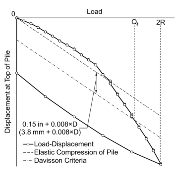
Determine
the load test ultimate bearing value (Qf)
using the Davisson criteria. First plot the displacement versus load on
the pile (Q). Next, draw a line representing the theoretical elastic
deformation of the pile, using the following equation.
|
d
= |
Q L |
|
A E |
Where:
d = Elastic deformation of pile in inches (mm)
Q = Test load in pounds (N)
L = Length of pile in inches (mm)
A = cross-sectional area of pile in square
inches (mm²)
E = Elastic modulus of pile in lb/in² (MPa)
for steel E=29,000,000 lb/in² (200,000 MPa)
Draw
the Davisson criteria line parallel to the theoretical elastic deformation but
offset by the following formula:
0.15
inch + 0.008×D (3.8 mm + 0.008×D)
Where:
D = Diameter or width of the pile in inches
(mm).
The
test load ultimate bearing value (Qf)
is the load corresponding to where the Davisson criteria line crosses the
load-displacement curve. See the figure below.
Within
four days of completing the static load test, submit a report to the Engineer
which contains the information required according to ASTM D 1143 and the load
displacement graph described above.
506.04 Basis of Payment. If the
Contractor subsequently finds it necessary to use a different hammer, the Office
of Structural Engineering will determine if an additional static load test
is necessary; the Contractor shall complete any such additional test at no
additional cost to the Department.
The
cost of furnishing test piles with thicker pile walls is included under Static
Load Test.
The
Department will pay for accepted quantities at the contract prices as follows:
Item
Unit
Description
506
Lump
Sum
Static Load Test
506
Each
Subsequent Static Load Test