ITEM 509 REINFORCING STEEL
509.01
Description
509.02
Materials
509.03 Care of
Material
509.04 Method
of Placing
509.05 Bending
509.06 Approval
of Placing
509.07 Splicing
509.08 Supports
509.09 Epoxy
Coated Reinforcing Steel
509.10 Method
of Measurement
509.11 Basis of
Payment
509.01 Description. This work consists of
furnishing and placing supports, mechanical connectors, tie wires, and
reinforcing steel of the quality, type, size, and quantity designated,
including steel dowels.
509.02 Materials. Furnish materials conforming to:
Epoxy coated reinforcing
steel................................. 709.00
Reinforcing steel,
.... deformed
bars........................... 709.01, 709.03, 709.05
Spiral reinforcing
steel............................. 709.01
or 709.08
Bar mats and wire
fabric................ 709.09, 709.10, 709.12
Plastic
supports........................................................ 709.15
For
metal bar supports used at or near the surface of the concrete, furnish either
galvanized steel, stainless steel, epoxy coated steel or plastic coated steel.
Provide
sufficient additional reinforcing steel to replace reinforcing steel removed by
the Department for sampling. Replace random samples in the structures
with additional steel, spliced according to 509.07.
When
providing reinforcing steel for spiral cages, galvanized steel conforming to ASTM A767, Class 1, may be
provided only for the spiral reinforcing steel in lieu of epoxy coated reinforcing
steel. The galvanized coated reinforcing steel will meet all other requirements
of 509. Where a sample splice is needed
use the lap length requirements for epoxy coated. The Galvanized coating
will be applied after the reinforcing has been fabricated. If the galvanized
surface becomes damaged during handling in the field, repairs will conform to ASTM A780. Use bar supports
and tie wires which are plastic coated or epoxy coated. Only suppliers
certified under S1068
may provide this reinforcing.
509.03 Care of Material. Upon delivery
to the project and before use, stack reinforcing steel off the ground and keep
it free from dirt, oil, grease, or avoidable rust. Before placing in the
concrete, ensure the reinforcing steel is clean and free of loose rust.
509.04 Method of Placing. Place
reinforcing steel in the positions shown on the plans, and firmly secure the
steel during the placing and setting of concrete. Tie bars in the
superstructure at all intersections, except tie bars at alternate intersections
where bar spacing is less than 1 foot (0.3 m) in any direction. The
Contractor may place up to 25 percent of the upper longitudinal bars in a
bridge deck slab beneath the upper transverse bars to support the top
mat. Do not drive or force reinforcing steel into concrete after its initially set.
Welding
on reinforcing is prohibited, except as permitted by 709.10 and 709.12.
The Engineer will allow the Contractor to fabricate reinforcing bar cages for prestressed beams if fabrication is done in a manner
satisfactory to the Director.
Install
reinforcing steel with at least the following clearances from the concrete
surface:
A. 2 1/2 inches (65 mm) to the top of
sidewalks.
B. 3 inches (75 mm) at the faces of
footings placed against rock or earth.
C. 1 1/2 inches (38 mm) to the bottom of
a cast-in-place deck slab.
D. 2 inches (50 mm) at all other
surfaces.
E. 2 1/4 to 2 1/2 inches (60 to 65 mm)
between the reinforcing steel and the top surfaces of cast-in-place concrete
deck slabs.
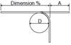
509.05 Bending. Bend
reinforcing steel to the dimensions shown on the plans and in Table 509.05-1 (509.05-1M). Reject
reinforcing steel showing transverse cracks.
|
|
Bar |
|
|
|
|||||
|
|
Nominal Dimensions |
180° Bend |
90° Bend |
135° Bend |
|||||
|
Bar |
Diameter |
Area |
Weight |
D |
A |
D |
A |
D |
A |
|
Size |
in |
in² |
lb/ft |
in |
in |
in |
in |
in |
in |
|
3 |
0.375 |
0.11 |
0.376 |
2 1/4 |
5 |
2 1/4 |
5 |
1 1/2 |
4 |
|
4 |
0.500 |
0.20 |
0.668 |
3 |
6 |
3 |
7 |
2 |
4 1/2 |
|
5 |
0.625 |
0.31 |
1.043 |
3 3/4 |
7 |
3 3/4 |
8 1/2 |
2 1/2 |
5 1/2 |
|
6 |
0.750 |
0.44 |
1.502 |
41/2 |
8 |
4 1/2 |
10 |
|
|
|
7 |
0.875 |
0.60 |
2.044 |
5 1/4 |
10 |
5 1/4 |
12 |
|
|
|
8 |
1.000 |
0.79 |
2.670 |
6 |
11 |
6 |
131/2 |
|
|
|
9 |
1.128 |
1.00 |
3.400 |
9 1/2 |
15 |
9 1/2 |
15 1/2 |
|
|
|
10 |
1.270 |
1.27 |
4.303 |
10 3/4 |
17 |
10 3/4 |
18 |
|
|
|
11 |
1.410 |
1.56 |
5.313 |
12 |
19 |
12 |
20 |
|
|
|
14 |
1.693 |
2.25 |
7.65 |
18 1/4 |
27 |
18 1/4 |
25 |
|
|
|
18 |
2.257 |
4.00 |
13.60 |
24 |
36 |
24 |
33 |
|
|
|
Tolerances: For diameter of bends, “D”, the tolerance may be plus or minus the diameter of the
bar. Standard fabricating tolerances shall be in accordance with the CRSI Manual of Standard Practice. No weight
allowances will be made for tolerances. |
|||||||||

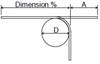

TAble 509.05-1M STANDARD BENDS
|
|
Bar |
|
|
|
|||||
|
|
Nominal Dimensions |
180° Bend |
90° Bend |
135° Bend |
|||||
|
Bar |
Diameter |
Area |
Weight |
D |
A |
D |
A |
D |
A |
|
Size |
mm |
mm² |
kg/m |
mm |
mm |
mm |
mm |
mm |
mm |
|
#10M |
9.5 |
71 |
0.560 |
60 |
130 |
60 |
130 |
40 |
105 |
|
#13M |
12.7 |
129 |
0.994 |
75 |
155 |
75 |
180 |
50 |
115 |
|
#16M |
15.9 |
199 |
1.552 |
95 |
180 |
95 |
215 |
65 |
140 |
|
#19M |
19.1 |
284 |
2.235 |
115 |
205 |
115 |
255 |
|
|
|
#22M |
22.2 |
387 |
3.042 |
135 |
255 |
135 |
305 |
|
|
|
#25M |
25.4 |
510 |
3.973 |
150 |
280 |
150 |
345 |
|
|
|
#29M |
28.7 |
645 |
5.060 |
240 |
380 |
240 |
395 |
|
|
|
#32M |
32.3 |
819 |
6.404 |
275 |
430 |
275 |
455 |
|
|
|
#36M |
35.8 |
1006 |
7.907 |
305 |
485 |
305 |
510 |
|
|
|
#43M |
43.0 |
1452 |
11.38 |
465 |
685 |
465 |
635 |
|
|
|
Tolerances: For diameter of bends, “D”, the tolerance may be plus or minus the diameter of the
bar. Standard fabricating tolerances shall be in accordance with the CRSI Manual of Standard Practice. No weight
allowances will be made for tolerances. |
|||||||||


509.06 Approval of Placing. Before
placing concrete, obtain the Engineer’s approval of reinforcing steel in place.
509.07 Splicing. Splice reinforcement only as
specified or determined by the Engineer. Splice spiral reinforcement by
lapping 1 1/2 turns. Do not replace spiral reinforcement removed for a
material sample if the sample is from the end of the spiral and less than or
equal to 30 inches (0.8 m) long.
Mechanical
connectors shall be capable of developing 125 percent of the yield strength of
the connected bars. The total slip of the bar within the splice sleeve of
the connector after loading in tension to 30.0 ksi
(207 MPa) and relaxing to 3.0 ksi
(21 MPa) shall not exceed the following measured
displacements between gage points clear of the splice sleeve:
A. For bar sizes up to No. 14: 0.01 in.
(0.25 mm)
B. For No. 18 bars: 0.03 in. (0.76 mm)
Splice
Nos. 14 and 18 (Nos. 45M and 55M) reinforcing steel bars with mechanical
connectors.
The
Department will not permit lap splices for these size bars.
Splice
Nos. 14 and 18 (Nos. 45M and 55M) reinforcing steel bars with mechanical
connectors. The Department will not permit lap splices for these size
bars.
Splice
additional steel used to replace random samples as follows:
Table
509.07-1
Table 509.07-1M
|
Bar |
Lap Length (inches) |
|
Bar |
Lap Length (mm) |
||
|
Size |
Uncoated |
Epoxy Coated |
|
Size |
Uncoated |
Epoxy Coated |
|
4 |
22 |
27 |
|
13M |
560 |
690 |
|
5 |
29 |
35 |
|
16M |
740 |
890 |
|
6 |
34 |
41 |
|
19M |
870 |
1040 |
|
7 |
43 |
52 |
|
22M |
1090 |
1320 |
|
8 |
57 |
69 |
|
25M |
1450 |
1750 |
|
9 |
72 |
87 |
|
29M |
1830 |
2210 |
|
10 |
92 |
111 |
|
32M |
2340 |
2820 |
|
11 |
113 |
137 |
|
36M |
2870 |
3480 |
509.08 Supports. Use precast mortar blocks, metal supports,
or plastic supports of adequate strength, of the proper depth, and in
sufficient number to support reinforcing steel. Space supports for
reinforcing steel no more than 4 feet (1.2 m) apart transversely and
longitudinally. Metal supports shall have a shape that is easily
enveloped by the concrete.
Mortar
blocks may only be used to support the lower matt of reinforcing steel in
concrete that is cast directly against bedrock or soil.
509.09 Epoxy Coated Reinforcing Steel. Use
plastic coated or epoxy coated bar supports and tie wires to protect the epoxy
coating from physical damage, as specified in 709.00,
during placement and to prevent electrical coupling between mats.
Carefully handle and install bars to perform minimal patching at the job site.
Repair physical damage to the epoxy coating with a patching material all
damaged coating areas greater than 1/4-inch (6 mm) square or 1/4-inch (6 mm)
diameter; approximately 1/8-inch (3 mm) square or 1/8-inch (3 mm) diameter if
the opening is within 1/4-inch (6 mm) of an equal or larger opening; or, a
length of 6 inches (150 mm) regardless of area. Coating damage in cases where
the damaged area is less than specified above need not be repaired. Use
patching material of the same composition and quality as the original coating.
Prepare the surface to a near white metal.
If
repair is required, clean and repair the damaged areas and allow adequate cure
time before placing concrete. The Engineer will approve the installation
once patching has been done as outlined above.
509.10 Method of Measurement. The Department
will measure Epoxy Coated Reinforcing Steel by the number of pounds (kilograms)
shown on the plans. Additional measurements or calculations are not
required.
If
the Contractor believes the pay weight, as shown on the plans, is in error, the
Contractor is responsible to prove this discrepancy by recalculating the total
weight for the reference number involved. The Contractor shall submit its
figures to the Engineer for review and approval. The number of pounds
(kilograms) of reinforcing steel shall be the actual number of pounds
(kilograms) of the various sizes incorporated in the concrete as shown on the
plans, completed and accepted.
If
the weight of the reinforcing steel is recalculated, determine the number of
pounds (kilograms) from the number, length, and weight of the bars as shown on
the steel list of the plans, based on the weight per foot (meter)
shown in the Table 509.05-1 (509.05-1M) with
deductions for bars not used, and addition for extra bars used as directed by
the Engineer.
509.11 Basis of Payment. The
Department will not include the supports, mechanical connectors, and tie wires
in the calculated weights but will consider them incidental to the price bid.
The
Department will pay for accepted quantities at the contract price as follows:
Item
Unit
Description
509
Pounds (Kilograms) Epoxy Coated
Reinforcing