ITEM
511 CONCRETE FOR STRUCTURES
511.01
Description
511.02
Materials
511.03 Concrete
511.04 Quality
Control Requirements
and Mass
Concrete
511.05 Mixing
of Concrete
511.06 Slump
511.07 Placing
Concrete
511.08 Slipform Construction of Bridge Railing
511.09
Construction Joints
511.10 Work
Stoppage
511.11
Depositing Concrete Under Water
511.12
Depositing and Curing Concrete During Cold Weather
511.13 Removal
of Forms
511.14
Curing and Loading
511.15 Surface
Finish
511.16 Roadway
Finish
511.17 Bridge
Deck Grooving
511.18 Sidewalk
Finish
511.19 Sealing
Joints and Cracks
511.20
Compressive Strength
511.21 Air
Content
511.22 Pay
Factors
511.23 Method
of Measurement
511.24 Basis of
Payment
511.01 Description. This work consists of
providing falsework and forming, furnishing, placing,
consolidating, finishing, and curing portland
cement concrete. This work also includes diamond saw cutting longitudinal
grooves into the surface of superstructure concrete. Construct falsework and forms as required in Item 508.
511.02 Materials.
Furnish materials conforming to 499.02,
except as modified below.
Use the same
kind and color of aggregate for all concrete above the ground line in a given
substructure unit and for all concrete in a given superstructure.
Use high molecular
weight methacrylate resin sealer conforming to 705.15.
Use curing
materials conforming to 705.05; 705.06 (white opaque); or 705.07;Type 1 or
1D.
Use 1/4-inch (6
mm) gray sponge joint filler conforming to 711.28,
or use preformed filler conforming to 705.03.
Use
preformed elastomeric compression joint seals conforming to 705.11.
511.03 Concrete. Provide concrete for structures
according to 499.03, using Class QC 1, QC
2, QC 3 or QC 4 as specified in the Contract.
At
least 10 days before placing concrete, submit, in writing, the Department
accepted Job Mix Formula (JMF) to the Engineer.
The Engineer will review the mix design for conformance to contract
requirements; otherwise the mix design is for the Engineer’s information.
511.04 Quality Control Requirements and Mass Concrete. When the
concrete bid item requires QC/QA, develop and submit a Quality Control plan (QCP) for the work and perform quality control testing of
the concrete conforming to Item 455.
When
the concrete bid item requires QC/QA, The Engineer will perform Quality
Assurance conforming to 455.
When
the concrete bid item does not require QC/QA, the Engineer will make acceptance
test cylinders as follows:
1.
Structures over 20-foot (6.1 m) span. A set of test cylinders
from each 200 cubic yards (150 m³) of concrete, or fraction thereof that
is incorporated into the work each day.
2.
Structures of 20-foot (6.1 m) span or less. At least one set of test cylinders
for each 50 cubic yards (35 m³) of concrete.
With
any 511 concrete bid item provide and maintain a
Concrete Cylinder Curing Box (CCCB) capable of
holding at least 12 4 × 8 inch (100 × 200 mm) cylinders at a temperature of 60
to 80 °F (15 to 27 °C) degrees no matter what the ambient temperature.
The box will have a sealed lid. If the project has numerous 511 concrete bid items CCCB
are not required for each bid item. Locate the CCCB
at a site that is convenient to the concrete work and will eliminate handling
damage to both the Contractor QC or QA cylinders and the Department
Cylinders. Move the CCCB as needed during the
project when the distance from the concrete work increases the possibility of
cylinder handling damage.
A. Mass Concrete
Requirements.
For concrete components with a minimum dimension of 5-ft (1.5-m) or greater,
develop a concrete mix design QC-4 for mass concrete according to 499.03. Develop a Thermal Control Plan (TCP)
to control placement of the mass concrete so that the highest maximum internal
temperature of the placed concrete is not greater than 160⁰
F (71⁰ C) and the maximum differential
concrete temperature does not exceed 36⁰ F (20⁰
C) over 28 days from time of placement.
For
drilled shafts with a dimension of 7-ft (2.1-m) diameter or greater, develop a
concrete mix design QC-4 for mass concrete, QC 4 according to 499.03. Develop a TCP to control placement
of the mass concrete so that the highest maximum internal temperature of the
placed concrete is not greater than 160ºF (71ºC).
Submit
the TCP to the Engineer for acceptance at least 10 calendar days prior to
placement along with the approved JMF (s).
As
a minimum, the TCP shall include the following information:
1.
Duration and method of curing.
2.
Procedures to control concrete temperature at the time of placement. The mix
shall contain no frozen pieces of ice after blending and mixing components.
3.
Methods and equipment used for controlling temperature differentials.
4.
Temperature sensor types, locations and installation details. As a minimum,
concrete temperatures shall be monitored at the calculated hottest location, on
at least 2 outer faces, 2 corners, and top surfaces.
5.
Temperature monitoring and recording system; operation plan; recording and
reporting plan with example output; and a remedial action plan.
Criteria for form removal to control the
maximum temperature differential.
As
an alternative to the maximum differential concrete temperature specified
above, the Contractor may propose maximum differential temperature limits based
on strength gain with time. The TCP for the alternative proposal
shall include the methods used to determine the temperature and supporting data
and design to support the accuracy of the method chosen. Provide complete
calculations and basis for increasing the maximum differential temperature
specification. The TCP for the alternative proposal shall also provide the
Engineer with tables that define ambient temperatures for acceptable concrete
placement, the required temperature of the concrete for the ambient air
temperature, the maximum predicted concrete temperature, the maximum predicted
differential temperature, the time for removal of forms, the allowable air
temperature for form removal, and the predicted maximum and differential
temperature from placement to age of 28 days. The Department will
consider all cracking of a mass concrete placement where the differential
temperature exceeded 36 ºF (20ºC) the responsibility of the Contractor.
Upon
the Engineer’s acceptance of the TCP, continuously monitor all temperature
sensors over the required age of the concrete. If the maximum limit or
differential temperature limits are exceeded at any time, immediately take
action to retard and reduce the out-of-specification temperatures. If a
mass concrete placement temperature exceeds the specification limits of the
currently accepted TCP, re-engineer, revise and resubmit the TCP. Do not
place additional mass concrete until the revised TCP is accepted.
The
Department will consider in-place mass concrete that exceeds the temperature
limits or that cracked, as defective and resulting delays as non-excusable.
Determine the extent and effect of the damage and submit a proposed repair plan
to the Engineer to return the concrete to acceptable quality. The
Department will determine if the proposed repair methods are acceptable or if
removal is required.
511.05 Mixing of Concrete. Mix concrete
according to 499.08.
When
an air temperature of 60 °F (16 °C) or higher prevails at the time of placing
concrete in a bridge superstructure over 20-foot (6.1 m) span, add a chemical
admixture conforming to 705.12, Type B or
D to the concrete unless waived by the Engineer.
511.06 Slump. Within the slump ranges specified
in 499.03, provide a slump that produces concrete
that is workable in the required position, flows around reinforcing steel, and
coats individual particles of coarse aggregate with mortar containing the
proportionate amount of sand.
511.07 Placing Concrete. Submit to
the Engineer a description of proposed placing procedures and notify the
Engineer at least 24 hours in advance of placing concrete. If the
concrete bid item requires QC/QA, include the submittal as part of the QCP.
Place and finish concrete to the lines
and grades shown in the plans.
Provide coverage over or around
reinforcing steel as described in 509.04.
Conform to the following tolerances from
plan dimensions:
PLACEMENT TOLERANCES
|
Deviation from plumb for exposed surfaces |
± ¾ inch (19 mm) |
|
Vertical alignment (Deviation from a line parallel to the grade
line) |
± ½ inch in 20 feet (13 mm in 6 m) |
|
Longitudinal alignment (Deviation from a line parallel to the
centerline or baseline) |
±½ inch in 20 feet (13 mm in 6 m) |
|
Width dimensions of walls for exposed surfaces |
±½ inch |
|
Bridge Slab thickness |
±¼ inch (6 mm) |
|
Elevations of beam seats |
±1/8 inch (3 mm) |
|
Slope, Vertical Deviation from Plane |
±0.2% |
|
Slope, Horizontal Deviation from Plane |
±0.4% |
Until
discharged in the work, ensure that the temperature of all concrete does not
exceed 95 °F (35 °C). .
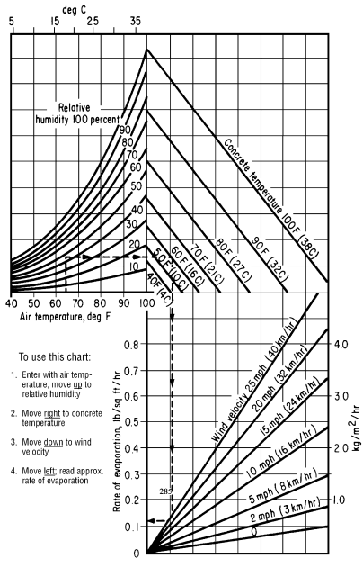
When
placing superstructure concrete assure the ambient air temperature is 85 °F (30
°C) or less and not predicted to go above 85 °F (30 °C) during the concrete
placement; and evaporation rates, determined according to Figure 1 in ACI 308,
do not exceed 0.1 lbs/ft2/hour (0.5 kg/m2/hour).
Determine
and document the ambient air temperature, concrete temperature, deck surface
temperature, relative humidity, and wind velocity, subject to verification by
the Engineer. Measure data required in Figure
1 from within 10 feet (3 m) of the area where the superstructure concrete
is placed.
Figure 1 does not apply to substructure items
and formed parapets. Figure 1 applies
to slip-formed parapets.
To
meet favorable atmospheric conditions, may require the Contractor to place
concrete at night. At least 24 hours before placing concrete at night,
submit a lighting plan for the work area to the Engineer. Obtain the
Engineer’s approval of the lighting plan before placing the concrete. Direct lights so that approaching traffic is not affected or
distracted.
Before
placing a concrete deck on continuous steel beams or girders, complete all of
the main beam or girder splices at least two piers beyond the pier or piers
supporting the concrete.
Before
placing concrete for backwalls above the approach
slab seat with steel expansion joints, backfill the abutments to within 2-feet
(0.6 m) of the bridge seat elevation, erect structural steel or prestressed concrete beams and place superstructure
concrete in the adjacent span,. Use the steel expansion joint as a
template for the top of the backwall. If
temporary bolts are used to support the backwall
portion of an expansion device during the placing of the backwall
concrete, remove the bolts after the concrete has taken its initial set and
before a change in temperature causes superstructure movement sufficient to
damage the backwall.
Before
placing concrete, assure the Engineer of an adequate and uniform source of supply
of concrete to allow proper placing and finishing, and of the availability of
coverings to protect the concrete from rain.
Do
not add or apply water to the concrete after it has left the truck and before
applying curing materials according to 511.14.
Before
placing concrete, thoroughly clean all forms and structural steel that contact
the concrete and ensure that the space to be occupied by the concrete is free
of laitance, silt, dirt, shavings, sawdust, loose and built-up rust, and other
debris.
Deposit
concrete using methods that ensure reinforcing steel is completely enveloped in
concrete mortar and that allow inspection of concrete enveloping the
reinforcing steel. Use a method or device to convey the concrete from the
mixer to the work that prevents coarse aggregate separating from the
mortar. If depositing concrete in shallow members, such as slabs, place
it with as short a vertical drop as possible. Place the concrete over a
section to maintain a practically horizontal surface. If using a chute,
slope the chute to allow concrete to flow without segregation. Place
concrete as near as possible to its final position.
Drop
concrete into the forms with a free-fall distance of 5 feet (1.5 m) or
less. As necessary, use drop chutes to limit the free fall to 5 feet (1.5
m) and to ensure the delivery ends as vertical as possible.
Deliver
and distribute the concrete at a uniform and adequate rate no more than 10 feet
(3 m) directly in front of the finishing machine by suitable mechanical
equipment. For structures with a skew angle greater than fifteen (15) degrees,
Orient the finishing machine according to 511.16.
For structures with a skew angle greater than fifteen (15) degrees and up to
fifty (50) degrees, load the concrete at the skew angle. For structures
with a skew angle greater than fifty (50) degrees, load the concrete as close
to the skew angle of the structure as possible, but do not allow the leading
edge of the concrete placement to exceed twenty (20) feet (6.1 m) ahead of the
finishing machine.
Place
concrete in structures using vibration. Furnish and use sufficient
vibration equipment of the type and size approved by the Engineer to properly
compact the concrete immediately after it is placed in the forms. The
vibrators shall generally be of a type that is applied directly to the concrete
and have a frequency of at least 4500 impulses per minute. If the
concrete is inaccessible for this method of vibration, apply the vibrators to
the outside of the forms.
Do
not move concrete using a vibrator. Vibrate freshly deposited concrete at
the point deposited. Slowly insert and withdraw the vibrators vertically
into the concrete until the concrete is thoroughly compacted but not
segregated. During vibration, do not disturb partially hardened concrete.
As necessary, spade along form surfaces,
in corners, and in locations impossible to reach with vibrators to ensure
smooth surfaces and dense concrete. Closely observe the results
obtained on the first concrete placed, and, if necessary, modify the mix
according to this specification to secure the best results.
511.08 Slipform Construction of
Bridge Railing.
If slipforming, provide finished concrete conforming
to the following tolerances from plan dimensions:
SLIPFORMED BRIDGE RAILING TOLERANCES
|
Reinforcing steel cover |
-1/2 inch, +1/2 inch (-13 mm, +13 mm) |
|
Top width dimension |
-0, +1/4 inch (+6 mm) |
|
Bottom width dimension |
-0, +1/2 inch (+13 mm) |
|
Surface flatness |
1/4 inch in 10 feet (6 mm in 3 m) |
|
Vertical alignment (Deviation from a line parallel to the
grade line) |
1/2 inch in 20 feet (13 mm in 6 m) |
Tie
all joints and splices in bridge railing reinforcing steel. Before
placing concrete, perform a slipforming dry run to verify
reinforcing clearance and rigidity of the reinforcing cages. Adjust and
stabilize the cage as necessary to establish the required clearances and to
ensure the cage will not move during slipforming.
The Contractor may add any additional diagonal reinforcing steel between the
front and rear vertical reinforcing faces to establish the required rigidity.
Repair
or patch honeycombing, cracking, tearing, and other defects immediately after
concrete exits the slipform equipment.
Completely fill defects with concrete without using water to smooth or close
the surface. If the slipforming exhibits more
than infrequent defects, stop work and make adjustments to produce a slipformed surface that does not require repairs. Do not broom finish the surface of the bridge railings.
After
the concrete initially sets, but before any shrinkage cracks develop, saw
control joints 1 1/4 inches (32 mm) deep into the perimeter of the
parapet. Generally, initial set is within 6 hours of batching of the
concrete. Ensure that all joints are sawed within 24 hours of placement.
Saw control joints using an edge guide, fence, or jig to ensure that the joint
is straight, true, and aligned on all faces of the parapet. The joint
width shall be the width of the saw blade, a nominal 1/4 inch (6 mm).
Caulk the control joints with a polyurethane or polymeric material conforming
to ASTM C 920, Type S.
Slip
formed concrete requires different slumps than those listed in Item 499 or other plan specified concrete. Provide a
slump such that the concrete exiting the slipform
does not pull but is stiff enough to prevent waviness and sags in the finished
surfaces. Cure slipform concrete according 511.14, Method A. Because slipformed concrete has a low water-cement ratio, timely
application of the water cure is critical in helping control shrinkage cracks.
Furnish
platforms as necessary to protect traffic passing under the bridge from falling
debris during the slipforming operation, to allow
access for completing the finishing operation, and to allow the Engineer access
to the outside of the parapet.
The
Engineer will inspect the slipformed surface for
horizontal cracking no earlier than 21 days after completion of the slipforming operation. Repair all horizontal cracks
by epoxy injection. If a concrete sealer was applied,
repair damage to the sealer after completing the epoxy injection.
511.09 Construction Joints. If
construction joints are shown on the plans, place all concrete between
consecutive joints in a continuous operation. Do not place concrete
against a joint for at least 12 hours, or as required by 511.14.
Obtain
the Director’s approval before placing any construction joint not shown on the
plans or required by 511.07.
Before
placing concrete, determine the location where the day’s concrete placing
ends. If practical, end placing the day’s concrete perpendicular to the
lines of principal stress and in regions of small shear. Do not install
horizontal joints in concrete girders and beams.
Form
construction joints using bulkheads with keyways. Locate keyways clear of
exposed surfaces by approximately one-third the thickness of the joint.
Where
practical, avoid horizontal joints in piers, abutments, and retaining walls, otherwise locate horizontal joints 2 feet
(0.6 m) or more above the normal water level.
For
construction joints not shown on the plans and above ordinary low water, in
abutments, and in retaining walls that retain earth fills, install a 36-inch (1
m) strip of Type 2 membrane waterproofing according to Item 512
to the back of the joint.
Avoid
joints in cantilevered members.
Dampen
the surface of the concrete of the horizontal construction joints immediately
before placing adjoining concrete.
Place
and protect horizontal construction joints between bridge slabs and
superimposed curbs, parapets, sidewalks, and median strips in the same manner
as the remainder of the slab. Cure the construction joints according to 511.14.
Avoid
disturbing the bond between protruding reinforcing steel and the deck concrete.
If using the curb areas to place the deck, tie and brace the reinforcing steel
to prevent its movement.
Where
walls or columns support slabs or beams, place concrete in wall or column to
the bottom of the slab or beam and allow the concrete to settle for at least 2
hours before placing concrete in the slab or beam.
511.10 Work Stoppage. If the work is
unexpectedly interrupted by breakdowns, storms, or other causes, rearrange the
freshly deposited concrete to provide a suitable construction joint. If
this joint occurs at a section with shear stress, prevent a plane of weakness
by providing an adequate mechanical bond across the joint by forming a keyway,
inserting reinforcing steel, or by some other means satisfactory to the
Engineer.
511.11 Depositing Concrete Under Water. Except
for cofferdam seals and drilled shafts, do not place concrete under water.
511.12
Depositing and Curing Concrete During Cold Weather. If
placing concrete when the atmospheric temperature is 32 °F (0 °C) or less, or
if weather forecasts predict these temperatures during the curing period,
follow the procedures of this subsection.
Heat
the water or aggregate, or both, as necessary to produce concrete with a
temperature when placed of at least 50 °F (10 °C) but not greater than 70 °F
(21 °C).
Place
concrete against materials with a temperature of greater than 32 °F (0
°C). If necessary, heat the forms, reinforcing steel, and foundation
materials before placing the concrete.
Maintain
the concrete surface temperature between 50 and 100 °F (10 and 38 °C) for
a period of not less than 5 days, except as modified in 511.12.C. After the minimum cure period of
5 days, reduce the concrete surface temperature at a rate not to exceed 20 °F
(11 °C) in 24 hours until the concrete surface temperature is within 20 °F (11
°C) of atmospheric temperature.
Install
sufficient high-low thermometers to readily determine the concrete surface
temperature. For deck slabs, install high-low thermometers to measure
deck bottom surfaces, deck fascia surfaces, and deck top surfaces.
Maintain
the concrete curing temperature using a heated enclosure, insulated forms, or
by flooding, except cure deck slabs less than 10 inches (250 mm) thick using more
than just insulated forms.
Remove
falsework and open cold weather concrete to traffic
according to 511.14.
A. Heated Enclosure. Construct the heated enclosure to surround the
top, sides, and bottom of the concrete. Construct strong and wind proof
enclosures that contain adequate space to allow free circulation of air around
the forms and concrete.
Before placing
concrete, construct the enclosure and heating devices to the extent allowed by
the concrete operation. As the concreting operation progresses and as
soon as possible after placing concrete, complete construction of the
enclosures and apply heat. Supply heat by a method that continuously
maintains a reasonably uniform temperature throughout the enclosures and does
not discolor the concrete.
Vent combustion-type
heating devices outside the enclosure.
If dry heat, other
than free steam, maintains the enclosure temperature, immediately cover exposed
concrete with two thicknesses of burlap. Continuously wet the burlap and,
except for required rubbing of the concrete, do not remove the burlap during
the heating period.
If wood forms without
liners are left in place more than 2 days after the placing of concrete,
thoroughly wet the forms at least once each day for the remainder of the
heating period. If forms are removed during the heating period,
thoroughly drench the concrete with water and, for the remainder of the heating
period, cover and wet the concrete with burlap as specified above.
B. Insulation. Install sufficient thermometers to readily
determine the concrete surface temperature. If the surface temperature
approaches 100 °F (38 °C), loosen or otherwise vent the forms or insulation to
keep the surface temperature within the limits specified above. If
insulation does not maintain the minimum required temperature, promptly enclose
the concrete as specified in 511.12.A or flood
the concrete as specified in 511.12.C.
Use a wind and water
resistant insulating material. Ensure edges, corners, and other points of
extreme exposure are adequately insulated. Place a tarpaulin or other
Engineer approved waterproof cover over the insulation to protect the concrete
top surface.
C. Flooding with Water. The Contractor may flood the concrete with
water provided flooding does not damage the concrete. Heat the water to a
temperature from 50 to 100 °F (10 to 38 °C). The Contractor may stop
using heated water after 48 hours if the concrete remains flooded to a depth of
1 foot (0.3 m) above its highest elevation for at least the next 120 hours.
511.13 Removal of Forms. To
facilitate finishing, remove forms from vertical surfaces that receive a rubbed
surface finish as soon as the concrete has hardened sufficiently that rubbing
will not damage it.
511.14
Curing
and Loading.
Remove falsework and open structures to traffic only
after the concrete has reached the strength specified by Table 511.14-1A for concrete bid items requiring
QC/QA. Use Table 511.14.1B for concrete
items not requiring QC/QA. Do not shorten the minimum required Method A curing time
regardless of strength test results.
|
Loading requirements For concrete requiring QC/QA |
||
|
|
Span[1] |
Required Strength [2] |
|
Removing Falsework |
Any Span |
Compressive Strength ≥ 0.85% f’c orFlexural Strength (Center point) ≥ 650 psi (4.5 Mpa) |
|
All pier caps |
||
|
Traffic [3] |
Any |
|
|
[1] Span is defined as the
horizontal distance between faces of the supporting elements when measured
parallel to the primary reinforcement. |
||
|
[2] Field cured samples.
The maturity curve method may be used for determining the strength according
to Supplement 1098 in lieu of field curing samples |
||
|
[3] When placing concrete
for a superstructure between October 15 and March 15, open the deck to
traffic no sooner than 30 days after placement. |
||
|
Loading requirements for concrete not requiring qc/qa |
|||
|
|
Span[1] |
Age of Concrete in Days |
|
|
No Beam Test |
Beam Test [2] |
||
|
Removing Falsework |
Over 10 feet (3 m) |
14 |
5 |
|
10 feet (3 m) or less and all pier caps |
7 |
3 |
|
|
Traffic [3] |
Any |
14 |
7 |
|
[1] Span is defined as the
horizontal distance between faces of the supporting elements when measured
parallel to the primary reinforcement. |
|||
|
[2] Applicable only when the
average modulus of rupture for two tests is not less than 650 psi (4.5 MPa). |
|||
|
[3] When placing concrete
for a superstructure between October 15 and March 15, open the deck to
traffic no sooner than 30 days after placement. |
|||
Take
enough specimens to verify compliance with the strength requirements of Table 511.14-1A. Obtain samples from the
first and last sublots of continuously placed
concrete for quantities of 500 yd3 or less, and one extra set of
specimens for each additional 500 yd3 or fraction thereof.
Obtain samples in equally spaced increments throughout the placement as
directed by the Engineer. Delays in placements of more than 4 hours are
not considered continuously placed and are to be treated as separate
placements.
If
the air temperature surrounding the concrete is maintained between 32 and 50 °F
(0 and 10 °C), and if the provisions of 511.12 do
not apply, maintain the concrete above 32 °F (0 °C) for 7 days or until a
successful strength test conforming to Table
511.14-1, except this time shall not be less than 5 days.
Do
not install compression rings on pier columns or similar items of construction
for supporting falsework or subsequent construction
until after a 72-hour curing period.
Do
not apply loads to or perform work on new concrete until workers and construction materials will not damage the concrete
or interfere with its curing. Allow at least 36 hours or until the field
cured compressive strength cylinders or maturity results reach 85% f’c; or if using flexural beams, or the average of two beam
tests is greater than 650 psi (4.5 MPa) before
working on new concrete. Do not interfere with curing of new concrete.
Cure
concrete as follows:
|
CURING REQUIREMENTS |
|
|
Location |
Curing Method [1] |
|
Superstructure concrete |
|
|
Concrete to which sealer is applied |
|
|
Construction joints |
|
|
Top surface of concrete deck superstructure concrete |
|
|
Concrete with waterproofing |
|
|
All other concrete |
|
|
[1] Method A is water curing. Method B is membrane curing. If using Method B on areas to be waterproofed, remove
the curing membrane. |
|
Concrete
curing methods are as follows:
A. Method A, Water Curing. With the exception of the top surface of deck
superstructure concrete, protect surfaces not covered by forms immediately
after final finishing with two thicknesses of wet burlap. Keep burlap wet
for at least 7 days by the continuous application of water. If forms are
removed before 7 days, immediately drench the exposed concrete with water and
cover it with burlap. Continuously apply water to the burlap for the
remainder of the curing period.
Instead of continuous
application of water, with the exception of the top surface of deck
superstructure concrete, the Contractor may cover the wet burlap with white
polyethylene sheeting or plastic coated burlap blankets conforming to
705.06. Place plastic coated burlap blankets wet and with the burlap side
against the previous layer of wet burlap. Sufficiently lap and secure
adjoining plastic coated blankets or polyethylene sheets at the laps and edges
to form a seal that maintains the concrete wet at laps and edges. Cover
white polyethylene sheeting or plastic coated blankets containing holes or
tears with an additional covering of plastic sheeting or blankets as directed
by the Engineer.
Cover the top surface
of deck superstructure concrete with a single layer of clean wet burlap after
it is bull floated if necessary, and finished. Keep the burlap wet by a
continuous flow of water through soaker hoses and cover the hoses with a 4 mils (100 mm) white opaque polyethylene film for 7
days. After 7 days, allow the surface of the deck to dry.
After curing the top
surface of the deck superstructure concrete for 7 days, remove the burlap and
standing water. Within 12 hours after removing the burlap, apply a curing
membrane and cure the concrete according to Method B.
B. Method B, Membrane Curing. Immediately after the free water has
disappeared on surfaces not protected by forms, apply curing material
conforming to 705.07, Type 1 or 1D.
If forms are removed before the end of the 7-day curing period, apply curing
material on the concrete exposed by removing the forms.
Thoroughly mix curing
material immediately before use. Apply the membrane curing material at
the rate of at least 1 gallon per 200 square feet (1 L/5 m2) of
surface and in a fine mist to provide a continuous, uniform, and water
impermeable film without marring the concrete surface
Do not allow workers,
materials, and equipment on the concrete during the curing period, unless
adequately protecting the membrane curing material from damage. .
If the film is
broken or damaged during the specified curing period, reapply curing material
as specified above to the damaged or affected areas.
511.15 Surface Finish. Immediately
after removing forms, clean, dampen, and fill with mortar all cavities produced
by form ties, honeycomb spots, broken corners or edges, and other defects.
Use a mortar of the same proportions used in the concrete being finished.
Substitute sufficient white cement for the regular cement in the mortar used to
fill holes and perform other corrective work to produce finished patches of the
same color as the surrounding concrete. Finish other contiguous exposed
surfaces on the structure in a similar manner and to the extent required to
produce a uniform appearance.
On all exposed surfaces,
remove fins and irregular projections with a stone or power grinder, taking
care to avoid contrasting surface textures.
A. Grout Cleaning. If grout cleaning is shown on the plans or
necessary for corrective work, wet the concrete surface and then uniformly
cover the concrete with a grout consisting of one
part cement, 1 1/2 parts fine sand conforming to 703.03, and sufficient water
to produce a mortar with the consistency of thick paint. Use white portland cement in the grout in
the quantity determined by the Engineer necessary to match the color of the
concrete. Uniformly apply the grout with brushes or spray guns,
completely filling air bubbles and holes. Immediately after applying the
grout, vigorously scour the concrete surface with a cork or other suitable
float. While the grout is still in a plastic condition and while the
grout does not pull from the holes or depressions, finish the surface with a
sponge rubber or other suitable float, removing excess grout. After the grout
thoroughly dries, vigorously rub the surface with dry burlap, removing dried
grout until there is no visible film of grout remaining on the surface.
Perform the entire cleaning operation of each area on the same day.
Remove dark spots or streaks that remain after the cleaning operation using a
fine grained silicon carbide stone. Stop rubbing with the silicon carbide
stone before the surface texture changes. Unless otherwise directed by
the Engineer, perform grout cleaning during the final project clean up.
B. Rubbed Finish. If a rubbed finish is shown on the plans, if
possible, remove forms within 2 days after placing concrete. Finish the
surface as specified above to correct defects. After the mortar used for
finishing is thoroughly set, and for a minimum of 2 hours before starting the
rubbed finish, thoroughly saturate the concrete with water.
Rub surfaces to be finished with a medium coarse silicon carbide stone
until all form marks, projections, and irregularities are removed, all voids
are filled, and a uniform surface is obtained. Leave the paste produced
by rubbing in place. Other than water, do not apply additional material
to the surface. After placing concrete above the finishing area, obtain
the final finish by rubbing the concrete with a fine silicon carbide stone and
water until the entire surface is of a smooth texture and uniform in
color. Protect surfaces with a rubbed finish from damage caused by
subsequent construction operations. If damaged, clean and refinish the
surface as specified above.
511.16 Roadway Finish. Finish and test concrete
deck slabs according to 451.12. Do not groove or broom finish a strip of surface 9 to 12
inches (220 to 300 mm) wide adjacent to curbs and barriers. Provide a
broom drag finish on concrete deck slabs in the longitudinal or transverse
direction.
The Engineer
will approve the finishing machine. Provide a self-propelled machine with
forward and reverse drive mechanisms that enable precise control of machine
velocity in both directions. The machine shall have two rotating rollers,
leveling augers, and either a vibrating pan or vibrating rollers. Field verify that the vibrating frequency of the pans or rollers
are from 1500 to 5000 pulses per minute. Do not use vibrating rollers
that have fins protruding more then 1/4 inch (6 mm) from the roller. Use
a finishing machine capable of finishing transversely while traveling in both
directions across the deck. Provide screeds capable of rising above the
concrete surface. Provide a finishing machine capable of finishing the
full width of the decks between curbs or parapet walls. The wheels of the
finishing machine shall run on temporary riding rails adequately supported on
the structural steel or falsework of the deck.
Make the rail and rail supports of steel and arrange the rail and rail supports
so that the weight of the finishing machine and the operator cause zero
vertical deflection while traveling across the deck. Ensure the rail is
straight, with no sections exceeding a tolerance of 1/8 inch in 10 feet (3 mm
in 3 m) in any direction. Elevate support rails a sufficient distance
above the slab to allow the simultaneous hand finishing of areas not machine
finished. Fabricate and install rail supports to allow removal to at
least 2 inches (50 mm) below the top of the slab. Fill holes formed by
the removal of rail supports during the final finishing of the slab.
For structures
with a skew angle greater than fifteen (15) degrees and up to fifty (50) degrees,
place the finishing machine within 5°of the skew angle of the structure.
For structures with a skew angle greater than fifty (50) degrees, place the
finishing machine at fifty (50) degrees.
511.17 Bridge Deck Grooving. After
water curing the concrete and either before applying curing compound or some
period after applying curing compound and before opening the bridge to traffic,
saw longitudinal grooves into the deck. If sawing grooves after applying the
curing compound and the concrete deck is less than 30 days old, reapply the
curing compound after removing standing water, within 12 hours after sawing
grooves in the deck.
Use diamond
blades mounted on a multi-blade arbor on self-propelled machines that were
built for grooving of concrete surfaces. The groove machines shall have depth
control devices that detect variations in the pavement surface and adjust the
cutting head height to maintain the specified depth of the groove. The grooving
machines shall have devices to control alignment. Do not use flailing or impact
type grooving equipment. More than one size grooving machine may be required in
order to saw the grooves as specified.
Provide an experienced technician
to supervise the location, alignment, layout, dimension, and grooving of the
surface.
Saw grooves parallel to the bridge
centerline in a continuous pattern across the surface. Begin and end sawing 9
to 12 inches (220 to 300 mm) from any device in place in a bridge deck, such as
scuppers or expansion joints. Stop sawing a minimum of 2 inches (50 mm) to a maximum of 24 inches (600 mm) from skewed
expansion joints. Maintain a clearance of a minimum of 2 inches (50 mm) and a
maximum of 4 inches (100 mm) from the grooves to longitudinal joints in the
deck. Maintain a minimum clearance of 9 inches (220 mm) to a maximum of
30 inches (750 mm) clearance between the grooves and the curb or parapet toe. However, at no point shall un-grooved portions of
deck extend beyond edge line and into the temporary or permanent travelled
lanes. Saw grooves in a uniform pattern spaced at 3/4 inch minus
1/4 inch or plus 0 (19 mm minus 6 mm or plus 0). Saw grooves approximately 0.15
inches (4 mm) deep and 0.10 inches (3 mm) wide.
For staged, or phase bridge deck work,
saw the grooves parallel to the final, permanent bridge centerline. If the
different stages or phases of the bridge deck work occur within one
construction season, any stage opened to traffic shall receive an interim
coarse broom finish during placement, then saw the
longitudinal grooves after the final stage. The interim broom finish will not
be allowed as a surface texture when opened to traffic over a winter season.
Saw longitudinal grooves in the deck prior to opening to traffic for a winter
season.
For bridge decks that widen from one end
to the other, saw the longitudinal grooves parallel to the centerline of the
roadway. On the side of the bridge that widens, saw the longitudinal grooves to
follow the edge line. Saw longitudinal grooves in the gore areas, avoiding the
overlapping of grooves.
At the beginning
of each work shift, furnish a full complement of grooving blades with each saw
that are capable of cutting grooves of the specified width, depth, and spacing.
If
during the work, a single grooving blade on a machine becomes incapable of cutting
a groove, continue work for the remainder of the work shift. The
Contractor is not required to cut the groove omitted because of the failed
blade. Should two or more grooving blades on a machine become incapable
of cutting grooves, cease operating the machine until it is repaired.
Continuously
remove all slurry and remaining residue from the grooving operation and leave
the deck surface in a clean condition. Prevent residue from grooving
operations from flowing across shoulders or across lanes occupied by public
traffic or from flowing into gutters or other drainage facilities. Remove
solid residue before the residue is blown by passing traffic or by wind.
Provide
water as necessary to saw grooves according to this subsection.
511.18 Sidewalk Finish. After placing, strike off
the concrete with a template and finish the concrete with a float to produce a
sandy texture.
511.19 Sealing Joints and Cracks. After
completing all curing operations and allowing the deck to thoroughly dry, seal
the following areas with a high molecular weight methacrylate (HMWM) sealer as specified in Item 512
before opening the deck to traffic:
A.
Transverse joints in the deck.
B.
Joints between the concrete deck and steel end dams.
C.
Longitudinal joints in the deck.
D.
Longitudinal joints between the deck and safety curb, barriers, and parapets,
etc.
E.
Cracks discovered in the deck that will be checked on the top and bottom
surface before opening the deck to traffic.
511.20 Compressive Strength. Sample and test
concrete strength according to 511.04.
A. Concrete
Requiring QC/QA.
When the bid item requires QC/QA, the Engineer will evaluate the QC compressive
test sublot results according to Supplement
1127 and as follows:
If a single reported compressive strength test result for a sublot of concrete is less than 88% f’c reevaluate the in-place concrete as follows:.
The
Engineer will determine the location for evaluating the strength of the sublot represented by the low compressive strength
concrete. Evaluate using either nondestructive testing or cores. The Engineer
will accept the concrete if the reported nondestructive test results are
greater than the specified f’c. The Department will
use the original cylinder results for calculating the compressive strength pay
factor (PFc) if non-destructive
testing is used. If cores are tested the core results will be used in place of
the original cylinder results for pay factor determination.
If
the nondestructive test results are less than the specified f’c,
the Department will require the concrete to be cored. The Engineer will
determine the locations for the required concrete cores. Provide all concrete
cores to the Engineer for testing by the Department. Patch core holes with
approved patching material. If the core results are above 88% f’c, the Department will use the core strength results for
calculating the compressive strength pay factor (PFc).
If
the core results indicate that the compressive strength of the concrete is
below 88% f’c, submit a plan for corrective action to
the Engineer for approval. If the corrective plan is not approved, the Engineer
will require the Contractor to:
1.
Remove and replace the unacceptable sublot and retest
the new sublot at no cost to the Department or
2.
Leave the unacceptable material in place and pay for the sublot
with a pay factor of 0.75.
If
three or more sublot compressive strength acceptance
test results are less than f’c but greater than 88% f’c the Engineer will require an investigation of the
reasons for the consistent low strengths. Until the investigation is completed
to the satisfaction of the Engineer no additional placements of the concrete JMF will be made. Investigations should include all facets
of the concrete operation including batching, mixing, delivery, clean up,
sampling, testing, quality control plan, etc. If the Engineer is
unsatisfied with the results of the investigation, the JMF
and the quality control plan will become not approved. Develop and submit a new
JMF and quality control plan conforming to the
requirements of 499.03 and 511.04. Pay factors under 511.22 for these low strength sublots
will be based on the original reported cylinder strengths.
B. Concrete Not
Requiring QC/QA.
When the bid item does not require QC/QA, the Engineer will evaluate the
strength results following the requirements of Table
511.22-2 and as follows:
If
a single compressive strength test result is less than f’c
the material will be considered unacceptable material and the Department will
determine acceptance according to Item 106.07.
If
three or more compressive strength test results are
less than f’c the Engineer will require an
investigation of the reasons for the consistent low strengths. Until the
investigation is completed to the satisfaction of the Engineer no additional
placements of the concrete JMF will be made.
Investigations should include all facets of the concrete operation including
batching, mixing, delivery, clean up, sampling, testing, etc. If the
Engineer is unsatisfied with the results of the investigation, the JMF will become not approved. Develop and submit a new JMF conforming to the requirements of 499.03.
511.21
Air Content. For concrete that requires QC/QA, test the air
content of the concrete according to Item 455.
When QC/QA concrete is not required, the Department will test the air content
as directed by the Engineer.
A. Concrete
Requiring QC/QA.
Any concrete with air results outside the requirements of Table 499.03-1 that is placed into the
structure is unacceptable material according to item 106.07. The amount of unacceptable
material will be the amount represented by the test result. Reevaluate the
unacceptable material at no cost to the Department as follows:
1.
Core the location containing the unacceptable concrete. Patch the core
hole with approved material.
a.
For concrete with high air content, test a core for compressive strength.
Concrete with a minimum strength of f’c may be left
in place.
b.
For concrete with low air content, test the core to determine the in-place
hardened air content, specific surface and spacing factor according to ASTM C 457. Remove and
replace unacceptable materials with specific surface results less than 600 in-1
(25 mm-1) or spacing factor results are more than 0.008 in (0.20
mm).
Hire
an independent laboratory acceptable to the Department to perform the testing.
B. Concrete Not
Requiring QC/QA.
Any concrete with air results outside the requirements of Table 499.03-1 that is placed into the
structure is unacceptable material, according to item 106.07. The amount of unacceptable
material will be the amount represented by the test result. Reevaluate the
unacceptable material at no cost to the Department as follows:
1.
The Department will core the location containing the unacceptable concrete.
Patch the core hole with approved materials.
a.
For concrete with high air content, the Department will test a core for
compressive strength. Concrete with a strength
of f’c may be left in place.
b.
For concrete with low air content the Department will determine the in-place
hardened air content, specific surface and spacing factor according to ASTM C 457. Remove and
replace unacceptable materials with specific surface results less than 600 in-1
(25 mm-1) or spacing factor results of more than 0.008 in (0.20 mm).
511.22 Pay Factors.
Apply pay factors as follows:
The Department will use pay factors based
on the percent within limits (PWL) to establish a
final adjusted price. The PWL will be
established per lot(s) accepted in the QCP for each
bid item quantity of concrete. The Department will calculate a PWL according to Supplement
1127 using either the Contractor’s verified QC compressive test results or
core results when the QC could not be verified. The compressive strength
pay factor (PFC) from Table 511.22-1for the lot will be applied to each
bid item represented in the lot. The Department will combine
approach slab and deck concrete test results in the same lot to determine final
pay factors.
|
PAY FACTORS FOR CONCRETE
REQUIRING QC/QA |
|
|
PWL |
PFC |
|
85 % – 100 % |
1.00 |
|
84% |
0.995 |
|
83% |
0.990 |
|
82% |
0.985 |
|
81% |
0.980 |
|
80% |
0.975 |
|
79% |
0.970 |
|
78% |
0.965 |
|
77% |
0.960 |
|
76% |
0.955 |
|
75% |
0.950 |
|
< 75% |
See below |
If the PWL value determined
for the lot of concrete is below 75%, submit a plan for corrective action to
the Engineer for approval. If the corrective plan is not approved, the Engineer
will require the Contractor to:
1. Remove and replace the lot of unacceptable material
at no cost to the Department, or
2 Leave the
unacceptable material in place and pay for the lot of with a pay factor of
0.75.
B.
Concrete Not Requiring QC/QA
For concrete items that the Department performs compression testing,
the Department will use pay factors based on the individual compressive
strength results for the quantity represented by the test results to establish
an adjusted price to the items. The pay factors from Table 511.22-2 will be applied to items
represented by the tests.
|
PAY FACTORS FOR CONCRETE NOT REQUIRING QC/QA |
|
|
Individual Test Results |
Pay Factor (PFC) |
|
≥ f’c |
1.00 |
|
< f’c |
Follow 106.07 |
511.23 Method of Measurement. The
Department will measure the appropriate concrete item by the number of cubic
yards (cubic meters) determined by calculations from plan dimensions, in place,
completed and accepted.
The
Department will make deductions for portions of primary structural members
embedded in concrete. The Department will not make deductions for the
volume of reinforcing steel, conduits or embedded piles.
Superstructure
concrete includes the concrete in deflective parapets not having a metallic
railing.
The
Department may measure deck concrete by either volume or area using plan
dimensions.
The Department will calculate separate
quantities of concrete due to unacceptable compressive strength, 511.21 and air content, 511.22.
511.24 Basis of Payment. The
Department will pay for accepted quantities of concrete as follows.
The
Department will not pay for additional reinforcing steel required to adequately
stabilize the cages.
The
Department will not pay for repairs to horizontal cracks by epoxy injection or,
if a concrete sealer was applied, for repairs to the sealer after the
completing the epoxy injection.
The
Department will not pay extra for any type of surface finish specified in 511.15, the cost being considered as included in
the price bid for concrete.
If
the Contractor elects to saw the deck after applying the curing compound, the
Department will not pay to reapply the curing compound.
All
costs for sealing as specified in 511.19 are
incidental to the appropriate concrete item. The Department will not make
separate payment for sealing.
The
Department will not pay separately for the concrete cylinder curing box (CCCB).
The Department will not pay for the
re-evaluation of low strength test results, 511.20.A.
The Department will initially pay the
full bid price to the Contractor upon completing the work. The Department will calculate the final adjusted payment
for each item as follows:
PF1 - The final adjusted pay per cubic
yard (cubic meter) or square yard (square meter), for accepted quantities of
concrete:
PF1 = (Contract Bid Price) x PFC
PF2 - The final adjusted pay per cubic
yard (cubic meter) or square yard (square meter) for unacceptable quantities of
concrete due to compressive strength or low air content and allowed to stay in
place, according to 511.20 or 511.21.
PF2 = (Contract Bid Price) x 0.75
Calculate
the adjusted price per bid item by multiplying PF1 or PF2 by the appropriate
quantities of concrete, then sum the values. Subtract the full bid price paid
to the Contractor from the adjusted price to determine the difference. The
Department will execute final adjustments by change order upon receipt of all
test data.
The
Department will pay for accepted quantities at the contract prices as follows:
|
Item |
Unit |
Description |
|
511 |
Cubic
Yard
(Cubic Meter) |
Class
___ Concrete, _____ |
|
511 |
Cubic
Yard
(Cubic Meter) |
Class
___ Concrete, _____ with QC/QA |
|
511 |
Cubic
Yard
(Cubic Meter) |
Class
QC 1 Concrete, Substructure |
|
511 |
Cubic
Yard
(Cubic Meter) |
Class
QC 1 Concrete, Substructure with QC/QA |
|
511 |
Cubic
Yard
(Cubic Meter) Square
Yard
(Square Meter) |
Class
QC 2 Concrete, Bridge Deck |
|
511 |
Cubic
Yard
(Cubic Meter) Square
Yard
(Square Meter) |
Class
QC 2 Concrete, Bridge Deck with QC/QA |
|
511 |
Cubic
Yard
(Cubic Meter) |
Class
QC 2 Concrete, Bridge Deck (Parapet) |
|
511 |
Cubic
Yard
(Cubic Meter) |
Class
QC 2 Concrete, Bridge Deck (Parapet) with QC/QA |
|
511 |
Cubic
Yard
(Cubic Meter) |
Class
QC 3 Concrete, _____ with QC/QA |
|
511 |
Cubic
Yard
(Cubic Meter) |
Class
QC 4 Mass Concrete, Substructure with QC/QA |