450
RIGID PAVEMENT
Fine Grading of Subgrade or Subbase (451.05 A and B)
Placing Reinforcement (451.07)
Documentation Requirements – 451 Reinforced Portland Cement Concrete Pavement
Portland cement concrete pavement must be constructed so that it provides a smooth-riding surface satisfactory to the traveling public and is durable when subjected to natural weathering, traffic abrasion, and chemicals used for snow and ice control. It must be capable of sustaining the traffic that it is intended to carry and be of sufficient skid resistance to eliminate slippery conditions when wet.
While the quality of the riding surface is the chief construction element by which the public either approves or condemns a pavement, this element is not more important than durability and structural strength. All desirable elements of a good pavement are a product of the workmanship of the Contractor and the engineering and inspection personnel assigned to the work.
Every step of construction, from the preparation of the subgrade and base through concrete curing and opening to traffic, has a definite effect on the rideability, durability, and structural integrity of the finished pavement.
451
Reinforced Portland Cement Concrete Pavement
Description
(451.01)
This item includes the construction of a Portland cement concrete pavement that contains reinforcing steel
Materials
(451.02)
Concrete
The concrete specified for use in reinforced Portland cement concrete pavement is Class C concrete as defined in Item 499 (Table 499.03-3). The Contractor may provide Class C concrete with one of three proportioning options specified in 499.04. If Class C with Proportioning Option 1 or Option 3 is selected, they can only be used between April 1 and October 15, unless authorized by the Director. These options allow the use of fly ash or ground granulated blast furnace slag respectively, which slows the strength gain of the concrete This characteristic is desirable during hot weather but is not desirable during cool months.
The coarse and fine aggregate used in the Class C concrete for exposed concrete pavements (Item 451 and 452) have additional requirements found in 703.02.A. The fine aggregate used in the concrete must be natural sand; therefore, sand manufactured from stone is not permitted. Coarse aggregate must be provided in accordance with 703.13 in addition to the requirements of 703.02.
Coarse Aggregate
In addition to the requirements of 703.02, the following aggregate requirements apply per 703.13.
Where gravel, crushed ACBFS, or limestone is selected and the total combined quantity of the listed items is greater than 10,000 square yards (8000 m2), the coarse aggregate must be No. 57 or 67 size. If the total combined quantity of the listed items is less than 10,000 square yards (8000 m2), the coarse aggregate must be one of the following sizes: No. 7, 78, 8, 57, or 67. If gravel or limestone No. 57 or 67 size is used in either of the above cases, the coarse aggregate must meet 703.02 and must be tested according to ASTM C 666, Procedure B.
Freeze-thaw resistance testing is required for all coarse aggregate used in 451 to help eliminate the concrete pavement’s potential for D-cracking.
D-cracking is cracking caused by freeze-thaw deterioration of the aggregate within the concrete. This type of cracking can be observed as early as 7 to 10 years after construction of concrete pavement. D-cracks are closely spaced cracks parallel to transverse and longitudinal joints which multiply outward from the joints toward the center of the pavement panel. D-cracking is a function of the pore properties of certain types of aggregate particles and the environment in which the pavement is placed. Due to the natural accumulation of water under pavements in the base and subbase layers, the aggregate may eventually become saturated. Then with freezing and thawing cycles, cracking of the concrete starts in the saturated aggregate at the bottom of the slab and progresses upward until it reaches the wearing surface. This problem can be reduced either by selecting aggregates that perform better in freeze-thaw cycles or, where marginal aggregates must be used, by reducing the maximum particle size. Also, installation of effective drainage systems for carrying free water out from under the pavement may be helpful.
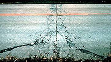
D-cracking in Portland Cement Concrete Pavement
Joint Sealer
Expansion joint sealer must be a 705.04 hot-applied joint sealer conforming to ASTM D 6690, Type II.
Curing materials
705.05, 705.06, 705.07 Type 2
These curing materials are burlap cloth, sheet-curing materials, and liquid membrane-forming compounds. The liquid membrane-forming compounds used on the project must be on the Department’s Qualified Products List.
Tie Bar Steel,
Epoxy Coated
Tie bar steel used in the longitudinal joints in concrete pavement must meet the epoxy coated reinforcing steel requirements of 709.00.
Reinforcing Steel
The steel reinforcing steel must comply with 709.09, 709.10, and 709.12
Dowel Bars and
Basket Assemblies
Dowel bars and basket wires used to support the dowels at the proper position must be coated with a fusion-bonded epoxy coating conforming to AASHTO M 254 with the exceptions listed in 709.13.
Equipment
(451.03)
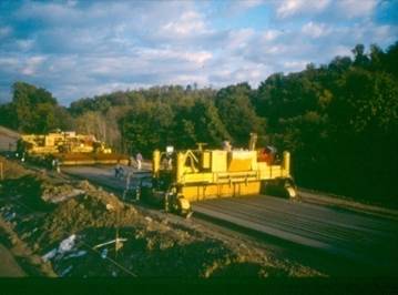
Reinforced Portland cement concrete pavement is placed by a series of equipment called a paving train. A paving train normally consists of a concrete spreading machine, a mesh cart, a mesh depressor, a finish paving machine, a work bridge and a cure/texture machine.
The riding qualities of a pavement depend largely on the proper operation of mechanical finishing equipment. The equipment must be in correct adjustment. It is almost impossible to use hand finishing to correct a poor surface left by the equipment. Frequent checking and minor adjustments to compensate for changing conditions, will do much to eliminate surface irregularities.
The Contractor is responsible for equipment adjustments. Department personnel are not expected to adjust or advise the Contractor on how to adjust and maintain mechanical equipment, but they are expected to observe the checking of all equipment. The Inspector should be able to recognize when such equipment is out of adjustment or is not coordinated with the balance of the paving train. The following information on spreaders and finishing equipment is given to provide some knowledge on the operation of the equipment.
General Equipment
Requirements
The equipment used must be self-propelled spreading and finishing machines that are capable of consolidating and finishing the concrete; and producing a finished surface meeting the requirements specified. The specifications give the Contractor the option of using slip-form or fixed-form pavement construction methods.
Vibrators are used for the full width and depth of the concrete slabs to provide consolidation of the fresh concrete. They must be internal type, using a tube or multiple spuds. Internal means the vibrators must be immersed in the fresh concrete. External vibration is not allowed. Vibrators may be attached to the spreader or the finishing machine; or may be mounted on a separate carriage. They must not come in contact with the joint load transfer devices, subgrade, reinforcing mesh or side forms. Multiple spuds should not be spaced further apart than 2 1/2 feet (0.76 m). Therefore, a minimum of 10 spuds is required for a full 24 feet (7.2 meter) width paving.
Internal vibrators must operate at frequency of 7,000 to 11,000 impulses per minute. The vibrators should be connected to an electronic monitoring device equipped with an automatic recorder. The monitoring device should display the operating frequency of each internal vibrator. The readout display should be located near the paving operator’s controls and must operate continuously when paving and display all vibrator frequencies with manual or automatic sequencing between individual vibrators. The automatic recorder must record the following information each 25 feet (8 m) of paving or every 5-minute time interval:
· the time of day
· station location
· paving machine track speed
· the frequency of each vibrator
If the monitoring system is not equipped with an automatic recorder, the contractor must manually record the above information every 30 minutes. The Contractor must provide a record of the data to the Engineer each paving day.
Vibration is required for all concrete pavements. Small irregular areas require vibration by hand-held or machine-mounted equipment to assure that adequate consolidation for the full depth and width is achieved without segregation.
Vibrators must be connected such that they turn off when the machine on which they are mounted stops.
Transit Mix and
Central Mix Equipment
Concrete plants and hauling units must be checked for proper condition prior to paving operations, and at regular intervals during paving. Water and admixture metering devices should be checked to assure proper calibration within specified tolerances.
Transit Mix Trucks used for Concrete Delivery
Transit mixers should be checked to determine that the counters are functioning properly. After having been mixed for not less than 70 revolutions at mixing speed, the mixer should contain concrete of uniform consistency and be able to discharge the batch without segregation. Since this determines acceptability, mixers that do not perform in this manner should not be used, and discontinued if encountered. Sources of trouble are badly-worn mixing blades and leaky valves which prevent mixers from producing uniform concrete. They should not be used until corrected.
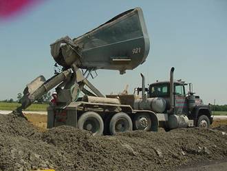
Non-Agitation Concrete Delivery Units - Dump-Crete Truck
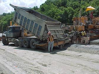
Non-Agitation Concrete Delivery Units Dump Truck
Central mix plants should be checked to see that the mixer drum is capable of uniformly mixing and discharging the large volume of concrete. During paving, the Contractor or ready mix supplier must keep mixer blades free from concrete build up and excessive wear.
When the concrete is transported to the paving site in dump trucks or other non-agitating units, check the bodies to see that they are water-tight and free of objectionable corners or internal ribs where concrete may accumulate. Canvas covers to shield concrete from sun and wind shall be provided when required by the Engineer.
Concrete Batch
Plants
Aggregate stockpiles should be placed on areas which are paved, prepared by using sheet metal, wood plank, etc., or they may be placed directly on the ground. When building stockpiles on existing ground, the area should be firm, cleaned of foreign material, and shaped to provide drainage. No aggregate is to be removed from the stockpile within one foot of the ground until the final clean up. Aggregate within this area should be processed to meet specifications before permitting its use.
Stockpiles should be built in such a manner that different types or sizes of aggregate do not become mixed and the aggregate does not become segregated.
In building the stockpiles of coarse aggregate, exercise continual care to prevent segregation through improper handling. A clam bucket operated by a crane of sufficient size so that the center of the pile can be reached from the edge is best for this work. In depositing the aggregate, the bucket should be lowered close to the level where the aggregate is to be deposited before releasing the aggregate. This prevents the larger aggregate from rolling to the bottom of the pile causing segregation. As the pile increases in height, each layer of aggregate should be benched back to form tiers that will help limit rolling and segregation.
Other equipment may be used in conjunction with a clam bucket. If the Contractor uses front-end loaders to build the pile, they must have clean rubber tires. As with the clam bucket, the drop should be as short as possible when depositing the aggregate. Once on the pile, the front-end loader should not be permitted to move on and off of the pile as this may cause contamination.
Pushing of large aggregate with a bulldozer is not permitted, as this causes segregation. Use of steel treads on the pile is not permitted as they tend to crush the aggregate.
Small aggregate does not segregate as easily as large aggregate because the smaller pieces are less likely to roll down the side of the pile.
Any operation which might result in segregation, degradation, or contamination is not permitted. When these conditions appear evident, run a gradation test and, if substantiated, adjust the operation.
Materials should be placed in the batch plant bins by dumping into the middle of the bin with as short of a drop as possible. Keeping the drop to a minimum reduces the chance for segregation in handling aggregate, as well as in handling concrete.
The Specifications require that concrete materials be measured by weight. The scales shall be checked for accuracy with standard test weights as outlined in Item 499.
Fixed Form
Construction (451.03.A)
This construction method requires that the Contractor furnish equipment that will spread, screed, and consolidate concrete using one or more machines operating on previously placed side forms. There must be enough equipment with capacity to perform the work at a rate equal to the concrete delivery rate. The equipment must uniformly distribute and consolidate the concrete without segregation.
The equipment must either operate on two side forms, on an adjacent lane and one side form, or on two adjacent lanes as necessary. When operating the equipment on adjacent lanes, the adjacent lanes must be protected from damage from the equipment.
Forms for use on ODOT projects must meet the following requirements:
· made of steel
· straight and must not be less than 10 feet (3 m ) in length
· have a depth equal to the pavement thickness specified
· have a horizontal joint and base width equal to the depth of the forms
· forms that are bent or damaged are not permitted
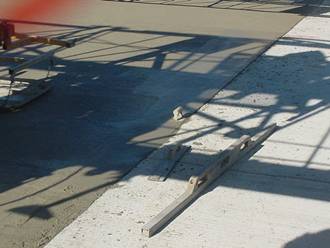
Sections of Steel Concrete Paving Forms
Fixed Forms in Place Ready for Paving
Forms must be cleaned and oiled each time they are used. If the radius of the pavement edge is 100 feet (30 m) or less, flexible or curved forms may be used as approved by the Engineer.
The Contractor must provide methods and devices that securely set forms and withstand paving equipment operation. Built up forms must not be used unless constructing less than 2,000 square yards (1,650 square meters) of pavement for the entire project. All forms must have adequate joint locks to tightly join the ends of abutting sections together.
Transverse
Finishing Machines for Fixed Form Construction
The transverse finishing machine should first be checked for its operating condition. The bearings, especially those of the cranks actuating the oscillating screeds, should fit snugly so that the screed reverses direction without slap (which would rack the forms).
The end plates that slide on the forms should be inspected for wear and reversed or replaced if necessary. The screed should be checked for straightness or crown if one is required. Perform this check by placing a block on the forms under each end of the screeds and stretching wires at both front and back across from form to form. Check the crown by measuring the offsets from the wire to the screed. Adjusting bolts can be loosened or tightened to secure proper adjustment.
The exact tilt required in each screed cannot be determined until construction begins. However, at the start of paving operations, the front edge of the forward screed should be titled about 3/16 inch (5mm) and the rear screed set level. Adjustments can be made readily by end bolts provided for this purpose.
Springs are used as shock absorbers to prevent slap at the end of the stroke. These should be checked to insure that they are in compression at all times. The screed lift chains must be long enough so that they are not tight at the end of the stroke; otherwise, the screed will be lifted off the forms at every oscillation.
Finally, the wheel scrapers should be tightened so that they will be sure to keep the wheels clean.
Operation of
Transverse Finishing Machine
The work of the transverse screed is an intermediate step in the process between placing and distribution of the concrete and the final mechanical finishing. The work performed by the screed should be as nearly complete as possible, so that smoothing and floating is the only operation required by any following equipment.
As the transverse screed begins work, the concrete before it must be distributed to approximately the correct surface level, either by mechanical concrete spreaders or by hand methods. The requirements for correct transverse screed operation are the same regardless of the method of prior distribution, except that local grading by hand work will be more irregular and will require more care in the screeding operation.
The transverse screed must leave the surface with a uniform texture and a uniform, correct elevation for final finishing. Good finish cannot be obtained if the screed does not perform this function. Deep or irregular corrugations behind the screed indicate improper operation.
Satisfactory results depend upon several critical factors. These factors must be considered at all times, and variations in the adjustments or in the operation of the screed must be made, as occasion demands, to keep the factors always in balance.
The head of concrete carried in front of the forward screed must be maintained at a uniform height, about 4 to 10 inches (100 to 250 mm), and in uniform quantity across the full width of the lane.
The concrete head carried in front of the rear screed must be uniform and about 2 to 4 inches (50 to 100 mm) high. The material being moved ahead by the rear screed should roll, not flow or tear, and the mix and timing of operations must be controlled to satisfy this requirement.
The height and tilt of the screeds must be adjusted to compact the particular mix being used and to permit a uniform amount of surge.
The traction speed, screed speed, and length of screed stroke are controlled independently. These must be combined in the proper relation to obtain optimum results. As conditions on the project vary, these relationships should be varied to produce a consistent surface.
The forms and wheels must be kept clean. If the wheels ride on an irregular surface, the concrete will show corresponding roughness. The screeds must be kept clean, so that they do not leave streaks in the concrete and do not drop lumps of hardened concrete on the fresh surface.
The amount of concrete being carried ahead of the screeds (both forward and rear) controls the amount of surge past the screeds for any given mix. If the head of concrete is too high, an excess will pass under the screed and leave an overload for following equipment. If there is a deficiency of concrete at any point in front of the screed, a low spot develops. If the head varies continually, the surge will also vary and a wavy or rough surface will be left. Therefore, a uniform roll of concrete must be maintained along the front edge of the screeds to provide a uniform amount of surge. At the beginning of a day’s work, a small amount of concrete should be placed in front of the forward screed to provide a working supply for filling in low areas. This accumulation should not be allowed to build up as the work progresses, but should be maintained uniformly. If excess builds up, the excess should be screeded off or a second pass made.
The Inspector should insist on coordination of distribution and transverse screeding to obtain continuous, acceptable results. The forward screed should compact the concrete level with the top of the form allowing for a very small amount of settlement that usually occurs before the following finisher passes. The difference in the requirements at the two screeds accounts for the difference in the size load each should carry.
Inspectors on transverse screeding work must remember that the finishing machine is not intended for heavy duty. The surface left by this work must be uniform and satisfactory. The transverse screed is capable of meeting these requirements. The Inspector should insist that the operator make full use of the machine’s capabilities in order to obtain a complete and proper integration with the entire paving process.
If one pass of the screed does not result in satisfactory surface conditions, a second pass is necessary. It is preferable that preceding operations be controlled so that a second pass is not required at intermittent points. The Contractor may elect to use two screeds or to pass over the entire area twice with one machine. Different amounts of screeding will result in variable surface conditions and are to be discouraged.
Screeds should be operated with the screed wearing plates working directly on the forms. A straight screed with no tilt results in a concrete surface at or below form level, except for surge. Adjustments in screed elevation and tilt may be required to work certain mixes properly. If the concrete mix is extremely stiff, the screeds normally will tear the surface and leave insufficient mortar for finishing. Under these conditions, the front or first screed should be tilted so that the forward edge is raised slightly. This compacts the concrete as the screed passes and forces a small amount of mortar to the surface. Extremely stiff mixes usually demonstrate an absence of surge which, with combined tearing, leaves the surface below the top of forms. The center of the screed then should be raised slightly by adjusting end screed hanger bolts, leaving the end plates to work on the forms with the remainder of the screed raised. This permits the required amount of concrete to pass the forward screed. The rear screed always should be straight along the rear edge and work directly on the forms.
The amount of tilt of the screeds must be worked out for the particular job conditions. As a starting guide, the following information will be of assistance. With standard Portland cements and with air-entrained concrete of relatively stiff consistency, less than 2-inch (50 mm) slump, the forward screed will likely require a tilt of 1/4 inch (6 mm) or less and the rear screed a tilt of 1/16 inch (0 to 2 mm).
The combination of traction speed and screed motion depends on the concrete mix and consistency, and on the grade or super elevation of the pavement. With stiff mixes, the screed speed should be rapid with a long stroke and the traction should be slow in comparison to more workable mixes. This aids in compaction and in providing enough mortar at the surface for finishing. With more fluid mixes, the screed action should be decreased; both in speed and length, and the traction speed should be increased. This will prevent over working or excessive agitation of the concrete, which might cause flowing to the low side of the forms, excessive surge past the screeds, or a pooling of wet mortar on the top. The relation of traction and screed speeds is very important. In most machines, the controls are independent and the proper combination can be made by trial without any difficulty. A change in speed of either screed or traction requires only shifting of a lever. The change of length of screed stroke requires a work stoppage and readjustment of the screed drive, but this change should not be required very often unless control of the concrete mix is poor. Poor control of the concrete mix should not be tolerated.
The screed wearing plates are rubbing continuously on the forms or on completed concrete lanes. They are made of abrasion-resisting steel, but may wear rapidly. As they wear, they have the effect of lowering the entire center portion of the screed by the amount of wear. Furthermore, the wear may not be the same for the full length of screed stroke, and may change the strike-off elevation of the screed. They should be checked at the beginning of each job. Adjustments for up to 1/8 inch (3 mm) in wear can be taken care of by adjusting the screed bolts. The plates should be replaced when wear exceeds this amount.
Exercise care when operating the finishing machine over expansion joints to avoid displacing or damaging the preformed expansion material. Any method of operation that does not interfere with the expansion material will be permitted.
Combination Float
Finisher
The combination float finisher is commonly used to provide the final mechanical finish on a pavement. The machine consists of two screeds and a float and is designed for use on a 24-foot (7.2 m) pavement.
The front screed of the machine is a conventional reciprocating screed that rides the forms. The rear screed and float, however, are suspended from an approximately 16 foot (4.9 m) beam platform and do not receive any support from the forms. The elevation of both the rear screed and the float is determined by adjustment of the hangers that connect them to the platform. As a result, variations in forms do not significantly affect the plane of operation of either the rear screed or float. The key to smooth finishing with this machine is the rear screed since it is the final screeding tool and operates from a 16 foot (4.9 m) straightedge essentially free from influence of deviations in the forms.
Spring-loaded shoes are fastened to both ends of the rear screed to keep the screed in contact with the forms. The springs are sufficiently strong so that the rails will be kept clean, but not so strong that they will cause the screed to raise when an undetected highpoint in the forms is being traversed.
The float does not oscillate but moves forward with the machine providing a smooth trowelled surface. It is approximately 30 inches (0.7 m) in length and rides on the slab between the forms. Both of the screeds and the float are provided with devices which permit rapid changes in crown. These devices make it possible to change crown at superelevated sections without delay.
Operation of
Combination Float Finisher
The combination float finisher serves both as a conventional transverse and longitudinal finisher. The transverse screeding is accomplished through the two screeds (front and rear) and the longitudinal finishing by the suspended finishing pan that rides on the slab surface.
Several details must be adhered to closely in order to obtain the best possible finish when the machine is used for the final mechanical finishing operations. These items are described in the following paragraphs.
The concrete must be accurately fed to the machine. Better results are obtained when spreaders and auxiliary screeds (when used), operating ahead of the machine, leave just enough concrete so that a uniform roll of 4 to 6 inches (100 to 150 mm) is carried on the front screed. When this condition does not exist, the equipment operating ahead of the float finisher should be adjusted so that such a concrete roll is obtained.
The screeds and float must be set accurately. Both front and rear screeds should be set flat. When the front screed is flat and carries a 4 to 6 inch (100 to 150 mm) roll, it passes sufficient concrete to form about a 2-inch (50 mm) roll on the rear screed. When this 2-inch (50 mm) roll reduces in size, fresh material should be carried back and placed to obtain a uniform roll. It is essential to keep the roll in front of the rear screed uniform for optimum results.
The rear screed cuts off any excess concrete and leaves the pavement surface at the desired crown and grade. When set to proper crown without tilt, the float just makes contact with the surface and trowels it smooth and free of screed marks. Occasionally, it is desirable to leave the front of the float about 1/16 inch (2 mm) high when greater compaction is desirable. This practice, however, generally leaves deeper transverse marks than are considered desirable.
The finishing machine is designed primarily for a one-pass operation. If all operations prior to the pass of the machine are as they should be, it is rarely necessary to make more than one finishing pass. If the forward speed is adjusted properly, the machine moves forward at a uniform rate, eliminating frequent stops that cause variations in the surface. It is true with this machine, as with other types of finishing equipment, that continuous operation provides smoother pavement.
The machine must be kept clean. The bottoms of the screeds and the pan must be absolutely smooth. Accumulations of hardened concrete (or oil and grease) that might drop on the pavement must be cleaned off continually. The machine should be cleaned thoroughly every day.
Slip Form
Construction (451.03.B)
This method of construction permits pavement placement without the use of fixed side forms. In lieu of forms, the paving machine vibrates, tamps, compresses, and strikes off the concrete within the machine’s moving forms, and extrudes the consolidated concrete slab. Consolidation is such that the vertical sides of the slab retain their shape and position after leaving the paving machine. Trailing side forms are needed only to protect the slab edges during hand straight-edging operations. The slip form paver/finishing machine has three main components: augers, vibrators, and a profile pan. The augers spread the concrete across the width of the area to be paved. The vibrators provide consolidation of the concrete as it passes under the paver. The profile pan, located at the rear of the paver, trims the concrete to the proper elevation and provides a smooth surface.
The base must be constructed as outlined in the specifications. Stability of the base is critical for slip form construction. The base must be graded to the plan elevation by a properly designed machine. The track area for the paving train may be brought to grade using a form grader, with a subgrader on crawlers used to grade the area under the pavement. An automatic subgrader operating from a preset grade line is ideal for slip form construction and does not require the use of a form grader.
Stabilization in the paving machine track area to provide traction is permissible, provided the area is scarified after pavement construction, to avoid interference with lateral drainage of the subbase. Any method of stabilization proposed by the Contractor must be approved by the Engineer.
An approved slip form paving machine or combination of paving machines must be used to spread, consolidate, screed, and finish the concrete in one pass. The machine(s) must consolidate the full width and depth of pavement being placed, to provide a dense homogeneous pavement slab, requiring a minimum of hand finishing. Two machines may be used with the leading machine striking off the bottom course for placement of the mesh. The width of the bottom course may be 6 inches (150 mm) narrower than plan width so as not to interfere with the second paving machine.
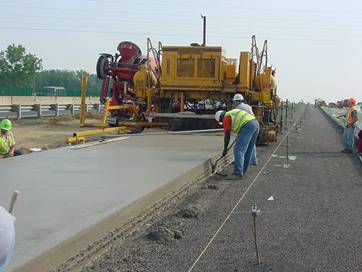
Slip Form Construction
Preset grade lines are required for slip form paving equipment to assure acceptable riding quality of the pavement. Paving equipment must have controls that trace the grade line and automatically adjust the screeds. String lines offset from and parallel with the edge of pavement are used most often. Sensors on the paver follow the string line and automatically adjust the screed.
The use of string lines will not assure riding quality. All lines, grades, and controls should be frequently checked to avoid obvious errors. The electronic controls of the slip form paving equipment are not capable of sensing grading errors and will therefore duplicate those errors in the pavement surface. When a string line is used, the string line should be supported at intervals that eliminate sagging of the string under its own weight. Supports every 25 feet (8 m) produce the most desirable results. In addition to the intervals between supports, the stringline tension must also be taut enough that excessive sag does not occur.
The concrete slump should not exceed 3 inches (75 mm) and the nominal range is 1 to 3 inches per 499. If the slump exceeds 3 inches (75 mm), the edges may be subject to settlement after the forms have passed. Slump less than about 1-1/2 inches (40 mm) may result in an open textured surface requiring excessive hand finishing. Therefore, the slump should be maintained between 1-1/2 and 3 inches (40 and 75 mm) for best results.
Good construction results are achieved by operating the paving machine with a continuous forward motion with a minimum of starting and stopping. When the paving machine stops, all vibrating, tamping and oscillating elements must stop also.
The slip form machine must not be used like a dozer to push large quantities of concrete piles out in front of it. Therefore, some means of depositing and striking off the concrete must be used to permit smooth uninterrupted operation of the paving machine(s). The use of spreader boxes, a concrete spreader, or any technique that provides a uniform distribution of concrete is permissible.
At the end of the day’s production, pavement at construction joints may be reduced approximately 2 inches (50 mm) in overall width. This allows the Contractor to use an insert just inside each moving side form so that the paving machine(s) can be positioned at the joint when production is resumed. The trailing side forms do not bind and spall the slab edges when this leeway is provided on each side.
Inspection of slip form paving should include checking the pavement edges. Since no forms are used to screed against or to hold the edge in place, the edge can slump downward or tilt out. A straightedge can be placed perpendicular to the edge to check transversely. In addition, the straightedge can be placed longitudinally at the pavement edge to check in that direction. Areas that do not meet the tolerance must be corrected while the concrete is plastic.
Where pavement will be placed against an edge, the pavement must not vary more than 1/4 inch (6 mm) below the typical section.
Where pavement will not be placed against an edge ( outside edge) the pavement must not vary more than 1/2 inch (13 mm) from the typical section.
All pavement edges must be nearly vertical with no projections or keyways exceeding 1/2 inch (13 mm). If edge projections exceed 1/2 inch (13 mm) concrete must be removed by hand methods and the edge should be troweled smooth.
Setting Forms
Forms are a potential source of trouble because they serve as the “tracks” for the paving equipment in addition to serving as forms for the concrete. Since developments in paving equipment have provided heavier equipment, the forms play an increasingly important role in the construction of smooth pavements.
Before any forms are set on a project, they must be inspected to see that they comply with specification requirements. In addition, they must have sufficient pin pockets for setting securely so that they will withstand the operation of the paving equipment. Forms are to be set such that that they do not vary more than 1/8 inch in 10 feet (3 mm in 3 m) on the top face; or more than 1/4 inch in 10 feet (6 mm in 3 m) on the vertical face. If they cannot be reset or repaired to meet this tolerance they cannot be used. Forms are reused continuously. Therefore, inspection of forms must be continuous. Any time forms are found out of tolerance, they must be rejected. Forms that are rejected should be marked so they are not incorporated into the work.
Forms are Set in Position and Pinned to the Base
Forms are to be set true to line and grade on a thoroughly compacted base with uniform bearing throughout their entire length and width. Using loose earth pebbles or other shims to bring forms to the required grade is not permitted. Whenever adequate and uniform form support is not obtained, the forms must be removed, the base corrected and compacted, and the forms reset. At least 3 form pins are to be used in each 10-foot (3-meter) length. These pins must be long enough to hold the form in position during the placing and finishing operations.
Pin keys must be straight and free-moving in the pockets and capable of holding the forms tight against the pins. The joint locks must not be bent or worn and must be capable of holding the ends of the forms in true alignment. The pins and locks are checked when the forms are set but should be rechecked just prior to placing of concrete and tightened if necessary. Make a final visual check at the same time to insure forms are at proper line and grade. Smooth riding pavement with good surface finish is extremely difficult to obtain with poorly aligned and set forms.
The forms are to be cleaned and oiled prior to placing of the concrete. When hook bolts or wiggle bolts are fastened to the forms, the forms must be oiled prior to placing of these units.
Fine
Grading of Subgrade or Subbase (451.05 A and B)
After the embankment has been placed and compacted the subgrade is brought to the required grade, cross section, and density in accordance with 204. Base material is provided by plan for all concrete pavements with only a few exceptions. The typical plan section indicates the depth and width of compacted base materials. Generally base material is 304 Aggregate Base and must be placed, shaped, and compacted in accordance with that specification. Fine grading of the base material should be done in advance of the concrete paving operation to allow the Engineer to check the established grade for conformance to the plan elevation. After the grade has been checked and accepted, no further disturbance of the base material is allowed.
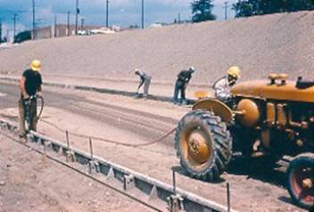
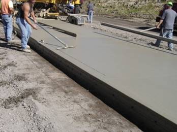
Fixed Form
Construction and Slip Form Construction
The surface of the base material is left approximately 1 inch (25 mm) above grade after compaction has been completed to the required density. Then, after forms have been set to grade for form paving or the string line is set for slip form construction, the slight excess is removed with a subgrade planer (subgrader). The fine grading operation should result in a slight removal so that the trimmed surface is compacted thoroughly without low areas. Low areas require the addition of material, compacting, and regrading resulting in a delay in progress of fine grading.
When automatic subgraders are used, they will precede the setting of forms. Grade will be maintained from a preset string line that will be parallel to the grade line. After final trimming the surface will be treated the same as for conventionally graded base.
Loose base material windrowed along the inside of the forms cannot be removed by machine so removal of this material by use of a shovel is necessary. This shall be done before re-compacting.
The trimmed surface left by the subgrader should be compacted to restore surface density. This rolling operation also smoothes the surface and reduces the friction between the base and the pavement.
For fine grading between forms the resulting base surface must be checked using a multiple pin template operated on the forms. The template must be operated behind the subgrader and roller. Any high or low spots encountered shall be corrected immediately, then rerolled and rechecked before continuing. Where the subgrader is operated on a string line, the grade will be checked based on the grade stakes for the pavement. The Inspector should record the limiting stations of the area checked and conformance to the specification requirements in project records.
The subgrader is usually one of the heaviest pieces of equipment operating on the forms. Therefore, this is an opportune time for the Inspector to observe the forms for excess movement or displacement. Areas where movement or displacement is noticed should be rechecked for compliance with requirements before placing concrete.
Moisture is controlled by spraying the base prior to fine grading, preferably in the late afternoon of the day before fine grading. This provides the uniform moisture distribution necessary for density. After removal of excess material during fine grading, moisture is present for the final surface compaction.
It is good practice to recheck the alignment and grade of forms, the form locks, and the pin keys after fine grading. Some Contractors assign employees to this job. The Inspector should check these items regardless of the Contractor’s operation to assure that any irregularities have been corrected. Since the paving equipment relies on the forms for support, it cannot be expected to produce a quality-riding surface when yielding or improperly set forms are encountered.
Placing Concrete (451.06)
Prior to placing concrete, the subbase must be thoroughly moistened with water. This keeps the subbase material from absorbing water from the plastic concrete affecting its workability and decreasing its set up time. Different moisture levels throughout the depth of concrete can build in stresses that lead to cracking.
The concrete must be placed as close to the paving and finishing operation as possible to limit rehandling. Excessive handling of plastic concrete can reduce the air entrainment and thus long term durability of the pavement.
Even distribution of concrete on the base, or in each course being placed, is the first step toward an acceptable job. The most even distribution in initial placing results in minimum variation in final surface settlement. If concrete is deposited in piles, or windrows, unequal consolidation may take place before finishing operation are begun. This never will be overcome throughout the finishing procedure and can be the cause of unequal settlement and rough surfaces after finishing has been completed. In the case of transmit mixer or dump truck delivery, use discharging methods that spread each batch as evenly as possible. Better results are obtained when a hopper-type spreader is used with either transit mixer or dump truck delivery.
Workers should not walk in the concrete unless they are wearing clean boots that do not have dirt, earth, clumps, or other foreign matter on them.
Concrete must not be allowed to displace dowel bar assemblies or expansion joints.
A separate concrete spreader is required when the width of
pavement being placed in one operation is 12 feet (3.6 meters) or more and the
area of any given width exceeds 10,000 square yards (8,300 square
meters). Concrete spreaders must be separate, standard
manufacture, self-propelled machines that receives concrete into a hopper
adjacent to the area to be paved and delivers the concrete in front of the
slipform paver and uniformly spreads the concrete at the proper thickness for
the full width being paved. Spreaders
must be adjusted to leave the proper amount of concrete for the required slab
thickness. The amount of concrete
left is determined by the elevation of a strike-off plate located behind the
screw augers, paddle, or hopper that distributes the concrete.
Concrete Spreader
The elevation of the bottom of the strike-off plate in relation to the top of the forms is shown on an indicator that is visible to the operator. The equipment should be checked to make sure that the indicator shows zero when the bottom of the strike-off is exactly even with the top of the forms.
Concrete spreaders are powerful pieces of equipment that will handle heavy accumulations of concrete. However, this is not a reason to permit improper distribution. When a slipform paver is equipped with a dowel bar inserter the separate spreader requirement may be waived provided the slipform paver is capable of spreading, consolidating, screeding, and float finishing the freshly placed concrete. The contractor should provide the Engineer documentation that the slipform paver will meet this specification.
The initial placing of the concrete should be just enough so that a slight excess is carried ahead of the spreader as it levels the concrete to a uniform surface. (If a spreader is not required, the concrete can be spread and leveled easily with shovels.) Unless this is done there will be an irregular surge past the strike-off of the spreader or past the finishing screed. This necessitates excessive manipulation of the surface in order to obtain specified smoothness requirements. Excessive manipulation tends to alter the quality, durability, and wear resistance of the finished pavement.
Concrete should not be mixed, placed or finished after dark without operating an adequate and approved lighting system.
When the air temperature is 35 °F (2 °C) or below, the concrete temperature must be between 50 and 80 °F (10 and 27 °C) at the point of placement.
When the air temperature is greater than 35 °F (2 °C), the concrete temperature cannot exceed 90 °F (32 °C).
Concrete cannot be placed on any surface that is frozen or has frost.
Two test beams are to be made for each 7500 square yards of concrete, or fraction of 7500 square yards that is placed each day.
Concrete Running
Yield Check
The running yield of concrete may be determined at any time during concrete paving and can provide an easy, accurate method of checking that the proper thickness is being placed. When a constant width and thickness is placed a running yield factor in cubic yards per foot (cubic meters per meter) can be calculated. This factor is determined by calculating the amount of concrete required for one foot length (one meter) of finished pavement of the width and depth being placed. This factor is computed by using Equations 451.2 and 451.3:
Yield Factor = Width (ft) x Thickness (ft) x 1 ft
27 ft3 / yd3
Equation 451.2 – Yield Factor
Yield Factor = Width (m) x Thickness (mm) x 1 m
1000 mm / m
Equation 451.3 – Yield Factor (metric)
Example:
A contractor is placing a 24-foot wide slab that is 9 inches thick. Determine the yield factor for this cross-section. Using Equation 451.2 the following calculation results:
Yield Factor = 24 ft x (9 in/12 in/ft) x 1 ft = 0.667 yd3 per foot of length
27 ft3/yd3
Once the running yield factor has been calculated, it can be used to determine the concrete volume required for any length of slab of the same dimensions. The running yield is determined by multiplying the running yield factor by the length placed as shown in Equation 451.4.
Running Yield = (Yield Factor) x Length Placed
Equation 451.4 - Running Yield
The actual quantity used is easily computed for any length of slab by multiplying the number of batches placed by the number of cubic yards (cubic meters) per batch.
Example:
Using the yield factor determined above calculate the running yield for 4,245 linear feet of concrete pavement when 360, 8-cubic yard truckloads were used. Also determine the volume used and compare the volume used to the volume required and show which is greater. Determine the difference in volume and the percent over-run or under-run.
Running Yield = (0.667 yd³/linear ft) X (4,245 linear feet)
= 2,830 yd³ (required volume)
Volume Used = (360 batches) X (8 yd³ per truck) = 2,880 yd³
2,880 yd³ (volume used) > 2,830 yd³ (volume required)
2,880 yd³ - 2,830 yd³ = + 50 yd³ difference
(50 yd³ ÷ 2,830 yd³) x 100 % = 1.77% overrun
The quantity used may be from 1 to 3 percent greater than that required, generally due to wasting over the forms, spillage, etc. An overrun of 3% or more should be investigated to determine the cause. Overruns may be caused by several factors, including inaccurate weighing, low subgrade/base, excessive waste, etc. Similarly, an under run in concrete may be due to inaccurate weighing, high subgrade/base, insufficient width, thickness of slab, settlement of forms, etc.
Hot Weather
Construction
When high air temperatures, low humidity, and winds are encountered during concreting operations the rate that concrete hydrates (hardens) increases. High temperatures, especially when accompanied by wind and low humidity, tend to cause a rapid loss of moisture from the surface of the pavement resulting in early setting and a reduction in time allowed for finishing.
Lowering the concrete temperature to 75º F (24º C) or below will help offset the effects of high ambient temperatures. Selection of a cool water supply is the most effective means of lowering the mix temperature. Sprinkling of coarse aggregate stockpiles for moisture control also aids in controlling the mix temperature.
It is a good practice when form paving, to maintain the slump of the concrete near the top limit during hot weather. Increasing the slump will help delay hydration, thereby making more time available for the finishing operations.
During hot weather operations there may be a tendency to add water to the surface of the concrete to aid in finishing. This practice cannot be allowed. Using water on the surface during finishing results in an increase in the water-cement ratio and washes out the entrained air in the concrete at the surface. Both of these changes adversely affect the long term durability of the surface of the pavement. The use of the whitewash brush to sprinkle water has probably been the cause of the majority of scaling occurring in concrete surfaces.
Under extreme drying conditions caused by high temperatures coupled with low humidity and high winds, mixing water may evaporate quickly from the surface of the concrete. This water may be restored by applying a fog spray of water on the surface, provided the surface has been completely finished and will not be screeded or straightedged. This provision should be controlled carefully and should be the exception rather than the rule.
An approved Type B or D (705.12) set retarding admixture is required when the concrete temperature exceeds 75°F. Set retarders help slow down the setting time thereby providing more time for finishing. The use of this admixture will result in less slump loss and result in higher strength concrete.
Protection from
Rain
Concrete paving must not be undertaken in rainy conditions, however in the course of paving, rain can occur and the Contractor must take steps to protect the plastic concrete from damage. If the pavement is adequately protected from rain extensive corrective work can be avoided.
A roll of polyethylene sheeting on the finishing machine or the curing machine can be quickly unrolled to protect large areas of pavement. When the concrete has not been protected and has been damaged by rain, increased attention to corrective measures will be necessary to obtain durable concrete.
Concrete that has been exposed to rain will have some mortar or paste washed from the surface resulting in a “sandy” appearance along with a speckled or splattered surface pattern. If the surface has not been machine finished, it should be screeded with the machine. This screeding will eliminate the sandy texture and force grout to the surface. For a surface which has been machine finished, the machine may be used to make a single pass over the area affected, or the surface may be dragged with the burlap to remove the sand and work grout to the surface. A broom drag may have to be used for several passes to restore the surface finish. When correcting damage to newly placed concrete surfaces, the excess surface water must first be removed; NOT worked into the concrete. Cement must not be placed on the surface in an attempt to restore cement paste washed away by the rain. Such a practice is detrimental to the concrete and must not be allowed.
When a rain persists for a lengthy period, it will be necessary to remove any protective covering to finish and texture the concrete before it sets. Membrane curing should not be applied when the surface is wet and may be delayed until paving is resumed. If polyethylene sheeting is used as a covering, curing may be delayed indefinitely provided the sheeting is maintained in accordance with the specifications. However, membrane curing should eventually be applied to provide a surface uniform in appearance.
If rain damages the curing membrane, the surface should be re-sprayed after the excess water has dissipated to restore the impervious covering and retain moisture necessary for curing.
If, for any reason, measures taken by the Contractor to produce a surface that meets specifications are unsuccessful, the affected portions of the pavement must be repaired or replaced to comply with contract requirements.
Cold Weather
Construction
During cold weather, provisions must be made to prevent concrete from freezing until it has attained adequate strength. Concrete that has been frozen prior to gaining sufficient strength may be permanently damaged; and may never achieve the design strength. Therefore, it is necessary to protect the concrete from freezing temperatures during the cure period.
The temperature of the concrete and the surrounding air directly control the rate of hardening of the concrete. As the ambient temperature decreases, the rate of hardening decreases. The rate of hardening ceases at the freezing point. If the concrete is maintained just above freezing, it will not be damaged. However, it will require a lengthy curing period before it will harden and gain sufficient strength.
The Contractor is responsible for protecting concrete during cold weather. If damage might possibly occur, the surface shall be protected by any means that prevents the concrete from freezing and retains the heat of hydration.
In order to control the rate of hardening and strength gain, it may be necessary to control the temperature of the concrete being placed and to protect the concrete thereafter to retain the heat of hydration during curing. If the air temperature is 35º F (2º C) or below when concrete is being placed, the concrete must be have a temperature from 50º to 80º F (10º C to 27º C) when placed. The Contractor is responsible for ensuring that the concrete temperature is in the required range.
If the concrete temperature is less than 50° F the mixing water or aggregates may be heated. The heated water and aggregate should be introduced into the mixer before the cement, so that the temperature is reduced before cement is added to avoid the possibility of a flash set. One further precaution is to delay the introduction of the air-entraining agent until the temperature has been reduced, because hot water tends to reduce its effectiveness.
The subgrade or base and forms must be free from frost when concrete is placed. Covering these areas usually prevents frost and avoids delays.
Any request to incorporate an accelerating admixture during cold weather construction must be submitted and approved.
Job Control Testing
and Sampling
All material being used in the production of concrete shall be sampled, tested and approved, or accepted by certification before being used. Material that has not been sampled before delivery to the project must be sampled and submitted for testing. Such material must not be used until approval has been given by the Laboratory. Sampling must be done in accordance with the specifications and as outlined in Item 499.
Concrete for use in pavements must meet the specified requirements for air, slump and yield. Tests must be conducted to check for compliance with these requirements. The test results must be within the following limits:
|
AIR |
SLUMP |
YIELD |
|
6 ± 2% |
1 – 3 inches |
± 1% |
|
8 ± 2% when using No. 8 Course Aggregate |
4 – inches maximum |
The Contractor must be notified of out of specification test results and make immediate adjustments to the mix. Production should be stopped and check tests made to confirm noncompliance of the original tests. Concrete that does not meet specification requirements must not be used unless adjustments can be made to correct the deficiency prior to incorporating it into the work. The fact that concrete has been produced and transported to the project does not justify its use unless it conforms to requirements.
Insufficient air may be corrected by the addition of an air-entraining agent and remixing the load to generate additional entrained air. Variations in yield should not be cause for rejection; however, immediate adjustments must be made in the batch weights and must be followed by additional yield tests until conformance is obtained. Slump may be increased by the addition of water provided it remains within the limits of the water-cement ratio. If slump is excessive, the concrete should not be used.
Concrete cylinders are not required for pavement concrete. However, if for some reason cylinders are desired, they should be cast from concrete obtained at the paving site and are to be made in accordance with Item 499. Cylinders are to be shipped to the Laboratory on the fourth day after casting where they are tested for compressive strength at 28 days of age.
Results of air, slump, and yield tests must be recorded on the Concrete Inspector’s Daily Report. Results of flexural tests on beams are to be recorded in the project records. Results of compression tests on cylinders (if made) will be reported by the Laboratory.
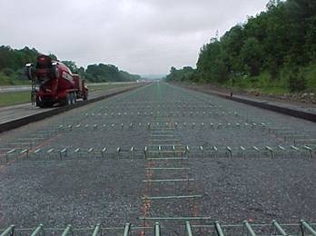
Placing Reinforcement (451.07)
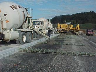
Distributed steel or reinforcement used in reinforced pavement (Item 451) is generally welded wire fabric or mesh. Its principal function is to hold together the fractured faces or slabs after cracks have formed. Adequate load transmission across the crack is thus assured, and the infiltration of incompressible material into the crack is prevented or delayed. It does not increase the flexural strength of an unbroken slab. Like tiebars, steel mesh is designed to withstand tensile stresses and hold the slab together.
Mesh is usually delivered to the job in advance of paving operations and stored. It should be carefully stacked and kept clean. Before it is used, it should be inspected to see that it has not been damaged in shipment or in storage, and that it is free from dirt, oil, and mud, which will hinder the bond with the concrete. Any mesh that has been bent or has broken welds should be rejected. If the mesh is repaired, it should be rechecked before using. Mesh with rust, mill scale, or a combination of both will be considered satisfactory provided the minimum dimensions are not less than specified. Recent research indicates that tight, scaly, and pitted rust does not prevent bond, but actually improves it.
Therefore, mesh should not be rejected for rusting unless the rust is so severe that the wire dimensions are reduced to less than the minimum specified. Reinforcing mesh details for (Item 451) pavement are shown on Standard Construction Drawing BP-1.1. The longitudinal wire is designated as a W8.5 or D8.5 (MW55 or MD55) size and has a nominal diameter of 0.329 inch (8.4 mm). The longitudinal wires are to be spaced at 6 inch (150 mm) centers. A W4 or D4 (MW26 or MD26) wire is used transversely and has a nominal diameter of 0.225 inches (5.7 mm). Transverse wires are to be spaced at 12 inch (300 mm) centers. If it is suspected that the wire dimensions have been reduced, the District laboratory should be requested to check the wire dimensions with a micrometer.
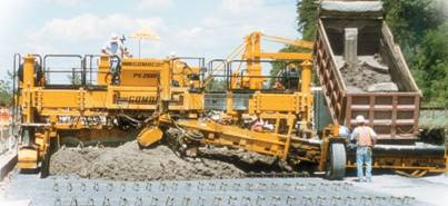
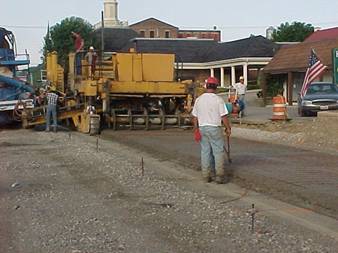
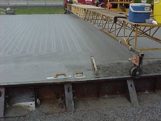
Concrete Spreader with a Mesh Cart
If mesh is placed along the rough grade or the shoulder to be easily accessible during paving, it should not be done so far in advance that mud will accumulate on it. Take care to prevent the mesh from becoming badly bent.
If a mesh cart is used on the forms behind a spreader, the mesh is stacked in cart-sized piles at intervals along the grade. These stacks should be placed on wood blocks or in some manner to keep them from becoming caked with mud or soil.
The specifications allow three methods of installing reinforcing mesh. The allowable methods are:
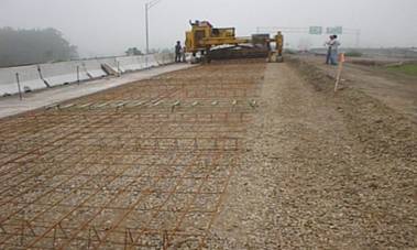
1. Place one layer of concrete, place the mesh on top of this layer so that it is located at its final location without any further manipulation, and place the second layer of concrete on top of the mesh. If the pavement is being placed in two layers, the concrete for the base layer should be distributed uniformly on the base and then struck off by means of a mechanical spreader to the proper depth. The strike off should leave a plane surface without voids or high or low spots on which to place the mesh
2. The mesh may be supported on chairs at the correct elevation and securely anchored to the base and the concrete placed in one layer.
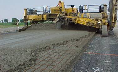
3. Place and spread one layer of concrete; while the concrete is still plastic, use a mesh depressor that vibrates or mechanically installs the mesh to the proper depth in the slab. This method eliminates the need for placing two courses of concrete and thereby eliminates the possibility of a plane of weakness (a cold joint) between two separately placed courses. Control of the mesh placement within the slab is more accurate than when placed between courses, based on measurements of cores removed for checking thickness requirements. Another advantage of this method is that a bulkhead can be placed readily and quickly in the event of breakdown since the concrete is placed full depth, and not in two separate courses.
Placing Two layers of Concrete
Mesh Supported on Chairs
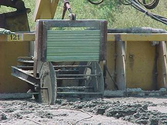
Using a Mesh Depressor
Mesh is required to be located in the slab within the range of 2 1/2 inches to T/3 + 1 inch (64 mm to T/3 + 25 mm) below the finished concrete surface (where T is the thickness of the pavement). In its final position, reinforcing mesh must not touch either dowel bars or tie bars. Mesh must also be located such that there is 2 inches (50 mm) clearance from a longitudinal joint or pavement edge to the reinforcing wires and 12 ± 2 inches (300 ± 50 mm) from any transverse joint.
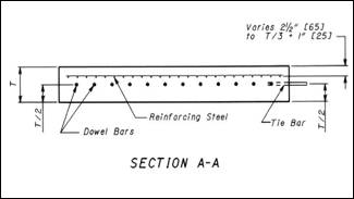
Location of Reinforcing Steel Mesh
If the mesh is bent, it should be straightened before it is placed; if it has a gradual bow, place it so the concave side is down. Workers placing steel must not track mud or dirt into the concrete.
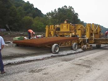
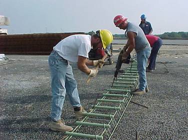
Two types of machines have been approved for use in vibrating the mesh into position. One type consists of a grid of steel plates approximately 15 feet (4.6 m) in length and extending the full width of pavement being placed. The self-propelled machine is positioned over the mesh, stopped, the mesh depressed into the freshly placed concrete, and moved ahead to repeat the operation.
Mesh Depressors
The other type is also self-propelled and consists of long tapered longitudinal runners across the width being placed. This machine gradually depresses the mesh into position in the fresh concrete using an oscillating tamping motion while continuously moving forward.
Since there is forward movement during placing, the latter type of machine may cause movement of the mesh across transverse contraction joints when not properly adjusted. When using a machine of this type, periodic checks must be made by uncovering the mesh at joint assemblies to assure that the specified clearance of 12 ± 2 inches (305 ± 51 mm) is being maintained on each side of the center of the transverse joint. If the mesh position is found to be outside of tolerance, it should be corrected and the machine adjusted at once; or its use immediately discontinued. Production may be continued without the mesh installer by changing to the two-course method.
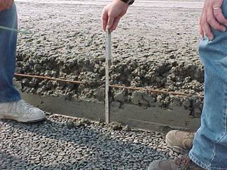
Both types of machines can be adjusted to control the depth of the mesh. Therefore, depth checks must be made daily to confirm that the machine is placing mesh to the required depth. Standard Construction Drawing BP-1.1 requires the mesh to be placed below the top surface of the pavement a distance of between 2 1/2 inches to T/3 + 1 inch (64 mm and T/3 plus 25 mm) where T is the thickness of the slab. When mesh depth is out of tolerance, immediate adjustments must be made by the Contractor.
The mesh is to be placed between the forms, or between the pavement edges, leaving 2 inches (50 mm) between the ends of the wires and the side forms, pavement edge, or pavement centerline. Reinforcing mesh is normally shipped in lengths of 19 feet (5.9 m) by 11 feet 8 inches (3.6 m) wide which will fit the specified joint spacing of 21 feet (6.5 m) for reinforced concrete pavement with an allowance of 12 ± 2 inches (300 ± 50 mm) from the center of each transverse joint. If shorter lengths are provided, transverse laps must be 12 inches (305 mm) and mesh sheets must be fastened at the edge of the lane and two other locations.
Usually, mesh is not fabricated for lane widths greater than 12 feet (3.6 m). Therefore, when placing pavement lanes in excess of 12 feet (3.6 m) in width it will be necessary to tie additional mesh to the standard width sheet. This is done by tying the outer longitudinal wire of adjacent sheets together. A minimum of four ties should be placed along the overlapped longitudinal wires to hold the two sections of mesh in the same plane until the concrete sets.
If the screeding operation has been done properly and the mesh placed in flat sheets and tied properly, there will be no difficulty with the steel working up into the finishing operations.
Joints (451.08)
Joints are classified as transverse and longitudinal. Transverse joints are further classified as contraction, expansion, and construction joints. Detailed instructions for joints are found in the specifications and in the standard construction drawings. See Standard Construction Drawing BP-2.1 for longitudinal joint details and BP-2.2 for transverse joint details. The Inspector should know the requirements of the specifications and the drawings before inspecting joint construction. All transverse joints are to be constructed normal to the centerline of the pavement lane unless otherwise noted on the construction plans.
Joint sawing is required to prevent uncontrolled cracking of concrete pavement and is required for all transverse contraction joints and for all longitudinal joints when concrete pavement has been placed between two lanes at the same time.
Joint openings are to be constructed in accordance with the requirements of the applicable standard construction drawings.
The timing of the sawing operation is critical. The use of HIPERPAV software is required to determine the sawing time limits to help protect from early uncontrolled cracking. The software is available as detailed in Supplement 1033 as well as the requirements for analysis. It must be noted that the use of HIPERPAV does not relieve the Contractor of his responsibilities under 451.16 regarding the repair of cracks in the completed pavement.
The HIPERPAV analyses must be run 24-hours prior to placing concrete and for every pour. The HIPERPAV files and printout must be provided to the Engineer. If HIPERPAV predicts early age slab cracking will occur, whether due to standard construction practices, joint sawing methods, mix design or curing, the contractor cannot start construction until modifications have been made to eliminate HIPERPAV’s predicted slab cracking.
If HIPERPAV predicts that joint sawing can exceed 24 hours, all joints must be cut by the 24th hour.
Sawing must be done after the concrete hardens sufficiently to support the sawing equipment and to avoid spalling and raveling. This operation cannot be tied to normal working shifts. A standby saw is required at the paving site in the event of breakdown or inability of one machine to maintain necessary progress.
Inspection should include random checking of each day’s sawing to assure the width and depth specified is achieved. Saw blades will wear with use so continued checks must be made. Since the timing of sawing is critical, inspectors assigned to this operation must be aware of the importance and document the actual time of sawing.
Sawing may be done wet or dry, and the cut must be cleaned by a jet of water (if sawed wet) or air under pressure (if sawed dry).
Longitudinal Joints
(451.08.A)
Joints between adjoining lanes of pavement or shoulders are longitudinal joints. They are necessary to control cracking in the longitudinal direction due to the warping stresses in wide concrete slabs. Joints between separately-placed adjoining lanes are longitudinal joints as well as construction joints. In general, the maximum pavement width used by the Department without a longitudinal joint is 16 feet (4.9 m) (for ramp pavements). Normal mainline pavements are 12 feet.
Epoxy coated tiebars or hook bolts are required at longitudinal joints to tie the lanes and prevent them from moving apart or from settling unevenly. Since they tie the lanes together by bond, tiebars or hook bolts are not to be oiled.
Longitudinal Joint
- (in simultaneously placed lanes)
Both tiebars and hook bolts should be placed in accordance with requirements of standard construction drawings called out in the plans. Tiebars are 5/8-inch (16 mm) diameter, deformed reinforcing bars, 30 inches (760 mm) in length. The spacing of tiebars or hook bolts varies with the pavement thickness. The maximum spacing of tiebars is 26 inches for pavement that is 10 inches (250 mm) thick or less, and 20 inches (508 mm) for pavement that is greater than 10 inches (250 mm) in thickness. Tiebars or hook bolts must be approximately at right angles to, and placed at 1/2 the thickness of the pavement. For example if the slab is 10 inches thick the tiebars are to be placed at 5 inches as measured from the surface of the slab.
Tiebars may be set on chairs prior to concrete placement; installed in the concrete after it is placed and spread; or may be inserted in the plastic concrete using a mechanical device on a slip form paver. Chaired tiebars must be adequately anchored to the base material. A mechanical inserter must be able to install the tiebars at mid-depth in the plastic concrete. Tiebars must be inserted after the concrete has been placed to its full depth and after the reinforcing mesh is placed (mesh is not required for 452 pavement). The tiebar inserter must be located in the paving train to assure consolidation of the concrete around the tiebars. Pushing tiebars into the plastic concrete by hand is not acceptable.
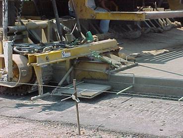
Mechanical Devices for Installing Tiebars in Longitudinal Joints between Lanes Placed Simultaneously – Wheel

Mechanical Devices for Installing Tiebars in Longitudinal Joints between Lanes Placed Simultaneously –Guillotine

Tiebars Can be Chaired at Longitudinal Joints Prior to Concrete Placement
When a standard (water-cooled diamond bladed) concrete saw is used to make the longitudinal joint between simultaneously placed lanes the following applies:
· Pavement ≤ 10 inches thick; saw the joint to a minimum depth of one-fourth the specified pavement thickness.
· Pavements > 10 inches (255 mm) thick; saw the joint to a minimum depth of one-third the specified pavement thickness.
· Saw joints 1/4 ± 1/16 inch (6 ± 1.6 mm) wide as measured at the time of sawing.
When using early-entry (dry cut, light weight) saws, only use saw blades and skid plates as recommended by the manufacturer. Perform the early entry sawing after initial set and before final set as follows:
· Saw the joint 2-1/4 to 2-1/2 inches (56 to 63 mm) deep.
· Saw joints approximately 1/8 inch (3 mm) wide as measured at the time of sawing.
Longitudinal Joint
- (between separately placed lanes)
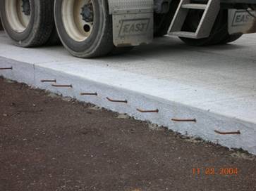
Standard 30-inch long tiebars can be installed in the slip formed edge of the pavement using a mechanical inserter at longitudinal joints when lanes are placed separately. This is normally done by a mechanical ram which pushes a tiebar 15 inches into the edge of the slab along the joint and at the center of the slab. Tiebars cannot be placed by hand. Bent tiebars are not permitted in longitudinal construction joints.
Mechanical Ram Inserts Tiebar in a Slip Formed Edge
Hook Bolts Screwed into Coupling at a Butt Joint
The epoxy coated hook bolt or an epoxy coated hook bolt alternate (wiggle bolt) may be used in longitudinal joints when using fixed form paving. An epoxy coated coupling attached to one half of the device is bolted to the side-form for the first lane placed. Before placing concrete in the adjoining lane, the other half is coupled to the embedded part after removal of the forms. The hook bolts are to be securely fastened to the forms so they are positioned properly in the slab. The right-angled hooks on each side of the coupling anchor provide the tie. The position of the hooks is not important, that is, they do not have to be turned down, up, or sideways.
The hook bolt alternate (wiggle bolt) with a coupling may be mechanically inserted into the plastic concrete through a hole in the side-form of a slip form paving machine. When this is done, the contractor normally uses a plastic cap in the threaded end of the coupling to keep concrete out of the threads. This plastic cap is removed once the concrete is set and a hook bolt is installed in the coupling.
The inside and outside edges of the paved lane must be edged to a 1/8-inch (3 mm) radius. The slab should be edged as soon as the concrete becomes stiff enough to remain firm without running back into the groove. The edge should be cut first with a small trowel and then followed by the edger. The edging tool should be held flat with the pavement surface. Tool marks left by the edging tool must be removed. Since the final texturing is to follow edging, this operation must not be permitted to lag.
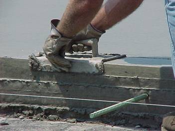
Tooling with a 1/8 inch Radius Edger
Tool Marks are Removed after Edging
Longitudinal joints between separately placed lanes are to be saw cut to a minimum depth of 1/2 inch (13 mm) and a minimum width of approximately 1/8 to 1/4 inch (6 mm).
Longitudinal joints between separately placed lanes require extra care to assure that a smooth transition from one lane to the other will result. Good workmanship is necessary at these joints to obtain satisfactory results. Hand finishing and straightedging should be performed carefully so that each lane will be at the same elevation. The surface of the pavement in the joint area should not vary more that 1/8 inch (3 mm) from a 10-foot (3.0 meter) straightedge in both longitudinal and transverse directions.
Tooling a Longitudinal Joint at a Butt Joint
Tooling the Edge when Fixed Form Paving Contraction Joints (451.08.D)
Load Transfer
Devices (451.08.B)
Contraction joints in concrete pavement are constructed at right angles across a pavement lane and are also called transverse joints. These joints control cracking of concrete pavement that result from stresses from volume changes during curing of the concrete. These joints are designed to transfer the loading from traffic from one slab to the next and require the use of dowel bars to accomplish this function. These dowel bars are called load transfer devices. Dowel bars can be pre-installed using dowel bar assemblies or can be installed using dowel bar inserters during slip form paving.
In contraction joints load transfer is achieved using round, straight, smooth, epoxy-coated steel dowels that are placed across the joint. Dowels must be placed at mid-depth, parallel to the slab and be 18 inches long. The required diameter of the dowel depends on the pavement thickness. The required dowel diameter is shown in Table 451.08-1 in the specifications and below (unless otherwise specified in the plan):
Table 451.08-1 Dowel Size
|
Thickness of Pavement (T) |
Diameter of Steel Dowels |
|
Less than 8 1/2 inches (215 mm) |
1 inch (25 mm) |
|
8 1/2 to 10 inches (215 to 255 mm) |
1 1/4 inches (32 mm) |
|
Over 10 inches (255 mm) |
1 1/2 inches (38 mm) or as in the plans |
Dowels must be spaced at 12-inch (300 mm) centers beginning 6 inches (150 mm) from the longitudinal joint. The spacing between the end dowel and the outside edge of the lane may be increased up to 12 inches (300 mm). A dowel must be placed 6 inches (150 mm) from the outer edge of the pavement when the spacing between the end dowel of the basket and the outside edge exceeds 12 inches (300 mm). Contraction joints are required to be spaced in the pavement at intervals not to exceed the maximum spacing indicated in Standard Construction Drawing BP-2.2 or the plan construction drawings. The maximum contraction joint spacing for reinforced concrete pavement (Item 451) is 21 feet (6.5 m). For non-reinforced concrete pavement (Item 452) and concrete base (Item 305) the maximum spacing is 15 feet (4.6 m).
To function properly dowels must be placed parallel to the surface and parallel to the centerline of the pavement since expansion and contraction movements occur in this direction.
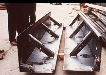
Dowel Basket
Assemblies
To assure proper alignment of dowels, a cage or basket is often used. This, together with the dowels, is called a dowel basket assembly. Dowel basket assembly wires as well as the dowels are required to be epoxy coated according to 709.13 of the CMS. Dowel basket assembly wires are to conform to Standard Construction Drawing BP-2.2.
Dowel basket assemblies are to be positioned not to exceed the maximum spacing for the type of pavement specified and must be perpendicular to the centerline and edge of proposed pavement or forms. Locating the transverse alignment may be by any method that assures a right angle to the centerline. On curves, the joints should be approximately on radial lines.
Transverse contraction joints must be continuous across the full width of pavement placed. Therefore, the line of a joint in a lane already placed must be continued in all other adjoining lanes.
Dowel Baskets are Pinned to the Base
When properly located and placed, dowel basket assemblies are anchored in place with steel pins. At least eight 1/2-inch (13 mm) diameter steel pins, 18 inches (460 mm) in length, are required to hold each 12-foot (3.6 m) basket assembly. The pins are driven at an angle to brace the assembly from lateral movement and to prevent vertical displacement when concrete is placed. Two of the pins are driven opposite each other at each end of the dowel assembly, and the remaining four are driven in a staggered pattern on each side. The assembly should not be hit when driving the anchor pins. If wires of the basket are bent, the dowels may be thrown out of line and require the entire assembly to be rejected unless it can be removed, straightened, and reset properly. Any badly distorted assembly should be rejected. The epoxy coating must not be damaged during the above operation.
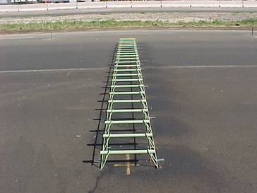
Clips with Power Driven Fasteners, Steel Pins or a Combination of the two are used on a Stabilized Base to Anchor Dowel Basket Assemblies
If concrete pavement is placed on an existing concrete pavement or stabilized base, the dowel baskets must be held firmly in position by use of power-driven fasteners and appropriate clips or pins driven in predrilled holes of a diameter slightly less than the pin diameter. The Contractor may use either of these methods or a combination of the two in sufficient numbers to adequately anchor the basket assembly. The method used must secure the dowel basket from lateral and vertical displacement during concrete placement.
If the dowel basket assembly is placed on a base consisting of sand, a minimum of 6 steel bearing plates approximately 5 inches (127 mm) square must be placed under each 12-foot (3.6 m) dowel assembly unit. Bearing plates also are required when any base material is used which permits distortion or settlement of the dowel assembly due to poor stability. One bearing plate is to be used with each of the four end anchor pins with the others spaced uniformly along the assembly. Shimming with pebbles, stones, etc. is not permitted. If shimming is necessary, it is obvious either that the base is not prepared properly or the dowel basket assembly is bent or misaligned. In either instance, the base or assembly must be rejected until corrective action has been completed.
Dowel Shipping and
Spacer Wires
After dowel assemblies have been set and anchored properly, the shipping and spacer wires used to hold both halves of the dowel basket together during shipping and handling must be removed. The shipping wire is normally cut at two locations and removed immediately prior to placing the concrete. The shipping and spacer wires are usually a small diameter wire parallel to the dowels and hooked or tack welded to the basket assembly wire. Shipping wires run the same direction that the dowels. Dowel basket assemblies must be anchored to the base before the shipping and spacer wires are removed.
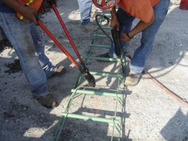
Shipping Wires are to be Removed after Baskets are Pinned
Checking Assemblies
Specifications require that dowel basket assemblies be preset prior at the beginning of paving unless the Engineer determines that it is impractical to do so. This allows time to spot check the baskets to assure they are parallel to the base and centerline of the pavement. Checking of the assemblies is to be done after the removal of the shipping and spacer wires. Spot measurement checks of the distance between the dowel and the forms (made at each end of the dowel) or the proposed edge of pavement provide a check for being parallel to centerline. The distance to each end of the dowel must be equal for the dowel to be parallel to the forms and the centerline. After some experience, this check can be a visual since dowels out of alignment stand out when observing them in relation to the forms.
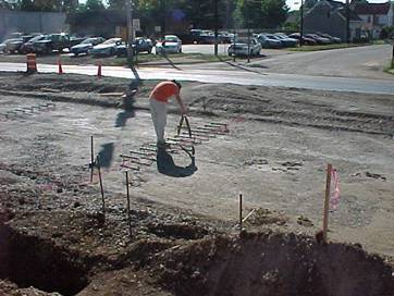
An A-Frame Level is used to Check that Dowels are Parallel to the Base
An adjustable A-frame level is used to spot-check several dowels in every assembly unit to assure that all dowels are parallel with the surface of the base. The level is first placed on the base adjacent to a basket assembly and adjusted to read level. Then the level is placed on the dowels. The bubble will indicate level if the dowel assembly is set properly and is parallel to the surface of the base. At least three dowels are to be checked in each 12-foot (3.6 m) section, one at each end and at the middle. If the dowels are not parallel with the surface when checked, the assembly must be adjusted and rechecked. If proper alignment cannot be obtained, the assembly must be removed and replaced.
Dowel Bar Inserter
Specifications allow dowels to be placed in the full thickness of the concrete pavement slab by a mechanical device called a dowel bar inserter (DBI) approved by the Engineer. It is intended to permit this method provided the Contractor is able continuously to install dowels properly.
A DBI is normally part of a finish paving machine and is located behind the vibrators and the initial strike-off of the slab. Immediately before inserting the dowels, they must be coated with a layer of new light form oil that serves as a bond-breaking material. Loose dowels are placed on an installing rack on the self-propelled paving machine directly above the pavement. These racks must be located to provide the correct dowel spacing in the joint. Once all dowels are in position in the rack above the slab, each dowel is pushed downward into the plastic concrete with vibration by two metal fingers which must push the dowel to the proper elevation. The metal fingers must insert each dowel so that it is parallel to the base and the pavement centerline and be at the center of the slab thickness. After the dowels are placed at mid-depth, the fingers are withdrawn leaving the dowels in position supported by the concrete. The dowels are to be installed after the concrete is placed to its full depth and after the mesh is positioned properly. The only operations permitted after positioning the dowels are machine’s final strike-off, mechanical float finishing, and hand finishing of the surface of the concrete. The use of a two-machine operation to insert and finish is not allowed.
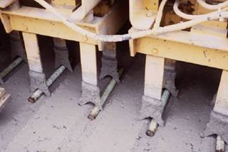
Concrete Paving Machine with a Dowel Bar Inserter (DBI)
As noted above; if a dowel bar inserter is used the requirement to use a separate concrete spreader may be waived by the Engineer provided the paving machine is capable of uniformly spreading the concrete. Since there are no basket assemblies set out in front of the paving machine with this method, the contractor can back up dump trucks or other hauling units directly in front the paving machine to discharge concrete.
In-place dowel alignment should be verified. A pachometer (cover meter), ground penetrating radar, magnetic tomography (MIT Scan), and, or coring can be used to verify the correct placement of inserted dowels as well as dowels in basket assemblies. When dowel bar inserters are used the correct installation should be verified for each production day. ODOT does not have a tolerance on dowel bar position in concrete pavement. Dowel locations should be in reasonably close conformity to 451/.08 which requires the dowel position be “parallel to the surface and centerline of the slab at mid-depth of the slab thickness”. Any questions regarding the correct installation of dowels should be directed to the Office of Construction Administration.

Pachometer
Preventing Bond to
Dowel Bars
For dowels to function properly in the concrete slab, they must be oiled with a thin coating of new light form oil for at least one-half their length to prevent the concrete from bonding to them. Most of the dowel assemblies have one end of the dowel welded to the basket wire. The free end, opposite the welded end, must be oiled. Dowels must be oiled within 2 hours of placing the concrete around them. Exercise care to see that the free end of the dowel is oiled. It is always better to oil more than half the length of each dowel to be certain that bond is prevented so that the joint will function properly.
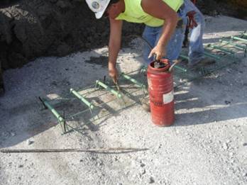
The Free Ends of all Dowels are to be Oiled within 2 Hours of Placing Concrete
Epoxy coated dowels should be inspected to assure the coating is continuous on the lateral surface of the dowel and that the coating is not perforated, cracked, or otherwise damaged, in which case it must be rejected. In addition, the coating must be free from holes, voids, contamination, cracks, and there shall not be more than two holes (pinholes not visually discernable) in any 12-inch (305 mm) length of the coated dowel. The free ends of the dowels must be free of burrs or projections.
Saw Cutting
When a standard (water cooled diamond bladed) concrete saw is used to cut the contraction joint the following applies:
· Pavement ≤ 10 inches thick, saw the joint to a minimum depth of one-fourth the specified pavement thickness.
· Pavements > 10 inches (255 mm) thick, saw the joint to a minimum depth of one-third the specified pavement thickness.
· Saw joints 1/4 ± 1/16 inch (6 ± 1.6 mm) wide as measured at the time of sawing.
When using early-entry (dry cut, light weight) saws, only use saw blades and skid plates as recommended by the manufacturer. Perform the early entry sawing after initial set and before final set as follows:
· Saw the joint 2-1/4 to 2-1/2 inches (56 to 63 mm) deep.
· Saw joints approximately 1/8 inch (3 mm) wide as measured at the time of sawing.
Joints should be spot checked to make sure that the contractor is sawing the pavement to the required depth.
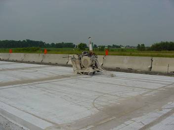
Standard Diamond Saw
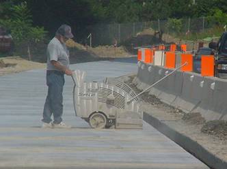
Lightweight Dry-cut Saw
If a crack appears ahead of the machine during pavement sawing, it is an indication that sawing is late. When such cracking is noted, stop sawing that joint immediately and move the saw ahead several joints. Saw a joint, move ahead several more joints, and saw another joint. Continue skipping three or four joints and sawing every fourth or fifth joint until sawing is back on schedule. The presence of slight raveling indicates proper timing of sawing. Saw every joint in order when sawing is back on schedule. After sawing has been completed for the day’s production the saw can be returned to saw the skipped joints. The standby saw may be put into service to saw the joints skipped if an experienced operator is available.
This procedure of skipping ahead and sawing every fourth or fifth joint relieves the stresses that occur when the concrete hardens and shrinks during curing. Once these stresses are relieved, the sawing of the in-between joints is not as critical but should be done as soon as possible.
The pavement is normally subjected to expansive forces the following day when the temperature rises. When temperatures drop during the evening of the following day, the pavement again experiences shrinkage stresses and all joints originally bypassed must be sawed before these stresses result in random cracking.
The HIPERPAV analysis for each pour should be utilized to predict the time for sawing as detailed in 451. 08. Generally pavement should be sawed the same day, usually six to eight hours after placing. Concrete placed late in the day may not harden to permit sawing until the next day, but sawing should be completed before the following late afternoon temperature change as shrinkage will again occur as temperatures drop. The Contractor is responsible for determining the optimal sawing time to prevent uncontrolled cracking.
Joints in lanes adjacent to previously-placed lanes that are tied together must be sawed as soon as possible to prevent uncontrolled cracking. If a new lane is tied to an existing concrete pavement, which is expanding and contracting with changes in temperature, stresses will be transmitted to the new slab unless joints are sawed as quickly as possible. The following provisions are important to obtain quality sawed joints in these areas:
· All transverse joints, except construction joints in the previously placed lane of pavement, must be in-line with those in the newly placed lane.
· The joint sawing must be done as soon as the saw can be operated on the newly placed pavement lane without damaging or excessive raveling of the joint.
· Full depth joint cracking in the previously placed lane indicate movement. Therefore, joints in the newly placed lane, which are in line with the cracked joints, must be sawed first.
· The cut is to be made from the old slab to the outside or open edge of the new slab being sawed.
A sudden drop in temperature, a wide range between day and night temperatures, or a cold rain creates additional problems when sawing contraction joints. These thermal changes add stresses and make the timing of sawing especially critical. When these conditions occur or are anticipated, increased attention to the sawing operation to assure control of cracking is needed.
Expansion Joints
(451.08.C)
Relief for compressive forces that are caused by movement in the pavement (typically in hot weather) is provided at bridges, structures, and at intersections in the form of expansion joints. Expansion joints permit contraction and expansion movement.
The first two regularly spaced joints in the concrete pavement adjacent to a bridge approach slab must be expansion joints (when a pressure relief joint is not included in the plans). Other expansion joints may also be detailed in the plans at locations at other structures and at intersections. Standard Construction Drawing, BP-2.2 provides additional information on the installation of expansion joints. All expansion joints are dowelled and allow the pavement to expand or grow due to temperature variations. A standard expansion joint allows for 1 inch (25 mm) of expansion.
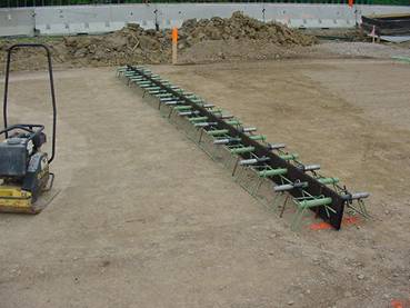
Typical Expansion Joint Basket Assembly
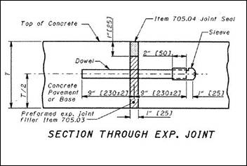
SCD BP-2.2 Detail of Section Through Expansion Joint
If the pavement consists of two or more separately placed lanes, the expansion joints must be a continuous straight line for the full width of the concrete pavement, including concrete shoulders. All expansion joints are perpendicular to the centerline adjacent to a skewed approach slab.
Preformed compressible material 1 inch (25 mm) thick is installed in a dowel assembly at the location of the expansion joint. It must be set perpendicular to the dowel as well as perpendicular to the line of forms and the pavement centerline. The material must extend down to the base and to the side forms to allow free movement throughout the entire joint. The top of the expansion material is held 1 inch (25 mm) below the pavement surface. It is permissible to place the expansion material closer to the pavement surface to facilitate sawing of this joint, provided all material is removed to a depth of 1 inch (25 mm). This area shall be sealed using a hot applied joint sealer meeting the requirements of 705.04.
Standard 18 inch (460 mm) long epoxy coated dowels are required for load transfer, in all expansion joints.
An expansion cap, also called a sleeve, is placed on the opposite ends of adjacent dowels (each dowel will have one cap but on alternate ends) to create a void in the concrete to permit expansion movement. The cap must be placed after the dowel has been oiled. The cap contains a crimp or stop that provides for the 1 inch (25 mm) void. These caps must not be forced beyond the crimp, otherwise, the space for expansion will be compromised and the joint will not function properly.
Inspectors must assure that the 1 inch (25 mm) thick preformed expansion joint filler is held rigidly in position and extends full width of all lanes. The preformed expansion joint filler must be the required height and must extend to the top of the base (or bottom of the new pavement) so that no concrete is permitted to flow under it. Holes in the expansion joint filler must be neatly punched or drilled, and the dowels must fit tightly through the holes with no gaps in which concrete could flow. The free end of each dowel (the end not welded to the basket wire) must be oiled with a bond breaker and the expansion cap/sleeve attached immediately prior to placing the concrete.
The Contractor must provide adequate consolidation throughout the slab depth adjacent to the preformed expansion joint filler and around dowels by use of hand-held internal vibrators. The top of the joint should be formed to a 1 inch (25 mm) wide and 1 inch (25 mm) deep opening, carefully edged using an edger having a 1/8 inch (3 mm) radius, on top of the preformed expansion joint filler and sealed with 705.04 joint sealers.
Construction Joints
(451.08.E)
Construction joints are transverse joints placed at the conclusion of each day’s paving or when production is interrupted for more than 30 minutes. These joints are formed by using an adequate bulkhead that provides a straight joint. Construction joints in all concrete pavements are to be dowelled and perpendicular to the centerline. Construction joints may be located at a contraction joint or between contraction joints. The bulkhead must have openings provided for individual dowels or a dowel basket assembly. The bulkhead must be shaped to conform to the typical section of the pavement.
Locate construction joints at or between contraction joints. If located between contraction joints, construct the construction joint no closer than 10 feet (3 m) to the last contraction joint.
In non-reinforced concrete base (305), construction joints must not be closer than 6 feet (1.8 m) to another transverse joint.
At skewed joints between approach slabs and approach pavement, exercise care to position the dowels parallel to the centerline. Recent experience indicates movement occurs at such joints. Make provisions for this movement by placing dowels the same as for contraction joints.
The joint may be hand-formed or sawed to the same dimensions required for transverse joints in adjoining pavement.
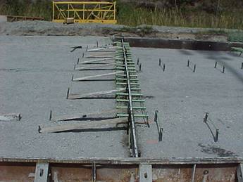
Transverse Construction Joints are Dowelled
Smooth epoxy-coated dowels must be used in construction joints placed parallel to the surface of the base. The dowel size and spacing is the same as required for standard contraction joints. See 451.08 B for those details.
Finishing (451.09)
Finishing behind the concrete paving operation can be done by a variety of methods. In all cases a 10 foot straightedge must be used to continually check the pavement surface for smoothness.
Diagonal pipe floats suspended from self-propelled machines have been used successfully to machine-finish slip formed pavement without damage to the unformed edges. They are equipped with a water spray system that applies a fog spray of water. Such water should always be a fog spray and should be used only at the start of a finishing pass. With pipe floats it may not be necessary to hand straightedge the entire pavement surface. However, a straightedge should be used periodically to check the pavement surface.
The Contractor is required to round the edges of the pavement slab to the radius specified before the concrete sets. For an inside slab edge the radius is to be 1/8 inch (3 mm) and for an outside slab edge the radius is typically 1/2 inch (13 mm). Any tool marks left by the edging tool must be eliminated.
Some slip form paving machines trail several sections of forms while others have no trailing forms. When trailing forms are used, they provide protection to the edges while the surface is straightedged. However, straightedging should not be confined to the area of the trailing forms.
Final finishing is perhaps the most important step in the paving operation, at least from the public viewpoint, because it determines whether the final surface meets the necessary tolerance for a smooth riding surface. Projects using high-strength, quality concrete and the best of modern paving equipment often end up with substandard surfaces, simply because of careless work and lack of attention to details during final finishing.
The work of the hand finishers will be simplified if forms or string lines are set accurately. The finishing machines must also be adjusted and operated properly. If finishing machines are not operated properly, additional work is required for the hand finishers to correct surface irregularities and produce an acceptable surface that complies with the specifications. The preferred method is to keep the machines in proper adjustment and limit the amount of handwork that is required. In any case, it is up to the Inspector to insist that the finishers produce a pavement with the required smoothness and an acceptable uniform final surface texture.
The Inspector should ensure that the finishers check their hand tools before paving operations begin to make sure that they comply with specifications. Straightedges should be tested with a string or a master straightedge to make sure they are straight. Inspection of tools should be done daily to correct for wear. Tools should be restored to the desired accurate form. They must be rigid enough to remain straight with no bending while in use.
After the mechanical finishing, while the concrete is still plastic, minor irregularities and surface marks should be removed with a scraping straightedge. When necessary, remove excess water and laitance from the surface transversely by means of a scraping straightedge. Any such excess should be wasted over the forms or removed from the pavement edge if slip forming.
A number of different types of straightedges have been used satisfactorily. They must be strong enough to maintain a true straightedge and yet light enough to handle. In some cases, they also must be heavy enough to cut or scrape off any high spots left by the machine finishing operations. They must be a minimum of 10 feet (3.0 meters) long to comply with the specifications.
The straightedge is operated from the side of the pavement transversely and should be advanced along the pavement in successive stages. By proper manipulation, it can be used as a float to smooth the surface or as a cutter to remove high spots. Long-handled floats may be used to smooth and fill in open textured areas in the surface, but this must be done before straightedge finishing. The use of such floats should be held to a minimum. If open textured areas persist, the aggregate grading, mix design, and the method of placing the concrete must be evaluated and corrected. A properly proportioned mix along with correct paver operation should not require excessive hand floating.
No water is to be added to the surface during this or any other operation.
Texturing
The final surface texture should be applied when most of the water sheen has disappeared but before concrete becomes non-plastic. Surface textures for concrete pavement vary with the type of construction. Finishing methods used must produce the texture as described in the appropriate specification item.
Unless otherwise specified concrete pavement (451 and 452) must be textured by the use of a broom drag in the longitudinal or transverse direction immediately followed by an approved device which produces a random pattern of grooves. The broom drag must produce a uniform, gritty texture. Brooms suspended from a machine or truss and dragged over the pavement surface have provided satisfactory longitudinal texture. The broom should be lifted clear of the surface when not being used.
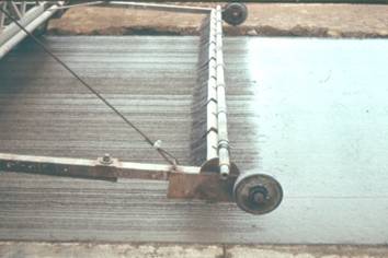
Broom Finish in the Longitudinal
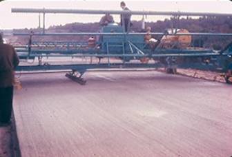
Broom Finish in the Transverse Direction
Concrete base pavement (Item 305) must have a final surface finish that is a uniform, gritty texture as obtained with a broom drag in the longitudinal or transverse direction. No grooves are put in base pavement because it is normally covered with asphalt concrete prior to opening it to traffic.
The broom drag is used in the longitudinal or transverse direction to provide a more skid resistant pavement. The Department has found that new concrete pavement would lose skid resistance after one year of service with merely a light burlap drag prior to tine grooving. Broom dragging roughens the area of concrete between grooves that results in a longer lasting skid resistance.
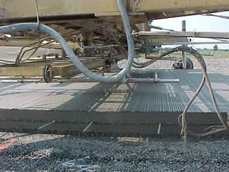
Transverse Grooving by the Cure/Texture Machine (left) and by Hand Methods
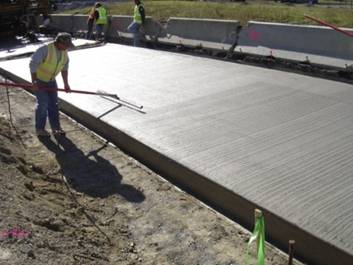
Transverse Grooving by the Cure/Texture Machine (left) and by Hand Methods
The Contractor must put randomly spaced transverse grooves in the plastic concrete immediately after the broom finishing application. The grooves must be spaced in a random pattern at 3/8 to 1¾ inches (10 to 45 mm), with 50 percent of the spacings less than 1 inch (25 mm). All grooves must be in the range of 0.05 inch (1.3 mm) to 0.08 (2.0 mm) deep and 0.10 inch (3 mm) wide. The use of a wire tine rake for the transverse texture grooving can impart the desired groove depth.
Longitudinal tining may be used if approved by the Director. If longitudinal tining is authorized for use, the tine spacing must be placed at a uniform spacing of 3/4 wide with tines 1/8 deep by 1/8 inch wide. Longitudinal tining must be applied using a machine specifically made for this application and must be controlled from a stringline that controls the line and grade of the tining operation.
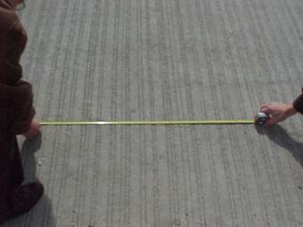
Randomly Spaced Transverse Grooves
Station Numbers
The Contractor is required by specification to stencil complete station numbers into the plastic concrete pavement (Item 451 and 452) each 100 feet (50 meters) before the concrete sets. The dies used to form the station numbers must be 3 to 4 inches (75 to 100 mm) high and 1/4 inch (6 mm) in depth. The numbers are placed parallel to the pavement edge, centered 12 inches (0.30 m) from, and facing the right edge of the pavement. For the purposes of placing station numbers; the right edge is the edge to the right of the normal direction of travel.
The numbers should be impressed into the plastic concrete following the texturing of the surface and before curing is applied. If the impression is made too early, the number will tend to close up and not be as distinct as desired.
For divided highways station numbers must be provided for each pavement direction.
If concrete shoulders are placed with a traveled lane, the station numbers should be placed 12 inches (0.3 m) in from the outside edge of the shoulder and facing the pavement.
Station numbers are not required on concrete base (Item 305).
Concrete Curing
(451.10)
Curing is the treatment or protection provided to concrete during the curing period. Proper curing consists of keeping the concrete moist and warm to insure adequate hydration of the cement. Curing protects concrete from early shrinkage due to changes in temperature and, or loss of moisture before it has developed sufficient strength to resist the resulting tensile stresses.
It is extremely important to provide adequate curing during the first few days, with the first few hours being most important to obtain a strong durable pavement. Strength loss due to lack of moisture during this period is difficult to regain even with subsequent curing.
During windy, hot, dry weather, it is very important that finishing is completed rapidly and the curing be placed before the surface dries out to the extent that plastic shrinkage cracks develop. These cracks can never be sealed, and they are an indication that the surface may have been depleted of the necessary water to properly complete the chemical reaction of cement hydration. Water curing may halt this shrinkage cracking, but the addition of more water will not correct the cracking once it occurs.
In cold weather, the concrete may continue to bleed after finishing. Take care in placing any type of curing under these conditions so that the surface will not be marked.
Prior to the application of any curing material, ensure that it meets the requirements of 705.05, 705.06, or 705.07 Type 2. This also applies to any equipment used in the application.
Liquid Membrane
Curing
For concrete pavement an approved curing membrane must be sprayed on all exposed surfaces using a self-propelled mechanical sprayer with adequate shielding from wind. The curing membrane must be applied at a minimum rate of 1 gallon per 150 square feet as soon as the free water has dissipated from the surface. Approved liquid membrane curing compounds are white in color so that coverage can be readily observed. They are sprayed over the exposed concrete faces while the concrete is still plastic. Hand spraying can be used on pavement with integral curb, for small irregular areas, sections of variable width, and on pavement edges after form removal.
Project inspection should include a daily check of the Contractor’s curing compound application rate to assure that the correct amount of curing membrane was applied to the pavement. To do this check determine the amount of curing compound required for the days placement and compare it to the amount of curing compound actually used by the contractor.
To calculate the amount of curing compound required, the area in square feet (square meters) of pavement that is to be cured must be determined. This area includes the top surface of the pavement plus the area of any pavement edges that are to be cured if the contractor is slip form paving. Once the area has been calculated it is divided by the specified application rate in gallons per square yard (liters per square meter). The formula below is used to calculate the required amount of curing compound in gallons (liters):
Required Gallons = Area (square feet)
Rate (gallons/ square feet)
Required Liters = Area (square meters)
Rate (liters/square meter)
The above equations give the amount of curing compound required in gallons (liters). The amount of gallons (liters) required is compared to the amount that was actually used during the day’s work. The amount of gallons (liters) of curing actually used must be equal to or greater than the required amount of gallons (liters).
If properly applied, these membrane-forming compounds prevent evaporation and the retained water provides excellent curing. Therefore, make sure that the specified rate of application is adhered to and that the curing compound is applied evenly. This ensures that a uniform thickness of membrane coating is obtained. If this is not done, the quality of the concrete pavement will be affected. It should be noted that concrete with a grooved (tined) surface may require more curing compound to obtained complete coverage that a base pavement without tining. The specified application rate is a minimum and the Contractor must use more if the visual coverage is lacking.
White pigmented compound is the only membrane curing compound acceptable on paving projects. This has an advantage over clear type compounds in summer construction in that it provides a coating that reflects heat from the surface. This decreases heat absorption in the pavement and the tendency for transverse cracks to develop during warmer afternoon temperatures. In addition, its white color permits visual inspection for uniform coverage.
The white pigment used in the membrane acts as an abrasive that tends to enlarge the apertures of the spray nozzles and to reduce the efficiency of pumping equipment. Equipment used to apply membrane should be cleaned frequently and checked to see that it is providing a uniform protective covering. Streaks, lines, and dribbles indicate malfunctioning sprayers. The Contractor must correct the equipment to provide uniform, consistent coverage over the entire pavement.
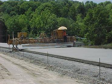
Cure /Texture Machine Applies Curing Compound After Transverse Grooving
Water Curing
A water cure using wet burlap, waterproof paper, or polyethylene sheeting may be used however this type of curing must remain in place for 7 days unless test beams have attained a modulus of rupture of 600 psi. This type of curing should be placed as soon as possible without marring the surface.
The contractor may choose to water cure by placing wet burlap on the exposed surfaces followed by waterproof paper or polyethylene sheeting. Make sure that the pavement is kept wet at all times. This type of curing requires constant checking throughout the curing period. This method is not used very frequently and therefore is not discussed in detail.
Waterproof paper or polyethylene meeting specification requirements (705.05 and 705.06 are placed on the concrete as soon as possible after finishing without marring the surface and are left in place for the full curing period.
The combination of wet burlap and waterproof paper or polyethylene sheeting is less labor intensive than a burlap-only cure because it will keep the concrete wet and does not require regular wetting.
Curing blankets, sheeting, and burlap should be placed to cover the full lane width and lapped at least 12 inches (0.3 m). Edges should be completely covered when forms are removed. This may be done by turning down the edge of the blankets or narrow strips pulled out from under them. These narrow strips are placed on the concrete before main sheets are laid.
Curing materials should never be dragged over fresh concrete and should be placed so as not to mar the surface. One of the principal precautions in this curing method is to make sure edges along forms are sealed so that there is no possibility of air getting under the curing material. This is important because air can circulate over the pavement drying out the surface and resulting in inadequate curing. In addition, heavy winds will get under the blankets and rip them off leaving the pavement without any curing at all.
All physical curing blankets, sheeting, etc, must be free of holes and torn areas and it must be securely anchored against blowing. These types of curing methods must be checked daily.
Removing Forms
(451.11)
The presence of forms during early curing protects the pavement edges against damage and serves as a curing method (for the pavement edges).
During warm weather, the common procedure is to remove the forms approximately 24 hours after the concrete is placed. During cold weather, it may be advisable to leave forms in place for a longer period. In any event, forms should not be removed until the concrete has attained sufficient strength to prevent damage to the concrete surface or breaking of the edges during removal.
The method used to remove the forms should not damage the concrete pavement. In addition, the Contractor should be encouraged to use a method that will not bend or otherwise damage the forms. The method used to move forms away from concrete should ensure that each form section is pulled horizontally away from the edge before it is lifted.
Pin keys should be loosened first, form joint locks unfastened, and nuts removed from the ends of hook bolts (single lane paving). Then, pins should be removed from their sockets using a direct vertical lift without any pressure toward the concrete. The action necessary to exert the vertical lift should be from the forms or the ground outside forms. If any equipment is used to pull pins that may ride on the concrete, make sure that no pressure is on the concrete other than the weight of the equipment.
After pins are removed and other preliminary work finished, light blows with a hammer or careful prying on base flanges may be used to separate forms from concrete. Prying against the concrete edges with bars to break forms loose should never be permitted.
When forms have been removed, edges should be checked immediately and honeycombed areas filled with mortar. Inspect filled areas to make sure the entire areas are tightly packed and struck off flush with surface of the pavement edge.
Curing must be applied to the edges as soon as forms have been removed and edge patching has been completed. This assures satisfactory curing as well as preventing the loss of water necessary for hydration of the cement.
Surface Smoothness
(451.12)
There are two methods that could be used to check the smoothness of a completed concrete pavement. Item 451.12 requires the use of a 10-foot rolling straightedge or Proposal Note (PN) 420 that requires the use of a non-contact profiler to measure smoothness. When PN 420 is required as part of the contract documents, 451.12 does not apply.
When 451.12 apply, the Contractor is required to check the surface smoothness of the completed pavement using a 10-foot rolling straightedge. The rolling straightedge can be a two- or four-wheeled with an indicator wheel in the center that detects high and low areas in the pavement surface. This equipment must alert the operator when encountering any high or low areas of pavement in excess of a preset tolerance. This alert may be by a pointer scale, by audio, or by marking the pavement surface with dye or paint.
Testing is done after the final curing and cleaning of the pavement to detect any surface variations that are in excess of the allowable tolerances. For pavements, the tolerance is 1/8 inch in 10 feet (3 mm in 3.0 m). For ramp pavements and for those pavements that exceed an 8-degree curvature or 6-percent grade, the tolerance is 1/4 inch in 10 feet (6 mm in 3.0 m).
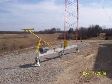
10-foot Rolling Straightedge
The Contractor must tow or walk the equipment over the completed pavement. The Contractor must test two lines, one in each wheel path, in each 12-foot (3.6 meter) lane. The wheel paths are located 3 feet (1 m) measured transversely from the pavement edge on each side.
Proposal Note 420 –
Surface Smoothness Requirement for Pavements
Larger concrete paving contracts (those exceeding 1 mile in centerline length) generally include Proposal Note (PN) 420 Surface Smoothness Requirements for Pavements. When this proposal note is included, the provisions of 451.12 do not apply and the Contractor is required to use the information included in PN 420 to determine surface smoothness. This proposal note requires testing of the surface of completed pavement with a non-contact profiler and software that will produce an International Roughness Index (IRI).
The non-contact profiler must meet the requirements of Supplement 1058. The equipment and operator must be previously approved by the Department. All equipment and operators that are approved are listed on the Department’s web site. The equipment and operator must be checked against the Contractor’s approval letter and against the Department’s web site. The Contractor must demonstrate the use of the equipment prior to its use on the project.
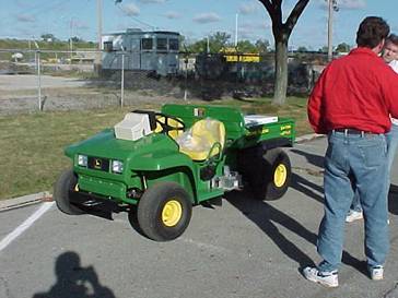
Low Speed Non-Contact Profiler used to Measure Pavement Smoothness

Low Speed Non-Contact Profiler used to Measure Pavement Smoothness
The Contractor is paid a bonus for exceptionally smooth concrete pavement and there are deductions if the pavement is not constructed smooth enough. The pavement must be of a certain level of smoothness to be accepted otherwise, corrective work is required. The IRI is measured for localized roughness for any 25 feet section and for smoothness of any 0.10 mile section. Where there is localized roughness with an IRI greater than 160 inches per mile in 25 feet corrective work is required. For an IRI greater than 95 inches per mile in any 0.10 mile section, corrective work is also required.
Defective work as described under PN 420 includes removal and replacement , or diamond grinding to restore the surface to within the tolerances required.
Profile Grinding
(451.13)
When 451.12 applies and the surface deviations as measured with the 10-foot rolling straightedge must be ground the diamond grinding equipment must conform to Item 257. Bush hammering, carbide tipped grinders, or any method that may damage the bond of the aggregate or shatter the aggregate is not permitted
A 10-foot (3.0 meter) straightedge must be used to check for compliance when corrective work is in progress. The straightedge can also be used to determine the transverse limits of the area to be corrected. Usually variations extend beyond the wheel path and may require diamond grinding and grooving the entire lane width. This determination can only be made by checking with a straightedge.
Low areas should be corrected by grinding on each side until within tolerance. If these areas cannot be corrected by grinding, they must be repaired or replaced to the satisfaction of the Engineer.
Pavement Grooving
(451.14)
It may be necessary to restore transverse grooves in concrete pavement after the concrete has hardened when the finishing operation did not conform to 451.09 and, or when the tining operation did not provide the correct pattern or depth. Grinding to restore trueness leaves a corduroy texture in the longitudinal direction. The randomly spaced transverse grooves must be restored as detailed to the dimensions given in 451.09.
The equipment required for transverse grooving must be self-propelled, power driven machines specifically designed to groove hardened concrete pavement with diamond impregnated blades or diamond impregnated cylinder rings. The blades or cylinder rings must be mounted on an arbor head so that the resulting grooves are randomly spaced. The grooving equipment must have a depth control device that detects variations in the surface and adjusts the cutting head to maintain the proper groove depth.
Note that when pavement is ground to meet the requirements of 451.12 Surface Smoothness or PN 420, the restoration of transverse grooving is not required.
Sealing Expansion
Joints (451.15)
Only expansion joints are required to be sealed. This should be done as soon as possible after saw cutting and before the pavement is open to construction equipment or any other traffic. Proper sealing prevents intrusion of stones and debris into the joint that would keep it from opening and closing as designed with the movement of the pavement.
The Engineer may allow the use of a temporary seal material to allow opening to traffic. This material must be removed prior to the final sealing of the joint.
All joints must be cleaned prior to filling. Cleaning consists of operating a saw blade backward through the saw groove to remove all pebbles, trash, dirt, etc. Any other operation which satisfactorily cleans the groove is permissible. The final step in cleaning consists of blowing out the joint opening using compressed air or by a jet of clean water.
Hot-applied joint sealer (705.04) is required for sealing expansion joints. Since the hot applied sealer requires heating, frequent checks should be made to avoid overheating to a temperature higher than the manufacturer’s recommendation.
Joint walls must be inspected just ahead of filling to make sure that they are dry and thoroughly clean. It is essential that the walls be in this condition if the sealer is to function properly. If the sealer fails to adhere to the concrete, water and foreign material will enter the joint.
Pour liquid sealing compounds in such a manner that complete filling from the bottom of the joint slot to approximately level with the surface of the pavement is assured. With some compounds it may be necessary to fill the joint in several applications. Workers should not allow the sealing compound to spatter or drip onto the adjacent pavement.
The sealing material will run to the low side if the joint is filled too fast. Hot poured compounds may flow out of the joint at the edge of the pavement if some method of plugging the edge is not used.
As air temperature increases, the pavement will expand or lengthen and the joints will close. Conversely, the slabs contract as the temperature falls, causing the joints to open. Joint filling should be such that the surface of the hot-applied sealing material will be approximately level with the pavement surface when the pavement temperature is about 70 °F (21 °C).
Never over-fill a joint to the extent that a bump will be produced at the joint. Such a practice is a waste of material, creates an unsightly condition, and affects the riding quality of the finished pavement. The bumps created by the excessive material will be readily noticeable to the traveling public from a smoothness standpoint, as vehicles pass over each joint.
Prior to final acceptance of the pavement any unsatisfactory joint seal should be removed and replaced. All low spots in sealing compounds must be brought to the desired level, and any high spots should be cut off and the excess material removed.
Opening to Traffic
(451.16)
The completed pavement may be opened to traffic, including construction traffic, after 7 days have elapsed. Or the pavement may be opened to traffic after 5 days provided the modulus of rupture of the test beams is 600 pounds per square inch (4.2 Mpa) or greater.
If it is determined that it will be necessary to open a portion of the pavement in fewer than 5 days, high early strength concrete shall be used, and the pavement may be opened to traffic after 3 days provided the test beams attain a modulus of rupture of 600 pounds per square inch (4.2 Mpa) or greater. In no case should concrete pavement be opened in less than 3 days.
Concrete test beams are required for each 7,500 square yards (6,500 square meters), or fraction thereof, of pavement placed each day. Instruction for making and testing beams are found in Item 499. Beams are tested at the project by the project personnel.
Beams normally are tested at 5 and 7 days. If results are not needed before the end of 7 days, only one beam break is necessary. This break should be made at the age of 7 days.
The maximum capacity of the beam breaker is 1,000 pounds per square inch (6.7 Mpa) and is marked on the beam breaker dial. The capacity must not be exceeded. Beams that do not break when loaded to the capacity of the breaker should be recorded as >1,000 psi (>6.7 Mpa) or whatever the unbroken strength was when the test was stopped, such as 850 psi + (5.9 MPa +) for example.
Slump, air, and yield tests shall be made and recorded each time beams are cast. Concrete for these tests shall be obtained from the same batch of concrete as that was used in casting the beams.
The Contractor is responsible for repairing cracked or deficient pavement at no cost to the Department. These deficiencies include:
· Transverse or diagonally cracked full depth pavement
· Longitudinal cracked full depth pavement
· Spalled pavement surfaces
· Pavement panels which have cement or mud balls
Repair methods are specified in 451.16 and include the following:
1. Transverse or diagonally cracked full depth pavement. Repair with a full depth repair according to Item 255 and applicable standard construction drawings. Repair cracks by replacing the pavement the full width and full depth between longitudinal joints, perpendicular to the centerline and at least 6 feet (1.8 m) longitudinally. Install smooth dowel bars at the interface between the original pavement and the replaced pavement section. Locate and size the repairs to ensure that the repair limits are at least 7 feet (2.1 m) away from any transverse joint. Item 255 and Standard Construction Drawing BP-2.5 applies.
2. Longitudinally cracked full depth pavement. Repair longitudinal cracks within 15 inches (380 mm) of a tied longitudinal joint by routing and sealing the crack according to Item 423. For longitudinal cracks beyond 15 inches (380 mm), repair the same as for transverse or diagonal cracks stated above.
3. Spalled pavement surfaces. Repair spalled pavement with Item 256, Bonded patching of Portland cement concrete pavement.
4. Pavement panels which have cement or mud balls. Repair cement balls or mudballs by coring out the area, full depth with a diamond core bit and replacing the removed concrete with the same concrete as in the pavement. Remove and replace any pavement panel with 5 or more cement balls or mudballs. Locate the limits of the repair along the longitudinal joints and at least 1 foot (0.3 m) past the transverse joints to remove any existing dowel bars. Install smooth dowel bars at the transverse limits of the repairs. Install Type D (Drilled Tied Longitudinal) Joint along the longitudinal limits.
Pavement Thickness (451.17)
The Contractor must cut cores from the completed pavement to check the pavement thickness and to determine a price adjustment if necessary. When the constructed pavement thickness is less than plan by more than 0.2 inches a deduction to the contract bid unit price is made.
One random core must be taken for every (Lot) 2,000 square yards (1,650 square meters) of a pavement unit or a major fraction thereof. Not less than 3 cores will be cut for any pavement unit. For the purpose of coring, the Department will consider the entire pavement area of a specified thickness a unit. The Engineer will determine the locations for the random cores according to Supplement 1064.
Core thickness must be measured by the Engineer in accordance with AASHTO T 148. When a core shows a deficiency in thickness of more than 1/2 inch (13 mm) from the specified thickness the Contractor must take additional cores as directed by the Engineer to determine the limits of the deficiency. Follow the procedures below to determine how and when to cut additional cores:
1. Take a core five (5) feet (1.5 m) longitudinally on both sides of the deficient core. If both cores are less than 1/2 inch (13 mm) deficient in thickness; the zone of deficiency has been determined.
2. If either or both cores are more than 1/2 inch (13 mm) deficient in thickness; cut a core 50 feet (15 m) longitudinally from the deficient core(s). If the 50 foot (15 m) core(s) is more than 1/2 inch (13 mm) deficient, cut additional cores in 100 foot (30 m) longitudinal intervals until a core is less than 1/2 inch (13 mm) deficient in thickness; until the pavement ends; or until overlapping an adjacent pavement Lot’s core in the same lane.
3. If a pavement Lot has cores more than 1/2 inch (13 mm) deficient in thickness and the Lot’s constructed width is greater than 12 feet (3.6 m) obtain cores transverse to the location of the more than 1/2 inch (13 mm) deficient cores. Obtain transverse cores at a location 1/2 the distance from the deficient core to the furthest edge of pavement. Obtain transverse cores for each core more than 1/2 inch (13 mm) deficient in thickness.
4. The Engineer will use the cores that measure less than 1/2 inch (13 mm) deficient in thickness to define the limits of the deficiency. The price adjustment would apply to these limits of deficiency. Note that zone of deficiency is also called zone of deficient thickness.
Price adjustments are based on the pavement average thickness. The pavement is to be constructed such that the thickness is not more than 0.2 inches (5 mm) less than the specified thickness at any location. When this criterion is met the Contractor receives 100% of the contract bid price.
When a core or cores are greater than 1 inch deficient in thickness, the pavement must be removed and replaced. The Zone of Deficiency for the removal is determined as outlined above.
For zones of deficiencies with pavement thickness 1/2 inch to 1 inch deficient the Engineer must calculate the average thickness of concrete pavement to determine price adjustments.
Two averages must be calculated as follows:
1. Calculate a Project Average Thickness (PAT) using all cores from all lots that are ≤ 1/2 inch deficient in thickness.
2. Calculate a Deficient Zone Average (DZA) using all cores with a thickness deficiency of >1 1/2 inch.
Notes: When calculating PAT: Cores > 1/2 inch thicker than the plan thickness are considered to be plan thickness + 1/2 inch for the PAT calculation. For example if plan thickness is 10 inches and the core measured 10.75 inches, use 10 inches + 1/2 = 10.5 inches when calculating the PAT.
The PAT and DZA are used to determine the price adjustment for each section of deficient pavement using the zone of deficiency area previously determined based on the coring operation.
The following table illustrates how the price adjustment is applied:
|
Table 451.17-1 Concrete Pavement Deficiency |
|
|
Deficiency in Thickness as Determined by Cores |
Proportional Part of Contract Price |
|
0.0 to .2 inch (0.0 to 5 mm) |
100 percent |
|
0.3 to 0.5 inch (6 to 13 mm) |
|
|
0.6 to 1.0 inch (15 to 25 mm)* |
|
|
Greater than 1.0 inch (25 mm) |
Remove and replace |
*The District Construction Engineer will determine whether pavement areas from 0.6 inch (15 mm) up to 1 inch (25 mm) deficient in thickness will be allowed to remain in place at the reduced price or must be removed and replaced.
If any deficient core is greater than 1 inch (25 mm) deficient in thickness determine the limits of over 1 inch (25 mm) deficiency by following 451.17, steps 1 thru 4 to determine the limits. Remove and replace those areas greater than 1 inch (25 mm) deficient in thickness.
The Contractor must fill all core holes using the same concrete used in constructing the pavement. When filling the core hole, the surface should be damp and should be painted with a grout consisting of cement and water having the consistency of a thick paint. Stiff concrete should then be rodded into the core hole before the grout dries. The surface should be struck off, and curing membrane applied to provide curing essential for a durable repair.
The pavement areas represented by the PAT of DZA are to be calculated and paid separately.
Deductions are determined and applied to each separately placed width of pavement.
If any pavement area is removed and replaced the replaced pavement must be cored and core values determined are to be included in the average calculations.
Example
A Contractor places 150,000 square yards of 10 inch concrete pavement. The contract price is $38.00 per square yard. If the project average thickness (PAT) is 9.7 inches and the plan specified thickness (PST) is 10 inches, what would the Contractor be paid?
The thickness deficiency is: 10” – 9.7” = 0.3”
From Table 451.17-1 look up the price adjustment for a 0.3” thickness deficiency.
Use that formula to determine the Proportion Part of Contract Price as follows:
Proportion Part of the Contract Price ![]() =
=
![]() =
0.8330
=
0.8330
Then the Contractor’s Payment for 150,000 sq. yd is calculated as follows:
(150,000 sq. yd.) X ($38.00 per sq. yd.) X (0.8330) = $4,748,100
Note that this results in a deduction of $951,900 for this pavement area.
Method of
Measurement (451.18)
Concrete pavement is measured by the number of square yards (square meters) completed and accepted in place. The width of pavement used to calculate the area equals the pavement width shown in the typical sections of the plans. The Engineer will measure the length along the centerline of each roadway or ramp.
Irregular areas of pavement should be field measured and the area calculated in square yards (square meters) for payment.
Any plan changes that involve concrete pavement quantities must be shown fully documented. In addition, any areas found to be deficient in thickness must be documented and the adjustment made in the pay quantity.
Basis of Payment
(451.19)
Payment is made for accepted quantities of pavement by the square yard (square meter) at the contract bid price. If pavement is found to be deficient in thickness, the Department will pay a reduced price according to 451.17.
There is no additional payment for any pavement constructed and found to have an average thickness in excess of the thickness specified.
Documentation Requirements - 451 Reinforced Portland Cement
Concrete Pavement
1. Document subgrade/subbase preparation
2. Document contraction, expansion, and longitudinal joints dowel and tiebar sizes, type; coating; support; placement; spacing
3. Document forms set 100% bearing, correct alignment and grade, rigid, clean and oiled
4. Document length of lap, clearance maintained on steel mesh
5. Document contraction joint spacing; free ends of dowels oiled, dowel assembly tie wires cut; number and size of pins used to hold dowel assembly, alignment of dowels.
6. Document concrete placement including all quality control testing; method of placement, finishing, tining, curing (type and amount), stamping of stationing, weather conditions.
7. Document use of HIPERPAV software, time of sawing, depth and width of sawed joints.
8. Document coring for thickness verification and results.
9. Record results of beam breaks and opening to traffic.
10. Measure length and width for pay.
11. Document on CA-D-3A or CA-D-3B or other approved forms.