632 Traffic Signals and 633 Signal Controllers
Power Service for Traffic Signals (632.24)
Pole and Support Inspection – General
Traffic Signal Supports (632.16)
Method of Measurement for Cable and Wire
Signal Performance Tests and System Checks
Documentation Requirements – 632 Traffic Signal Equipment
Documentation Requirements – 633 Traffic Signal Controllers
632/633 Supplemental Information
General (632.01)
This information is intended to serve as a guide for construction personnel where the Contractor furnishes and installs traffic control devices and appurtenances. However, it may also be useful for maintenance personnel performing the same functions. Inspection procedures for the various type traffic control devices are outlined, mainly in the form of check lists to assist project personnel in performing their duties. This information points out the various important features of each device and references the applicable specification or standard drawing. Illustrations are used for easy recognition of the device or feature being discussed.
Qualified Products List (QPL)
All 632 and 633 devices should be checked against the Qualified Products List before they are incorporated into a project.
Foundations (632.14)
See Item 630 for additional information relative to concerns in the installation of foundations for poles and controller cabinets.
Electrical Appurtenances
General
This section will be used to provide additional information about various electrical appurtenances involved in the traffic signal installations, such as pull boxes, conduit and ground rods.
Pull Boxes
Pull boxes shall be of the specified sizes (see SCD HL-30.11 and the plans), typically 18 inches (460 millimeters) or 24 inches (610 millimeters), and the specified material.
The word on the cover should be “TRAFFIC” when the pull box is part of a traffic signal system unless the plans require the word “ELECTRIC” or other marking. The word shall be formed on the surface or displayed on an attached metal plate in accordance with 725.06, 725.07 or 725.08.
The location of pull boxes shall be as shown on the plans. However, pull boxes in low drainage areas may be adjusted to eliminate drainage problems, or feasible methods of positive drainage may be used in accordance with 603 and details on SCD HL-30.11, with the approval of the Engineer.
Pull boxes located in sidewalks, traffic islands and curbed areas close to the roadway, where wide turning vehicles could drive over them, may be adjusted to eliminate the problem, or a concrete pull box with a heavy duty lid may be used with the approval of the Engineer.
Trench
Trenching shall be in accordance with 625.13 and as shown in TEM Figure 498-7. Any change in dimensions will require approval by the Engineer.
Trenching may be in earth or in paved areas, according to plan details. Trenching and subsequent restoration of surfaces in paved areas shall be in accordance with SCD HL-30.22.
Trenching work in paved areas shall be divided into two pavement depths for payment; less than 6 inches (150 millimeters) and 6 inches (150 millimeters) or greater, as described in 625.20.
The trench in paved areas may be 4 inches (100 millimeters) wide when cut by a Vermeer type trencher. In this case, the trench shall be backfilled with concrete full depth, except that the bottom 4 inches (100 millimeters) above the conduit may be 625.13 tamped backfill.
Conduit
Metal conduit shall comply with 725.04, with sizes according to the plans. It shall be made from domestically produced steel, and the domestic steel content of the conduit shall be certified by the manufacturer or supplier before it is approved for installation.
The routing of loop detector wire in conduit through curb or under shoulder shall be as shown on SCD TC-82.10.
Conduit containing cable and/or wire shall have the terminal at the high end completely sealed in an approved manner, with removable sealing compound or a molded plastic or rubber device compatible with the conduit, cable jacket and wire insulation, according to 625.12.
After placement, a conduit which will not have cable or wire pulled into it during construction shall have a pull wire installed in it, and the terminal at the high end shall be sealed with removable sealing compound, a molded plastic or a rubber device, according to 625.12.
Difficult pulling and possible jacket skinning may occur when an attempt is made to install too many cables or wires within a given conduit. The reason could be design error in new systems or attempts to insert an excess number or size of cable or wire in existing conduit.
Good electrical practice requires that the combined cross section of all cables and wire within a conduit should be less than (or equal to) 40 percent of the conduit inside area:

a1 + a2 + a3 + etc. < 0.40Ci
a = cable or wire across section area, sq. in. (mm²)
Ci = conduit inside area, sq. in. (mm²)
A calculation can be made using the above formula. The cross section area of conduit, cable and wire is shown in TEM Table 497-1.
Ground Rod
A ground rod shall be driven below groundline near the foundation of every strain pole and overhead sign or signal support whether there is power in the vicinity or not, as shown on SCDs TC-21.20, TC-32.10 and TC-32.11.
Ground rods shall comply with 725.16 and be installed in accordance with 625.16. A ground wire of insulated 600-volt No. 4 AWG 7-strand soft drawn copper shall be attached by an exothermic weld. The typical exothermic weld procedure is described in 632.
Insulating varnish shall be applied to the weld and any exposed conductor.
Exothermic Weld
The following procedure is typical and may be used unless the manufacturer’s instructions differ.
1. The end of the ground wire shall be in an un-flattened, unbent, clean and dry condition to assure a good weld.
a. Bent and out-of-round conductor wire will hold the mold open causing weld material leakage. A cable cutter should be used to make un-deformed ends. If a hacksaw is used, the insulation should first be peeled, as the saw tends to coat the cable with plastic material, which must be cleaned off.
b. Corroded cable shall be cleaned. Oily or greasy cable should be cleaned with a solvent that dries rapidly and leaves no residue. Very greasy cable can be “cooked out” by dipping into molten solder.
c. Wet cable can cause the blowing of molten metal out of the mold, and the cable should be dried by a hand torch or a quick drying solvent such as alcohol.
2. Ground rod ends which have been mutilated in driving can hold the mold open and should be cut off. Rod ends shall be clean and dry.
3. The weld mold shall be clean before use. Damp or wet molds can cause porous welds and should be dried by heating.
4. The cable shall be inserted into the side of the mold so the cable is 1/8 inch (3 millimeters) back from the center of the tap hole. The mold shall be placed on the ground rod so the cable sits on top of the rod (see TEM Figure 498-8). A clamp or locking pliers should be used on the rod to keep the mold from sliding down during the welding process, and the conductor should be marked at the mold surface so it can be verified that the conductor has not shifted before the weld is made.
5. The steel disk shall be inserted into the crucible and the cartridge contents poured on top, being careful that the disk is not upset. The cartridge should be tapped when pouring, to make sure the starting powder comes out and spreads evenly over the welding powder. A small amount of starting powder should be placed on the top edge of the mold under the cover opening for easy ignition.
a. The proper cartridge size is marked on the mold tag and is the approximate weight of the powder in grams.
b. If the proper cartridge size is not available, two or more small cartridges or part of a larger cartridge can be used.
6. The mold cover will be closed and the starting powder ignited with a flint gun. If it is necessary to hold down the cover during the flash of igniting powder, a long tool should be used and the hand should be kept away.
Power Service for Traffic Signals (632.24)
General
Power service for traffic signals shall comply with SCD TC-83.10 and the plans. It shall consist of the equipment needed to provide a pole-attached wiring raceway and disconnect switch, for use with separately furnished power cable routed from the service point to the controller cabinet. As shown in TEM Figure 498-9, unless otherwise specified, the equipment includes a weatherhead, a conduit riser with necessary fittings and attachment clamps when required, and a disconnect switch with enclosure (632.24).
A thorough review of the plans should be made to determine that the specific requirements of the maintaining agency for power service have been satisfied.
A ground wire shall be used as shown on SCD TC-83.10, leading to a ground rod installed in accordance with 632.
The LB type fitting under the controller cabinet (SCD TC-83.10) may have to be installed before erecting the pole because of interference with the foundation.
Electric Meter Base
When required, an electric meter base shall be furnished by the applicable utility and installed by the Contractor as part of the power service work.
Conduit Riser and Weatherhead
Power cable is the only type cable or wire permitted through the power service conduit riser.
The conduit riser shall terminate at the meter base, if used; otherwise, termination shall be at the switch enclosure. From there conduit connection to the controller cabinet is as shown on the plans. Conduit connection could be:
1. immediately to the controller cabinet on the same pole;
2. downward by underground conduit and possibly a pull box to a nearby foundation-based controller cabinet;
3. upward by another riser on the pole to span wire and a remote cabinet location.
The conduit riser shall comply with 725.04 and the plans, and the weatherhead shall be threaded aluminum or galvanized ferrous metal (732.16). Risers on painted poles shall be painted to match the poles.
Disconnect Switch
The disconnect switch shall be a UL listed single-throw safety switch or circuit breaker, meeting the voltage and capacity requirements of the specifications. The amperage rating of the fuse or circuit breaker shall be 5 to 10 amperes greater than the peak load rating of the equipment service. The enclosure shall be a UL listed water tight lockable stainless steel NEMA Type 4, supplied with UL listed conduit hubs, and the enclosure shall contain a solid neutral bar normally grounded to the enclosure (732.21).
Pole and Support Inspection - General
See 630 for information about pole and support inspection.
Traffic Signal Supports (632.16)
General
This section will be used to provide additional information about traffic signal supports. Various types of overhead signal supports are also depicted in TEM Table 497-4.
Strain Pole Type Support
Strain poles shall comply with the certified drawings, SCD TC-81.10 and the plans.
They shall be galvanized unless paint is specified in the plans, and the general features should be inspected in accordance with 630.
When strain poles of the embedded type are specified, they shall include an extension for embedment below groundline and a welded-on ground sleeve. The pole extension shall be sufficient to reach within 3 inches (76 millimeters) of the foundation depth as specified in the table in SCD TC-21.20, or the extension may be a minimum of 6 feet (1.8 meters) if a reinforcement cage is provided as also shown on the SCD. The cage shall overlap at least 24 inches (610 millimeters) of the pole extension and reach to within 3 to 4 inches (76 to 102 millimeters) of the foundation’s specified depth. A special foundation design is required when soil with a load bearing capacity of less than 2,000 pounds per square foot (9700 kilograms per square meter) is encountered. Any soil with significant content of clay and/or sand is likely to have a bearing capacity smaller than 2000psi (9700 kg/m2). If any such soil or soil layer is encountered during foundation excavation, arrangements should be made for standard soil bearing capacity tests of the soil at the foundation location. See Section 503, Excavation for Structures, for additional information on bearing capacities of soil materials.
Embedded poles normally do not include a handhole or blind half couplings for internal wiring.
When shown on the certified drawings, and as permitted by 732.11, strain poles may be tapered tubes with a cross section which is circular or a regular polygon of six or more sides, or may be a type consisting of straight sections with a tapered effect accomplished by the use of reducers.
Strain poles used to support traffic signals or signs (SCD TC-17.10) shall be furnished with one or more span wire clamps with shackles for attachment of messenger wire (see SCD TC-84.20).
The messenger wire may be attached by wrapping twice around the pole and securing with a three-bolt clamp, as shown in SCD TC-84.20, when used on round, tapered steel strain poles.
Erection of these poles shall be in accordance with the general procedure given in Section 630, except as noted in this section.
For the initial rake of strain poles of the anchor base type, leveling nuts shall be adjusted to provide a rake of one-eighth to one-half inch per foot (11 to 42 millimeters per meter) of pole in the direction opposite to the contemplated span wires and are to be made snug tight. Further adjustment may be necessary to assure that the strain poles are essentially vertical after the application of span wire load.
For the initial rake of strain poles of the embedded type, poles shall be embedded in concrete to provide a rake of one-eighth to one-half inch per foot (11 to 42 millimeters per meter) of pole in the direction opposite to the contemplated span wire and braced. The age of the concrete before it is considered cured, before the bracing may be removed, and before the permitted application of span wire load, shall be in accordance with 630.
Single Arm Support
Single arm supports shall comply with the certified drawings, SCD TC-81.20 and the plans. General features of the support shall be inspected in accordance with 630, and except as noted in this section, erection of the support shall be in accordance with the general procedure given in 630.
Welds shall be inspected according to 630 and the galvanizing inspected according to 630.
For arms of two telescoping pieces, a 15 inch (380 millimeters) overlap is required. The overlapped arms shall be secured with a stainless or galvanized steel through-bolt with hex head washer and nut(s). Arm caps shall cover at least 50 percent of the end area (732.11).
An arm clamp with clevis shall be furnished at each signal position, as well as a hole with a rubber grommet for the outlet of signal cable.
The installation of small signs and their attachment to the arms should be checked. Any possible interference between swinging signals and signs should also be checked.
Blind half couplings shall be located on the pole of the support for mounting pedestrian signal heads or controller cabinets when required by the plans.
Signal heads shall be installed so that their bottom surface is 16 to 18 feet (4.9 to 5.5 meters) above the roadway. The signals shall be installed at essentially the same elevation. Drop pipes should be used only when necessary to maintain the clearance between 16 to 18 feet (4.9 to 5.5 meters). If the clearance without a drop pipe will be slightly over 18 feet (5.5 meters), it is permissible to omit the drop pipe, with the maintaining agency’s approval.
Initial rake shall be adjusted so that under the load of signals, the pole will assume an essentially vertical position and the arm rise be within the limits specified on SCD TC-81.20, i.e., 3 inches (76 millimeters) minimum and 12 inches (300 millimeters) maximum.
Sag and Vertical Clearance
TEM Figure 498-13 illustrates sag guidelines and vertical clearance standards for traffic signals.
Signal Span Messenger Wire and Appurtenances
General
This section will be used to provide additional information about signal span messenger wire and appurtenances.
Signal Messenger Wire and Cable
Messenger wire and accessories shall comply with SCD TC-84.20 and 732.18. Messenger wire diameter shall be in accordance with the plans.
The height at which the messenger wire is to be attached to the pole will, in some instances, be shown on the plans. In cases where this is not shown, the Contractor is responsible for determining the proper attachment height. This determination shall consider the relative elevation of pavement to pole foundation top, the desired clearance between pavement and the bottom of each signal, i.e., 16 to 18 feet (4.9 to 5.5 meters), the sag in the messenger wire (3 to 5 percent), and the height of each signal.
Alternate methods of attaching messenger wire to strain poles may be used, as follows:
1. Span wire clamp with clevis, anchor shackle and thimbles on the messenger wire,
2. Messenger wire wrapped twice around the strain pole and secured with a three-bolt clamp of the proper size, when used on round, tapered strain poles.
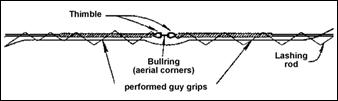
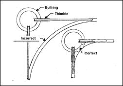
If the messenger wire attachment to strain poles makes use of the alternative with pole clamps and anchor shackles, the wire is to be hooked through the shackle using a thimble and secured with a three-bolt clamp. A preformed guy grip shall not be used for messenger wire attachment at the pole. Guy grips of the proper size may be used at bull rings (aerial corners)
Thimbles with a correct groove size for the messenger wire (or the wire and eye of guy grips) are to be used at anchor shackles and bull rings. When three-bolt clamps are used, the wire tail is to be served as shown in the Section on Messenger Wire. See the Section on Messenger Wire for the installation procedure for preformed guy grips.
Thimbles with a correct groove size for the messenger wire or the preformed guy grip shall be used to connect to anchor-type shackles or to bull rings at span wire aerial corners.
Messenger wire sag shall comply with 632.22 and the Section on Sag and Vertical Clearance.
The signal cable shall be attached to the messenger wire by lengths of preformed lashing rod.
The lashing rod shall be the proper internal diameter to snugly hold the cable, but not cut into its jacket. See the Section on Wire Lashing for further information.
A drip loop shall be formed in the signal cable at each weatherhead, and should extend at least 6 inches (150 millimeters) below the weatherhead (see TEM Figure 498-14).
Cables or groups of cables up to a maximum of four, hanging within pole interiors, shall have their strain relieved by cable support assemblies as described in 632, TEM Figure 498-14 and SCD TC-84.20.
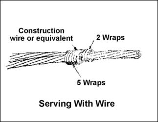
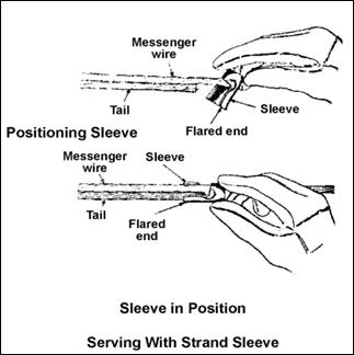
Messenger Wire Served Ends
Messenger wire may be attached to various accessories by looping the wire to make an eye.
The wire end shall be secured by a three-bolt clamp, and the cut wire end or tail shall be “served” with construction wire or clamped with a sleeve device as shown on SCD TC-84.20. The following illustrations show both serving methods for the wire tail:
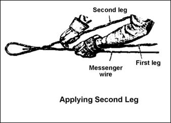
Preformed Guy Grips
Preformed guy grips are made of helically shaped high-strength steel wire. They are available in sizes fitting the outside diameters of messenger wire and form an eye permitting attachment to various accessories.
As shown in SCD TC-84.20, they should be used at bull rings of span wire aerial corners (see the following illustration). Thimbles are used in the eye of grips in accordance with standard details in the SCD.
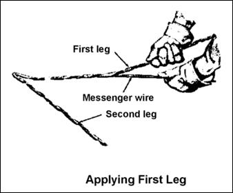
Grips are installed on an end of the messenger wire by wrapping a first leg of the grip to the messenger wire. In most cases, the accessory to which the grip is to be attached must be inserted in the eye of the grip with a thimble before the second leg of the grip is wrapped. The second leg is then applied to the combined first leg and messenger wire. The following illustrations show the wrapping sequence.
Guy grips shall not be used on messenger wire used for span wire sign supports. In this application, wind load on the signs can cause failure of the grips (see SCD TC-17.10). Guy grips shall not be used for attachment to signal strain poles (SCD TC-84.20(5)).
Cable and Wire
In certain instances, the plans will assign a color code usage for each cable, or a typical usage by color code. All connections should be made observing these assignments, and any deviations, if determined necessary, should be recorded. When a color code usage is not provided, good electrical wiring practice would still dictate that color code wiring on the project be consistent.
Typically, white is reserved for the neutral or common leg of a circuit. The following provides additional information about various types of cable and wire contained in Table 732.19-1:
1. Signal cable is used as the electrical connection between signal heads and the controller cabinet at an intersection. The cable may be either IMSA 19-1, which has a jacket of polyvinyl chloride, IMSA 20-1, which has a polyethylene jacket, or IPCEA S-61-402. The number of conductors and wire gage shall be as specified on the plans. Conductors shall be of copper and stranded, and conductor insulation shall be color coded. Splices are not permitted in signal cable (632.23), and the cable should be scanned to be sure that there are none.
a. As temperatures decrease, signal cable gets stiffer and harder, becoming brittle when below freezing. In very cold weather, the cable should be handled with care so as not to damage the jacket or insulation when unreeling, flexing and installing. The method of measurement of signal cable is shown in TEM Figure 498-16.
2. Interconnect cable is used as the connection between intersections for systems of signals (although there is no significant difference between signal and standard interconnect cable).
a. The cable may be either IMSA 19-1, IMSA 20-1 or IPCEA S-61-402 as in signal cable, or twisted pair/shielded interconnect cable conforming to RUS PE-39 may be required by the plans.
b. Twisted pair/shielded cables are less prone to pick up induced current as a result of nearby electrical devices or magnetic fields, and are necessary for certain types of communication systems which may be used to interconnect signals. The number of conductors and wire gage shall be as specified. It should be noted that in the case of twisted pair/shielded cable, the number of conductors is typically referred to as the number of pairs (pair count), i.e., six conductor cable would be referred to as a three-pair cable. Conductors shall be of copper and are usually solid.
3. Interconnect cable of the integral messenger type is aerial self-supporting cable with a "figure 8" cross section. The cable may be either IMSA 19-3, which has a jacket of polyvinyl chloride, or IMSA 20-3, which has a polyethylene jacket. Shielded versions, IMSA 19-4 and IMSA 20-4, may be required by the plans. The number of conductors and wire gage shall be as specified. Conductors shall be of copper and stranded, and conductor insulation shall be color coded.
a. Twisted pair/shielded interconnect cable of the integral messenger type conforming to RUS PE-38 may also be required by the plans.
4. Loop detector wire is laid in turns in saw slots cut into the pavement and routed by the groove to the edge of pavement and to a pull box. The wire is single-conductor No. 14 AWG.
a. The conductor shall be of copper and stranded. Loop detector wire consists of detector wire inserted into a flexible plastic tubing (732.19) meeting specifications IMSA 51-5. The tubing shall encase the wire completely from the splice at the lead-in cable through the entire loop turns and back to the splice.
5. Lead-in cable for detector loops is spliced to loop wire and routed to detector units in the controller cabinet. The cable shall be two-conductor No. 14AWG with jacket of 0.04 inch (1 millimeter) minimum black polyethylene and insulation of polyethylene. Each conductor shall be stranded copper. The conductor pair shall be twisted and shielded.
6. Lead-in cable for magnetometers is spliced to the lead which is a part of magnetometer probes and routed to detector units in the controller cabinet. The cable is four-conductor No. 18 AWG with a jacket of 0.026 inch (0.66 millimeter) minimum high density polyethylene and a low capacitance insulation. Each conductor shall be stranded copper, and insulation shall be color coded. The four conductors shall be twisted.
7. Power cable is used as the connection between the service pole or service drop and the controller cabinet. The cable normally is two-conductor and UL:RHH/RHW/USE type. The wire gage shall be as specified. Conductors shall be color coded, of aluminum and stranded.
a. Stranded copper may be substituted with an AWG one gage higher (wire one size smaller).
b. When specified, power cable may be three conductor. Single conductor cables may be substituted for a two (or three) conductor cable, but color coding should still be provided.
8. Service cable is used to bring power to the vicinity of an isolated intersection. The cable is normally two-conductor (duplex) and XHHW type or cross-linked polyethylene with a 0.045 inch (1.14 millimeter) minimum jacket. The wire gage shall be as specified. The cable is aerial self-supporting with one conductor being an uninsulated ACSR (aluminum conductor, steel reinforced) messenger wire. An insulated conductor of stranded aluminum is twisted around the messenger. Stranded copper with an AWG one gage higher (wire one size smaller) may be substituted for the aluminum conductor. Three-conductor (triplex) may be specified where two insulated conductors are twisted around the messenger wire. The uninsulated messenger serves as the grounded neutral of the power supply.
9. Ground wire is used to connect signal or sign supports to ground rods. The wire shall be single-conductor No. 4 AWG made of seven-strand soft drawn copper with white insulation and rated at 600 volts. The wire is used as part of the 625.16 Ground Rod item.
Lashing of Overhead Cable
A preformed helical lashing rod shall be of the proper internal diameter to tightly secure overhead cable(s) to the messenger wire. A lashing rod should not be loose or so tight as to be impressed deeply or cut into the cable jacket. If either deficiency is observed, the proper internal diameter may be determined by the following formula: C approx. = (0.85) (D+m), where C is the lashing rod internal diameter, D is the cable jacket diameter and m is the messenger wire gage (all dimensions in inches (millimeters)).
For groups of several cables of varying diameter, the internal diameter of the lashing rod may be best determined by a graphic layout to scale.
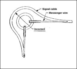
Signal cable routed on messenger wire should neatly pass the bull rings in its path. Also, signal cable routed around an aerial corner formed in the span wire at a bull ring should have a radius in its routing small enough to form a tangency with the bull ring.
Cable Support Assemblies
As shown in TEM Figure 498-14, a cable support assembly makes use of a flexible tubular wire mesh device called a cable grip which has a gentle holding action over its length and which is used to eliminate strain or damage to the jacket of cable(s) hanging in the interior of poles.
The support assembly consists of the grip attached to a single “U” eye support bale and a sling when necessary. The grip may be used on an individual cable or a group of cables up to a maximum of four (see 632.21). The grip shall be the proper size and strength for the cable(s), of stainless steel or tin coated bronze, and may be either a “closed” or “split with rod” type. The split type is used when a cable end is not available. In this application, the grip mesh is not a continuous tubular weave, but is split for wrapping around the cable(s) and is secured by a rod which is inserted through alternate weaves at each side to form a tube.
The support’s bale shall be hung over the pole J-hook if sufficient length is available; otherwise, a sling shall be made of messenger wire, clamps and thimbles. The sling wire is to be passed through the bale eye, adjusted to the proper length and hung on the J-hook.
Pole interiors should be checked by removing pole caps to verify that cable support assemblies are in place, hung on the J-hook and properly adjusted to eliminate cable jacket strain.
Aerial Interconnect Cable
For aerial interconnect cable, the following standards and guidelines apply:
1. Aerial interconnect cable and accessories shall comply with SCD TC-84.20 (illustrated in part in TEM Figure 498-15). Interconnect cable may be supported on separate messenger wire or be the integral messenger self-supporting type with a "figure 8” cross section, if specified on the plans.
2. Metal poles with messenger wire supported interconnect cable are to be furnished with pole clamps. The pole clamp may provide clevis(es) to which the messenger is attached and terminated, or may provide a stud to which a clamp assembly can be bolted.
3. Messenger wire ends are to be looped and secured with three-bolt clamps or a messenger vise, or a preformed guy grip dead end may be used (see 632). If clamps or vises are used, the wire tail shall be served (see 632). Thimbles with a correct groove size for the messenger wire shall be used to connect to the clevis of the pole clamp.
4. When messenger wire is to be grounded to a metal pole, a ground clamp, an insulated ground wire and a bolt tapped into the pole shall be used (also see item 10 in this section).
5. Wood poles with interconnect cable shall be fitted with through-bolts holding a clamp assembly or with a thimble eye-bolt to which the messenger may be attached and terminated.
6. The clamp assembly shall be suitable to the type of cable support, either messenger wire or self-supported cable with "figure 8" cross section. Clamp assemblies for "figure 8" interconnect cable differ slightly from those intended for use with separate messenger, inasmuch as the clamp used with "figure 8" must allow a small gap for the web of the "figure 8" cable which joins the messenger to the cable.
7. When messenger wire or "figure 8" cable is to be grounded on a wood pole, a ground clamp and an insulated ground wire stapled to the pole and covered by a molding shall be used (also see Item 10 in this section). The ground clamp used with "figure 8" cable shall be a type with teeth to penetrate the jacket over the messenger. The ground wire shall be bonded to an existing ground wire or to a ground rod.
8. Standard interconnect cable shall conform to C&MS Table 732.19-1 and have the number of conductors and wire gage specified. There is no difference between standard interconnect cable and signal cable, only in the application. Interconnect cable of the shielded type may be specified in the plans. The interconnect cable should be marked with the correct nomenclature. Solid conductors are not permitted (732.19) unless specified in the plans. Splices may be used on long lengths of interconnect cable (632.23) and shall be accomplished only in weather tight splice enclosures. Splice enclosures may be either aerially located on the messenger wire or be a pole-mounted box type (see SCD TC-84.20). Where the aerial enclosure is clamped to the span, it should be within 2 feet (0.6 meter) of a pole to improve accessibility. No measurement allowance is given for splices.
9. Aerial interconnect cable is to have a sag between three to five percent of pole spans or is to match existing utility lines.
10. Messenger wire supporting interconnect cable, and the integral messenger of self-supporting type cable, is to be grounded in cable runs at the first and last poles and on intermediate poles at intervals not to exceed 1200 feet (366 meters) (also see item 4 of this section for grounding on metal poles, and item 7 for grounding on wood poles).
11. As temperatures decrease, interconnect cable gets stiffer and harder, becoming brittle when below freezing. In very cold weather, the cable should be handled with care so as not to damage the jacket or insulation when unreeling, flexing and installing.
12. Standard interconnect cable may be attached to supporting messenger wire by lengths of preformed lashing rod or by spinning wire. Lashing rods shall be of the proper internal diameter to snugly hold the cable but not cut into its jacket (see 632).
13. Aerial interconnect cable of the integral messenger self-supporting type (with a "figure 8” cross section) shall have its wind stability increased by being twisted or spiraled once every15 feet (4.6 meters) of span. This is done by clamping the tensioned cable to every other pole and then going to intermediate poles and twisting the cable before tightening their attachment clamps.
14. When the interconnect cable is attached to a pole and continues in a relatively straight line past the pole, this is an intermediate support; whereas, if the interconnect cable turns at the pole, it is a corner or turning point. Certain types of clamps may be well suited for intermediate support applications, while other designs are required for corner clamps. The clamps shown on the left side in SCD TC-84.20 are usually not suitable for corner clamps if the change of direction is more than about 10 degrees. See SCD TC-84.21 when the change of direction is more than about 10 degrees.
Method of Measurement for Cable and Wire
TEM Figures 498-16 through 498-20 illustrate the method of measurement for signal cable, interconnect cable, detector lead-in cable, power cable and service cable, respectively. 632.29 also specifies the method of measurement for cable and wire.
Signal Equipment and Wiring
General
This section will be used to provide additional information about other signal equipment and wiring.
Controller Cabinet
While the layout of controller cabinets may vary, the following requirements and guidelines apply:
1. The prewired cabinet should be checked against certified drawings, the wiring diagram for the cabinet and the plans.
2. The cabinet should be fitted with a small door-in-door (police door) unless otherwise specified. The cabinet should be in good condition, revealing no evidence of damage, with its material free of cracks and pinholes. The doors and seals should fit properly. The cabinet exterior should appear as metallic aluminum unless a color is specified. The cabinet interior may be similar to the exterior or may be flat white. The method of cabinet mounting should be as shown on the plans and the cabinet should be securely mounted.
3. Cabinets equipped with solid state controllers shall be provided with a suitable number of sturdy adjustable metal shelves to mount the specified equipment and to provide the required space for designated future equipment (733.03).
4. The equipment shall be arranged for easy withdrawal and replacement, without the necessity of disturbing adjacent equipment. The permanent location of equipment within the cabinet, as well as the shelves themselves, should allow free circulation of air and not restrict air flow from fan ducts or vents. Components on shelves and devices on the door shall be arranged so that a 1 inch (25 millimeter) minimum space separates them when the door is closed. This minimum space shall not be compromised by plugs, wires, controls or similar items. Terminals and panel-mounted devices with exposed contact points located next to shelf mounted equipment shall be provided with spacers, shelf lips or other means to assure that component units cannot be accidentally moved into contact with any exposed electrical terminal points. A minimum 4 inches (100 millimeters) clear area from the bottom of the cabinet should be reserved for the routing of cables. No shelf, component or panel-mounted item shall be located in the bottom 6 inches (150 millimeters) of cabinets, with the exception that terminal blocks only in pedestal or pole mounted cabinets may be installed as close as 4 inches (100 millimeters) to the bottom.
5. Ready accessibility should be provided for items such as load switches, flasher, relays, terminal blocks and fuses which are mounted on or plugged into panels on the cabinet back or sides. Switches, controls and indicator lights should be easily operable and visible without having to move equipment from their positions.
6. Major equipment items should bear a name plate, brand or indelible marking for identification as to type, model, catalog number and manufacturer’s name or trademark.
7. The furnished controller unit should be checked for the correct type, number of phases, and available control functions required by the plans. Controller units should be furnished with all auxiliary equipment necessary to obtain the operation shown in the plans.
8. When specified, other equipment may be a part of the prewired cabinet, such as: a coordinator, an on-street master, interconnection equipment, preemption equipment, time clock or weekly programmer, and special relays.
9. Furnished detector units should be checked to see if the correct quantity is installed, and the proper type used with each loop and each detector phase. When multi-channel detector units are furnished, the plans may require the provision of special cabinet wiring and an adapter harness to allow single channel detector units to be readily substituted.
10. The prewired cabinet should also be checked for the following auxiliary equipment:
a. A forced air ventilating fan automatically controlled by a thermostat shall be furnished.
b. A conflict monitor shall be furnished. When the plans so specify, according to 733.03, an increased capability monitor shall be furnished. The minimum number of monitor channels, related to the number of phases for the intersection, should conform to 733.03.
c. Load switches should be provided in sufficient quantity for the interval sequence shown in the plans. The switches shall be solid state NEMA triple signal type with input indicator lamps. The minimum number of load switch sockets furnished, related to the number of phases for the intersection, shall conform to 733.03.
d. A flasher (or flashers) shall be solid state NEMA type.
e. Relays required for the proper operation of the specified equipment shall be furnished.
f. Lightning protection devices shall be furnished for the protection of solid state controllers. They should be located on the incoming power line and on loop detector leads where these connect to the terminal block. When solid state coordinators are furnished, they should be protected by devices across each conductor and ground on the interconnect cable (see 733.03(A.2.f.)).
g. A convenience outlet and lamp shall be furnished. The outlet should contain at least one standard three-wire plug receptacle of the ground-fault circuit-interrupting type. The lamp should be an incandescent type, located in the upper part of the cabinet, and controlled by a switch.
h. A main power breaker shall be furnished. The fan, convenience outlet and lamp should be wired on a branch of the AC+ power line preceding the main breaker, so that these may be operated independently of the main breaker control. This preceding branch should itself contain an auxiliary breaker rated at 15 amp.
i. A radio interference filter should be installed in the incoming AC+ power line between the main breaker and solid state equipment. If the equipment furnished does not provide signal and flasher circuit switching at the zero voltage point of the power line sinusoid wave form, filters should also be provided for the load switches and flasher.
j. A manual control cord with push button should be furnished only when the plans so require (733.03). The cord should be at least 5 feet (1.5 meters) long.
k. Switches required for the proper operation of specified equipment should be furnished and labeled as to function and setting position. The following switches should be grouped behind the small door-in-door (police door): signal shutdown switch, flash control switch and an automatic/manual transfer switch (when manual control is specified).
l. Terminal blocks should not be obstructed by other equipment. Terminal points should accept spade type wiring terminals except for incoming power terminal points which may be either the type to accept bare wire or spade terminals. Contact between adjacent terminal points may be either by bus bar or by wire jumpers with spade terminals.
11. The incoming power bus should be fed from the line side of the incoming 120 VAC power line after the circuit has passed through the main power breaker. A signal bus relay should control power to the bus supplying power for the signal load switches. The requirement for radio interference filters (733.03) should be adhered to, with the buses supplying load switches and flashers being filtered if load switches do not switch at the zero voltage point of the power line sinusoid wave form. A common terminal bus insulated from the cabinet should be furnished for the connection of the neutral wire of the incoming 120 VAC power line. This common bus should have sufficient terminal points to accommodate all potential cabinet wiring as well as field wiring. A separate common terminal, insulated from the panel, should be used for the interconnect common (if interconnection is a part of the system).
12. The cabinet should include a ground bus bar with an adequate number (at least three) of ground terminal points (733.03). This bus bar should be grounded to the cabinet. The ground bus bar will normally be bonded to the common terminal bus using at least a No. 8 AWG copper wire.
13. Wiring bundles should be neatly arranged and grouped as to voltage and function, and they should be lashed or restrained so that they do not interfere with the access to equipment, including terminal blocks or buses. The harnesses should be of sufficient length and should be easily traced through the cabinet. All conductors should be stranded, with labeled spade type terminals or plug connectors. The wiring should be color coded, with solid white for the AC common, black for the AC line side power (AC+), and solid green or white with green stripes for the safety ground.
14. Incoming cable and wire should be identified by tags or bands (632.05). The size, material and method of tag or band identification should be in accordance with 725.02, except that marking may be by indelible pen on plastic tags instead of embossed letters. The identification on the tags or bands should conform to the wiring diagram for the cabinet and its intersection, with typical abbreviations in accordance with the Table in 632.05 (reproduced in Table 497-2).
15. Two copies of the schematic and wiring diagram for each cabinet and its intersection should be furnished by the Contractor. The diagrams are to be updated to reflect any changes made during construction. The diagrams should be neat and legible, on durable paper, and folded in a moisture-proof envelope fastened to the cabinet interior.
Cable and Wire Identification
As noted in 632.05, cables and wires shall be identified as shown in TEM Table 497-2.
Vehicular Signal Heads and Wiring
Illustrations of the signal head visors, hangers and wiring discussed herein are presented in TEM Figure 498-21.
1. Signal heads shall conform to the plans, 732.01 and SCD TC-85.20. Signal heads shall have the correct number of faces (one-way, two-way, three-way or four-way) and each face shall be made up of the correct number of optical sections (one, three, four or five). Sections shall be of the correct lens size, i.e., 8 or 12 inches (200 or 300 millimeters), color and ball or arrow configuration. Arrow lenses are only to be the 12 inch (300 millimeter) size. It should be noted that arrow lenses are made in Rights, Lefts and Throughs (up). The use of the proper arrow lens should be checked.
2. Lenses shall be aligned properly in their frames so their optical configuration directs most of the light to the forward sector.
3. As noted in TEM Section 420-4.2, signal heads shall have a yellow finish, unless otherwise specified in the plan.
4. Cutaway type visors (732.01) shall be fastened to each optical section, unless open bottom tunnel visors or other types are specified, and the interior finish of the visors shall be flat black.
5. Signals should be clean and the assembly tight. Gaskets should be in good condition and lens door hinges and latches should be in good working order. All openings not used for mounting purposes shall be closed by waterproof caps.
6. Five-section faces, arranged in accordance with SCD TC-85.20 and the plans, are to use galvanized pipe, elbows and tubular hardware, painted to match the signal head.
7. Swinging signals shall be installed in a plumb condition. A balance adjustor should be used only when necessary to achieve plumb (632.06).
8. Swinging signals suspended from a mast arm shall be fitted with a universal hanger permitting swinging in both longitudinal and transverse directions (632.06).
9. When specified by the plans, disconnect hangers shall be used with signal heads.
10. Drop pipes, 1 1/2 inch (38 millimeter) diameter galvanized pipe, are a source of trouble and are aesthetically unattractive; therefore, they are intended to be used only when they are necessary to permit signals to be suspended above the roadway within a clearance of 16 to 18 feet (4.9 to 5.5 meters). Signals supported by span wire, with sag required between 3 and 5 percent (SCD TC-84.20), shall be brought to proper clearance by adjusting the attachment height of the span wire to the poles. Because of the 2 foot (0.6 meter) clearance tolerance, drop pipes should not be necessary in most cases.
11. When the plans so specify, backplates shall be fitted to signal heads.
12. Signal cable shall be routed into the interior of heads through the entrance fitting using a grommet. The cable shall be routed to each face’s terminal block, which is typically in the yellow indication section but may be in the green section. Conductors shall be fitted with spade type terminals and shall be fastened securely to the correct terminal points. Conductors shall be identified according to the wiring diagram. Signal cable shall not be spliced, either between signals or in signal face interiors.
13. External signal cable shall to be fashioned into a drip loop extending at least 6 inches (150 millimeters) below the entrance fitting but shall not chafe on the signal.
14. Lamps may be either incandescent (732.04.B)or light emitting diode (LED) (732.04.C) as specified in the plans Incandescent lamps shall have a clear glass envelope and a rated life of 8000 hours. Lamp sockets shall be rotated so as to position the open portion of each incandescent lamp filament in an upward position. All vehicular signal lamps shall be prequalified in accordance with 732.04(B) & (C).
15. Each face of a signal head shall be oriented to its approach of traffic and its locking device securely tightened. Orientation or aiming of standard signals should be done so that the maximum light intensity from a standard signal is directed slightly below the horizontal center; thus, on a level approach, the face of the signal should be essentially vertical. When an approach to a signal is on a grade, the signal may be tilted slightly to point the signal axis parallel to the grade of the approach. Horizontal aiming should orient the axis of signal display parallel to the centerline of the approach for straight approaches when the signal is over the roadway. When the approach roadway is curved, or when a signal is not over the roadway, the axis should be directed at a point on the approach which is 175 to 625 feet (54 to 191 meters) in advance of the intersection, the distance being dependent on the speed of approaching traffic. For convenience, OMUTCD Table TS-1 has been reproduced in part as TEM Table 497-3.
16. When a vehicular traffic signal head has been erected and faces approaching traffic, it shall either be in operation as a stop-and-go signal or a flasher, or it shall be covered or bagged. This is an OMUTCD requirement (OMUTCD Section 6B-19) and cannot be ignored. Typically, the plans will contain an item for “Covering of Vehicular Signal Heads” which will require the contractor to cover, maintain the covering, and subsequently remove the covering when the signal is ready to commence operation.
17. Normally, the plans will provide the “covering” item for each new signal head, but will not provide them for any existing heads which are to be removed. The intent is that “covering” will be necessary for the new heads until they and their associated controller and wiring have been checked by circuit testing (see 632), while any existing signals at the intersection will continue to control traffic. When the new signals are uncovered and placed in operation, the existing signals can be quickly removed. Specific maintenance of traffic requirements in any plan may require a different means to assure the unused signals are not exposed to traffic.
Optically Programmed Signal Heads
Programmed heads (see TEM Section 420-4.6) shall conform to certified drawings, 732.02 and 732.03, and the plans. They are to have the correct number of optical sections making up each face. Programmed heads have many points of similarity to regular heads. Items 2, 3, 5, 11, 12, 13, 16 and 17 of 632 also apply to these signal heads. For more detailed information, see publications by the manufacturer.
Each optical section shall be fitted with a visor (732.02 and 732.03) and the interior surface of visors shall have a flat black finish.
Programmed heads shall be mounted in a manner permitting little or no motion. If mounted on a mast arm, a rigid adapter shall be used. Heads of more than three vertical sections mounted on a mast arm shall be fitted with pipe backbracing, as shown on SCD TC-85.20. The pipe shall be a minimum of 17 inches (430 millimeters) behind the signal center axis so that adequate clearance is provided for the programming procedure. If heads are supported by span wire, a tether messenger wire shall be attached to a fitting in the bottom of the signal’s lower section.
Customarily the manufacturer’s representative will program the signals, but in accordance with the plans, the contractor is responsible for the correct aiming and masking of the signal so as to be visible to drivers or pedestrians only in the area indicated on the plans.
Signals are pre-tilted to cover most situations. The yellow indication section should be aimed first and the other sections aimed similarly. The housing shall be opened and the lamp collar and diffuser removed. The roadway inverted image should be observed on the surface of the glass with the eye held a distance of 2 feet (0.6 meter) behind. The image observed is where the optics are pointed. The tilt of the integral adapter shall be adjusted so the horizon appears at the lower third of the glass. The adapter screws are then to be tightened. All sections shall be at the same tilt angle.
The signal shall be rotated horizontally so the image on the glass covers the proper roadway lane(s). The bolts of the mounting adapter shall be loosened and the signal rotated around its serrated surface. The movement of traffic should be examined on the glass. When the roadway image appears correct, that is, pointed in the direction where it should be seen, all screws may be tightened. All sections of the signal should now be adjusted and rigid in their mountings, properly aimed and ready for masking.
The yellow indication section of the signal should be masked first since it transmits a brighter image. The other colors can then be masked identically.
Masking requires the use of opaque tape furnished by the manufacturer. The tape shall be applied to the glass, up to the edge, and squeegeed flat to remove air bubbles. The tape initially should be applied horizontally to the glass to cover the image of the sky and that portion of the roadway which is distant. After this is done, tape should be applied to the images on the sides of the lane(s) where the signal is not to be visible. In many cases, signal visibility is desired for a left turn lane only, and visibility to the adjacent through lane should be masked. Excess tape extending beyond the edge of the glass should be trimmed away, taking care not to cut on the surface of the glass.
The reduced area on the glass should be checked to verify that its image is the only area in the roadway which should see the signal. The lamp collar and diffuser may now be replaced and the housing latched.
The boundaries of the area in the roadway where the signal is to be visible should be explored on foot to verify that the head is properly programmed.
Pedestrian Signal Heads
Pedestrian signal heads shall conform to 732.05, certified drawings, the plans and SCD TC-85.10. Signals shall have the correct type of light source and lettering height in accordance with the plans (632.08).
Housings shall have a black finish, unless otherwise specified (732.05). Visors shall be fitted over each message, except one type may have the entire face protected by a flat black sunshade fastened close to the lens. The interior surface of visors shall be flat black finish. Signals should be clean and the assembly tight. Gaskets should be in good condition and lens door hinges and latches in good working order.
Housings shall be positioned with a minimum set back of 2 feet (0.6 meter) from the curb and a height of 8 to 9 feet (2.4 to 2.7 meters) above the sidewalk for adequate clearance. The heads shall be oriented toward their crosswalk and locked securely in position.
Lamps for pedestrian signal heads may be either incandescent (732.04.A) or light emitting diode (LED) (732.04.C) as specified in the plans .
Pedestrian push buttons shall conform to Section 404-2, certified drawings, and 732.06. Push button housings shall have a yellow finish, unless otherwise specified. The push button shall be positioned 3.5 to 4 feet (1.1 to 1.2 meters) above the sidewalk.
Push buttons on metal poles shall be installed over a 3/4 inch (19 millimeters) maximum field drilled hole with edge protected by two coats of zinc-rich paint and a rubber grommet inserted.
The push button housing curved back shall be positioned over the hole, wiring routed through to the electrical mechanism and the housing secured by stainless steel screws. Unused holes in the housing shall be plugged. Push buttons on wooden poles shall have their wiring in conduit connected to a fitting of the signal support.
Signal head supports (conduit and fittings) on wooden poles shall be grounded, using a ground clamp and an insulated ground wire stapled to the pole and covered by a molding.
If specified in the plans, pedestrian signal heads may be covered in accordance with 632.25.
OMUTCD Section 2L-3 addresses standards for the signs used where push buttons are provided to actuate pedestrian signals. The sign legend shall conform to the plans.
Loop Detector Slot and Wire
TEM Figures 498-23 and 498-24 illustrate details related to the following discussion of loop detector slots and wiring.
1. Slots cut into the pavement forming rectangular detection loops shall be in accordance with the plans and SCD TC-82.10.
2. The slots shall be a minimum of 3/8 inch (9.5 millimeters) in width and shall have a minimum depth of 2 inches (50 millimeters) in concrete and 4 inches (100 millimeters) in asphalt concrete. SCD TC-82.10 requires that loop corners be made at a drilled or bored hole, about 1 1/4 inches (32 millimeters) in diameter, and with the same depth as the saw slot. Any sharp edges at the saw slots and the holes shall be chiseled out.
3. The slot depth shall accommodate the specified number of turns of wire laid so that the uppermost wire has a covering of at least 3/4 inch (19 millimeters). The number of wire turns shall comply with the plans and the table in SCD TC-82.10 (also shown in Figure 498-23). A separate slot leading from the loop to the pavement edge is typically cut for each loop.
4. When permitted by the Engineer, loops installed in new asphalt concrete may be sawed and the loop wire(s) embedded with sealant in a subsurface course with subsequent covering by the surface course.
5. Some plans may specify the use of preformed loops placed on the pavement for covering by a surface course of asphalt concrete.
6. If the problem of loop installations in brick streets is encountered, the Engineer should consult with the local traffic engineer for recommendations.
7. Loop locations may be adjusted to avoid manholes. Loops should not be placed across pavement joints. Instead, lateral and longitudinal adjustments should be considered, with the approval of the project engineer. If joint crossing is unavoidable or major pavement cracks are encountered, the following techniques may be used (see Figure 498-24).
a. In Technique A, the loop wires are laid over the joint or crack within a 3 inch (75 millimeter) square or circular hole cut to slot depth. The wires are laid in an “S” shape and the hole filled with elastic joint material or asphalt concrete.
b. In Technique B, the slot at the joint or crack is saw cut to twice-normal width and depth. The wires are laid so as to conform to the deepened slot which is injected with soft setting butyl rubber up to the depth of the original slot. The original slot depth and the remaining perimeter of the slots are embedded with standard sealant cured to a flexible state.
c. In Technique C, the slot at the joint or crack is enlarged. The wires are encased in a length of plastic tubing which should be large enough to loosely hold all wires and may be slit lengthwise to facilitate construction. Before placing it in the slot, the ends and the longitudinal slit are to be taped shut to prevent the entry of loop sealant. The enlarged slot is then filled with loop sealant.
8. Before loop wire is placed, all slots shall be brushed, blown clean of loose material and completely dry.
9. Loop detector wire shall be single-conductor No. 14 AWG insulated wire, type IMSA 51-5 with stranded copper conductors, unless otherwise specified. The wire should be marked at intervals with the wire gage, UL label and type. The detector wire is contained inside a flexible plastic tube, as required by IMSA 51-5.
10. The correct turns of loop wire (TEM Figure 498-23), up to a maximum of four, shall be placed in the slots, to comply with 632.23 and the plans. The wire shall be pushed to the bottom of the slots with a blunt wooden tool (or equivalent) to avoid damaging the insulation.
11. The wires with tubing at the pavement edge or curb shall be led into a conduit of the size shown in SCD TC 82.10. Care should be taken to prevent excessive slack at the point where the wires enter the conduit. The high end of the conduit shall be sealed in accordance with SCD TC 82.10.
12. The detector wire shall be twisted in the conduit leading from the pavement edge to the pull box. The flexible plastic tubing shall cover the wire completely from the splice at the lead-in cable, through the entire loop turns and back to the splice. The tubing provides extra protection from abrasion and allows the wire to slide inside the tubing in case of pavement shift or cracks, thus minimizing the possibility of breakage. Since wire/tubing includes an air pocket, it will tend to float to the surface when sealant is applied to the slot. For this reason it is usually necessary to wedge short lengths of the tubing, or similar devices, into the slot to wedge down the tubing/wire. These are usually needed at 1 to 2 foot (0.3 to 0.6 meter) intervals.
13. The slots shall be completely filled with approved sealant and left undisturbed until cured to a flexible state. Sealants on the ODOT prequalified list shall be used, in accordance with the manufacturer’s recommendations. Materials which set up to a hard or brittle state are not acceptable.
14. Detector loops are measured as “each” loop installed and the item includes wire, pavement cutting and sealant.
Loop Detector Lead-In Cable
Unless otherwise specified, loop detector lead-in cable (Table 732.19-1) shall be two conductor No. 14 AWG twisted pair shielded, with a jacket of black polyethylene 0.04 inch (1 millimeters) thick minimum, and polyethylene insulation with conductors of stranded copper.
Within the pull box, loop wire ends shall be joined to the conductors of the lead-in cable by soldering and covered with insulating material (see TEM Figure 498-25). An approved, poured epoxy waterproof splice kit shall be used. It is understood that epoxy splice kits are easily damaged by freezing temperatures encountered prior to mixing. Damaged epoxy components may sometimes be recognized if either of the components has turned or is streaked milky white.
Lead-in cable shall be routed to the controller cabinet, fitted with soldered spade type terminals and fastened to the correct points of the terminal block. The lead-in cable’s shielding shall be grounded to the ground bus within the cabinet.
If a pull box is not specified on the plans, the splice between the loop wire and lead-in cable shall be made in the first entered pole or pedestal, except where the controller cabinet is mounted on the pole or pedestal. If the controller cabinet is mounted on the pole or pedestal, the loop wires may be routed directly into the cabinet and no lead-in cable is necessary.
Loop detector lead-in cable is measured in accordance with Section 632-9 and TEM Figure 498-18.
The poured epoxy splice in the pull box is included.
Magnetometer Probes and Lead-In
Magnetometer sensor probes (TEM Figure 498-26) may be set in the pavement, or under and in bridge decks in accordance with SCD TC-82.10 at the locations shown on the plans.
Although core drilling may be performed after concrete placement, it is preferred that probe holes in new concrete be formed by pouring concrete around a vertical piece of capped vinyl-chloride or other non-metallic tubing. Probe holes in existing concrete must be core drilled. Probe installations under bridge decks may be as shown in Figure 498-26. The lead from probes should be in non-metallic conduit. Probes in bridge slabs should be centered in the reinforcing steel grid square which is nearest to the probe’s plan location. The center of a grid square may be located by the use of a Pachometer metal locator. The procedure for use of such an instrument is given in Section 632-10.10.
Probe holes in pavement and bridge decks shall be approximately 3/4 inch (19 millimeters) greater than the probe diameter. The probe shall be set so as to have a covering of at least 1 ½ inches (38 millimeters). However, deeper placement may be used if recommended in the manufacturer’s instructions.
The probe lead, which is a part of the probe(s), is to be led from the probe(s) to the edge of pavement, to the bridge parapet wall or under the bridge deck, depending on the design used.
When in pavement and bridge decks, the slot for the lead shall be a minimum of 3/8 inch (9.5 millimeters) in width and have a depth of 2 inches (50 millimeters) in concrete and 4 inches (100 millimeters) in asphalt concrete.
Probe holes and slots are to be brushed, blown clean of loose material and completely dry. The probes are to be set and leads pushed to the bottom of slots with a blunt wooden tool (or equivalent) to avoid damaging the insulation. Probe holes and slots are to be completely filled with approved sealant and left undisturbed until cured to a flexible state. The sealant should be the same as for loop detector slots, as given in 632.
Probe leads in slots at the pavement edge or curb shall be led into a 3/4 inch (19 millimeters) conduit connecting to a roadside pull box. Care should be taken to prevent excessive slack at the point where the lead enters the conduit. The high end of the conduit is to be sealed in accordance with SCD TC-82.10.
Unless otherwise specified, lead-in cable (Table 732.19-1) shall be four-conductor No. 18 AWG color coded, twisted, with a jacket of 0.026 inch (0.66 millimeters) minimum high density polyethylene and a low capacitance insulation with conductors of stranded copper.
Within the pull box, the probe lead ends shall be joined to the conductors of the lead-in cable by soldering and covered with insulating material. An approved poured epoxy waterproof splice kit shall be used. The kit should be the same as for loop detector lead-in cable as given in 632.
Lead-in cable shall be routed to the controller cabinet and fitted with soldered spade type terminals and fastened to the correct points of the terminal block. The shielding of lead-in cable shall be grounded to the ground bus within the cabinet.
The installation of magnetometer probes includes: the probe(s) and lead, the provision of probe holes and pavement slots when used, sealant for the probe holes and slots, and plastic conduit where required. Probes are measured as individual units with the attached lead. Several probes may be on a single lead.
Magnetometer lead-in cable is measured in accordance with 632 and TEM Figure 498-19. The poured epoxy splice in the pull box is included.
Use of Pachometer Instrument
A Pachometer is an instrument used to detect the location of metal such as reinforcement bars under a concrete cover. The instrument is a magnetic detector which operates on the principle of the change in magnetic flux due to the presence of ferrous metal.
A probe is connected to the instrument and is passed over the concrete surface being examined. The instrument will indicate when the pole of the probe is parallel to and directly over the axis of a reinforcing bar. Use of the instrument will, therefore, outline the sides of a grid square for accurate magnetometer probe location in the center.
Signal Performance Tests and System Checks
General
Traffic control signal components and the entire system shall be tested as required by various specifications to assure proper operation before acceptance. Ground rods shall be tested for satisfactory low resistance to ground. A circuit test should be performed on all conductors to make sure there are no shorts, crosses and high resistance or other improper connections. A cable insulation or Megger test shall be performed on all conductors to verify the integrity of the insulation covering. All traffic control equipment in the controller cabinet should be checked for correct settings and all controls manipulated for assurance of an operable system.
Finally, the traffic control system shall successfully pass a ten-day performance test, which will give an opportunity for any hidden flaws to reveal their presence. As a final “housekeeping” check, equipment should be observed for any evidence of unattached ground wire, unlatched or unbolted doors, etc.
The results of the various tests are to be entered by the contractor on test report forms (TEM Form 496-6) as required by 632.28.
Ground Rod Test
All ground rods shall be tested by the Contractor for earth resistance to ground, as required by 632.28(B).
Short-Circuit Test
Before the performance of any cable insulation (Megger) test or the ten-day performance test, a short-circuit test shall be performed by the Contractor using a volt-ohmmeter or other approved instrument (TEM Form 496-6 and 632.28(C)). Short-circuit tests shall be conducted with all electrical loads, power sources, equipment grounds, and earth grounds disconnected (see TEM Figure 498–28).
Signal cable routed to signal heads may be tested with connection made to the lamp sockets, but without the lamps being installed.
Each conductor shall be measured against every other conductor and ground to assure that no short-circuits, cross-circuits, or other improper connections exist. Continuity should not exist between any conductor and any other conductor including ground.
Circuit Continuity Test
Each circuit branch shall be disconnected and tested by the Contractor for continuity by temporarily jumpering each branch at its termination and measuring the temporarily looped circuit for assurance that no open circuits exist (TEM Form 496-6 and C&MS 632.28(D)). This testing is illustrated in TEM Figures 498-29 through 498-32. Each circuit branch should be according to plan, with no high resistance connections and with the proper identification.
Lead-in cable for loop detector wire shall be tested before and after the cable is spliced to the loop wire.
Circuit continuity of signal cable may be done by applying 120 volts to each outgoing circuit and observing that only the specific lamps are lighted.
Cable Insulation Test (Megger Test)
This testing is illustrated in TEM Figures 498-33 and 498-34.
1. Each conductor of cable or wire terminating at the controller cabinet shall be tested by the Contractor for insulation resistance measured to ground (TEM Form 496-6 and C&MS 632.28(E)). A listing of the resistance reading for each conductor is to be included in the test results furnished to the Engineer.
2. Cable and wire insulation can be faulty but the imperfections can be easily overlooked, leading to eventual electrical failure of the wiring. Weakening of insulation properties may be caused by poor storage conditions and stress due to rough handling during installation. Dirt is especially troublesome, since it is an electricity conductor and can penetrate small cracks in the insulation.
3. Insulation testing shall be performed with all conductors disconnected from their points on the terminal block in the cabinet so there is no chance of any voltage being present, and to prevent damage to any connected equipment. One Megger instrument terminal shall be attached to a termination of jumpered together ends of conductors or to the end of a single conductor cable or wire undergoing testing. The other Megger instrument terminal shall be attached to the cabinet ground bus bar.
4. Insulation resistance shall be measured for the wire of roadway loops after the embedding of the wire with sealant in slots.
5. The meter pointer of the Megger instrument (or equivalent indication) should be adjusted to zero and the test switch activated. Test duration should be as recommended by the instrument manufacturer.
6. The insulation resistance measured to ground for each conductor shall not to be less than 10 megohms. Cable or wire not meeting this reading shall be replaced.
7. After completion of the cable insulation test, all cabinet wiring shall be connected in accordance with the wiring diagram. The Contractor shall demonstrate to the satisfaction of the Engineer that all circuits are continuous and operating correctly, free from shorts, crosses and unintentional grounds.
Functional Test
Before energizing the traffic signals the following functional checks should be made:
1. The incoming AC voltage should be checked.
2. Operation of the following equipment should be checked: cabinet ventilating fan, fan thermostat, and convenience outlet with lamp (when furnished). The filter(s) used with the fan should be unobstructed.
3. Timing settings on solid state controllers should be varied over their ranges and all functions activated to verify that the controls are operable without fault.
4. Timing settings in accordance with the plans should now be entered on the controller, time clock, etc. and checked for corrections. On some projects, timing settings will be provided by the maintaining agency and are not listed in the plans.
5. An agreement should be reached with the contractor and the maintaining agency on the procedure to be followed in the event of a signal failure prior to acceptance.
6. Before signals are energized to control traffic, the maintaining agency should be notified and given an opportunity to check the installation and timing settings.
After energizing the traffic signals the following functional checks should be made. In the event the signals are controlling traffic at the time, these checks should be made with caution to protect the safety of workers, pedestrians and drivers.
1. The function of all cabinet switches should be checked, including the power on/off switch and manual control (when furnished).
2. The traffic signals (and controller indicator lights) should be observed to verify that the controller is timing consistently the intervals and phases set into the controls. A stopwatch is suggested, especially to check critical short intervals. All controllers functions should be activated to verify that operation is proper.
3. The detector units should be investigated to determine which pavement loop(s) or other type sensor is associated with which unit. The visual indication of units (light, meter, etc.) should be observed to determine that each vehicle (truck, car, motorcycle, etc.) entering sensor areas is properly detected on the associated unit and that no extraneous calls occur when the sensor area is vacant. When a detector unit is set for "presence," a detection call should continue as long as a vehicle is positioned over the associated sensor. Concurrent with detection, the appropriate controller indicator light should also exhibit the detection.
4. The flasher switch should be activated to cause the signal heads to flash. Their indications should be checked to verify if they are correct. The flasher switch is then to be returned to the normal or signal mode and a check made of the resumption of normal stop-and-go operation.
5. The conflict monitor should not be activated by normal signal operation or by the manipulation of cabinet switches. If at any time the monitor is activated, the contractor is required to determine the cause of the problem and make appropriate changes and adjustments before beginning the ten-day performance test. The Contractor should test the conflict monitor by artificially causing a number of different conflicting indications and checking that at each test the monitor causes the signals to begin flashing and places the controller in a "stop timing" mode. Artificial conflict may be caused by touching a jumper wire between two load switch outputs that would signal a traffic conflict. Other methods of artificially caused conflicts may be used at the discretion of the contractor.
6. Signals which are interconnected should be observed to determine if offset relationships are maintained in accordance with settings during all periods of the day.
7. When preemption equipment is furnished as part of the cabinet installation, the proper functioning of the equipment should be checked. The equipment should be activated and observations made to determine if the required sequence of intervals and phases is called for in a correct and safe manner.
8. On projects having equipment furnished for future use only, the equipment should be checked to verify that it is properly installed and operable in a correct manner.
Some signal control equipment, such as time clocks (or switches) and weekly programmers, are intended to vary the timing patterns at different periods of the day or days of the week. To determine if these required changes are occurring at the proper times, it is necessary that observations be made to check the operation at transition times over a period of several days.
The change in timing shall not be extremely drawn out or abrupt. The accuracy of time clocks and weekly programmers should be checked. Programmed changes should occur within five minutes of scheduled times for clocks of the electromechanical type and within one minute for clocks of the solid state type. No significant cumulative clock error should be noted during the ten-day performance test.
After successful completion of the ten-day performance test, and after a partial or final acceptance of a project, the Contractor is to turn over to the Engineer all manuals, diagrams, instructions, guarantees and related material, as required by 632.05. It is recommended that the Engineer list this material in the project diary as a permanent record of the transfer. The Engineer should transfer the material to the maintaining agency. For ODOT-maintained signals the material should be given to the District Roadway Services Manager.
After a traffic control system project has been accepted by ODOT, the Engineer should immediately notify the maintaining agency that as of a certain exact time and date, the agency is responsible for the operation and maintenance of the system.
Ten-Day Performance Test
Before acceptance of the traffic control system, the Contractor shall furnish all personnel and equipment required to successfully operate the system continuously for ten consecutive days without major malfunction or failure (632.28(G)).
At least seven days prior to the beginning of the performance test, the Contractor shall notify the Engineer of the starting date. The Engineer will notify the maintaining agency (632.28(G)).
The Contractor shall arrange with the utility supplying the power for purchase of the energy required to conduct the test. All costs of personnel, equipment, electrical energy and incidentals required to perform the test are to have been included in the contract unit prices for the respective items tested.
Minor failures such as lamps, a single detector or an individual signal head, etc. shall be immediately replaced or repaired and will not cause restart of the test.
A major malfunction or failure, such as a master or local controller, interconnect equipment, etc. will cause termination of the test, and after replacement or repair of the malfunctioning or failed equipment, the beginning of a new ten-day test.
Items which have been repaired or which are replacements are to be monitored by the Contractor for a period of ten days to provide assurance of their reliability.
The complete test results are to be furnished to the Engineer on test reporting forms in accordance with 625.19. The Contractor is to record in the test results the beginning and end of the test, and the method and date of the correction of each fault.
The Engineer should record the following events in the project diary: the date of the beginning of the ten-day performance test, a day-by-day record of faults as they occur during the test, and the date of the successful completion of the performance test.
Final Signal Installation Check
After all wiring is completed and all testing completed and accepted, a final inspection of the traffic control system should be performed to assure a neat and workmanlike appearance.
1. All spare conductors should be connected to the ground bus bar in the controller cabinet.
2. All ground wires should be properly connected.
3. The spade type ends of conductors should be sound. After all testing is completed, they should be reinstalled on their correct points of terminal blocks and tightened.
4. A visual check should be made for any signs of arcing, melted insulation, etc.
5. All debris from wiring work or packaging materials should be cleaned from the bottom of cabinets.
6. Cabinet vents should be checked to assure that they are unobstructed and all filters should be clean and in place.
7. Duct sealing material shall be used to seal the conduit entering the cabinet from the base.
8. All doors on the optical sections of vehicular and pedestrian signal heads shall be closed and latched.
9. No wires or cable should be visible under the base plates of poles and pedestals.
10. The handhole covers on poles and end-frames shall be securely fastened.
11. Pedestals with transformer type bases shall have the access door securely fastened.
12. The covers on pull boxes shall be securely bolted.
Documentation Requirements - 632 Traffic Signal Equipment
1. Review certified drawings prior to work commencement
a. Document depth and width of cut for detector loop wire in pavement
i. Cuts blown clean
ii. What kind of material used to fill cuts after loop placement
b. Foundations
i. Excavate as per 503.04
ii. Perform concrete work as per 511
iii. No load applied for 14 days, 7 days with beam break of 650 pounds or more
c. Document each type of equipment installed as per certified drawings provided by supplier and as per individual specifications included in 632.
2. Test as per 632.28
3. Measure and pay per 632.29 and 632.30
Documentation Requirements - 633 Traffic Signal Controllers
1. Review certified drawings prior to starting work
a. All electrical parts of sufficient capacity and marked per 633.03
b. Diagrams and manuals furnished to engineer before installation. Documents modified upon completion of work
i. Controllers tested and pre-qualified as per 633.06
ii. Individual items provided and documented as per items 633.07 thru 633.17
iii. Test in accordance with Item 632.28
iv. Measure and pay as per 633.18 and 633.19
v. Record Serial numbers for all LED signal lamps installed in the project
632/633 Supplemental Information
Please refer to the Traffic Engineering Manual (TEM) for a complete list of forms, supplementary information, and updates. The following figures are examples of typical installations, and forms.
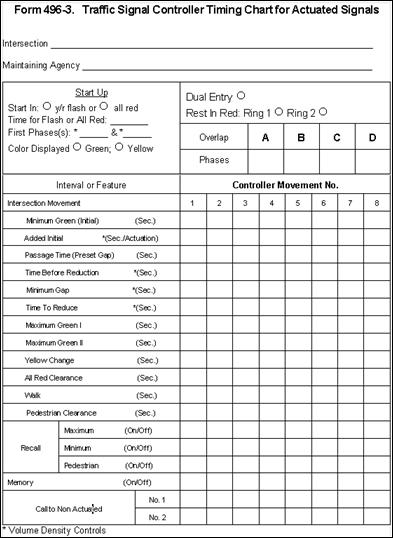
Form 496-3 Traffic Signal Timing Chart
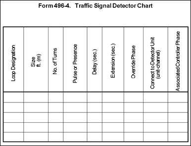
Form 496-4 Traffic Signal Detector Chart
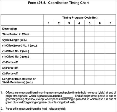
Form 496-5 Coordination Time Chart

Form 496-6 Report of Electrical Tests
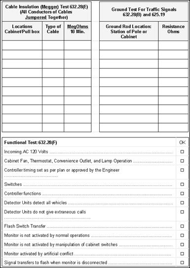
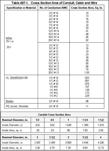

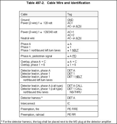
Figure 498-6. Concrete Pull Box
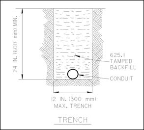
Figure 498-7. Trench Details
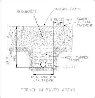
Figure 498-7. Trench Details
Figure 498-7. Trench Details
Figure 498-8. Exothermic Weld
Figure 498-9. Power Service

Figure 498-10. Strain Pole Supports
Figure 498-11. Strain Pole Attachment Details
Figure 498-12. Single Arm Support
Figure 498-13. Sag and Vertical Clearance Diagram
Figure 498-14. Cable Support Assembly
Figure 498-15. Aerial Interconnect Cable
Figure 498-16. Method of Measurement for Signal Cable
Figure 498-17. Method of Measurement for Interconnect Cable
Figure 498-18. Method of Measurement for Detector Lead-In Cable
Figure 498-19. Method of Measurement for Power Cable
Figure 498-20. Method of Measurement for Service Cable
Figure 498-21. Vehicular Signal Heads
Visors for Signal Heads
Hangers for Signal Heads
Figure 498-21. Vehicular Signal Heads
Wiring a Signal Head
Figure 498-22. Pedestrian Signal Heads
Figure 498-23. Loop Detector Placement and Installation
|
Loop Perimeter feet (meters) |
Number of Turns |
|
|
40 |
(less than 12) |
4 |
|
40-160 |
(12 to 49) |
3 |
|
over 160 |
(over 49) |
2 |
Loop Construction
Figure 498-24. Loop Detector Slots and Wiring
Figure 498-24. Loop Detector Slots and Wiring
Figure 498-25. Loop Detector Wiring
Figure 498-26. Magnetometer Probes and Lead-In
Figure 498-27. Ground Rod Testing
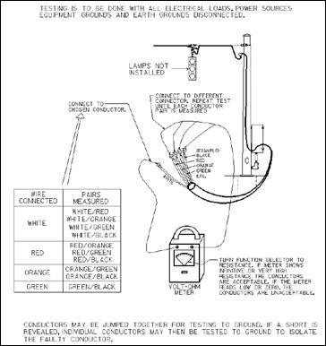
Figure 498-28. Short-Circuit Test
Figure 498-29. Circuit Continuity Test of Loop Wire
(Before Splice to Lead-In Cable)
Figure 498-30. Circuit Continuity Test of Loop Wire and Lead-In Cable
Figure 498-31. Circuit Continuity Test of Signal Cable
Disconnected from Heads or Other Cables Such as Interconnect and Loop or
Magnetometer Lead-In
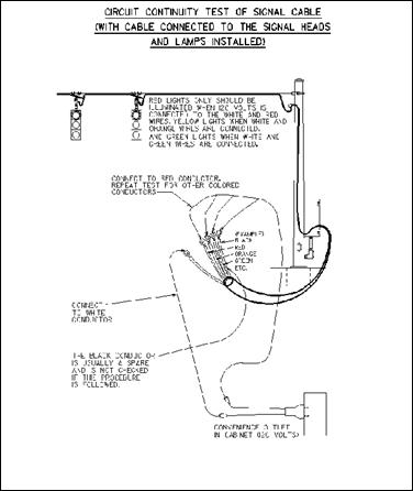
Figure 498-32. Circuit Continuity Test of Signal Cable With Cable Connected to the Signal Heads and Lamps Installed
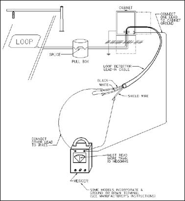
Figure 498-33. Cable Insulation Test (Loop Detector
Wire)
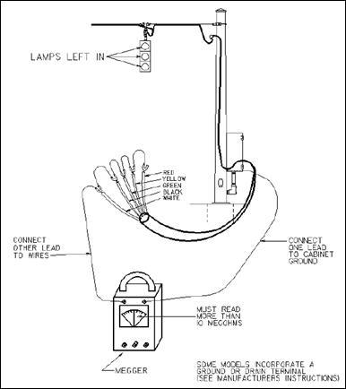
Figure 498-34. Cable Insulation Test (Signal Cable)

Figure 498-35. SCD TC-81.20 Signal Support Design Chart
Figure 498-36. Plan Details for Strain Poles
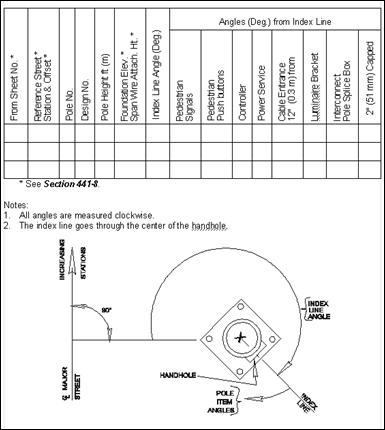
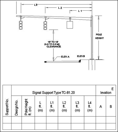
Figure 498-37. Plan Details for Signal Supports - Arm Lengths
(table is continued in Figure 498-38)
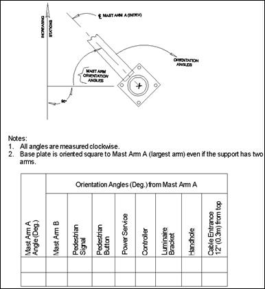
Figure 498-38. Plan Details for Signal Supports - Mast Arm Orientation
(table continued from Figure 498-37)