SS-840 Mechanically Stabilized Earth (MSE) Walls
MSE Wall Construction Do’s and Don’ts
Out of Tolerances Conditions and Possible Causes Criteria
Documentation Requirements – 840 MSE Walls
Introduction
MSE Walls have been constructed in the State of Ohio for over 20 years. In previous years, there were special provisions in the contract that detailed the construction and design requirements. In the old special provisions each wall supplier had a unique special provision. The new supplemental specification (SS-840) combines all of the special provisions into one document.
SS-840 is being updated frequently. Check the plans and addenda to see which version is included in the contract. If a more recent version is available, consider adopting the new version by a change order. There may be a cost or savings involved with adopting the new version, depending on what has changed.
Below is a detail of a typical MSE Wall application. This is an elevation view of a MSE Wall and bridge.
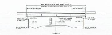
Figure 840.01.A MSE Wall Elevation View
For the same bridge a plan view is shown below.
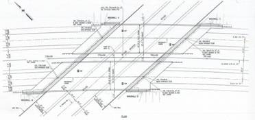
Figure 840.01.B Plan View of the MSE Wall and Bridge
MSE wall specifications are different than the normal construction specifications. There are both design and construction criteria in the specifications. The plans will detail a three line diagram of the MSE wall structure. The internal details and the construction shop drawings are submitted later after the sale of the project.
This detail shows the reinforcing mesh in general form and the undercut.
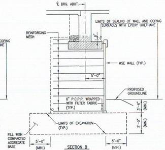
Figure 840.01.C Typical Plan Cross Section of a MSE Wall
In the detail below the Designer has laid out the select granular backfill and 203 embankment.
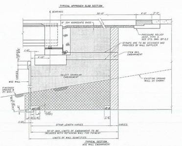
Figure 840.01.D Layout of the Select Granular Backfill and 203 Embankment
There are applications where the designer may choose to place a wall on both sides of an embankment as detailed below.
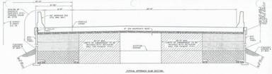
Figure 840.01.E MSE Walls on Both Sides
Specification Changes
Some of the major changes are detailed below:
1. The separate special provisions for individual wall manufactures were converted into one supplemental specification.
2. More construction details were added to control the work in the field better.
3. Step by step construction process is detailed.
a. Foundation compaction improved.
b. Undercut and drainage details were added.
c. Leveling pad width increase to 24 inches.
d. Horizontal and vertical alignment and joint spacing details were added. The flashlight test was added.
e. Fabric gluing method is detailed.
f. Step ups overhangs were addressed.
g. Granular backfill placement and compaction requirements were modified.
h. Reinforcing steel connections details were added.
i. Pile sleeve backfill material changed from bentonite-cement slurry to sand.
4. The design requirements were expanded upon.
5. Added the requirement for the Office of Structural Engineering to review the shop drawing.
General Information
The following figure details the general configuration of the MSE Wall system.
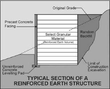
Figure 840.01.F Typical Section of an MSE Wall Structure
Terms
The following are standard terms that will be used throughout this text.
Coping - The coping is used to tie in the top of the wall panels and to provide a pleasing finish to the wall top. It is cast in place.
Filter Fabric - A geotextile filter fabric is used to cover the joint between panels. It is placed on the backside of the panel joints. This keeps the soil from piping through the joints and allows excess water to flow out.
Concrete Leveling Pad - The leveling pad is unreinforced cast-in-place concrete. The concrete is 24 inches wide, 6 inches thick and has a minimum compressive strength of 2500 psi. Cure the cast-in-place concrete for a minimum of 12 hours prior to placing the first row of facing panels.
Original Ground - The existing ground surface at the site.
Random Backfill - Random backfill is the backfill that is allowed in normal embankment construction.
Select Granular Backfill - Select granular backfill is the granular backfill that meets the gradation, corrosion, unit weight, internal friction angle and any other requirements.
Soil Reinforcement - Soil reinforcement holds the wall facing panels in position and provides reinforcement for the soil. The soil reinforcement can be strips, grids, or mesh. The reinforcement can be made of steel (inextensible materials) or polymers (extensible materials).
Spacers - Wall panel spacers are typically ribbed elastomeric or polymeric pads. They are inserted between panels to help provide the proper spacing. Proper spacing keeps the panels from having point contact and spalling the concrete.
Wall Facing Panel - Wall Facing panels or panels are used to hold the soil in position at the face of the wall. The panels are made of precast concrete.
Wall/Reinforcement Connection - This is where the connection is made between the wall facing panel and the soil reinforcing.
Wood Clamps – Wood clamps are pieces of wood with a steel bolt. It is used to hold the panel in place once the panel is set. The panel is not released from the crane until the wood clams are in place and tight.
Wooden Spacers - Wooden spacers are used to space the panels at the ¾” vertical spacing. The spacer is held between the panels as they are set to ensure the joints are not too close or far away.
The wooden wedges should be made from any hard wood.
Wooden Wedges - Wooden wedges are used to help hold the panels at the correct batter during the filling operation. The wooden wedges should be made from hard wood (such as oak, maple or ash).
Figure 840.01.G MSE Wall Parts
MSE Wall Construction
The wall system consists of the original ground, concrete leveling pad, wall facing panels, coping, soil reinforcement, select backfill and any loads and surcharges. All of these items have an affect on the performance of the MSE wall and are taken into account in the stability analysis. A change in any of these items could have a detrimental effect on the wall. The construction sequence follows:
Wall Excavation (840.06.C)
There are many instances that the MSE wall is constructed in a cut section. This means that the excavation behind the wall needs to be supported temporarily in order to construct the wall. A pay item for Cofferdams Cribs and Sheeting will be included in all MSE Wall plans, but if it is missing, the specification states that the cost for cofferdams, cribs and sheeting are included with the MSE wall pay item. The Contractor is responsible for supporting the wall excavation. A cut slope will be shown in the plans which will be filled with select granular backfill. The select granular backfill will be a separate pay item. All other work to support the excavation or to fill the void behind the wall will be the responsibility of the Contractor.
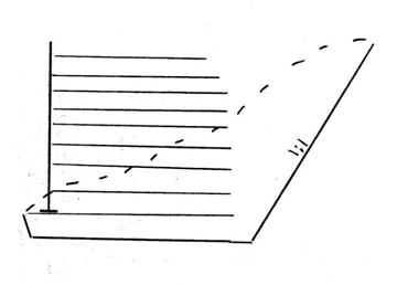
Figure 840.06.C.1 Excavation and Select Granular Backfill Areas
Figure 840.06.C.1 shows the wall excavation and embankment areas. All of the area below the dotted line is paid for under wall excavation. All the area between the wall and the 1 to 1 slope is filled with select granular backfill. The area below the leveling pad is filled with undercut material. Below is a field view of the same situation.
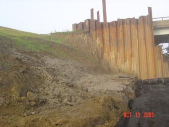
Figure 840.06.C.2 Area Behind the Wall
Foundation (840.06.D)
Preparation and Compaction
The MSE wall footprint area needs to be prepared in the leveling pad, soil reinforcement and select granular backfill areas.
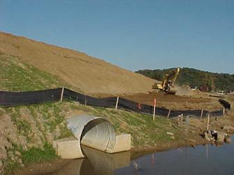
Figure 840.06.D.1 Foundation Preparation
Figure 840.06.D.1 above shows a track hoe excavating down to the MSE wall foundation. All organic matter, vegetation, slide debris and other unstable materials detailed as unsuitable in 703.16 needs to be removed. Once the unsuitable soil is removed, one foot outside of the foot print formed by the leveling pad and soil reinforcement needs to be compacted. The foundation needs to be compacted to meet the requirements of 203.07. If the foundation material is granular then the material needs to be compacted by one of the test section methods detailed in S-1015.
Once the foundation is compacted, then the foundation for the wall needs to be graded level for the full length and width of the leveling pad and the soil reinforcement.
Foundation Evaluation
Once the foundation is compacted the Department needs to evaluate the foundation. The plan design soils consultant needs to be contacted to evaluate the foundation. This can be paid for through continuing services during construction through the project design coordinator. The soils consultant will evaluate the soil conditions. In the design phase a bearing capacity and stability analysis was performed for the MSE wall based on the plan borings. This needs to be reevaluated based on the existing soil conditions during construction. The soils consultant will make a field visit to the site to determine if the foundation soils found during construction meet the soil conditions designed for in the plans. They will then write a report to the Department to give us there results. The Contractors pay depends on receiving this report so the Contractor will prompt the Department to make this evaluation.
The project should review the soils consultant report. The project should ensure that the excavated soils match the soil borings performed to design the wall. If the existing conditions do not match plan soil borings or there are any unusual problems with the report then contact the State Construction Geotechnical Engineer.
Undercut and Drainage
Drainage and the foundation conditions are important parameters of the MSE Wall system. Therefore many contracts will detail an undercut. If an undercut is in the plans then the foundation work detailed above should be performed on the foundation of the undercut.
Below is a sketch that details a standard undercut.
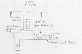
Figure 840.06.D.2 Standard Foundation Undercut
Once the foundation of the undercut is compacted then the drainage pipe is constructed. The plans will detail the pipe with a pay item. The pipe must be outletted. There will be at least 50 feet of outlet pipe in the plans to outlet the pipe. The project will have to look for an outlet if it is not detailed in the plans. Pipe, manholes and other items can be used as a drainage outlet.
If the pipe cannot be drained then move the pipe up to the outside of the wall until it can be drained. The dotted pipe in Figure 840.06.D.2 above the leveling pad represents this pipe. It is shown on the inside of the wall, But there is no need to put the drain on the inside of the wall. It can go on the outside of the wall also. The sand on the inside is free draining.
If the foundation or the foundation of the undercut cannot be compacted then an undercut depth may need to be determined. The following general procedure can be used to estimate the required depth of undercut.
Test pits can be used to further evaluate the foundation. For details on how to construct a test pit see Section 204. Construct two test pits, one on each side of the foundation of the wall or in the area of suspect soil conditions. Dig the test pit at least 3 feet deep. Take three penetrometer readings in each type of soil. If less than three soil types exists in the test pit then take readings in at least three different locations along the side walls of the test pits. Take a reading in the bottom of the test pit also. Use form CA-EW-3 to record the readings. All four sections on the form need to be filled out.
Once the readings are completed, average the values for each type of soil then average all four averaged values for the soil types. Once the average is obtained record the information on the Critical Layer or Design Layer on the bottom of the CA-EW-3.
The undercut depth can be obtained by using Subgrade Treatment Chart in section 204. Use the new construction line on the chart and the Critical Layer or Design Layer value previously calculated for the test pit. The determined undercut depth will result in a firm construction foundation.
Do not partially undercut the foundation. This would lead to differential settlement. If an undercut is required, then undercut the entire foundation.
Figure 840.06.D.3 below shows a five foot undercut operation. The replacement material in this case was a well graded blast rock. The material of choice for foundation replacement should be Item 203 Granular Material Type C. The upper portion should be chocked off with at least one foot of Item 203 Granular Material Type B. Geotextile Fabric Type D should be placed below the Granular Material Type C. This will prevent the piping of fines from the top and the bottom of the Granular Material Type C.
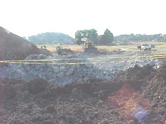
Figure 840.06.D.3 Replacing the Foundation
Leveling Pad Construction (840.06.E)
Once the foundation is compacted and prepared, a 2-foot wide and 6-inch thick un-reinforced concrete pad is constructed. The purpose of this pad is to serve as a guide for the wall panel erection. This leveling pad is not intended to provide significant structural foundation support in the final configuration of the wall. But there is significant construction panel loading on the leveling pad. Therefore it must be properly constructed and on a firm foundation in order to minimize potential wall movements during the construction of the wall.
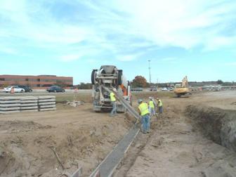
Figure 840.06.E.1 Leveling Pad Construction
The leveling pad is important to the construction of the wall because the leveling pad sets the horizontal and vertical alignment of the wall. It must be in the correct horizontal position, level and at the correct grade.
Figure 840.06.E.2 Accurate Leveling Pad Construction is Important
If the final wall is not level, the panels will bind against each other causing spalling of the edges and corners. If the wall is not started correctly, the finished product is seldom satisfactory.
No more than 2 shims (each 3/16 inch thick) should be required to level the panels on the leveling pad. If level cannot be obtained with two shims then the leveling pad and the bottom of the panels needs to be checked.
Figure 840.06.E.3 Improper Shimming
Under no circumstances are bearing pads allowed on the leveling pad. Using bearing pads can create point loads on the panels and allow for movement of the panels during construction.
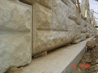
Figure 840.06.E.4 Bearing Pads are Not Allowed on the Leveling Pad
Care must be taken to ensure the leaving pad is correctly aligned. The leveling pad is 24 inches wide to allow for some alignment errors and inconsistencies such as happens when going around corners and curves. In addition, the wider leveling pad will supply more support during construction.
Do not allow any overhanging of the panels off the leveling pad. If this happens, stop the construction and investigate the problem. If needed, reconstruct the leveling pad.
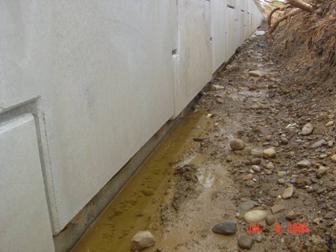
Figure 840.06.E.5 Improper Overhang
Leveling pads that change in elevation have special challenges in design and construction. Figure 840.06.E.6 below details this challenge. This figure is a general step up figure with some of the dimensions changing in the new SS-840.
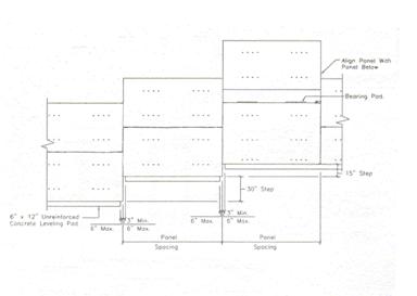
Figure 840.06.E.6 Change in Leveling Pad Elevation
The challenge is to arrange the leveling pad and panels so that when this elevation change occurs the panel is almost fully supported by the leveling pads. Multiple elevation changes are even more difficult to construct. In all cases, a six inch maximum overhang along the wall is allowed. The minimum distance being around 3 inches.
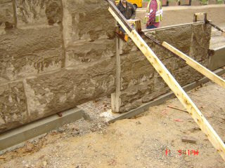
Figure 840.06.E.7 Acceptable if Less than 6 inch Overhang
The concrete leveling pad must cure for at least 12 hours before wall panels can be placed.
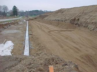
Figure 840.06.E.8 Finished Concrete Leveling Pad
Wall Panels Types and Parts (840.04)
Wall panels come in many shapes and sizes. The most common are the square, rectangular or cruciform. They can be custom built into any configuration that will fit together. The front face can have any type of finish, shape, texture or other surface treatments that can be formed.
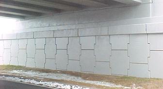
Figure 840.04.A Reinforced Earth Panels
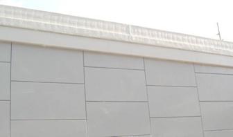
Figure 840.04.B Rectangular Panels
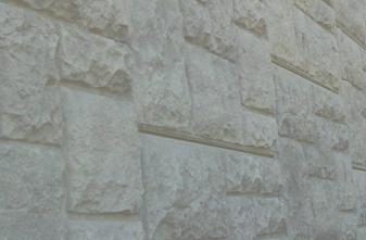
Figure 840.04.C Textured Finish Panels
Corner Panels
Corner panels provide a good connection between the two walls and act like slip joints for the wall allowing differential movement between the two walls.
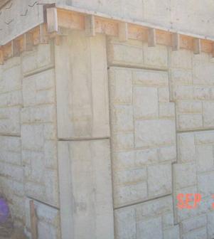
Figure 840.04.D Corner Panels
Slip Joints
Typical a slip joint is used to handle large differential vertical movement of the wall. There are two in the figure below one on each side of the corner section.
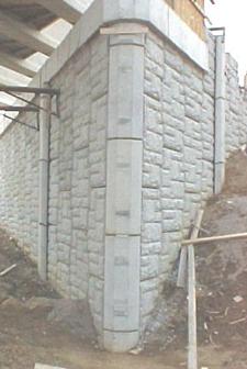
Figure 840.04.E Corner (front) and Slip Joints (One on Each Side)
Panel Storage (840.05)
Panels should be stored flat and on spacers or dunnage. Spacers are typically sent by supplier on pallets of panels. Spacers protect the galvanized soil reinforcement connections from being bent or damaged by other panels. Panel faces should be kept away from areas that are muddy to prevent staining of the face of the panel. The project should ensure that panels don’t have spalling or cracking upon delivery to the site.
Correct storage is shown in Figure 840.05.A. Note that the dunnage height is more than the soil reinforcement connections to minimize damage.
Figure 840.05.A Proper Panel Storage with Dunnage
Figure 840.05.B is an example of improperly stored panels. The panels in this case can get chipped or cracked.
Figure 840.05.B Improper Panel Storage
The soil reinforcement connections can get bent also.
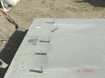
Figure 840.05.C Damaged Tabs
Panel Inspection (840.05)
Panel Dimensions
When the panels first arrive at the project, the panel documentation needs to be checked. The panels come in with a TE-24. The documentation required with this TE-24 are a record of final inspection of all precast components and the measurements of the tolerances, strength and dimensions of all panels. As one final check the dimensions need to be randomly checked at the project. The shipment paperwork, shop drawings and the actual panel dimensions need to be compared to ensure that issues are found in a timely manner. The earlier in the process that these problems are found the better off we are in terms of correcting the issues. Some of the panel items to pay particular attention to are:
1. Length, Width and Thickness
2. Squareness
3. Finish
Physical measurements of the panels are required. The project should use a tape and carpenters square to check the above. All of these dimensions have an effect on the Contractor’s ability to construct the wall within the specification tolerances.
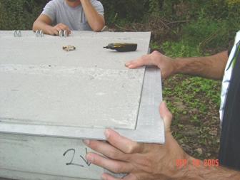
Figure 840.05.D Checking the Squareness of the Panel
Damage to the Galvanized Soil Reinforcement Connections
If the soil reinforcement connections are damaged to the point that it inhibits the soil reinforcement from being attached then the panel needs to be rejected. Many times the connection is filled with residual cement or concrete that does not allow the soil reinforcement to be connected. If this is the case then have the Contractor clean out the connections. Do not cut the soil reinforcements.
If the connections are bent more than 15 degrees from perpendicular then the panel needs to be rejected. When bent beyond 15 degrees, the galvanizing is compromised and cannot be repaired.
Damage to the Panels
The panels also need to be inspected for damage. Panels can be damaged almost anywhere in the manufacturing or construction process. Many of the chips and cracks are caused by poor handling. Chips or spalls can be prevented by using nylon straps in the handling process. Cracks can be avoided by using care in the handling process. There is a list of defects and damages in 840.05.H that are sufficient reason for rejecting a panel. Depending on the severity of the damage, the Contractor may propose a repair.
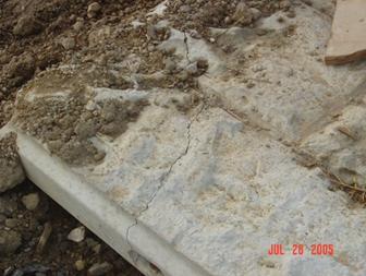
Figure 840.05.E Rejected Cracked Panel
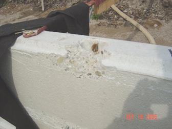
Figure 840.05.F Rejected Lifting Spall
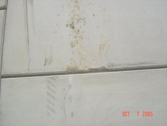
Figure 840.05.G Repairable Lifting Strap Spalling
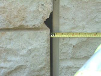
Figure 840.05.H Repairable Handling Spalls
Wall Construction (840.06.G)
Panel Identification
At this point, we have constructed the foundation, added drainage, checked the materials and constructed the leveling pad.
There is one last step we need to perform before we construct the wall; the wall and shop drawings must be checked to ensure that the correct panels are being used in the correct location along the wall. Depending on the wall height, the panel shape or design, the number of soil reinforcement connections on the back of the panel may vary. The panels with the most connections will typically be in the lower panels of the wall. In the upper portions of the wall, the number of connections may be less. It is important that the panels are used in their proper position. Below is a typical shop drawing showing the panel organization.
Figure 840.06.G.1 Typical Panel Erection Shop Drawing
The erection drawings have a numerical code on each panel that depicts its position in the wall. In the above shop drawing, the letter “A” denotes full height panels in the first row and the subsequent rows until the shape changes as the panel is just below the coping. The letter “B” denotes half height panels in the first row. The codes HX, F11, L11, KX, K, E, EX, HJJ, KJJ, LJJ, DJJ and EJJ denote panels just below the coping. (Note combination of letters) R or L will be used to denote the right or left side of the wall. A number that follows the letters denotes the number of tie strips required for the panels. Below is a code that details the panel letter and numerical system.
Figure 840.06.G.2 Code for Panel Placement (Reinforced Earth)
The code that is detailed above is for Reinforced Earth walls. The code for other wall systems will be different, and the code for a particular wall system may change at any time. The codes are marked on the back of the panels for easy reference during construction. Below is a photo of the marking on the back of a panel.
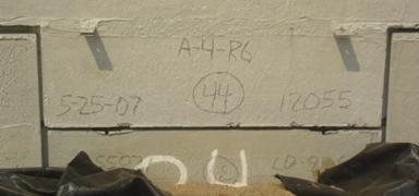
Figure 840.06.G.3 Actual Panel Markings
The above markings show piece A has 3 tie strips and is on the right side of the wall. Other required markings include date of manufacturing, production lot number and the precaster’s and accredited manufacturer’s inspection and acceptance marks.
Placing the Panels
Picking up the panels is an important aspect of the construction procedure. If the panels are not properly picked up spalling or cracking can occur. The figure below shows the correct method of picking up the panels. The crane lifts the panel such that no concrete to concrete contact occurs.
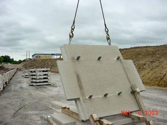
Figure 840.06.G.4 Picking up the Panels
The correct placement of the first row or two of panels is very important. When the panel construction is not started correctly the finished product is rarely satisfactory.
In the figure below, a chalk line is placed on the leveling pad to properly align the panels along the leveling pad. Sometimes a 2×4 is used to align the panels. Adjust the alignment using a crowbar as shown below. At this point the panel is still supported by the crane.
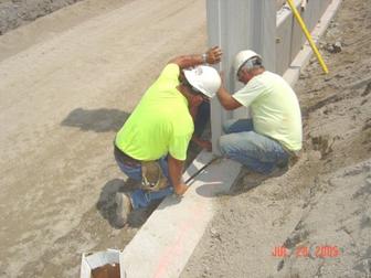
Figure 840.06.G.5 Proper Placement
As one last check of the horizontal alignment, the panel to panel horizontal offset needs to be checked. Use a straight edge across the panel horizontal joints to ensure that the panel to panel horizontal offset does not exceed a ½ inch.
The first row may be composed of both half and full height panels. A photo of full and half height panels is shown below. The panels need to be in proper alignment and level.
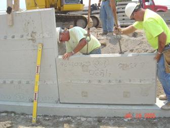
Figure 840.06.G.6 Half Height Panels
Horizontal Leveling
Once the panel is placed on the leveling pad the panel needs to be leveled horizontally. A 6-foot level rod is placed on the top surface of the panel to determine if it is level.
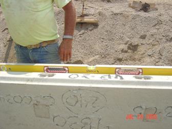
Figure 840.06.G.7 Proper Horizontal Leveling
If it is not, shims are placed under the panel in order to make the panel level. Galvanized metal washers or rubber shims are allowed. A maximum 3/8 of an inch in total shim height at any location is allowed. If more shims are required then the leveling pad is not level or the panel bottoms are not flat. In either case, the issue is the Contractor’s responsibility to resolve.
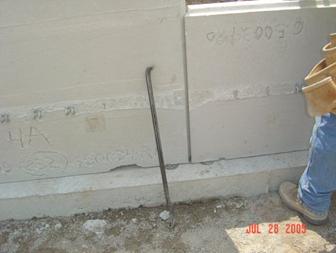
Figure 840.06.G.8 Metal Shims to Level the Panels
Horizontal Joint Spacing
Without the correct joint spacing, panel corners will crack and spall with the wall settlement. Spacing blocks must be used. As the panels are placed together, the ¾ inch spacers are placed in the joints. The panels are maneuvered so that there is contact between both panels and the joint spacer. The required joint spacing is ¾ of an inch plus or minus ¼ of an inch. If this spacing cannot be achieved, the Contractor is required to submit an action plan to correct the problem. The spacer is shown in the figure below. If the panel is moved during the joint spacing adjustment then the horizontal leveling should be checked again.
Leave the horizontal spacers in until ½ panel height is filled with backfill.
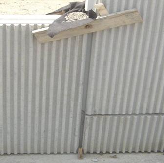
Figure 840.06.G.9 Wooden Joint Spacers
Vertical Alignment
The panels need to be set with a backward batter toward the inside of the wall. The typical batter is about 1/8 inch per foot of panel height or about ½ to 1 inch per panel. The act of compacting the backfill behind the wall pushes the panel outward so the panel will be vertical once the fill is placed against it. The amount of batter is adjusted for the site conditions such as backfill properties; the finer sand may require a more batter. If a fine graded material, such as foundry sand, is used then it may require a one inch batter. A well-graded crushed limestone may require a half an inch batter.
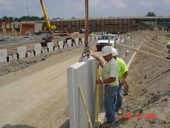
Figure 840.06.G.10 Batter Check
A level with a batter spacer is placed on the outside or inside of the wall. Use the outside of the wall unless textured. The batter spacer can be used on the top or bottom of the level. If the level is used on the outside of the wall, the batter spacer is used on the top of the level. If the level is used on the inside of the wall the spacer is used on the bottom of the level. The spacer is usually duct taped on to the level at a thickness of the batter. In the figure below, it shows the batter spacer being used on the inside of the wall.
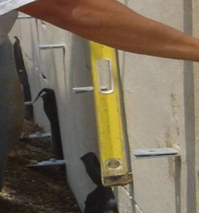
Figure 840.06.G.11 Vertical Leveling Spacer on the Inside of the Wall
The level can also be used on the outside of the wall as shown below.
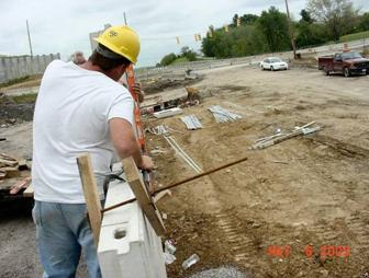
Figure 840.06.G.12 Vertical Batter on the Outside of the Wall
Vertical and horizontal alignments and joint spacing needs to be checked one last time prior to temporarily locking the panel in place. For the entire time the horizontal leveling, joint spacing and vertical alignment is being adjusted, the panel is still suspended from the crane so that the panel is not damaged.
Triangular Wedges and Wood Blocks
Wooden triangular wedges are used to lock the panel into vertical alignment once the wall is battered with the level. The wedges are shown below on the leveling pad.
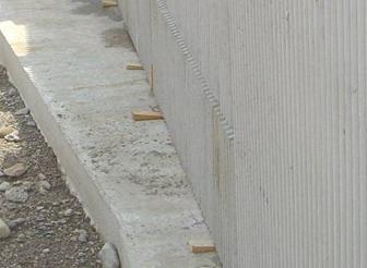
Figure 840.06.G.13 Wooden Wedges for Vertical Alignment
No more than three levels or rows of the wooden wedges should be placed in the wall without removing the lower row. If more than three levels of wedges are used they may become bound in the wall making them very difficult to remove and can cause the panel to spall.
Wooden clamps are then used to hold the panels together. Wooden clamps are two pieces of wood held together with a long bolt. The bolt is tightened to hold the panels together.
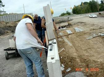
Figure 840.06.G.14 Wooden Clamps
Triangular wedges are also used in combination with the clamps to secure the panels as shown in the figure below.
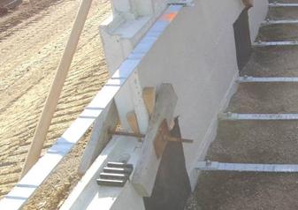
Figure 840.06.G.15 Triangular Wedges and Wooden Clamps
External bracing is required for the first row of panels to maintain stability and alignment. Typical bracing is shown below.
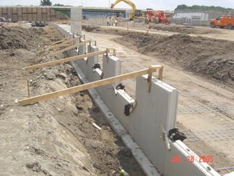
Figure 840.06.G.16 Proper Bracing
At this point the geotextile fabric and the select granular backfill is placed to the height of the wooden clamps. These steps will be described in detail later.
When panels are placed on one another, a horizontal bearing pad is used to separate the panels. A minimum of two bearing pads are used. The horizontal joint should be ¾ inch at this point. Some Accredited Wall Systems may supply thicker bearing pads. This is anticipation of the bearing pads deflecting under the load of the wall. Check the accepted wall shop drawings to ensure that the thicker pads are allowed.
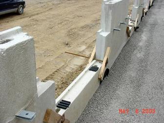
Figure 840.06.G.17 Bearing Pads on the Second Row
Subsequent panel rows are placed betweens panels that were previously placed. The ability to properly space and align these rows relies on the proper placement of the lower rows. All of the error produced by the lower rows is propagated upward and is difficult to correct. The same leveling, joint spacing, vertical and horizontal alignment also applies to all the rows.
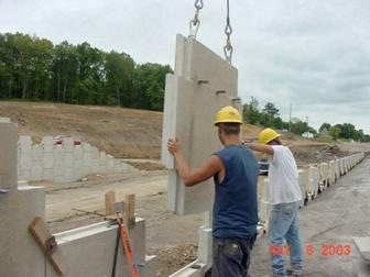
Figure 840.06.G.18 Panel Placement
Panel to panel vertical offset needs to be checked as soon as the next row of panels is placed. Use a straight edge across the vertical joints to ensure that the offset between panels is less than a ½ inch.
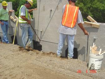
Figure 840.06.G.19 Second Row of Panels Placed
The process starts all over again as crow bars are used to align the next row of panels.
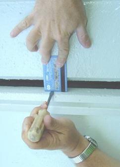
Figure 840.06.G.20 An Existing Joint Offset Problem
Alignments need to be checked periodically to ensure proper alignment. This will ensure that problems are spotted early and corrections can be made before the panels get too far out of alignment.
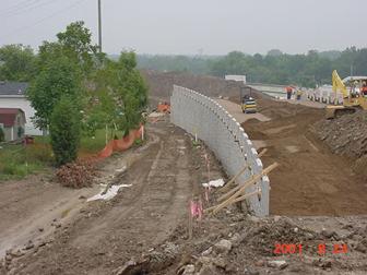
Figure 840.06.G.21 Wall Alignment
As stated before, the panels are battered back so that the fill placement can move them forward into a vertical position. After the fill is placed, check the vertical position of the wall. After the third row of panels are placed, use a plumb bob to check the vertical alignment. Hold the plumb bob at the top of the panel and measure the out of plumbness as shown below.
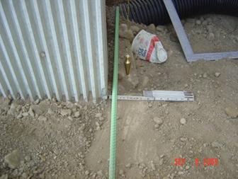
Figure 840.06.G.22 Checking Vertical Alignment with a Plumb Bob
The tolerance is ½ of an inch in 10 feet. By using a 10-foot straight edge and a level or a plumb bob this tolerance can be measured. At no point along the straight edge can any portion of the panels be more than an inch away from the string or straight edge.
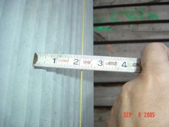
Figure 840.06.G.23 Measure from the Wall to the String (Out of Plumb Here)
A summary of the wall erection tolerances are listed below:
1. Vertical Tolerance: ½ inch overall and 1 inch at any point
Use a 10-foot straight edge
2. Horizontal Tolerance: ½ inch overall and ½ inch at any point
Use a 10-foot straight edge
3. Panel to Panel Tolerance: ½ inch horizontal and vertical
Use a 6-foot straight edge
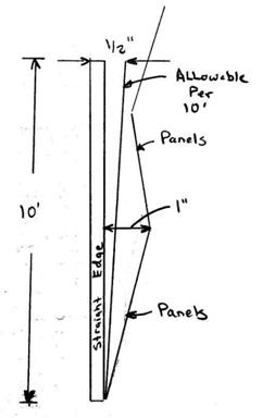
Figure 840.06.G.24 Panel Tolerances
Filter Fabric Placement and Inspection
Filter fabric is placed across the joints so that the granular backfill does not leak through the joints to the outside of the wall. The minimum lap on each side of the joint is one foot on each side of the joint and one foot along any cut piece of fabric along the joint. These requirements apply to horizontal and vertical joints.
The fabric is cut in lengths to cover the horizontal and vertical joints. Once the fabric is cut, the fabric is laid on a flat surface. An adhesive is used to hold the filter fabric in place until the select granular backfill is placed over the joints. A thick bead of the adhesive approximately ½ an inch in diameter is applied around the entire perimeter of the fabric about two inches from the edges of the fabric. See the figure below.
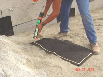
Figure 840.06.G.25 Correct Application of the Adhesive
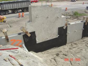
Figure 840.06.G.26 Fabric Completely Covering the Joints
Once adhesive is applied to the fabric it is immediately placed on the wall. Ensure that the fabric is placed on the wall before the adhesive dries. The fabric needs to fully engage the wall at all locations to ensure that the sand does not leak through the joints.
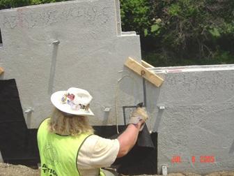
Figure 840.06.G.27 Wrong Application of the Adhesive on the Wall
A shown above, randomly placing adhesive on the wall does not ensure that the joint is properly sealed. More adhesive is not necessarily good. Correctly applied adhesive and the appropriate placement of the fabric is the solution.
In the past, some projects have only glued the top portion of the fabric applied to a horizontal joint. This method should be discontinued and not be allowed.
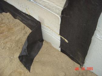
Figure 840.06.G.28 Partial Gluing (Do not allow this)
Small tears or wrinkles in the fabric can cause leaking of the sand. Any leaking of the sand through the joints is not tolerable. Leaking sand is like a leaky water pipe; it never gets better with time, it only gets worse.
Once the fabric and the backfill are placed, the project should go around to the front of the wall to inspect the joint spacing and the fabric’s ability to hold the sand behind the wall. Take a flash light and inspect the joints. Look to see if the fabric is in place and holding the sand back.
Look for deposits of sand in the horizontal and vertical joints as shown below.
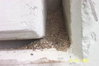
Figure 840.06.G.29 Sand in the Joints on the Outside of the Panels
Sand deposits may be caused by sand falling over the wall during construction or the sand is leaking through the joints. By carefully inspecting the joints, the source of the sand deposit will be found. In the figure below, the sand is leaking out of the joints and being deposited on the ground.
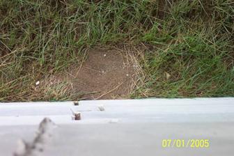
Figure 840.06.G.30 Sand Falling from Several Joints
After further inspection of the wall from behind, it was found that the fabric was not placed in the upper portion of the MSE Wall. This project was about three years old at the time of the inspection. A thorough inspection during the construction of the wall would have prevented this maintenance problem.
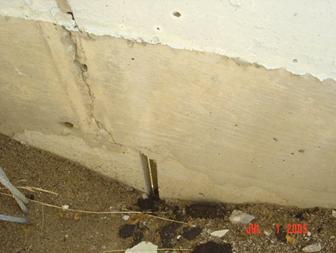
Figure 840.06.G.31 No Fabric Placed Behind the Wall
Below is a photo of a wall taken shortly after construction. As you can see there are sand deposits at the bottom of the slip joints. In this case, the fabric was either not placed or improperly placed.
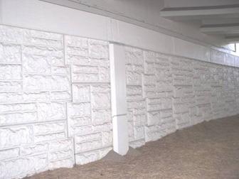
Figure 840.06.G.32 Sand Piles around Slip Joints
In the figure below, looking behind the wall at a typical slip joint during construction, you can see that the fabric has to go around a bend. Careful construction in this location is required. When placing fabric around corners or obstructions leave the fabric loose so that it does not tear during the placement of the backfill in the corner.
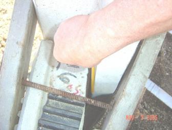
Figure 840.06.G.33 Fabric Placement around a Slip Joint
There are a lot of other items of work that obstruct the proper placement of the fabric in this situation. In the figure below, there are the reinforcing steel, wooden clamps, and a settlement plate that the fabric needs to go around. There is ample opportunity for sand to leak around the fabric if we are not careful.
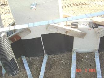
Figure 840.06.G.34 Obstructions near a Slip Joint
The joint spacing needs to be reexamined in the front of the wall. We have previously checked and recorded the joint spacing when the panels were constructed. There may be cases where after the wall is constructed the joint spacing is wider than the allowable ¾ of an inch plus ¼ of an inch.
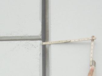
Figure 840.06.G.35 Wide Joint and Exposed Fabric
The joint gap in the above figure is almost 1¾ of an inch. The gap is wider than the panel’s ship lap, thereby exposing the fabric. The width of the ship lap is about 1½ inches. In the above case, the Contractor needs to be instructed to place expansive foam and caulk to the joint to prevent the fabric being exposed to sunlight.
Sunlight can cause the fabric to deteriorate with time, whether it is direct or indirect. Therefore, a flashlight is used to ensure that sunlight exposure to the fabric is minimized. A flashlight is held perpendicular to the joints about six inches away from the joint. Such a flashlight test is shown in the figure below.
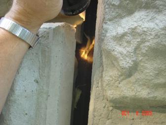
Figure 840.06.G.36 Flashlight Test
If the light from the flashlight can be seen on the fabric, then the joint needs to be sealed. Expanding foam and caulk is used to cover the fabric.
There have been instances where, after the wall has been constructed, the fabric is being destroyed during the water jetting operation. The water jetting is used to clean the panels prior to sealing. Therefore, examine the joints after the sealing operation.
As a final note on the wall construction, continue to monitor the wall throughout the duration of the project. The wall is designed and constructed to tolerate movement. But too much movement is detrimental to the wall and the structural items around the wall.
Select Granular Backfill Material and Placement (840.06.I)
Material
The granular backfill materials have special requirements that are not normally associated with granular material in other items of work. There are material requirements such as pH, resistivity, chloride and sulfate levels. These requirements minimize the corrosion of the metal soil reinforcement. The project and district test lab need to review and evaluate the test data for these requirements. Ensure that the test results meet the specification requirements and that the correct tests were taken on the materials. If the backfill material does not meet these requirements then there is a high probability that the metal soil reinforcement will prematurely corrode and the life of the MSE Wall will be shortened.
Another requirement is the internal angle of friction. The internal angle of friction is critical to the design of the wall. The wall design and the factor of safety are sensitive to numerical value of the friction angle. The factor of safety can change dramatically with only a few degree friction angle change. The design friction angle is 34 degrees. The test ensures that the design assumption is valid.
The specification allows the use of granular material type 2 which is old Item 310 material. It can be a very fine sand or a coarse 304 type material. Since economics drives the material choice, the vast majority of the time sand is used.
The specification also allows the use of Item 304 material. This material is a well graded and very stable material.
It is a requirement to use the Item 304 material for the first 3 feet of backfill behind the wall. This is a stronger material and is more resistant to the influences of water. After the first 3 feet are placed, the sand or the 304 may be used.
Select Granular Backfill Placement and Compaction
The below placement and compaction procedures were developed to produce uniform compaction of the select granular backfill (SGB). Uniform placement and compaction of this material is essential in order to keep uniform pressure against wall as it is constructed. Unnecessary compaction or non-uniform compaction of this material can create bulges in the wall or loose areas in the backfill behind the wall. This procedure is to be followed all the way to the top of the wall.
On the initial row of panels (and only the initial row of panels) the backfill is not placed against the panel until the first layer of soil reinforcement has been connected and the initial layer of backfill is placed and compacted on top of the soil reinforcement. This is to keep the bottom of the panels from “kicking out”. If the SGB cannot be compacted effectively below the first row of soil reinforcement (because some manufacturers may have mesh that we cannot compact through) then the wall supplier will need to design a kicker to prevent the wall from kicking out at the bottom.

Figure 840.06.I.1 Backfilling for the First Panel Only
Once the backfill is placed and compacted to the elevation of the first layer of soil reinforcement as shown in Figure 840.06.I.1, the soil reinforcement is connected. Then the next loose lift is placed on top of the soil reinforcement 3 feet away from the wall. The material is then leveled by moving it parallel to the wall and windrowing the material toward the soil reinforcement ends and away from the wall. See Figure 840.06.I.2 for the spreading operation details. This SGB material 3 feet away from the wall is then compacted in the same way as it was placed.
Figure 840.06.I.2 Procedure for SGB Placement and Compaction
Once this is completed, then the void is filled and compacted next to the wall to the elevation of the soil reinforcement. The material void left above the soil reinforcement is then placed and compacted. Place and compact this inner most 3 feet as detailed in Figure 840.06.I.3. Within three feet of the wall, the SGB is compacted with six passes of a mechanical tamper or vibratory plate compactor. The compaction equipment should have a centrifugal force between ½ and 2 tons.
Figure 840.06.I.3 Place and Compact the SGB Next to the Facing Panels
Use the procedure detailed in Figures 840.06.I.2 and 840.06.I.3 for the SGB placement and compaction procedure for the remaining sections of wall.
The SGB is placed in maximum 8-inch loose lifts. It may be helpful to mark the lift thicknesses on the back side of the wall panels. The action of moving the SGB parallel to the wall and windrowing or compacting the material toward the reinforcement ends and away from the wall takes out the slack in the reinforcement and locks the reinforcement and the panels in position.
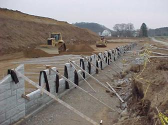
Figure 840.06.I.4 Improper Spreading Technique
(From back to front is improper)
Any slack in the reinforcement should be removed to avoid excessive panel movement. With geogrid soil reinforcement some tension needs to be applied to the reinforcement by means of a kicker tension device or a rod during this backfill placement.
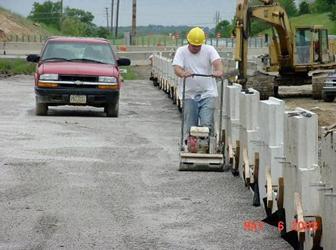
Figure 840.06.I.5 Final Compaction Operation Next to the Wall
Consistent placement and compaction of SGB are one of the keys to a good performing MSE Wall.
Compaction Testing of the Select Granular Backfill
No compaction testing is performed on the SGB within three feet of the wall. For the SGB more than three feet from the wall facing panels, smooth-drum vibratory rollers weighting between 6 and 10 tons are required to compact the material. The compaction testing is performed according to Supplements 1015 and 878.
Supplement 878 details the general inspection and compaction testing requirements when these services are hired through the Contractor. All of the inspection and compaction procedures that are required for ODOT inspection personnel are required for the Contractor’s personnel under S-878. A trained compaction and inspection person is required under this specification. All of the Department inspection and compaction forms are to be used.
Supplement 1015 details the inspection and compaction procedures to be employed during the work.
At the beginning of the work, a test section is constructed to determine the density requirements for the select granular backfill. The moisture requirements are determined by using the moisture density curve for the Method A test section. For a Method B test section, the moisture requirements are determined by constructing several test sections at different moisture contents. For determining which test section that is used see section S-1015.
The select granular material is compacted between three percent below and optimum moisture content. If additional water is required after spreading the material then water must be added to meet these requirements. The moisture content of the select granular backfill material prior to and during compaction is to be uniformly distributed throughout each layer of material. If watering is required after spreading then the project should dig up the material to ensure that this requirement is met.
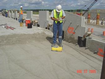
Figure 840.06.I.6 Taking a Compaction Tests
Once the moisture content is correct, the test section is constructed to determine the density requirements for the remaining areas of the select granular backfill. This test section is approximately 40 square yards. This test section is compacted until a maximum density is achieved. The number of passes and the maximum density is used in the remainder of the work. A minimum of 98 percent of the maximum density is required. A new test section should be constructed if the compaction tests are not close to the maximum value by using the same number of passes, if the material or foundation conditions change.
In the figure below, the compaction started from 3 away from the wall and is proceeding to the back of the soil reinforcement. In the background, the area within three feet from the wall is compacted after the roller compaction is complete. This procedure was detailed in the previous section.
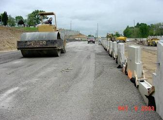
Figure 840.06.I.7 Smooth-drum Vibratory Compaction Equipment
Maintenance and Drainage (840.06.F)
At the end of each day’s operation, the Contractor is to shape the last layer of backfill to allow rainwater to runoff away from the wall face. The drainage system is under or in front of the wall. This will permit the water to dissipate from the system. The SGB of the wall can be drained laterally to dissipate out to the sides. Drainage problems can develop similar to the figure below.
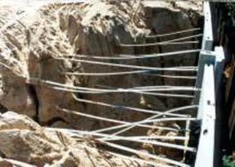
Figure 840.06.F.1 Washout around the Soil Reinforcement
Water ponding in front of the wall has been a problem is the past. In the figure below, you can see the ponding of the water in front of the wall. This is not acceptable.
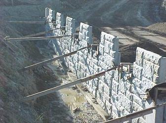
Figure 840.06.F.2 Water Ponding in Front of the Wall
It is required to pump the water out of this area immediately after the water is ponded. In addition, once the wall is erected up to the ground elevation, this void is filled with embankment material. This will further stabilize the wall.
If water is ponding behind the wall during construction as shown below:
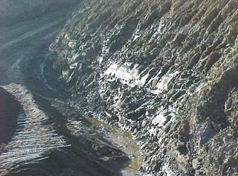
Figure 840.06.F.3 Water Ponding Behind the Wall
Then collect the water by using a drainage curtain as detailed below:
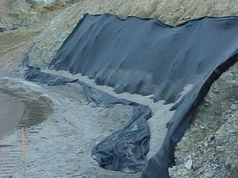
Figure 840.06.F.4 Drainage Blanket
Side slope erosion has been a problem in the past. One solution has been to construct 2 feet of embankment on the side slopes. This will bury the highly erosive select granular material and erosion can be minimized.
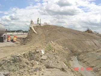
Figure 840.06.F.5 Protection of the Erosive Side Slopes with Embankment
Soil Reinforcement Placement (840.06.H)
Soil Reinforcement Storage
The soil reinforcement is used to tie the wall to the soil. Like the panels, the soil reinforcement should be stored on dunnage and carefully handled to prevent damage. Damage may include bending of the metallic reinforcement and damaging the galvanization. The geogrid soil reinforcement should not be torn, cut, left in the sun or otherwise damaged.
No equipment should be allowed to run directly on the reinforcement.
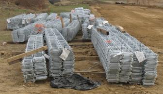
Figure 840.06.H.1 Reinforcement Storage on Dunnage
The project should check for required length and gauge of steel reinforcement. Check the condition of steel reinforcement upon delivery to the site. Below is a typical plan view of the soil reinforcement on a project. The length of the reinforcement from the wall is directly proportionate to the height of the wall. The wall height below is the highest in the center and the length of the reinforcing is the longest. The length of the reinforcing cannot change from the bottom to the top of the wall. It can only change along the wall due to changes in the height or design changes.
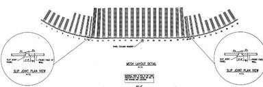
Figure 840.06.H.2 Typical Reinforcement Layout
Below is a detail of a cross sectional view of the soil reinforcement in the same wall. Notice the soil reinforcement connection to the wall and regular intervals. The length of the reinforcing is the same from the bottom of the wall to the top of the wall. Many of these walls are placed below an abutment as detailed below.
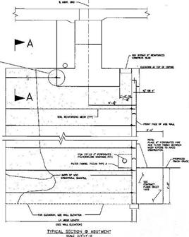
Figure 840.06.H.3 Cross Section of the Soil Reinforcement Layout
Below in the following details are the reinforcing mesh codes for a Foster wall. These are the codes that were used on past projects. For Foster walls, the reinforcing mesh will change frequently. The project should familiarize themselves with the codes on the shop drawings and ensure that the correct mesh types are placed in the proper location.
In the figure below, it details the wire mesh codes. Careful review of these keys is required by the project.
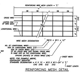
Figure 840.06.H.4 Reinforcing Mesh Details
In the detail below, it shows a sample of how the reinforcing mesh is laid out as it relates to the panels. The panels are numbered in the example and the type of reinforcing mesh is detailed beside the panel type.
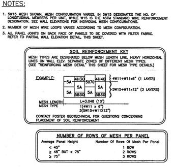
Figure 840.06.H.5 Reinforcing Panel and Reinforcing Key
Typically, the reinforcement is placed perpendicular to the wall face. Any slack in the reinforcement should be removed. The geogrid soil reinforcement should have some tension placed in the reinforcement. By using the placement and compaction procedure detailed in the previous section it will keep the tension in the soil reinforcement.
Once the fill is compacted to the elevation of the soil reinforcement, the soil reinforcement can be attached to the facing panels and placed perpendicular to the face of the wall on top of the compacted material.
Connections
Connecting the soil reinforcing to the wall is relatively simple operation. There are three connections that will be detailed below.
Reinforced Earth Connection
A Reinforced Earth Wall’s connections and soil reinforcement consist of galvanized strips, tabs manufactured in the wall and nuts and bolts to connect them. There are tabs with holes that stick out of the wall about 3 inches. The tabs have a top and bottom and go around the strips when they are connected.
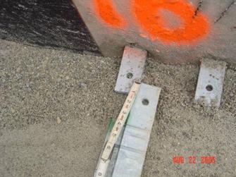
Figure 840.06.H.6 Reinforced Earth Connections and Strips
At times there is concrete inside the tabs that makes it difficult to place the strips inside the tabs. The concrete needs to be cleaned out to line up the holes. Many times the Contractor will cut the strips instead of cleaning out the concrete. Do not allow the strips to be cut in the field. This can reduce the strength of the connection. Also, the galvanizing of the strip will be compromised and the strip will prematurely rust.
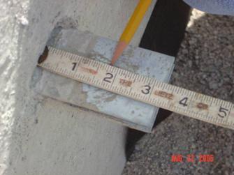
Figure 840.06.H.7 Tabs for Reinforced Earth Connections
Once the holes are lined up, the bolt is inserted from the bottom up and the nut is tightened. By placing the bolt from the bottom, it is easy to see if the nut has been placed on the connection.
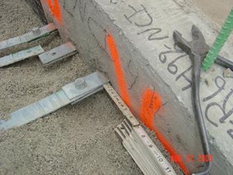
Figure 840.06.H.8 Bolted Reinforced Earth Connection
Below are multiple strips connected to the wall for a Reinforced Earth Wall. Leaving the select granular backfill lower at the tabs is acceptable. The select granular backfill needs to be as close to the strips as possible for all wall types.
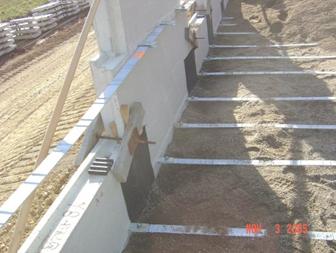
Figure 840.06.H.9 Reinforced Earth Multiple Connections to the Wall
Wire Mesh Connection
The connection for steel wire mesh soil reinforcement consists of hooked eyelets in the panels and reinforcing mesh with two transverse bars at the end. The end of the wire mesh is laid with the two transverse bars resting on top of the hooked eyelets. A rod is inserted through the eyelets, locking the mesh into place, as shown below. Wooden wedges are then hammered between the wall and the mesh to put the eyelets in full contact with the mesh and the soil reinforcement in tension.
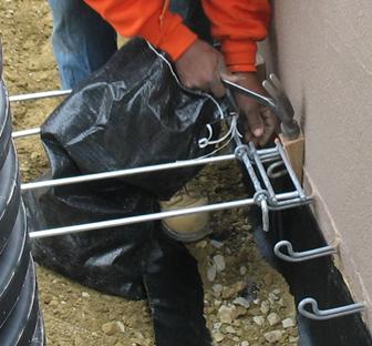
Figure 840.06.H.10 Wire Mesh Type Connection
Below is a typical layout of the soil reinforcement of a wire mesh wall.
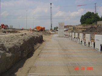
Figure 840.06.H.11 Mesh Steel Laid Out
Geogrid Soil Reinforcement Connection
The connection for geogrid soil reinforcement consists of short sections of geogrid cast into the panels and a plastic bodkin bar. The ribs of the geogrid soil reinforcement are meshed with the short sections of geogrid that are cast into the panels. Then the plastic bodkin is weaved between the two sets of ribs and the soil reinforcement is pulled tight. The completed connection is shown below.
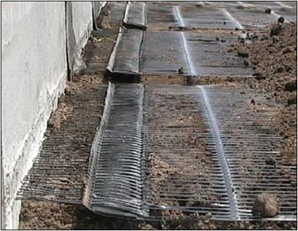
Figure 840.06.H.12 Geogrid Soil Reinforcement Connection
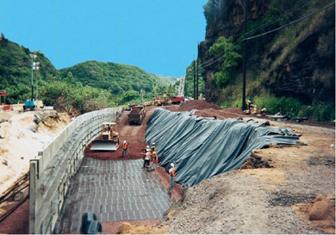
Figure 840.06.H.13 Overview of Geogrid Soil Reinforcement
Obstructions
There are times when the soil reinforcements have to go around obstructions. It is not acceptable to just simply leave out the reinforcement at that location. This would create a weak location along the wall.
At horizontal obstructions, such as pipes, the reinforcement should not be angled more than 15 degrees up or down. All situations that exceed 15 degrees must be detailed on the accepted shop drawings or acceptable to the Office of Structural Engineering. The soil reinforcement must have a four inch clearance above or below the obstruction. Also, when clearing horizontal obstructions, the reinforcement should be smoothly curved around the obstruction. The reinforcement should not be kinked at any time.
The detail below shows a horizontal obstruction lower than the soil reinforcing and connection.
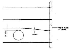
Figure 840.06.H.14 Soil Reinforcement going over a Horizontal Obstruction
The detail below shows a horizontal obstruction higher than the soil reinforcing and connection.
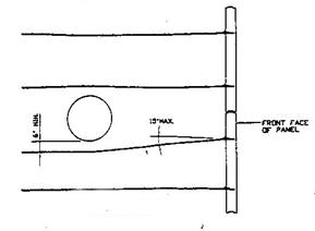
Figure 840.06.H.15 Soil Reinforcement going under a Horizontal Obstruction
The photo below shows the soil reinforcement going under a storm sewer line.
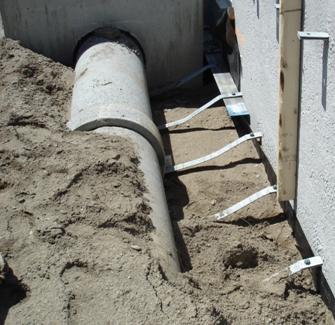
Figure 840.06.H.16 Soil Reinforcement going under a Storm Sewer Line
At vertical obstructions, such as piles or catch basins, if the reinforcement must be splayed more than 15 degrees from horizontal the accepted shop drawings should detail a modification. All situations that exceed 15 degrees must be detailed on the accepted shop drawings or acceptable to the Office of Structural Engineering. It may require additional reinforcement length to meet design.
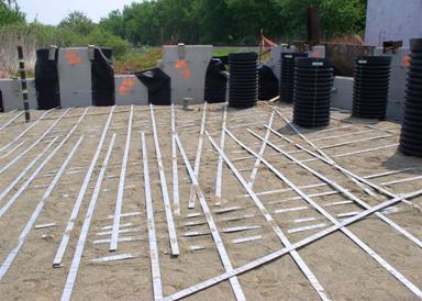
Figure 840.06.H.17 Soil Reinforcement Splayed Around Piles
In the detail below, the soil reinforcement was designed around the inlet by using a galvanized angle in front of the inlet and keeping the reinforcing steel perpendicular to the wall. Again this would have to be detailed on the acceptable shop drawings.
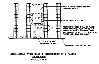
Figure 840.06.H.18 Typical Details for Obstructions
Below is a photo of the galvanized angle in front of the catch basin to allow the soil reinforcement to be placed around the catch basin.
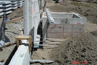
Figure 840.06.H.19 Field Example of the Reinforcing Around an Obstruction
In the detail below, the reinforcing mesh is cut and splayed around the inlet. No angle is required in front of the inlet.
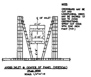
Figure 840.06.H.20 Cutting the Mesh to go around the Obstruction
Coping (840.06.K)
The coping is then placed on the top of the wall. It is used to smooth out the appearance of the top of the wall and to connect adjacent panels at the top of the wall. The wall is completed when the coping is properly installed on top of the wall. The coping has to be cast in place on the top of the wall.
Here is the typical form and reinforcing steel for the coping.
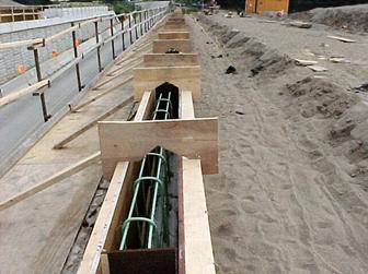
Figure 840.06.K.1 Forming the Coping
Moment Slab
The moment slab is put on the top of the wall to prevent vehicles from going off the roadway. It has to have a large support system to resist these loads. The reinforcing steel is shown below.
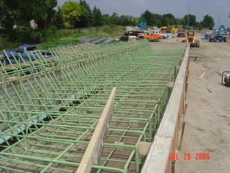
Figure 840.06.K.2 Moment Slab Reinforcing Steel
The finished moment slab is shown below.
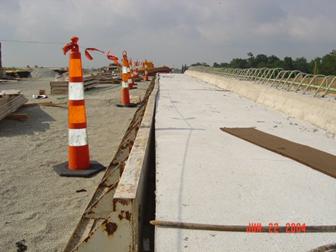
Figure 840.06.K.3 Completed Moment Slab
If your project has a concrete pavement on top of the wall there may be a problem with crack propagation of the barrier joints on to the pavement. Review these details carefully and make adjustments as required.
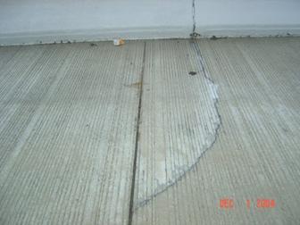
Figure 840.06.K.4 Align the Joints of the Barrier and the Concrete Pavement
Design Conflicts, Design and Construction Loads
Before the actual start of construction of the wall, the various parts of the plans (shop drawings, drainage, lighting, etc.) need to be compared to the contract wall plans to check for conflicts. A conflict may not have been noticed in the design stage. If the plans show heavy loads on the wall and the shop drawings do not indicate it, the Office of Structural Engineering should be contacted. The Designer may have missed loadings from various types of structures. If they did not take these loads into consideration, the wall could bow or even fail. This also can happen for temporary loads that the Contractor may impose such as pile driving.
Final Checks
There are various items that need to be evaluated at the end of the project such as sand leaking out of the joints, open joints, exposed fabric settlement and more.
There are multiple power point presentations on the Office of Constructions web site under Training. The Web site is as following
http://www.dot.state.oh.us/construction/OCA/training/training.htm
Check Lists
The following is a general checklist to follow when constructing a Mechanically Stabilized Earth wall (MSE wall). The answer to each of these should be yes unless the plans, specifications or specific approval has been given otherwise.
YES NO
¨ ¨ 1. Has the contractor submitted wall shop drawings?
¨ ¨ 2. Has the contractor submitted select granular backfill certified test data?
¨ ¨ 3. Has the contractor supplied a the wall suppliers construction manual?
¨ ¨ 4. Have the shop drawings been accepted?
¨ ¨ 5 Do we have the correct panels (shape, size and soil reinforcement connection layout) per the accepted shop drawings?
¨ ¨ 6. Do we have the correct reinforcement (proper length and size)?
¨ ¨ 7. Have the panels and the reinforcement been inspected for damage as outlined in the specifications?
¨ ¨ 8. If any panels or soil reinforcement were found damaged have they been rejected or repaired in accordance with the specifications?
¨ ¨ 9. Are the panels and the soil reinforcement properly stored to prevent damage?
¨ ¨ 10. Has the MSE wall area been excavated to the proper elevation?
¨ ¨ 11. Has the foundation been properly evaluated?
¨ ¨ 12. Has the drainage for the wall been installed ?
¨ ¨ 13. Has the leveling pad area been properly excavated?
¨ ¨ 14. Has the leveling pad been set to the proper vertical and horizontal alignment?
¨ ¨ 15. Has the leveling pad cured for a minimum of 12 hours before any panels are set?
¨ ¨ 16. Is the first row of panels properly placed? Do they have proper spacing, bracing, tilt and where required, do they have the spacers installed?
¨ ¨ 17. Has the proper filter fabric and adhesive been supplied?
¨ ¨ 18. Is the filter fabric being properly placed over the joints?
¨ ¨ 19. Is the adhesive being applied to the fabric then on to the wall?
YES NO
¨ ¨ 20. Is the filter fabric being stored properly (stored out of the sunlight and protected from UV radiation)?
¨ ¨ 21. Is the contractor using the correct panels (correct size, shape and with the proper number of connections) for that panel’s wall location and elevation?
¨ ¨ 22. Is the fill being placed and compacted in 8 inch loose lifts?
¨ ¨ 23. Is the equipment being kept off of the soil reinforcement until a minimum of 8 inches of fill is placed?
¨ ¨ 24. Are the lifts being placed by the proper method and sequence?
¨ ¨ 25. Is the fill being compacted by the correct equipment and in the correct pattern?
¨ ¨ 26. Is the proper compaction being met?
¨ ¨ 27. Is the soil reinforcement being properly connected (connections tight and all of the slack in the soil reinforcement removed)?
¨ ¨ 28. Is the soil reinforcement in the proper alignment?
¨ ¨ 29. Is the vertical and horizontal alignment being checked periodically and adjusted as needed?
¨ ¨ 30. Is the contractor removing the wooden wedges as per the specifications? (The wooden wedges shall be removed as soon as the panel above the wedged panel is completely erected and backfilled.)
¨ ¨ 31. At the end of each day’s operation is the contractor shaping the last layer of backfill to permit runoff of rainwater away from the wall face or providing a positive means of controlling runoff away from the wall such as temporary pipe, etc?
¨ ¨ 32. Has the contractor backfilled the front of the wall?
¨ ¨ 33. Is the coping being installed correctly?
MSE Wall Construction Do’s and Don’ts
1. Review approved shop drawings.
2. Review the Section 840 in the MOP for Mechanically Stabilized Earth (MSE) Walls.
3. Verify leveling pad elevations.
4. Confirm fill material has been tested and approved before it is brought to the job site.
5. Inspect panels.
6. Inspect soil reinforcement for damage.
7. Reject all panels that are not in compliance with the plans and specifications.
8. Ensure panels, soil reinforcement and filter fabrics are properly stored to prevent damage.
9. Ensure the reinforcing can go around all obstructions with less than 15 degrees of splay.
10. Install panels in accordance with the plans and specifications.
11. Place and properly compact fill in accordance with plans and specifications.
12. DO NOT use thick fill lifts. Fill lifts thicker than 8-inch loose lifts require more energy to compact and may move the panels out of alignment.
13. Use corner panels at all corners. If corner panels are not indicated on the plans, the designer should be notified.
14. Soil reinforcement should not be splayed more than 15 degrees from normal. If reinforcement needs to be splayed more than 15 degrees, notify the designer.
15. Check the batter of the panels often. Adjust accordingly. The vertical alignment of the panels below the panels being installed may be affected by the compaction of the soil behind the panels being installed.
16. Check overall batter regularly.
17. When attaching filter fabric to the back of the panels, the adhesive shall be applied to the fabric then attached to the panel.
Out of Tolerances Conditions and Possible Causes Criteria
The following is taken out of FHWA’s Publication “Mechanically Stabilized Earth Walls And Reinforced Soil Slopes Design & Construction Guidelines” NHI Course No. 132042.
Table 16. Out-of-Tolerance Conditions and Possible Causes
MSE structures are to be erected in strict compliance with the structural and aesthetic requirements of the plans, specifications, and contract documents. The desired results can generally be achieved through the use of quality materials, correct construction/erection procedures, and proper inspection. However, there may be occasions when dimensional tolerances and/or aesthetic limits are exceeded. Corrective measures should quickly be taken to bring the work within acceptable limits. Presented below are several out-of-tolerance conditions and their possible causes.
|
Distress |
Possible Causes |
|
1. Distress in wall: Differential settlement or low spot in wall. Overall wall leaning beyond vertical alignment tolerance. Panel contact, resulting in spalling/chipping |
Foundation (subgrade) material too soft or wet for proper bearing. Fill material of poor quality or not properly compacted.
|
|
2. First panel course difficult (impossible) to set and/or maintain level. Panel-to-panel contact resulting in spalling and/or chipping. |
Leveling pad not within tolerance.
|
|
3. Wall out of vertical alignment tolerance (plumbness), or leaning out.
|
Panel not battered sufficiently. Oversized backfill placing and/or compaction equipment working within 3-foot zone of back of wall facing panels. Backfill material placed wet of optimum moisture content. Backfill contains excessive fine materials (beyond the specifications for percent of materials passing a No. 200 sieve). Backfill material pushed against back of facing panel before being compacted above reinforcing elements. Excessive or vibratory compaction of uniform, medium-fine sand (more than 60 percent passing a No. 40 sieve). Backfill material dumped to close to free end of reinforcing elements, then spread toward back of wall, causing displacement of reinforcements and pushing panel out. Shoulder wedges not seated properly. Shoulder clamps not tight. Slack in reinforcement to facing connections. Inconsistent tensioning of the geosynthetic reinforcement. Localized over compaction |
|
4. Wall out of vertical alignment tolerance (plumbness) or leaning in.
|
Excessive batter set in panels for select granular backfill material being used. Inadequate compaction of the backfill. Possible bearing capacity failure. |
|
5. Wall out of horizontal alignment tolerance, or bulging.
|
Backfill material placed wet of optimum moisture content. Backfill contains excessive fine materials (beyond the specifications for percent of materials passing a No. 200 sieve). Backfill material pushed against back of facing panel before being compacted above reinforcing elements. Excessive or vibratory compaction of uniform, medium-fine sand (more than 60 percent passing a No. 40 sieve). Inconsistent tensioning of the geosynthetic reinforcement. Localized over compaction Backfill saturated by heavy rain or improper grading of backfill after each day’s operations. |
|
6. Panels do not fit properly in their intended locations.
|
Panels are not level. Differential settlement (see Cause 1). Panel cast beyond tolerances. Failure to use spacer bar. |
|
7. Large variations in movement of adjacent panels.
|
Backfill material not uniform. Backfill compaction not uniform. Inconsistent setting of facing panels. |
Documentation Requirements – 840 MSE Walls
1. Did the panels arrive with a TE-24?
2. Were the panels rejected or repaired as per the specifications?
3. Was the select granular material approved?
4. If the wall was in a cut were the sidewalls properly protected?
5. Was the foundation properly prepared?
6. Was the drainage properly constructed?
7. Was the filter fabric properly placed?
8. Was the foundation undercut properly constructed?
9. Was the leveling pad placed as specified?
10. Were the wall panels placed according to the plan and markings on the back of the panels?
11. Was external bracing used for the first lift of panels?
12. Were the horizontal and vertical tolerances met?
13. Was the soil reinforcement placed perpendicular to the wall face?
14. Was the SGB placed in 8-inch lifts?
15. Was the backfill compacted to the specification requirements?
16. Was the backfill within 3 feet of the wall compacted to the specification requirements?
17. Did a manufacturer’s representative inspect the site during the wall construction?
18. Did the soils consultant properly take the compaction tests?
19. Was the coping and traffic barrier constructed properly?
20. Were the pile sleeves constructed properly?
21. Perform all the compaction tests according to S-1015 or SS-878.
22. Document on the CA-EW-1,CA-EW-3, CA-EW-8, CA-EW-12 and CA-D-3. Do not duplicate the information on all forms unless necessary