255 Full Depth
Pavement Removal and Rigid Replacement
General
During the life of concrete
pavement, it is sometimes necessary to make repairs to stop progressive
deterioration and to maintain serviceability. Timely repairs restore quality
and provide the rideability and life expectancy for which the pavement was
designed.
Problems may occur at various
stages of the pavement life; it is important that these problems are corrected
as they arise. Corrections are often
necessary during construction, and these repairs must be of the highest
standard in order to achieve the anticipated pavement life. This section establishes a standard repair
procedure and provides uniform application for repairs. These standards are applicable at any time
throughout the pavement life.
Concrete pavement repairs are
classified as full-depth pavement replacement and thin-bonded patching. Full-depth replacement applies when the
damage is more extensive than surface scaling or spalling and requires removal
and replacement for the full depth of the slab.
Thin-bonded patching applies to surface scaling and spalling, spalling
at edges and joints, and other surface deterioration that does not extend below
the pavement mesh. Compliance with all
the provisions of the following standards is necessary to assure durable
repairs and to permanently restore the quality of the pavement.
Description (255.01)
When Standard
Construction Drawing BP-2.5 is called for, rigid replacement applies to the
work. The basic process of full-depth
repairs includes the following:
1. Full-depth diamond blade sawing.
2. Removing the existing pavement full-depth.
3. Removing base material, if specified.
4. Compaction of base material.
5. Drilling dowel bar or tie bar holes.
6. Furnishing and grouting dowel bars and tiebars.
7. Installing mesh when required.
8. Placing, consolidating, finishing, and curing
concrete.
9. Sealing of repaired surface perimeter.
10. Restoring affected shoulders.
Materials (255.02)
Concrete
The concrete to be used must
be 499
Class QC 1, QC FS, or QC MS and will be called out in the pay item description.
Additionally, Rapid Repair Concrete Mix (RRCM) may be called out in the pay
item description. The RRCM mix will require the Contractor to develop and
submit a mix design to the Engineer. The RRCM mix design must develop 400 psi
flexural strength in no less than 4 hours and no more than 6 hours using a 6-inch x 6-inch (150 mm
x 150 mm) beam sample conforming to ASTM C293. The Engineer has
10 days to review and accept or reject the RRCM design.
Curing Materials
The curing material to be
furnished and used must be white-pigmented, liquid membrane forming compounds
meeting 705.07. The shipping containers must be equipped with
mechanical agitators to agitate the material prior to use.
Non-shrink,
Non-metallic Grout
The dowels and tiebars must
be anchored with non-shrink, non-metallic grout material and must set within 30
minutes. Item 705.20
provides the requirements for grout. The
Inspector should check to ensure the proposed grout is on ODOT’s Qualified
Products List.
Reinforcing Steel 709.00
Reinforcing steel for dowel
bars, basket assemblies, deformed bars, tiebars, hook bolts, wiggle bolts, and
couplings must be epoxy coated steel.
Welded Steel Wire
Fabric
Welded steel wire fabric, also
called steel mesh, must comply with Item 709.00.
Dowel Bars and
Basket Assemblies
Dowel bars may be epoxy
coated steel 709.13
or Fiber Reinforced Polymer (FRP) bars 705.01. Basket assemblies must be epoxy coated steel.
Removal of
Existing Pavement (255.03)
The Engineer must mark the
limits of the areas to be repaired. The
minimum longitudinal length of a repair is 6 feet (1.8 meters). All pavement repairs must be the full lane width,
unless otherwise detailed by the plans.
The existing pavement is
sawed full-depth at the limits established by the Engineer with a diamond saw
blade. Normally, the existing concrete
pavement thickness is given in the plans; however, there may be projects where
the existing pavement was built thicker than shown in the repair plan.
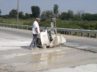
Figure
255.A – Full-Depth Diamond Blade Saws
Concrete sawing and removal
depths may be as much as 1 inch (25 mm) greater than indicated on the repair
plan without additional compensation to the Contractor.
If there is an existing
asphalt overlay on the concrete pavement, the Contractor may elect to saw
full-depth through the asphalt concrete and the Portland cement concrete. Depending on the thickness of each material,
the Contractor may not be capable of sawing through both courses and may make
an offset saw cut through the asphalt course, remove enough asphalt to allow
room for a diamond saw, then make a full-depth saw cut through the concrete
pavement. If the Contractor elects to
make offset cuts to facilitate removal, the offset cut will not be measured for
payment. Only full-depth saw cuts that are made at the limits of the removal
are measured for payment. Any
intermediate saw cuts made by the Contractor to facilitate removal by the lift
out method are not measured for payment.
During hot weather, it may be
necessary for the Contractor to saw only at night or in the morning when cooler
temperatures prevail. Concrete pavement
heats up and expands as temperatures rise during hot summer days. Diamond saw blades could be pinched and lock
up when sawing due to slab expansion.
Some contractors use a carbide-tipped saw to cut through the pavement within
the repair area. This is permitted
provided that the Contractor does not damage the base under the pavement to be
removed. All perimeter saw cuts must be
made with diamond saws.
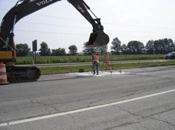
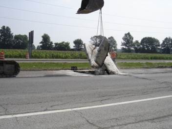
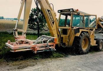
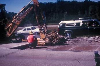
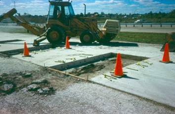
Figure
255.B – Pavement Removal by the Lift-out Method
Removal of the concrete
follows the full-depth sawing operation.
The lift-out method is required in order to not disturb the base
material under the pavement and to minimize damage to the adjacent pavement
that is to remain. Holes are drilled
within the removal area and lift pins are inserted. The slab, or portion of the slab, is then
removed by lifting the slab vertically with a crane or large backhoe. After lifting, loose debris left behind is removed
by hand. The removed pavement is
disposed of in accordance with Item 202.02.
The use of a pavement breaker
and backhoe for removal is not permitted unless the Engineer determines that
the lift-out method is not practical due to extensively deteriorated pavement,
the existence of asphalt concrete full-depth repairs, or old concrete pavement
repairs, which are extensively cracked and deteriorated. There will be no additional compensation for
removal of the existing pavement with a pavement breaker and backhoe.
Regardless of the method used
to remove the pavement, if the face of the pavement to remain is damaged by
sawing or removal operations, an additional full-depth saw cut is required for
the full width of the lane or lanes at a distance from the first cut, which
includes the damaged pavement. The
additional pavement repair area and the additional saw cut is not measured for
payment.
After pavement is removed
from the area to be repaired, an additional saw cut must be made if the face of
the remaining pavement or shoulder is deteriorated on the bottom to a height
greater than 1/4 of the pavement thickness.
The additional saw cut should encompass the deteriorated areas. The additional saw cut and repair area is
measured for payment.
Removed pavement shall be
disposed of in accordance with 202.02. The Inspector shall determine and document
where and how pavement is being disposed by the Contractor.
Correction of
Subgrade (255.04)
Prior to placing the concrete
in the removal area, and before installing dowels or tiebars, shape and compact
the base or subgrade material. Any area
that has been over-excavated must be filled with concrete.
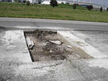
Figure
255.C – Debris Remaining after Removal by the Lift-Out Method is Removed by
Hand Methods
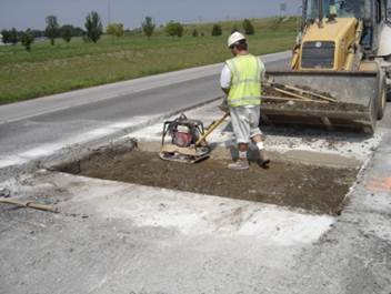
Figure
255.D – Compaction of Base
If undercut joints at the
limits of the repair areas are specified, the Contractor must be careful when
removing the base material to create the undercut section. The undercut section is the void created by
removing the base material from underneath the existing, remaining
pavement. This undercut will be filled
with concrete when placing the new pavement repair. Refer to Standard
Construction Drawing BP-2.5 for undercut joint details. Damage to the bottom of the slab that is to
remain cannot be tolerated. Any damage
caused by the Contractor’s operations requires additional removal and
replacement at no additional cost. If a
backhoe bucket plate is used, exercise care, or use hand methods to excavate
under the existing slab. Undercut work
is incidental and included in the pay item.
Placing Dowels
and Tiebars (255.05)
Dowels could be smooth or
deformed steel bars depending on the type of joint (transverse contraction or
transverse tied). Smooth dowels are
1-1/2 inch (38 mm) in diameter by 14 inches (355 mm) in length. Fiber-reinforced polymer dowel bars may be used
in lieu of smooth steel dowels. Deformed
bars are No. 11 (No. 35M) by 14 inches (355 mm) in length. Refer to Standard
Construction Drawing BP-2.5 for details on tied and contraction joint requirements.
Holes for dowels and tie bars
are drilled in the existing concrete slab by using hydraulic or electric
drills. Drilling is to be done in a
manner that will not spall or damage the existing concrete. Pneumatic drills are not to be used. Holes must be drilled with a device that
allows independent adjustment of all drill shafts in the horizontal and
vertical direction. The device must be
capable of drilling a minimum of three holes at one time.
Holes for dowel and tie bars
are to be centered at mid-slab within a tolerance of ±1/2 inch (13 mm). Dowels are spaced starting 12 inches (300 mm)
from the outside edge of pavement, are spaced at 12 inches (305 mm), and stop
24 inches (600 mm) from the adjacent lane to avoid hitting existing tiebars at the
longitudinal joint. This will result in
10 bars in each 12 foot lane. The
Contractor must drill dowel holes parallel to the pavement surface and the
centerline, otherwise the smooth dowels will not perform properly when the
pavement expands and contracts.
Figure
255.E – Hole Drilling Equipment
Holes for dowels or tiebars
must be 1-5/8 inches (41 mm) in diameter and a minimum of 7 inches (178 mm)
deep into the concrete.
Longitudinal
Joints
Full-depth repairs that are
greater than 10 feet (3.0 meters) in length will require a tied longitudinal
joint using No. 5 x 24-inch (No. 16M x 600) tiebars or hook bolts spaced at no
more than 30 inches (760 mm) and not less than 24 inches (610 mm). Refer to Standard
Construction Drawings BP-2.1 and BP-2.5 for more details. Holes for longitudinal tiebars must be 3/4
inches (19 mm) in diameter and a minimum of 12 inches (300 mm) deep into the
concrete.
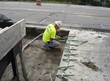
Grouting
Dowels or Tiebars
This section details the
requirements for transverse dowels and tiebars.
The requirements for tied longitudinal joints are the same; however, the
bar dimensions differ. All dowels and
tiebars must be grouted into place with a non-shrink, non-metallic grout
material. Prior to injecting grout, the
holes must be blown clean with oil-free compressed air. The hole must be dry and frost free before
grouting dowels or tiebars.
The grout must be injected
pneumatically into the back of the hole and the dowel or tiebar inserted 7
inches (178 mm) into the hole. A nylon
or plastic washer (called a grout retention disc) is then pushed flush against
the saw cut after the bar is installed to keep the grout in the hole. Grout retention discs must be clear or opaque
white in color. Sufficient grout must be
used to completely fill all voids around the bar, including any spalling at the
face of the saw cut. Grout should
extrude through the slot in the grout retention disc after filling and
inserting the dowel or tiebar. Other
methods of installing dowels or tiebars are not permitted.
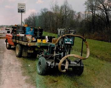
Figure
255.F – Typical Grout Injection Equipment
Most contractors pump the
resin and hardener from separate pressure pots. The two materials are mixed immediately
before being injected into the hole through a baffled mixing tube. In cooler temperatures, it may be necessary
to heat the grout materials to promote flow and to allow set up in the required
30 minute time period. Dowels or tiebars
must be held in proper alignment until the grout has hardened.
Figure
255.H – Insert Steel Rods with Grout Discs in Place
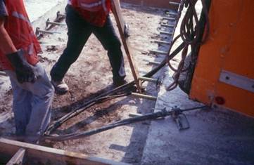
Figure
255.I – Using a Spud Bar to Push Steel Rod into Place
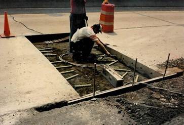
Placement of
Portland Cement Concrete (255.06)
Placement of the concrete can
begin when the grout around dowels or tiebars has hardened. Smooth dowels must be coated with new, light
form oil before concrete is placed.
Rigid forms are required at the outside edge of the full-depth
repair. The concrete must be placed in a
continuous operation and consolidated with internal vibration.
Figure
255.J – Rigid Forms Installed at Shoulders
Full-depth repairs that are greater
than 10 feet (3.0 meters) in length, or will be opened to traffic within 24
hours of placement, require W8.5 or D8.5 wire fabric reinforcement. The clearance from the end of the wire fabric
to the edge of the pavement or new transverse joint is 4 ± 2 inches (100 mm ±
50 mm). Refer to Standard
Construction Drawing BP-2.5 for details.
When using RRCM concrete the
Contractor is required to install maturity sensors to measure the maturity of
each day’s placement. At least two sensors should be installed for each work
day. Install the first sensor where maturity gain is expected to be the
slowest. Maturity gain is typically slowest in the thinnest section of pavement
or volumetrically smallest patch or repair. If all sections, patches, or
repairs have the same dimensions and no concrete is expected to gain maturity
slower than another, install the first sensor randomly in concrete from any
load, except the last load. Install the other sensor in concrete from the last
load mixed and placed that day. See Supplement
1098 for additional details on maturity curve development and use during
construction.
Figure
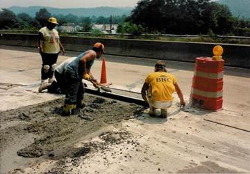
255.K – Screeding of Repair Area
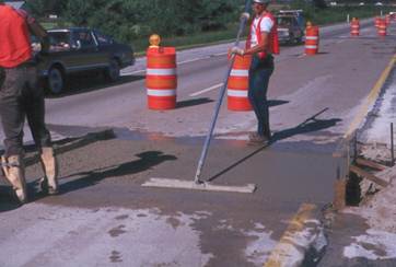
Figure
255.L – Bull Floating the Repair Area
Specifications require that
repairs less than 12 feet (3.7 meters) in length be screeded parallel with the
centerline. If the repair is 12 feet
(3.7 meters) or longer in length, the screed must be perpendicular to the
centerline. After screeding and floating
is complete, the surface must be tested with a 10 foot (3.0 meter) straightedge
before the concrete hardens to ensure that the transition on and off the repair
meets a tolerance of 1/8 inch in 10 feet (3 mm in 3.0 m). Any high or low areas must be corrected and
the surface rechecked to assure compliance.
The surface finish of the
concrete repair must match the adjacent concrete. If the adjacent pavement is smoothed with a
burlap drag, the patch should have the same finish. If the patch texture is different, it may be
very noticeable when traveling over the patch at normal traffic speed.
After finishing and
straightedge checking is complete, the concrete must be cured with white pigmented
curing membrane as per 705.07,
Type 2. A uniform coverage of membrane
is required at an application rate of 150 square feet per gallon (1 liter per
3.7 square meters).
Wearing Course
Replacement (255.07)
If asphalt was removed from
the top of the existing pavement, it must be replaced with either 301
or 448
Type II material as shown in the plans.
Compact these mixtures as approved by the Engineer using any of the
roller types specified in 401.13. Prior to placing the hot mix asphalt
concrete, apply a tack coat on the repaired surface per 407.
Vertically trim all
transverse joints to a 1-1/2 inch (38 mm) minimum before placing the final
asphalt concrete layer adjacent to the existing pavement.
Seal the perimeter surface of
repaired areas 4 inches (100 mm) wide by applying approved 702.04
asphalt material, RS-1, RS-2, CRS-1, CRS-2, or 702.01
approved PG binder.
Shoulders must be restored to
the original line and grade with aggregate or asphalt concrete as directed by
the Engineer or as shown in the plans.
Fill low areas and compact them flush with the surrounding shoulder.
Opening to
Traffic (255.08)
Full-depth repairs can be
opened to traffic when the concrete attains a modulus of rupture of 400 psi
(2.8 Mpa). For RCCM mixes, do not open
the rigid replacement to traffic until the RCCM attains a modulus of rupture of
400 pounds per square inch (2.8 MPa) based on maturity testing. The time to
obtain this strength will vary depending on the class of concrete used and the
atmospheric conditions.
When traffic is maintained
adjacent to the lane being repaired, the Contractor must schedule his work so
that slab replacements are completed within 48 hours after removing the
existing pavement. At the end of a daily
work shift, unfilled repairs, 10 feet (3.0 meters) and less in length must be
covered with steel plates.
The Contractor must plan work
so that no repairs are left unfilled when work is suspended for holidays or
weekends. If the Contractor has removed
pavement and is unable to complete the repairs in the above time, he must fill
the areas with a suitable, temporary patch material to the satisfaction of the
Engineer. These areas must be maintained
by the Contractor.
Method of
Measurement (255.09)
The Department will measure
the quantity of full-depth pavement removal and rigid replacement by the number
of square yards (square meters) repaired in the completed and accepted work.
Full-depth pavement sawing is
measured by the number of feet (meters) of perimeter full-depth saw cuts made
in the completed and accepted work. The
Department will not measure any offset cuts, pressure relief cuts, or other saw
cuts made to facilitate pavement removal.
Basis of Payment
(255.10)
Payment is full compensation
for all work specified in this item.
Payment for accepted quantities of the full-depth pavement removal and
rigid replacement item is at the contract price per square yard (square meter).
Payment for the full-depth
pavement sawing item is at the Contract price per linear foot (meter). The
Department will not pay for additional concrete sawing and removal depths
within 1 inch (25 mm) greater than those shown on the plans.
The Department will not pay
for additional work to repair damage caused by pavement sawing or pavement
removal.
The Department will include
tack coat in the cost of the asphalt concrete. The Department will pay for
asphalt concrete according to Item 301 or Item 448.
Documentation
Requirements - 255 Full Depth Pavement Removal and Rigid Replacement
1. Locate, mark, and record areas to be replaced.
2. Document removal of existing pavement and note if
damage occurred due to removal operation.
3. Document the disposal of waste material.
4. Measure and record saw cuts. Full-depth saw cuts are an additional pay
item paid by the linear foot.
5. Document any damage to existing base material or subgrade
during pavement removal operation.
6. Document preparation and compaction of base material
or subgrade.
7. Document type of equipment used for drilling holes for
dowel bars; depth of holes; holes blown clean before dowel bars placed.
8. Document dowel and tiebar sizes, spacing, and
alignment; approved grout, method of grout placement, and use of grout
retention discs.
9. Document placement of concrete in accordance with 451.06
and direction of screeding.
10. Document surface tolerance checks with straightedge
and any corrections made.
11. Calculate and document curing compound used and
required.
12. Document times and results of beam breaks or maturity
readings.
13. Measure and pay as per 255.10.
14. Show documentation on CA-D-6
or other approved form.