422 Chip Seal
Description
(422.01)
Chip seal consists of the application
of polymer modified asphalt emulsion covered by an aggregate course. It is applied as a single or double chip seal
for use as a surface course on all types of pavements and on paved berms. Chip seal can also be used as an intermediate
course for a hot mix asphalt surface course.
The purpose of a chip seal is
to seal and protect the underlying course from weathering and from wear by
traffic. A coating of asphalt material
helps seal existing pavement cracks and joints; the cover aggregate provides a
skid-resistant surface.
When applied on berms, the
cover aggregate provides delineation of the traffic lanes from the berms by a
change in surface color and texture.
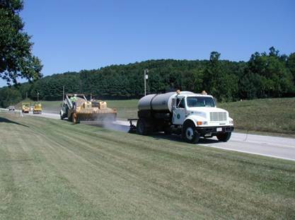
Figure 422.A – Chip Seal
Operation
Materials
(422.02)
Chip seals require the use of
either an emulsified binder or a polymer emulsified binder depending on the
Average Daily Traffic (ADT) counts. Only
asphalt binder materials meeting the requirements of 422.07
are permitted. Asphalt binder is shipped
under ODOTs Asphalt Materials Certification
Requirements as detailed in Supplement
1032. Ensure that the material used
on the project is from a certified source.
Cover aggregate must be
washed limestone or dolomite meeting 703.05. Aggregates with a source designated as “SR”
cannot be used. The Laboratory maintains
The Aggregate Source Group list that designates aggregate sources that do not
provide acceptable friction characteristics and may become polished or slippery
with wear. These aggregates are
designated as “SR” or “SRH.”
Cover aggregate for chip
seals must be sampled and approved prior to use. Sampling occurs at the source stockpile and
at a staging stockpile location. For example, at the job
site. If there is doubt as to
whether any stockpile continues to meet the required aggregate gradations, the
District can sample and test at any time.
The Contractor must submit a
mix design for the chip seal and receive a Job Mix Formula (JMF)
from the Laboratory.
Equipment
(422.03)
Distributors
The Inspector must make a
general examination of the distributor to ensure compliance with the
requirements of this specification and 407.03. The equipment used for the application of a
tack coat is the same as used for the application of the polymer binder for
chip seal, but must include a computerized rate control that automatically
adjusts the binder pump to the unit ground speed. This control must have a gauge or meter (in
gallons) that is easily read. The spray
nozzles must be appropriate for the material and rate specified. In addition, the approval of the distributor
is based on observation of the operation and check measurements of the actual
application rate, performed as described in the following paragraphs. The
Inspector should have the Contractor demonstrate the use of the required volume
measuring device, thermometer, and application controls. Work should not be permitted to start if this
equipment is unsatisfactory.
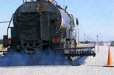
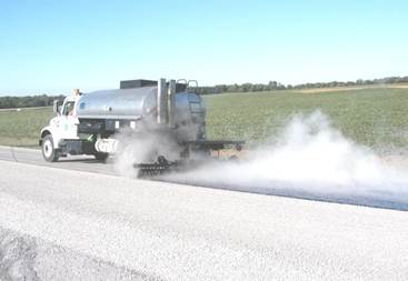
Figure 422.B – Distributor
Trucks Applying Binder
The operation of the
distributor is judged by visual observation.
The quantity of material flowing from each nozzle should appear
uniform. The angle of each
"fan" of material with the spray bar should appear to be the same;
the angle is specified by the manufacturer.
The material should be applied uniformly across the width of the
pavement, with no visible streaks and with no apparent variations in thickness,
from the beginning to the end of the run.
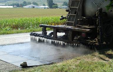
Figure 422.C – Distributor
with Improperly Aligned Nozzles (at different angles)
Streaking or ridging will not
be tolerated when applying polymer binder for chip seal work. This type of defect is generally caused by
nozzles that are not all at the same angle in respect to the spray bar. The Inspector must approve or prohibit use of
a particular distributor accordingly.
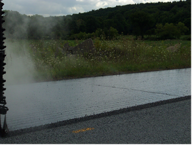
Figure 422.D – Unacceptable
Application of “Ridged” Binder
The results of the foregoing
observations and the results of the test section are recorded for each
distributor proposed for use, together with a means of identification (license
plate or equipment number), and indication of approval or non-approval. This information is entered in the project
record as a supplement to the Inspector's
Daily Report.
After the initial inspection,
continued approved status of a given distributor depends on continued
satisfactory results determined visually or by additional checks when deemed
advisable.
Rollers
Only Type II pneumatic
rollers conforming to 401.13
are permitted for embedding the cover aggregate; however, the maximum capacity
shall not apply.
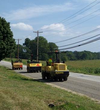
Figure 422.E – Type II
Pneumatic Tire Rollers
Aggregate Spreaders
The aggregate spreader must
be self-propelled with a variable width aggregate hopper (8 to 16 feet) and
shall conform to specification 422.03. The spreader must produce a uniform
application of aggregate without gaps or ridges at the rate specified. Spreaders must have pneumatic tires, a screen
to prevent oversized material from passing through to the roadway, revolving
cylinders, and adjustments.
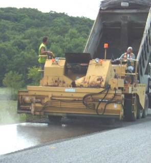
Figure 422.F – Aggregate
Spreader
Brooms
Rotary brooms are used for
the initial surface preparation to sweep the roadway prior to the application
of the polymer binder. After the cover
aggregate application, a rotary broom or sweeper is required to sweep excess
aggregate from the completed surface without dislodging the embedded
aggregate. Be sure that aggregate is not
being swept onto adjacent lawns.
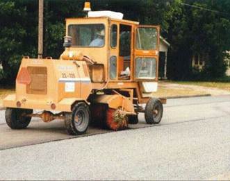
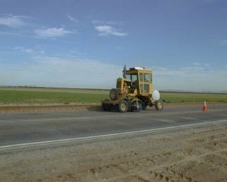
Figure 422.G – Rotary
Brooms
Weather
Limitations (422.04)
For chip seals, the weather
limitations are specified in 422.04. This section requires a minimum pavement and
air temperature of 60 °F (16 ºC). Work
should not begin if temperatures are forecasted to be below 50 °F (10 ºC)
within 24 hours from the start of work.
Do not place the chip seal if the existing pavement temperature is 140
°F (60 °C) or above. This work is not to
be done before May 1 or after September 1.
These requirements are meant to produce quality chip seals; cool
temperatures and cloudy days make application of chip seal more difficult, as
is takes longer for the binder to cure out than in the heat of summer.
Test
Strip (422.05)
The Contractor is required to
provide a test strip to demonstrate that the equipment and operations can meet
the requirements of the specifications.
The test strip must be 1000
feet long by 1 lane width wide. The test
strip must be continuous. The test strip is used to determine the binder
application rate, the aggregate application rate, and the aggregate
gradation.
During the test strip, the
aggregate spreader will be calibrated by applying aggregate to a piece of
cardboard of a known size (generally 1 square yard). The material is collected from the cardboard
and weighed to determine the application rate (pounds/square yard). Based on acceptance of the test strip, this
will be the rate of cover aggregate application.
The proper binder application
rate will be determined. Initially the
binder should be applied at the target rate specified. The depth of embedment of the aggregate will
be checked visually. A good rate of
application will provide an average of 2/3 embedment of the chip in the binder
after rolling. The Engineer will require
adjustments to the rate as needed to obtain the proper embedment. The rate will be calculated using the test
strip dimensions and the number of gallons used as measured by the distributor
gauge or meter (gallons/square yard).
The Engineer will review the
test strip the following day. The
acceptance criteria of 422.11
will be used to determine acceptance of the test strip. These criteria include proper chip embedment,
binder streaking, ridging, flushing, loss of cover aggregate,
and joint construction. The Engineer may
require another test strip if there are problems with the application.
The test strip cannot be waived and is required on
every project.
Surface
Preparation (422.06)
Before a chip seal is applied
to an existing surface, all material accumulations, debris, foreign objects,
dust, leaves, soil, etc. that would interfere with the adhesion of the asphalt
material must be removed. Proper
cleaning of the surface requires power brooming and
may necessitate hand scraping and power blading of heavy accumulations, such as
mud. Hand brooming
may be necessary. Special attention
should be given to the edges of the roadway to ensure proper coverage of the
width intended.
All existing polyester,
thermoplastic, and epoxy pavement markings must be removed using an abrasion
method prior to placement of the chip seal.
Acceptable removal methods include sand, shot, or water blast. Grinding is not allowed.
For single chip seals, raised
pavement markers (RPMs) must be removed or
covered/protected during the chip seal operation. Any removed RPMs
must be replaced unless otherwise shown on the plans.
For double chip seals RPMs must be removed.
Removed RPMs must be replaced unless otherwise
shown on the plans.
Binder
Application (422.07)
A uniform application in the
transverse and in the longitudinal direction is important. Continued application should not be permitted
when visible defects occur. Where
distributor results are erratic, discontinue use of the equipment until the
problem is corrected.
The binder must be maintained
at 150 °F to 185 °F (65 °C to 85 °C) during application and at the beginning of
the day. Binder is not to be reheated at
a rate faster than 25 °F (14 °C) per hour when it has been allowed to cool to
below 150 °F (65 °C).
With all other conditions
being equal, the application rate of asphalt material depends on the average
size of the cover aggregate particles.
In a good chip seal, the average size aggregate will be embedded for
approximately 2/3 of its height after thorough seating by rolling. This can be checked by pulling out chips by
hand and visually inspecting how much of the chip is coated. When the binder application rate is too
heavy, the particles may become totally embedded, resulting in a flushed or
bleeding surface. When the application
rate is too light, the particles may not be held with sufficient firmness to
resist dislodging by traffic, and a loss of cover aggregate will result.
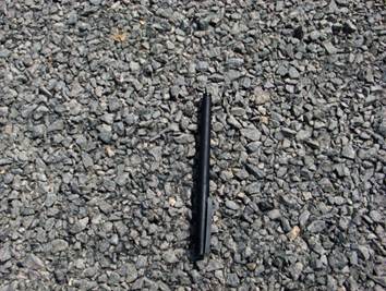
Figure 422.H – Aggregate
Embedment after Rolling
The binder application rate
required to produce proper embedment for a given particle size may depend upon
the porosity, absorption, and firmness of the surface to be sealed. The target rate determined by the test strip
may need field adjustment depending upon the actual nature of the surface. Considerable judgment is required to
determine the proper application rate and to avoid undesirable effects of
bleeding or raveling. If proper stone
embedment is not obtained, the Engineer must be notified, and the application
rate adjusted and documented.
The binder application must
be started and stopped on a removable protective cover of paper, cardboard,
metal or other material that protects the adjacent pavement or previous chip
seal from being coated. The use of the
protective cover allows the binder to be applied at the full rate at each
ending and beginning point, but does not allow the binder to be applied to
existing pavement, or over applied on a previously constructed chip seal. The binder application must not be lapped,
such as where one day’s production meets the next. The protective cover must be removed
immediately after use.
Cover
Aggregate Application (422.08)
Only aggregate that has been
approved is permitted for use. Collect
the weight tickets when the material is received at the paving site.
The previously established
spreading rate of aggregate must be verified using a 1 square yard of
cardboard, weighing and determining pounds per square yard. The Contractor must make adjustments to the
spreader to meet the test section calibrated rate.
The aggregate must be
sufficiently free from dust and moisture to permit immediate adhesion of the
asphalt material. Material delivered to
the site with water running from the bed of the truck must be rejected.
Excessive application of
cover aggregate and amounts of aggregates considered to be a nuisance to the
public will require the work to be stopped.
It is unacceptable to rely on brooming or
vacuuming to remove excess aggregate.
The spreading operation requires recalibration in these cases.
Construction
Operation (422.09)
General
Considerations
The Contractor must establish
stations for the project at 1,000 foot intervals before placing any
material. The stationing must be clearly
marked and be maintained throughout the project. Stationing is typically provided using wooden
lath along the roadway and the markings should be easy to read.
The binder distributor,
aggregate spreader, and rollers must be as close to each other as
possible. The binder distributor cannot
be more than 150 feet ahead of the aggregate spreader.
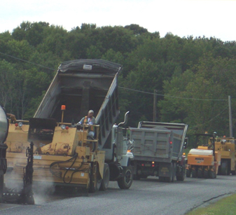
Figure 422.I – Keep the
Distributor, Spreader, and Rollers Close Together
The longitudinal joint must
be placed on a lane line or as the Engineer directs. For double chip seals, the longitudinal joint
for the first course is to be placed 6 inches off the centerline, and the
second course is to be placed on the centerline.
Where a double chip seal is
required by the plans, the first course must be cured, swept, and capable of
withstanding construction traffic. Any
deficiencies or damage must be corrected before placing the second course of
chip seal.
Rolling
Rolling of the chip seal
cover aggregate is required to begin immediately behind the aggregate
spreader. Three rollers minimum are
required. Do not allow the aggregate to
go unrolled for more than 5 minutes.
This is to ensure that the aggregate particles will be embedded in the
asphalt binder before the binder sets up.
If the binder sets before the aggregate is rolled, the result will be
loose stone that must be removed. That
section of roadway would be unacceptable and would require rework.
The specifications require a
minimum of two complete roller passes of the cover aggregate. A single complete pass is forward and back
over the same area. Each new pass must
be overlapped by one-half of the roller width.
While making these passes, the speed of the roller must be slow enough,
not greater than 5 miles per hour (8 km/h), to avoid displacing or dislodging
the aggregate particles from the asphalt.
If stone is being picked up by the rollers, have the Contractor adjust
the speed.
Sweeping and Opening
to Traffic
Sweep the chip seal within 4
hours of placement of the cover aggregate using a power broom to remove loose
aggregate. The Contractor cannot reuse
this aggregate in the double chip seal course.
There may be issues that do not allow the Contractor to sweep within the
4 hour timeframe, such as stone moisture, high humidity, slow binder cure rate,
rain, etc. In this case, the Engineer
may suspend the operation until the problem is resolved or more favorable
conditions prevail which allow for sweeping within 4 hours.
Make sure sweeping extends 1
foot beyond the edge of the roadway to remove any loose aggregate that could
migrate back to the roadway.
Before opening the road to
traffic, the contractor must place “Loose Stone” and “35 MPH” signs on the same
post spaced at 0.5 mile intervals. Signs
must conform to Item 614.
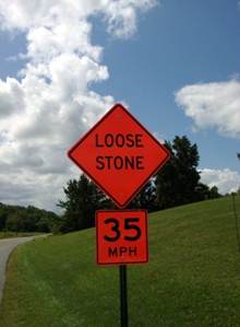
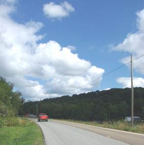
Figure 422.J – “Loose
Stone” Sign and Pilot Vehicle
On two-lane roads where
traffic is being maintained on a chip seal, the Contractor must provide a pilot
vehicle at 25 mph to guide traffic through the work zone.
The Contractor is responsible
for all damage claims that result from his operations, and the chip seal
surface, until the application of the final pavement markings or the
application of a fog seal if required.
Quality
Control (422.10)
The Contractor is required to
provide quality control of the chip seal process and must stop placement and
notify the Engineer and DET if any of the parameter
tolerances are exceeded. The Contractor
must identify and correct problems and receive permission from the Engineer to
restart the chip seal operation.
Additionally, the Department can obtain samples at any time. Aggregate samples can be taken from the
stockpile or from the spreader to test for conformance. If Department testing shows out of compliance
material, work can be stopped.
The Contractor is to provide
an asphalt binder sample on a daily basis for the Department. The sample is to be collected within 1 hour
of the start of production from the distributor truck. The sample must be collected in a plastic
container with a plastic screw lid.
After sample collection, the Contractor must give the sample to the
Engineer the same day it is collected.
Additional samples may be requested by the Engineer at any time.
The binder application rate
cannot exceed ±0.02 gallons per square yard from the established application
rate.
Aggregate must meet a
specific moisture content and gradation as provided in 422.10. The Contractor is required to reject material
that does not meet these requirements.
If water is seen running from the truck bed when aggregate is brought to
the job, it must be rejected.
The Contractor must provide a
daily quality control report to the Engineer that includes the specific
information as listed in 422.10.
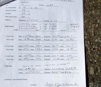
Figure 422.K – Example of
Daily Quality Control (page 1) Report by the Contractor
These items should be on the
Contractor’s daily quality control report.
·
Control section,
project number, county, route, and Engineer.
·
Date, air and
pavement temperature, and humidity.
·
Binder
temperature.
·
Beginning and
ending stations.
·
Yield check on
binder and aggregate (3 times per day).
·
Gradation,
moisture content, and identifying station of aggregate samples.
·
Length, width,
and total area chip sealed.
·
Condition of
signs.
·
Contractor’s
signature.
Acceptance
(422.11)
Acceptance of the final
product depends on daily inspection of the six items listed in 422.11
and final inspection after 25 to 35 days for the defects listed in 422.11.
Daily Inspection and
Acceptance
- The finished surface shall have no more than four tears or
untreated areas greater than 1 inch wide and 4 inches long in any 120
square yard area.
- Joints are neat and uniform; there is no buildup, uncovered areas,
or other unsightly appearance.
- Longitudinal joints have less than a 2-inch overlap.
- Transverse joints have no more than 1/4 inch difference in
elevation as measured across the joint using a 6-foot straightedge.
- The edge of the chip seal does not vary more than 2 inches in any
100 feet along a shoulder or edge.
- Typical stone embedment is two-thirds of a typical chip.
Final Project
Acceptance
Deficiencies in chip seal
construction often do not show up until the surface has been under traffic for
a period of time. The Engineer and
Contractor will review the completed chip seal in 25 to 35 days after
placement. Surface patterns that show
streaking or ridging; bleeding/flushing; and loss of cover aggregate are to be
specifically evaluated. The Contractor
is required to perform corrective work when any one defect exceeds 20 percent
of any 120 square yard area. The following
are descriptions of these defects and likely causes.
Surface Patterns (Ridges
and Streaking)
Streaking is caused by faulty
distributor adjustment or operation, which result in the asphalt being placed
in ridges. Contrary to popular belief,
these ridges will not "flow" together, particularly when the cover
aggregate is applied immediately after the application of asphalt material as
required by the specifications.
Streaking results in insufficient asphalt material between the ridges to
hold the aggregate in place. This
aggregate is loose and will be “kicked up” by traffic. This leaves only the aggregate that was
embedded in the ridged asphalt, thus producing a streaked appearance.
Figure 422.L – Streaking
and Ridging in Completed Chip Seal
Bleeding/Flushing
Bleeding and flushing is
defined as a migration of asphalt material to the surface, completely or almost
completely submerging the cover aggregate.
Continuous bleeding is likely the result of too high a rate of application. Spotty bleeding usually is the result of
variations in the surface of the existing pavement. Bleeding at tie-ins between distributor loads
is the result of an overlap of the previous run.
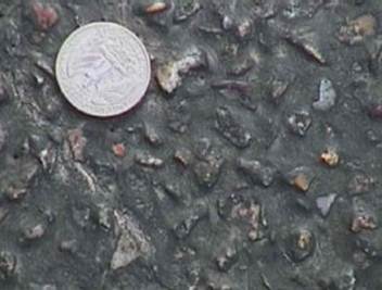
Figure 422.M – “Bleeding”
or “Flushing” of a Chip Seal
Loss of Cover
Aggregate
Loss of cover aggregate is
the detachment, loosening, or stripping away of the aggregate material from the
asphalt binder leaving behind a black shiny surface. This is a serious form of chip seal failure
because of the traffic hazard created by the exposure to the slippery film of
uncoated asphalt binder material and loose aggregate particles. It may be caused by one or more of the
following:
- Too light an application of the asphalt material.
- Penetration of the asphalt material into the
underlying surface.
- Use of an improper grade of asphalt material for
existing conditions.
- Delay in spreading the aggregate on the asphalt
emulsion (binder has set-up).
- Excess aggregate application.
- Lack of adequate rolling.
- Use of wet or dirty aggregate.
- Opening the roadway to traffic before adequate
curing has taken place.
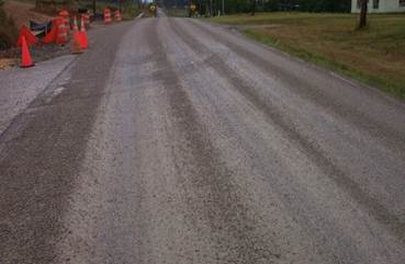
Figure 422.N – Loss of
Cover Aggregate
Method
of Measurement (422.12) and Basis of
Payment (422.13)
Single or double chip seals
are measured by the number of square yards in place and accepted. The actual width and length along the
centerline of chip is measured for pay.
The cost of the removal of
all pavement markings required according to 422.06
is incidental to the chip seal item.
Payment includes any costs to
make repairs to deficient chip seals.
Where RPMs
are removed for a double chip seal, the department will pay for the removal
under Item 621
Raised
Pavement Markers Removed. However, the removal of RPMs for a single chip seal
is included for pay with the chip seal
item.
For single chip seals, the
cost of replacing of RPMs that are removed by the
Contractor is included in the Chip Seal item unless the plans specifically
state that they are not to be replaced.
For double chip seals, the
cost of replacing RPMs should be set-up as a separate
item unless the plans specifically state that they are not to be replaced.
Documentation
Requirements - 422 Chip Seal with Polymer Binder
1. Inspect and document all equipment suitability based
on the specification requirements (distributor, aggregate spreader, rollers).
2. The results of the test section must be documented,
including calibration of the aggregate spreader, adjustments to binder
application rate, and the Engineer’s review comments.
3. Bills of lading for the binder and aggregate must be
included in the project records.
4. During chip seal placement, document air and pavement
temperatures; binder and aggregate application operations; rolling procedure; brooming; and traffic control procedures, including all
signing and use of pilot car.
5. The Contractor must provide a Quality Control report
with the information listed in section 422.10
of the specifications.
6. Inspect and document the completed chip seal for
initial and daily acceptance.
7. Inspect and document the completed chip seal for final
acceptance within 25 to 35 days after placement.
8. Measure and calculate for payment accepted chip seal using
the actual width of placement and the length along the centerline of the
roadway. Payment is in square yards.