511 Concrete for
Structures
Materials (511.02)
Item 511.02
requires all concrete above the ground line in a given substructure unit or all
concrete for any given superstructure be made of aggregate of the same kind and
color, except upon permission of the Engineer.
Concrete
(511.03)
Concrete for structures will
be Class QC 1, QC 2, QC 3, or QC 4, or as specified in the Contract documents.
The mix design and control are outlined in Item 499
and in Supplement
1126, except when modified as specified.
The Contractor has to submit,
in writing, the Department accepted Job Mix Formula (JMF)
to the Engineer, for a check for conformance to contract requirements, at least
ten days before placing concrete.
Quality
Control Requirements and Mass Concrete (511.04)
When the contract requires
Quality Control/Quality Assurance, (QC/QA) Concrete, in addition to the JMF, the Contractor is required to submit a Quality Control
Plan (QCP) for the work and perform quality control
testing of the concrete as specified in C&MS 455.
Also per C&MS 455,
the Department or its representative will perform Quality Assurance sampling
and testing as specified or as deemed necessary.
For quality assurance, the Engineer will make
acceptance test cylinders as follows:
1. Structure over 20 foot span. A set of test cylinders
from each 200 cubic yards of concrete or fraction thereof incorporated into the
work each day.
2. Structures of 20 foot span or less. At least one set
of test cylinders for each 50 cubic yards of concrete.
The Contractor must provide a
sealed, temperature controlled, Concrete Cylinder Curing Box (CCCB) capable of holding at least twelve 4-inch
x 8-inch cylinders for both quality control and quality assurance cylinders.
Mass Concrete
Requirements (511.04.A)
Mass Concrete is defined as
concrete components with a minimum dimension of 5 feet. In C&MS 499,
QC-4 is the designated class of concrete for Mass Concrete mix designs. In
addition to submitting a mix design, per
C&MS 499.03
and Supplement
1126, a Quality Control Plan per C&MS 455,
the Contractor is also required to submit a Thermal Control Plan (TCP) to the
Engineer, for a check for conformance to contract requirements, at least ten
days before placing concrete. The purpose of the TCP is for the Contractor to
explain how they plan to prevent shrinkage cracking in Mass Concrete
placements.
The TCP must control the
placement of mass concrete so that:
1. The highest maximum internal temperature in the
concrete is not greater than 160 ºF.
2. The maximum differential concrete temperature does not
exceed 36 ºF.
over 28 days from the time of concrete placement.
The TCP shall include:
1. Duration and method of curing.
2. Procedures to control concrete temperature at the time
of placement. The mix shall contain no frozen pieces of ice after blending and
mixing components.
3. Methods and equipment used for controlling temperature
differentials.
4. Temperature sensor types, locations and installation
details. As a minimum, concrete temperatures shall be monitored at the
calculated hottest location, on at least 2 outer faces, 2 corners, and top
surfaces.
5. Temperature monitoring and recording system; operation
plan; recording and reporting plan with example output; and a remedial action
plan.
6. Criteria, (allowable air and concrete temperatures and
time), for form removal to control the maximum temperature differential.
The Contractor may propose
maximum differential temperature limits based on strength gain with time as an
alternate to the maximum differential concrete temperature criteria.
All cracking of mass concrete
where the differential temperatures exceed 36ºF is the responsibility of the
Contractor.
The Contractor must monitor
and document all temperature sensors during the cure period. If the maximum
limit or differential temperature limits are exceeded, the Contractor must take
immediate action to correct the problem and revise and resubmit the TCP. The
Department will determine if the proposed repair methods are acceptable or if
removal is required.
Mixing
of Concrete (511.05)
Control
All concrete used in
structures must contain 6 ± 2 percent entrained air as specified in 499. An air determination should be made for each
part of the structure. This determination should be made as early as possible
on the first load of concrete. For
substructure concrete, as many additional air tests as necessary should be made
to ensure required air content. For
superstructure concrete, an air test should be made for each load of concrete
used. Concrete containing less than the
specified amount of air may have the air content increased by the addition of
an air entrained agent and an additional 30 revolutions of the concrete mixer
drum at mixing speed.
Concrete that is pumped can
lose air as the concrete passes through the pump. Therefore, it is important that air tests be
made at the point of placement, after the concrete passes through the pump.
Accepted chemical admixtures
may be incorporated into concrete to improve workability and to extend the
setting time. Chemical admixtures must
meet the requirement of 705.12
that specifies they meet the requirements of ASTM C 494 chemical
admixtures. These admixtures are as
follows.
·
TYPE A - Water
reducing
·
TYPE B -
Retarding
·
TYPE C -
Accelerating
·
TYPE D - Water
reducing and retarding
·
TYPE E - Water
reducing and accelerating
·
TYPE F - Water
reducing, high range
·
TYPE G - Water
reducing, high range, and retarding
The type of admixture is
optional with the Contractor. However,
when the air temperature is 60 °F (16
°C) or higher at the time of placement of superstructure concrete, and the span
is over 20 feet (6.1 m), the addition of a Type B or D admixture is required.
Slump
(511.06)
The slump of the workable
concrete shall be maintained within the range specified in 499.03. An occasional load exceeding the nominal
slump, but within the maximum, may be used, provided immediate steps are taken
to adjust the slump of succeeding loads.
Before concrete exceeding the nominal slump range may be used, the
Contractor or supplier must take positive action to reduce the slump of
following loads.
Records
The results of the air tests
together with yield tests are shown on the back of Form
TE-45. The Ready Mixed Concrete
Plant Ticket must show the number of revolutions at mixing speed. A mixer’s rated RPM for mixing speed and
agitation speed will be listed with the operating data on the mixer. The mixers must be checked to see that they
are operating at the rated speeds. The
structure unit in which that load of concrete is placed should be noted on the
ticket. A full list of the required data
to appear on a batch ticket is listed in Table
499.07-1.
Placing Concrete (511.07)
The Contractor must submit to
the Engineer a description of proposed placing procedures. If the contract
requires QC/QA Concrete, this procedure would be included in the QCP.
Advance Notice of
Placing Concrete
The Contractor must notify
the Engineer at least 24 hours in advance of placing concrete. Review this provision with the Contractor
near the start of work on a structure. This ensures a clear understanding
regarding the stage of completed work necessary to permit inspection before
approval to proceed. The need for all or
part of the 24 hours will depend on the amount of additional inspection
required to ensure that the reinforcing steel has been properly placed and that
the forms are in the correct location.
Placement Tolerances
The Contractor is required to
place and finish concrete to the lines and grades shown in the plans. The
concrete must provide coverage over or around reinforcing steel as described in
509.04.
Table
511.07-1 lists placement tolerances from plan dimensions.
Evaporation Rate
In an effort to reduce or eliminate
drying shrinkage cracks in the superstructure concrete, the concrete should not
be placed when the evaporation rate of water from the freshly placed concrete
is too high. Use the graph (Figure 1) in
C&MS Item 511.07
to check the evaporation rate.
The Contractor should check
the evaporation rate immediately before the placement of superstructure
concrete begins. The evaporation rate
should also be checked if there is a change in temperature, humidity, or wind
speed during the placement of superstructure concrete. Wind speed can have the
greatest effect on the evaporation rate; therefore, changes in wind speed
should be more closely monitored. Many
times, during the summer months, it will be necessary to place superstructure
concrete at night in order to comply with the evaporation rate limits.
In addition to the
evaporation rate, superstructure concrete is not allowed to be placed when the
ambient air temperature is 85 °F (30 °C) or higher or is predicted to go above
85 °F (30 °C) during placement. The
temperature of the concrete is not allowed to exceed 95 °F (35 °C) during the mixing
and placement. Many times it is necessary
for the Contractor to reduce the temperature of the mixing water and/or
aggregates in order to control the temperature of the concrete.
Evaporation retardant is
mostly water and its use is not permitted.
Be aware that evaporation retardants are also marketed as finishing
agents, but under either name their use is prohibited.
Placement
Several methods may be used
to convey the concrete to the forms. Any
method that ensures placement of concrete of the proper consistency without
segregation is satisfactory. Usually
ready-mix trucks with open chutes, buckets, drop chutes, and concrete pumps are
used to place substructure concrete.
Open chutes must be sloped sufficiently to allow concrete of the proper
consistency to flow readily. Drop chutes
may be maneuvered to distribute the concrete, but the delivery end must be kept
vertical. Concrete is deposited as near
as possible to its final position with as short of a vertical drops as
practical but not over 5 feet (1.5 m).
Consolidation of concrete by
the vibration method is required for structures. Spud vibrators generally are used and should
have a workman assigned exclusively to each vibrator. The vibrator should be pushed into and pulled
out of the freshly deposited concrete slowly and as vertical as possible. For narrow sections, the vibrator may be
applied to the sides of the forms or a form vibrator may be used. Establish a pattern of placing and vibrating
that provides practically horizontal surfaces and uniform vibrator
coverage. Generally a vibrator can
consolidate concrete in approximately a 4-inch to 8-inch radius depending on
the type of concrete. Visual inspection
of consolidation is a two-step process of one, seeing the surface of the
concrete flatten out, and two, seeing air bubbles come to the surface within
the vibration radius. Therefore, a
uniform coverage pattern must be used to ensure uniform consolidation.
Footings
Where concrete will be placed
to bedrock, the rock should be free of mud and cleared of all loose rock or
other accumulations. Soil serving as the
footing bottom should be sufficiently dry and stable so that it will not be
interspersed in the concrete.
Concrete may occasionally be
placed in water; however, with the exception of drilled shafts, concrete is not
to be placed under water. When concrete
is placed in water, placement should begin in one corner of the forms and
continue against the previously deposited concrete until full height of the
footing is attained. Full height should
be carried forward, displacing the water ahead and out a small opening in the
opposite corner of the forms. Vibration
of the concrete should be kept well back of the water. Concrete must never be deposited in running
water since it will cause separation of cement from the mixture. If pumping is
controlling the water level, the pumping may be halted or reduced immediately
after the concreting is complete, so that the water level rises slowly and
inundates the footing to provide the cure.
When the plans require a
concrete seal, or it becomes necessary for the Contractor to use a seal to stop
the upward flow of water, the concrete must be deposited under water in a
manner that minimizes separation of the cement.
This type of seal is sometimes referred to as a mud mat. A concrete seal is deposited in a compact
mass with a minimum of disturbance from the water it displaces. When a tremie or
concrete pump is used, the end of the pump or tremie
hose or tube must be plugged prior to lowering into the water and kept filled
during placement. Failure to keep the tremie or pump filled with concrete during placement could
result in water entering into the tremie tube or pump
hose. This will result in the cement
being washed from the aggregate. The
Contractor’s plans for the mix and placement should be reviewed prior to the
pour. Where the Contractor elects to use
a seal, it is his responsibility to choose a thickness and methods that produce
satisfactory results.
Piers and Abutments
Concrete for backwalls above the approach slab seat shall not be placed
until the abutments have been backfilled to within 2 feet (610 mm) of the
bridge seat elevation.
When expansion joints are
involved, the backwall should not be placed until
after the superstructure concrete is placed.
As the superstructure concrete is placed, the beams will grow in length
as the camber decreases. If the backwall is placed prior to placing the superstructure
concrete, the required opening in the end dam will be lost as the beams grow in
length.
The tops of backwalls that become roadway surface require special
methods for setting the grade. Although
the recommended methods have been used to set the end dams, the elevations can
be slightly off grade. Therefore, the tops of the end dams should not be used
alone to project the grade for the backwall. The preferred method of obtaining the correct
grade is to place a 10-foot (3.05 m) straightedge as a screed supported on the
superstructure concrete and the end dam.
The backwall can be struck to the proper
grade. Grade strips tacked to the backwall form that have their elevations established in a
manner described above may be used to establish the grade. In the event that the grade for the surface
of concrete is not flush with the end dam edge bar, it should be finished to
the grade established above and edged to a radius equal to the offset where it
abuts the edge bar.
After the forms have been
stripped from backwalls and before the approach slabs
are placed, the top surface of concrete is subject to damage by spalling of the
sharp edge on the approach slab side.
Covering the surface with a plank or any other method that will afford
equal protection should be provided.
Concrete should never be
deposited through closely spaced reinforcing steel where it may accumulate and
take set prior to encasement or cause segregation of aggregate. The bars, such as the top main bars in a pier
cap, should temporarily be moved out of the path of the concrete or hopper
until the concrete level has reached the vicinity of the bars and then reset. If the plans require bearings for which
anchor bolt holes will be drilled later, the bars must be reset accurately and
checked with a template.
Bearing Seats
Bearing areas on abutments
and piers must be finished accurately to the plan elevations in order that the
deck may be placed on profile grade. The
elevations should be checked accurately when finished to correct possible
errors and settlement of the forms containing the original marks. Take elevations as soon as possible after
completion of the substructure units and record them for future reference.
Bearing seats that are high
or uneven must be leveled to the proper elevation by bush hammering or grinding
and then smoothed with a thin film of Portland cement paste to fill the pitted
surface. Bearing seats that are over 1/8
inch (3 mm) low are leveled as described above and raised to the proper
elevation by steel shims placed under the masonry plates. If elastomeric
bearings are specified, steel shims should not be placed under the bearing. In this case, consult the Office of
Structural Engineering pertaining to the acceptability of the Contractor’s
proposed method of correcting the bearing seat.
Where it is necessary to cut
down the bearing area, the lowering is extended approximately 1 inch (25 mm)
around the area of the masonry plate and carried full width to the face of the
abutment or pier cap for drainage.
Pre-Pour
Conference for Placing Concrete for Superstructures
Prior to the scheduled day
for deck placement, preferably the day before, a conference should be held to
review the plans and preparations for the pour (Forms
CA-S-4 and CA-S-6). The Contractor’s
Superintendent and key personnel, together with the Engineer and available
inspectors who will be involved, should attend.
At this time, the Superintendent should state his plan of operation, and
agreement should be reached with the Engineer on all of the following:
7.
Provision for
adequate concrete delivery to ensure continuous placing and to provide
sufficient length of workable concrete for proper straight edging. This includes the number of trucks assigned
and an access route where ingress and egress will be maintained at all times.
8.
Spacing of the
trucks, especially at the start and end, so that no load will be delayed unduly
in discharging or will placing be delayed for lack of concrete.
9.
A system of
communicating with the concrete plant to permit ready adjustments in the mix or
delivery
10. Proper tools and equipment on hand have been checked
and are in good working order. A
finishing bridge must be used when the deck cannot be reached for proper
finishing.
11. A competent and experienced bridge superintendent who will
be in charge and at least two experienced finishers.
12. Factors that might determine the need for chemical
admixtures are explained.
13. Protection on hand in case of rain or low
temperatures.
14. For decks with hinges, and where it is planned to
terminate a pour at the expansion joint over the hinge, concrete placement
should proceed in the direction that will load the longer part of the hinged
span first. This will minimize the
effects of unequal span loading, unless otherwise specified in the plans.
15. Properly curing the concrete and placing the wet
burlap in a timely manner.
Closure Pour
Many times a bridge deck will
be constructed part width at a time to maintain traffic on a portion of the existing
or completed structure. At times, an existing structure will be widened by
adding at least two beam lines. A
closure pour will be used to account for the differential deflection that will
occur between the portion of the deck that has already been placed and has yet
to be placed. This closure pour is
important and should be performed. A
closure pour involves a strip of concrete several feet (a meter) or more wide
that is not placed until after the deck concrete is placed in both phases. It is placed the entire length of the deck
between the two portions of deck.
When a closure pour is
specified, the forms on the second phase of the deck yet to be placed must not
be supported by the first phase that has been previously placed. The reinforcing steel must not be spliced,
and cross bracing shall not be placed between phases until the concrete in the
second phase has been placed.
Immediately prior to placing
the concrete in the closure pour, it is important that the cross bracing
between the first two phases be completely installed. At this time, it is acceptable to support the
forms for the closure pour from the two completed adjacent phases.
Setting the Grade
for Finishing the Deck
When finishing a deck,
setting the grade correctly is paramount for placing a deck on profile
grade. A table of screed rail elevations
is shown on the plans for composite box beam bridges, rolled beam, girder, and
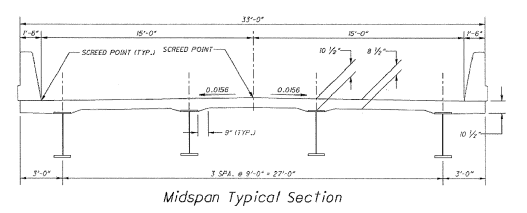
concrete I beam bridges. Screed elevations should be provided in the plans for
all curb lines or deck edges, profile grade points, transverse grade-break
lines and phased construction lines for the full length of the bridge. Bearing
points, quarter span points, mid-span points and splice points, as well as any
additional points required to meet a maximum spacing between points of 25’-0”,
should be provided in the plans. Screed elevations above each beam/girder line
are no longer required by the ODOT
Bridge Design Manual due to the differential deflection between
beam/girders. The amount of beam/girder deflection that occurs due to the wet
weight of concrete at each screed cross-section will vary based on the span
length of each beam/girder, the magnitude of concrete load applied to each
beam/girder and the size of each beam/girder cross section.
Screed Elevations are control
elevations for concrete deck finishing machines that represent the theoretical
deck surface locations prior to deflections caused by deck concrete placement
and other anticipated dead loads. Screed elevations are provided to ensure the
bridge deck is completed to the correct elevations.
Top of Haunch Elevations
represent the theoretical location of the bottom of the deck above the beam/girder
haunch prior to deflections caused by deck placement and other anticipated dead
loads. Elevations must be taken on the end dams and at every point on the beams
required for setting the grade of the screed rail, including points over the
piers. There should be no deflections at the bearing points over the piers and
abutments, with the maximum deflections occurring at the mid-spans. The Haunch
Height (Haunch Fill) equals the Top of Haunch Elevation (Deck Bottom) minus the
surveyed Beam Top Elevation. These elevations provide the contractor the means
to determine the proper haunch depths for setting deck falsework.
See Figure 511.A.
|
Beam Row |
Elev. |
Rear Abut |
¼ Pt |
½ Pt |
¾ Pt |
Pier 1 |
|
A |
Deck Bot |
966.64 |
966.48 |
966.32 |
966.16 |
966.00 |
|
Beam Top |
956.97 |
965.82 |
965.68 |
965.5 |
965.33 |
|
|
Haunch Ht |
0.67 |
0.66 |
0.64 |
0.66 |
0.67 |
|
|
B |
Deck Bot |
|
|
966.42 |
|
|
|
Beam Top |
|
|
965.77 |
|
|
|
|
Haunch Ht |
|
|
0.65 |
|
|
|
|
C |
Deck Bot |
|
|
966.52 |
|
|
|
Beam Top |
|
|
965.87 |
|
|
|
|
Haunch Ht |
|
|
0.65 |
|
|
|
|
D |
Deck Bot |
|
|
966.42 |
|
|
|
Beam Top |
|
|
965.76 |
|
|
|
|
Haunch Ht |
|
|
.66 |
|
|
|
|
E |
Deck Bot |
966.64 |
966.48 |
966.32 |
966.16 |
966.00 |
|
Beam Top |
965.97 |
965.82 |
965.66 |
965.50 |
965.33 |
|
|
Haunch Ht |
0.67 |
0.66 |
.66 |
0.66 |
0.67 |
Table
511.A – Determining Haunch Height
This is an acceptable method
of recording this information.
The Final Deck Surface Elevations
shown in the plans represent the deck surface location after all anticipated
dead load deflections have occurred. These elevations should line up with the
approach slab and pavement elevations off of the bridge. Whenever the profile
grade of the deck is adjusted, this must be considered when setting the grade
for the approach slabs and pavement in order to provide a smooth transition.
Even though it has not been necessary to adjust the grade, the as-built grade
of the deck should be used to establish the grade of the approach slabs, since
the actual dead load deflections may vary from the calculated deflections shown
on the plans.
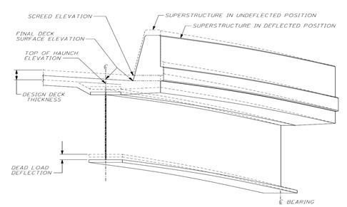
Figure 511.A – Deck Elevations and Deflections
Figure
511.B – Screed Points at curb lines, profile grade and grade- breaks
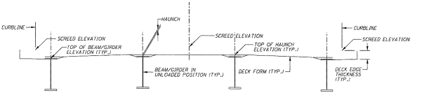
Figure
511.C – Top of Haunch Elevations in Non-Deflected (Unloaded) Position
Differential deflection
should be built into the Camber Diagram.
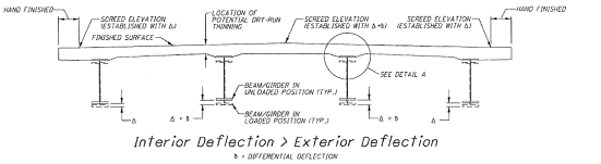
Figure
511.D – Interior Deflection > Exterior Deflection
Will occur
with addition of concrete weight.
Do not adjust screed rails to increase deck and cover thickness at interior of
deck.
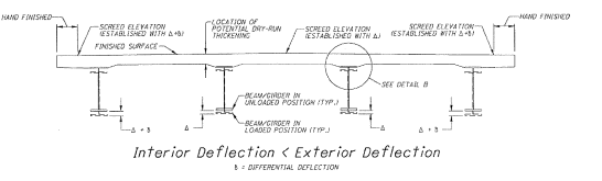
Figure
511.E – Interior Deflection < Exterior Deflection
Will occur
with addition of concrete weight.
Do not adjust screed rails to decrease deck and cover thickness at interior of
deck.
Superstructure Framing, Setting Falsework,
Setting Screed Rails and Dry Run
The Contractor’s carpenter foreman
should use the following procedure when setting the deck falsework, setting the
screed rails, and performing the dry run with the Engineer:
1. Ensure all superstructure framing, (e.g., each
intermediate crossframe and diaphragm), is permanently fastened according to
C&MS 513.26.
2. Once beam/girder erection is complete, mark the
elevation control locations on the top of the beam/girder flanges.
3. At each control location, survey and record the top of
beam/girder elevation
4. Calculate the haunch depths at each control location
as the difference between the plan Top of Haunch Elevation (Deck Bottom), and
the surveyed Beam Top Elevation.
5. Using the haunch depths and screed elevations, erect
the deck falsework. The bottom deck form in the overhangs shall be set by
subtracting the deck edge thickness from the nearest screed elevation.
6. With the falsework in place, mark the screed elevation
control locations on the surface of the falsework.
7. Set the screed rail elevations at control locations
given in the plans using the screed elevations provided. Intermediate rail
elevations may be determined by stringline between plan
specified screed locations.
8. Once the finishing machine setup is complete, run the
unit the full length of the screed rails and back using the machine’s weight to
take out any “timber crunch” or formwork settlement. Reset screed rail as
necessary.
9. Locate the finishing machine at each screed rail
control location with the carriage moved nearest the screed rail. Measure and
record the screed rail elevation. The difference between rail elevations with
and without the finishing machine represents the deflection due to the weight
of the finishing machine. Each screed elevation should be adjusted upward by
the measured deflection. Measured deflections of 0.25” or less may be ignored.
10. Starting at the beginning of the pour, locate the
finishing machine at each screed cross-section and center the paving carriage
above the interior screed elevations (e.g. crown points, profile grade lines,
etc.) Adjust the finishing machine crown such that the elevation of the bottom
of the paving rollers equals the screed elevation at that location.
11. Record the magnitude and direction of the crown
adjustment necessary when moving the finishing machine from one screed
cross-section to the next.
12. During placement, when the vertical crown adjustment
is 0.25” or less, the total crown adjustment shall be made at the midpoint
between adjacent screed cross-sections. For greater total adjustments, half of
the total adjustment shall be made at the first quarter point between adjacent
screed cross-sections and half at the third quarter point between adjacent
screed cross sections.
13. Using the cross-slope adjustments noted for each
screed cross section, move the carriage to locations above each beam/girder
line and above each mid-bay. Measure and record the distance from the surface
of the formwork to the paving rollers and verify concrete/rebar clearance.
14. When the thickness or cover does not meet plan
requirements, verify the following:
a)
Are screed rail
elevations set properly?
b)
Are haunch depths
correct?
c)
Are overhang
thicknesses correct?
d)
Do crown point elevations match screed elevations?
e)
Were rail
elevations adjusted for weight of machine?
f)
Are the reinforcing steel chairs set to the
correct height?
g)
Is there a plan error for screed elevations?
15. If each of the preceding items are
in order, differential deflections between beams/girders in the screed cross
section may be involved.
DO NOT adjust screed rail
elevations.
Use CA-S-22
Dry Run Form as a template.
When a closure pour is
specified, the designer assumes that the finished elevation of the existing
deck is correct. Due to conditions
beyond his control or conditions he has overlooked, the finished elevation of
the deck may not be as he assumed. If
this condition exists, it should be detected prior to placing the widened or
second portion of the deck. Therefore,
prior to placing the widened or second portion of the deck, the Contractor
should check the finished elevation of the existing portion of the deck to
ensure that it is correct. If it is
determined that the finished elevation of the existing portion of the deck is
not correct, the Office
of Structural Engineering should be contacted for additional
instructions.
Slipform
Construction of Bridge Railing (511.08)
In lieu of conventional
forming, the Contractor may be permitted to slipform the parapets. This
operation is accomplished with concrete that has a slump of around ±1 inch.
Prior to placing the
concrete, the Contractor must take additional measures to tie the reinforcing
steel in order to prevent it from dislocating during the slipforming operation.
If these measures are not taken, the slipforming operation will cause the
reinforcing steel to move out of its proper location.
Due to the low slump, many
times the Contractor will attempt to add water to the mix as it comes down the
chute from the concrete truck and enters into the hopper of the slipforming
machine. This is not allowed since it
will result in concrete of inferior quality.
During the slipforming
operation, small amounts of concrete will drop from the edge of the deck and
onto the surface below the bridge. If
the slipforming operation takes place directly over a traveled roadway, the
Contractor should furnish all necessary platforms to protect the traffic from
falling concrete. These platforms will
allow access to complete the finishing operation and facilitate inspector
access.
The Contractor should take
steps to ensure that the finished concrete meets the specified tolerances. These steps should include adequately tying
the reinforcing steel, determining the proper slump, and properly setting up
the slipforming machine. Failure to meet
the specified tolerances could result in the rejection of the parapet.
Any defects such as cracking,
tearing, or honeycombing should be repaired immediately. Occasionally, when repairing defects, the
Contractor will not completely fill the defect with concrete, but will only
bridge over the defect by placing the concrete on the surface of the
parapet. This is not acceptable. The
Contractor should take steps to ensure that the defect is completely filled
with concrete.
Normally, a small amount of
hand finishing is required after the concrete has been formed. Hand finishing can be difficult due to the
low slump of the concrete. To facilitate
finishing the concrete, many times the Contractor will sprinkle water or
evaporation retardant onto the surface of the concrete. The use of these substances to aid in hand
finishing is not allowed since it will only result in a surface that is subject
to scaling in the future. The contractor should not broom finish the surface.
After the concrete has
initially set, it is important to saw the control joints to the plan depth into
the parapet as soon as possible. Any
delay in performing this operation will result in additional shrinkage cracks
in the parapet.
Construction
Joints (511.09)
The surface of construction
joints should be even and have coarse texture such as produced by a wood float
on fresh concrete. Vibrated concrete
with a closed level surface is satisfactory.
Where the construction joint terminates at an offset in the concrete
surface, such as between the fascias of the deck slab and the sidewalk, the
joint should be finished neatly at the corner with a wood float.
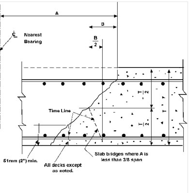
Transverse joints as
permitted in 511.09,
or longitudinal construction joints placed in deck slabs of steel beam or
girder bridges, are constructed with keys located between the reinforcing mats
and having a depth of 3/4 inch (19 mm).
If the Contractor desires a longitudinal construction joint due to an
excessive slab width and because it is not provided by the plans or
specifications, the request must be submitted to the Office
of Structural Engineering for review.
Work
Stoppage (511.10)
During the placing of a deck,
unexpected difficulties may occur that halt further placing. These may be a sudden shower, a breakdown in
the concrete plant or the finishing machine, or other unforeseen interruptions.
When a shower occurs, no
manipulation of concrete should be performed other than channeling the concrete
that was last deposited so that water will not pond on the concrete and run
back on the finished or partially finished surface. The textured surface should be covered with
the curing material as rapidly as possible.
Non-textured surfaces should be covered with polyethylene sheeting. After the shower, all ponded water should be
removed from the concrete and out through the forms before resuming placing and
finishing operations. The last surface
covered with the curing material should be inspected. If it has been marred,
the texture should be restored.
Investigate stoppages
immediately. If it is found that it will
not allow resumption of concrete placing in sufficient time, a bulkhead must be
placed immediately. If practical, the
location should not be over a pier. The
emergency bulkhead may consist of a wood strip laid across the top of the
longitudinal reinforcing bars. This
strip should be as deep as the plan cover, usually 2-1/2 inches (64 mm). Kickers can be used to secure the strip or
shims inserted between the bars in order to obtain proper crown and grade. The concrete below the wood strip should be
compacted to approximately a 45 degree slope and all excess removed as far from
the joint as possible and disposed of before it hardens. After the concrete has set, but still
fractures easily, the bottom edge should be broken to provide a vertical face
below the bottom reinforcing steel. This
may be accomplished with a pry bar prying up from the forms. Exercise care to
ensure the surface of the forms is not damaged.
See Figure 511.G - Emergency Bulkhead.
Figure
511.F – Emergency Bulkhead
Depositing
and Curing Concrete During Cold Weather (511.12)
Heated concrete and
protection must be provided whenever concrete is placed at an atmospheric
temperature of 32 °F (0 °C) or lower or whenever weather forecasts predict
temperature below 32 °F (0 °C) within the curing period. Concrete must not be placed in contact with
material having a temperature of less than 32 °F (0 °C).
The official U.S. Weather Bureau forecast for any curing
period generally can be obtained from the District Office. This information also can be obtained from
some local airports and radio stations.
When the 5-day weather forecast
does not predict 32 °F (0 °C) or lower temperatures at any time during the
period, the Contractor should not be required to erect enclosures or to use
insulated forms. However, during the
fall, winter, and spring, adequate material and equipment should be on hand to
provide for unpredicted temperatures below 32 °F (0 °C).
To ensure freedom from
freezing until protection can be established, the temperature of concrete
should not be less than the minimum of 50 °F (10 °C) specified, but should not
exceed 90 °F (32 °C) maximum. Concrete
placed at low temperatures above freezing develop higher ultimate strength and
greater durability than concrete placed at higher temperatures. Higher temperatures require more mixing
water, cause slump loss, possible quick setting, and increase thermal
shrinkage. Rapid moisture loss from hot,
exposed concrete surfaces may cause plastic shrinkage cracks. It is recommended that the temperatures of
fresh concrete, as placed, be kept as close to the 50 °F (10 °C) minimum
temperatures as practicable. When the
air temperature is 32 °F (0 °C) or lower, it is necessary to raise the
temperature of the concrete by heating the mixing water or aggregate or both. The concrete must be protected from freezing,
and specified curing temperatures must be maintained by a heated enclosure,
insulated forms, or by either of these in combination with flooding.
Decks slabs less than 10
inches (254 mm) thick must be protected from freezing, and specified
temperatures maintained for the curing period by a heated enclosure.
Arrangements for covering and
insulating newly-placed concrete must be made in advance of placement and
should be adequate to maintain the specification temperature in all parts of
the concrete.
During the first few days which
require protection, most of the hydration heat of the hardening cement is
developed. As a result, if heat generated in the concrete is adequately
conserved, outside heat generally is not required to maintain concrete at the
correct temperature. This heat may be
conserved by using insulating blankets and insulated forms where repeated reuse
of forms makes this practical. Outside temperatures at concrete walls, piers,
abutments, or slabs above ground may be protected with insulation under various
conditions (see chart to follow). On
work where protection by insulation is permitted, project personnel should
check the protection proposed by the Contractor and be reasonably sure that the
proposed insulation is adequate for the expected exposure before concrete
placement is permitted to begin.
The application of insulation
should be as follows:
1.
Blanket
insulation is applied tightly against wood forms with nailing flanges extending
out from the blankets so they can be stapled or battened to the sides of the
framing. Seal the ends of the blankets
by removing a portion of the mat and stapling or battening the blanket to
headers to exclude air and moisture.
Corners and angles are most vulnerable.
Take extreme care to ensure they are well insulated and the insulation
is held firmly in place.
2.
In case of steel
forms, the insulation should be applied tightly against the form and held
securely with the ends sealed to exclude air and moisture.
3.
Where
practicable, the insulation or insulated form should overlay any cold concrete
previously placed by at least 1 foot.
4.
Any tears in the
liner are to be repaired immediately with accepted waterproof material.
5.
Where tie rods
extend through an insulated form, a plywood washer, approximately 3/4 × 6 × 6
inches (19 x 150 x 150 mm), should be placed on top of the insulation blanket
and secured in a satisfactory manner.
6.
The tops of all
pours must be covered with insulating blankets, except for areas around
protruding reinforcing bars that may be insulated with straw or wrapped with insulation
blankets. Waterproof covers should be
used to cover the top of such pours, as required by specifications.
7.
Protective
enclosures may be constructed of canvas, plywood, polyethylene, plastic, etc.
in such a manner that will maintain uniform temperatures and allow free
circulation to the warmed air.
8.
For the underside
of deck slabs, 3/4 inch (19 mm) plywood forms have an equivalent thickness of
0.6 inch (16 mm) and will provide protection of 32 °F (0 °C) minimum air
temperature.
9.
Close packed
straw under canvas may be considered a loose fill type if wind is kept out of
the straw. The insulating value of dead
air space greater than about 1/2 inch (13 mm) thick does not change greatly
with increasing thickness.
Heated Enclosure (511.12.A)
When salamanders or other
heaters supply heat, local drying and burning of the forms may result and
necessitate moving or adjustment of the setup.
Regular observance of the forms and burlap should be made to ensure that
the concrete is kept wet for the duration of the curing period, as required in 511.14. Combustion type heating units shall be vented
from the enclosure to preclude damaging fresh concrete. The enclosure should
surround the top, sides, and bottom of the concrete to be placed during cold
weather.
Temperature Control
Thermometers for use in
enclosures should be the high-low recording type and be furnished by the
Contractor. If the enclosure is long or
high, more than one thermometer may be required. The readings in the morning and the afternoon
normally represent the low and high temperature respectively; carefully select
the time when the high-low recording thermometers are checked.
When insulated forms are
used, the thermometer must be furnished and installed by the Contractor. They must be capable of indicating surface
temperature of the concrete. In case of
a tall section, such as pier shafts or retaining walls, more than one
thermometer will be required because of the temperature gradient. Temperatures should be read twice daily for
high and low readings. When insulated
forms are used, temperature of concrete will cause a lag in the temperature
change of the surrounding air. Time of
observance need not be as selective for representing the high and low, but is
used to indicate a trend that may require venting of the forms or erecting an
enclosure. When venting of a vertical
form is necessary, it should be raised slightly at the bottom to create a
chimney effect.
The temperature record must
include the required temperature readings for the entire curing period. Outside air temperatures may be local
reported temperatures.
Temperature and control
methods used, as well as temperature readings, must be recorded on the Inspector’s
Daily Report.
Cold Weather Curing
Time
To fulfill the curing
requirements for concrete placed in cold weather, the surface temperature must
be maintained as specified in 511.14
or be exposed to ambient air temperatures no less than 50 °F (10 °C) for 5
days.
In case any day’s temperature
readings fall below the minimum specified, the duration of heating must be
extended to provide the required number of days. In case of loss or breakage of thermometers,
replacements or other provisions must be made to provide a complete record.
Removal
of Forms (511.13)
Falsework must not be removed
until after the time-temperature requirements of 511.14
are met or satisfactory beam tests are attained. During cold weather, forms are to be removed
after the curing period in such a manner that the temperature of the concrete
does not drop more than 20 °F (7 °C) in any 24-hour period.
Note 1 in Tables
511.14-1A and B states that span is defined as the horizontal distance
between faces of the supporting elements when measured parallel to the primary
reinforcements. For slab deck bridges,
the primary steel runs longitudinally down the deck. For beam supported structures, the primary
steel runs transversely across the deck.
Curbs and Parapets
Forms for curbs and parapets
should be observed carefully for condition of surface, flush fit of panel
joints, proper installation of bevel strips, and visual and measured alignment
and elevation. Adequate form supports
should be provided to ensure proper position of concrete during and after
placement. Surface rubbing does not
justify the use of inferior forms or lack of adequate supports.
When expansion devices are
used to allow for bridge deck expansion, more open space for expansion must be
provided in the curb and parapet than is required for expansion devices. Where conduits cross this opening, give
special attention to clearance for expansion fittings to ensure free movement
of the deck.
Transverse joints may be
placed in the sidewalk or curb section near the center of any span.
Curing and Loading (511.14)
Curing is governed by 511.14
that requires either Method A, Water Curing or Method B, Membrane Curing. Curing time is 7 days. No curing is required
for surfaces covered by forms for the duration of the curing period. Concrete that will be overlaid with concrete
or sealed, as well as all superstructure concrete, must be cured in accordance
with Method A, Water Curing. The top
surface of superstructure deck concrete must be cured for 7 days in accordance
to Method A and then cured within 12 hours in accordance with Method B. Do not
shorten the minimum required Method A curing time
regardless of strength gain.
The curing material must be
applied as soon as possible to avoid cracking of the concrete. Application of the curing material should be
applied immediately after the finishing operation is complete.
When it is necessary to work
on concrete during the curing period, such as placing deck concrete adjacent to
a construction joint, only the area immediately adjacent to the joint should be
exposed and the remaining area protected from damage by the workers. Plywood sheets may be used for
protection. The exposed area should be
kept moistened until adjacent work is complete, after that, the cover should be
restored and normal cure resumed.
Floor forms provide the cure
for the underside of the slab and are not to be removed before the end of the
curing period.
Method A, Water
Curing (511.14.A)
When two thicknesses of
burlap are used to water cure the concrete, they should be kept wet by the continuous
application of water from soaker hoses or other sprinkling devices during the
required period. In lieu of continual
sprinkling devices, white polyethylene sheeting or wet plastic coated blankets
may be used to cover the concrete.
On bridge decks, a single
layer of wet burlap is kept wet by a continuous application of water and
covered by white polyethylene. The polyethylene should be placed
transversely. The edges should be lapped
and held securely to maintain a moisture seal.
The curb area may be covered with a longitudinal strip that is held
securely to the fascia form and laps the transverse strips. A continuous batten may be used to seal the
blanket to the form and reinforcing bars may be laid on the laps to make the
seal. Check areas suspected of having
the seal broken during subsequent work or weather disturbances. If these areas
are found to be drying out, soak the burlap and reseal the white polyethylene.
Plastic-coated blankets must
be inspected prior to use to ensure that they are sound and will retain the
moisture required to cure the concrete.
All holes and tears must be repaired so that they are watertight. The material should be rejected if defects
are numerous and repairs are questionable or if the plastic coating has cracked
from aging.
Burlap and plastic-coated
blankets must be thoroughly soaked with water prior to placing on the surface
of the concrete. Dry material placed on
the surface of the concrete will draw moisture out. This will increase the
chances of drying shrinkage cracks. If
new burlap is used, extra measures may need to be taken to ensure that it is
properly soaked since it doesn’t soak up water as well as used burlap. If burlap to be soaked is delivered to the
project in a tightly wrapped condition, it should be loosened to allow the
penetration of water.
Method B, Membrane
Curing (511.14.B)
The concrete curing membrane
is white-pigmented material meeting specifications 705.07. The material may be either Type 1 (clear or
translucent without dye) or Type-D (clear or translucent with fugitive dye).
The membrane should be
applied in one or more separate coats by spraying a fine mist at a uniform
application rate of one gallon per 200 square feet (70.3 square meters) of
surface. The rate of application is
controlled by laying out in advance, on the surface to be cured, an area that
will be properly covered by the number of gallons of compound in the spray
container. The procedure helps ensure
that the membrane is applied at not less than the required rate.
Loading Requirements
for QC/QA Concrete
See Table
511.14-1 in C&MS
511. Falsework may be removed from any span and all piers caps, and the
concrete open to traffic when the compressive strength of sample cylinders is
greater than or equal to 0.85 percent f’c or the flexural strength of sample
beam is greater than or equal to 650 psi. Per Supplement
1098, the maturity curve method may be used for determining strength of the
concrete. Do not shorten the minimum required Method A
curing time regardless of strength gain. When placing concrete for a
superstructure between October 15 and March 15, open the deck no sooner than 30
days after placement.
Loading Requirements
for Non QC/QA Concrete
See Table
511.14-2 in C&MS
511. No traffic is to be permitted on a structure until the concrete has
attained the age specified in 511.14. For all spans, this is 14 days without a beam
test or 7 days with satisfactory beam test. Do not shorten the minimum required
Method A curing time regardless of strength gain. When
placing concrete for a superstructure between October 15 and March 15, open the
deck no sooner than 30 days after placement.
Loading of Completed
Structure Units
No load is to be applied or
work conducted that will damage new concrete.
This applies to loading or work on any part of the structure that will,
in the opinion of the Engineer, cause damage.
Usually this criterion will permit work on a footing after 36 hours (or
sooner) with a successful beam test, of normal curing, where bending stresses
will not occur.
Surface Finish (511.15)
Patching
Shortly after the removal of
forms, all cavities produced by form ties and all other holes, honeycomb spots,
broken corners or edges, and other defects (except air bubble holes that may be
filled by grout cleaning) must be cleaned. After being saturated with water,
all cavities shall be completely filled, pointed, and trued with a mortar of
the same proportions used in the concrete being finished.
On all exposed surfaces, all
fins and irregular projections must be removed with a stone or power grinder,
taking care to avoid contrasting surface textures. Sufficient white cement must be substituted
for the regular cement in the filling of holes and other corrective work to
produce a finished surface of the same color as the surrounding concrete.
If shown on the plans,
exposed surfaces that have an appearance not satisfactory to the Engineer shall
be grout cleaned in a manner satisfactory to the Engineer.
The Contractor should be
advised that it will be necessary to use good formwork to obtain satisfactory
surfaces.
Grout Cleaning (511.15.A)
Grout cleaning shall be
performed as outlined in 511.15.
Rubbed Finish (511.15.B)
When specified on the plans,
rubbing shall be performed as outlined in 511.15.
Forms should be removed
within 2 days after the concrete is placed.
Exceptions are the slab fascia form on which other fascia forms are set
and wall forms that overlap a joint. If parapets are placed in cold weather,
make provisions to remove forms and begin surface finishing on the day
following placing, while maintaining a minimum temperature of 50 °F (10 °C), or
postpone the placing of parapets until weather conditions are suitable for
proper performance.
Roadway
Finish (511.16)
Machine Finishing
A machine finish is required,
except for small bridges where the Engineer may waive the requirement.
Mechanized finishing machines are preferred to hand finishing methods for both
consistency of surface finish and economics. The finishing machine must be
self-propelled with forward and reverse drive. Mechanized finishing machines
are comprised of fabricated truss sections pinned together to span the bridge
deck width to be paved. The truss spans are supported at each end on a set of wheels,
called “bogies,” which ride along the length of the bridge on screed rails.
Suspended below the truss is a finishing head, called a “carriage,” which
levels, compacts, vibrates and finishes the concrete. The machine shall have
two rotating rollers, leveling augers and either a vibrating pan or vibrating
rollers. See Figure 511.H. Field verify that the
vibrating frequency of the pans or rollers is between 1,500 and 5,000 pulses
per minute. The contractor must supply the instrument to check the frequency.
The roller fins should not protrude more than 1/4 inch from the roller.
Protruding fins can mechanically depress the aggregate too far from the surface
of the concrete. The Contractor should detail the method used to support the
machine on the deck and the complete procedure for placing the slab and submit
to the Engineer for review. Supports for
the riding rails must be equipped to handle the weight of the machine in order
to avoid failure or any vertical deflection.
The concrete handling, placing, and finishing procedure should be
planned to ensure that the concrete will be placed and struck off with a
minimum of manipulation and at a sufficient rate in order to provide workable
concrete in an area adequate for proper, final hand finishing. Success of the Contractor’s procedure on
previous decks should be considered.
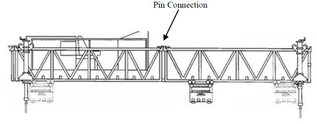
Screed Rail with Bogies (wheels) Carriage with rollers
& augers
Figure
511.G – Finishing Machine
For transverse machines, the
screed should be assembled or adjusted to the required crown established from a
taut line while suspended in the same manner as it will be in operation.
Prior to ordering concrete,
and after the finishing machine has been made ready, make a dry run over the
entire deck. Check slab thickness and
reinforcing steel cover along with crown conformance to both end dams and
expansion joints. If the rate of crown
varies, and the machine can be adjusted during operation, the required crown
should be determined at regular intervals not exceeding 25 feet (7.62 m), the
required increment of adjustment established and the location referenced on the
side of the bridge.
Plan dimensions for deck
thickness, the reinforcing of steel cover which was verified during the dry
run, and the witnessing of screed adjustments to the required crown must be
recorded in the project records. A
last-minute check that form dimensions and reinforcement have been verified and
documented should be made at this time on the Inspector’s
Daily Report. Use CA-S-22
Dry Run Form as a template.
Finishing machines can be
placed such that the truss sections are skewed with respect to the screed
rails. This orientation allows for concrete placement parallel to the
substructure skew as required by the C&MS 511.
For skew angles of 15 degrees and greater, the finishing machine can be skewed
to within 5 degrees of the plan specified skew angle. See Figure 511.I.
The carriage can also be
skewed with respect to the truss sections. This feature allows the carriage to
finish the concrete transverse to the bridge when the truss sections are placed
at some other orientation (e.g., parallel to the substructure skew). In order
to ensure a proper finish at transverse grade breaks (e.g., crown points), the
carriage should always be oriented to finish the concrete transverse to the
bridge. A special length truss section insert is required above the grade break
locations such that the grade break line lies directly below opposite corners
of the section. For skewed bridges without transverse grade breaks, skewing the
carriage with respect to the truss sections is not required. The finishing
machines can be hinged at the pin connections between truss sections in order
to provide transverse grade breaks (e.g., crown points).
![]()
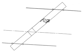
Paving Direction
Figure
511.H – Finishing machine oriented with skew
Although proper measurements
made during the dry run should ensure plan dimensions, check measurements after
the concrete is struck to grade in order to verify that the machine is still in
adjustment and reinforcing steel remains in place. Slab thickness measurements can be obtained
by probing with a 1/4-inch-straight wire (6 mm) and the cover over re-steel
with a 90 degree bent wire of the same size.
These measurements should be taken shortly after the start of the
finishing operation, and periodically thereafter, or when an area appears
questionable. Wide, flat sections such
as super elevated slopes are questionable and must be checked. The probing should be performed in plastic
concrete where it will be easier to close the void.
Some cover checks are required;
however, they do not need to be as numerous as the depth checks that also
reflect cover. It is recommended that as
many depth checks as possible be made as time permits. A statement should be entered in the project
records indicating that check measurements have been made and conform to plan
dimensions. If localized areas do not conform to plan dimensions, they should
be noted, and any corrective action documented.
During operation, a uniform
head of concrete should be maintained along the full length of the screed. Screeds should be lifted from the surface
when not in use. During operation, only
the operator is permitted on the machine.
The machine should continually be in operation as long as practical and
the concrete placing procedure should not exceed the speed of the machine.
Tracking or walking in the
screeded surface is not tolerated.
Final Finishing
It is imperative that final
finishing follow immediately behind the finishing machine. If this final finishing should fall behind,
the rate of concrete placement should be reduced.
The construction joint
surface under the sidewalk or the safety curb should not be used as a place for
finishers to stand or as a passageway for workers. Planks may be placed on the sidewalk
reinforcement providing sufficient additional ties and braces are used if
necessary to obtain a rigid framework that will not disturb the bond of the
stirrups.
Minor surface irregularities
left after screeding can be corrected with long handled floats. This operation should be held to a minimum
and any major irregularities encountered should be corrected by the use of a
straightedge. Use of water, evaporation
retardants, or finishing agents on the surface of the concrete to facilitate
finishing is not permitted. If a Contractor
adds water by continually washing his tools, require that they use a towel to
dry the tools prior to reuse.
Bridge
Deck Grooving (511.17)
The deck surface must be
textured by using a broom to provide a surface satisfactory to the Engineer.
The broom must produce a uniform, gritty texture in either the longitudinal or
transverse direction. The texturing
should take place as the pour progresses after other finishing operations have
been completed. Note: If the concrete
tears or “mud balls” are produced on the surface, the Contractor needs to apply
less pressure to the broom or wait a few minutes until the concrete has begun to
set.
After the water curing of the
concrete is complete, and either before applying curing compound, or some
period after applying curing compound, and before opening the bridge to
traffic, longitudinal grooves, parallel to the bridge centerline, must be sawed
into the surface of the deck. Apply curing compound within 12 hours after
grooving the deck. The grooves must be sawed in a continuous, uniform pattern
spaced at 3/4 inch minus 1/4 inch or plus 0 (19 mm minus 6mm or plus 0) and
must be approximately 0.15 inch (4 mm) deep and 0.10 inch (3 mm) wide. Grooves must be within 9 to 12 inches from
devices such as scuppers or expansion joints.
On skewed bridges, in order to accommodate the equipment used to saw the
grooves, the grooves must be sawed from 2 inches to 2 feet from the expansion
joint. This results in grooves with a
staggered or stepped appearance. Maintain a minimum clearance of 9 inches (220
mm) to a maximum of 30 inches (750 mm) clearance between the grooves and the
curb or parapet toe. However, at no point shall un-grooved portions of deck extend beyond
edge line and into the temporary or permanent travelled lanes.
For
staged, or phase bridge deck work, the grooves must be sawed parallel to the
final, permanent bridge centerline. If the different stages or phases of the
bridge deck work occur within one construction season, any stage opened to
traffic shall receive an interim coarse broom finish during placement. Then the
longitudinal grooves are sawed after the final stage. The interim broom finish
will not be allowed as a surface texture when opened to traffic over a winter
season. Longitudinal grooves must be sawed in the deck prior to opening to
traffic for a winter season.
For
bridge decks that widen from one end to the other, the longitudinal grooves
must be sawed parallel to the centerline of the roadway. On the side of the
bridge that widens, saw the longitudinal grooves to follow the edge line. Saw
longitudinal grooves in the gore areas, avoiding the overlapping of grooves.
Sidewalk Finish (511.18)
Float Finish
Concrete for sidewalks,
safety curbs, and tops of substructure units are struck off with a template and
finished with a float to produce a sandy texture.
Sealing Joints and Cracks (511.19)
After
curing, all cracks, transverse and longitudinal joints in the deck, joints
between the concrete deck and steel end dams, and joints between the concrete
deck and safety curbs, barriers and parapets must be sealed with high molecular
weight methacrylate (HMWM) prior to opening the deck to traffic.
Compressive Strength (511.20)
Sample
and test concrete strength according to C&MS 511.04.
Concrete Requiring QC/QA
When
the bid item requires QC/QA, the Engineer will evaluate the QC compressive test
sublot results according to Supplement
1127 to determine pay factors for structure concrete.
If
a single test result for compressive strength of a sublot of concrete is found
to be less than 88 percent f’c, the Engineer will determine the location for evaluating the
strength of the sublot represented by the low compressive strength concrete.
Nondestructive testing or coring will be performed at such locations. If the
reported nondestructive test results are greater than the specified f’c, the Engineer will accept the
concrete and use the original cylinder results for calculating the compressive
strength pay factor (PFc). If coring is performed, the
core results will be used in place of the original cylinder results for pay
factor determination.
If
the nondestructive test results are less than the specified f’c, the concrete must be cored. The
Engineer will determine the locations for the required concrete coring by the
contractor for testing by the Department. The contractor must patch core holes
with approved patching material. If the core results are above 88 percent f’c, the core strength results will be
used for calculating the compressive strength pay factor (PFc).
If
the core results indicate that the compressive strength of the concrete is
below 88 percent f’c,
the Contractor must submit a plan for corrective action to the Engineer for
approval. If the corrective plan is not approved, the Engineer will require the
Contractor to:
1. Remove and replace the
unacceptable concrete that the sublot represents and retest the new sublot at
no cost to the Department or
2. Leave the unacceptable
material in place and be paid for the sublot with a pay factor of 0.75.
If
three or more sublot compressive strength acceptance test results are less than
f’c, but greater than 88 percent f’c, the Engineer will require
an investigation by the contractor of the reasons for the consistent low
strengths. No additional placements of the concrete JMF will be made .until the
investigation is completed to the satisfaction of the Engineer. The
investigation should include all facets of the concrete operation including
batching, mixing, delivery, clean up, sampling, testing, quality control plan,
etc. If the Engineer is unsatisfied with
the results of the investigation, the JMF and the quality control plan will
become not approved. The Contractor will have to develop and submit a new JMF
and quality control plan conforming to the requirements of Supplement
1126, C&MS 499.03
and C&MS 511.04. Pay factors under C&MS 511.22
for these low strength sublots will be based on the original reported cylinder
strengths.
Concrete Not Requiring QC/QA
When
the bid item does not require QC/QA, the Engineer will evaluate the strength
results following the requirements of Table
511.22-2 and as follows:
1. If a single
compressive strength test result is less than f’c, the material will be considered unacceptable material and the
Department will determine acceptance according to C&MS 106.07.
2. If three or more
compressive strength test results are less than f’c, the Contractor will be required to perform an investigation of
the reasons for the consistent low strengths. No additional placements of the
concrete JMF will be made until the investigation is completed to the
satisfaction of the Engineer. The investigation should include all facets of
the concrete operation, including batching, mixing, delivery, cleanup,
sampling, testing, etc. If the Engineer
is unsatisfied with the results of the investigation, the JMF will become not
approved. The Contractor will have to develop and submit a new JMF conforming
to the requirements of C&MS 499.03.
Air
Content (511.21)
For concrete that requires QC/QA,
test the air content of the concrete according to C&MS 455.03. When QC/QA concrete is not required, the
Department will test the air content as directed by the Engineer.
Concrete Requiring
QC/QA
Any concrete with air results
outside the requirements of Table
499.03-1 that is placed into the structure is unacceptable material
according to C&MS 106.07. The amount of unacceptable material will be
the amount represented by the test result. The Contractor must re-evaluate the
unacceptable material, at no cost to the Department, by coring the location
containing the unacceptable concrete.
The Contractor must patch the core hole with approved material. If the
concrete had high air content, the core must be tested for compressive
strength. Concrete with a minimum
strength of f’c may be left in place.
If the concrete had low air content, the core must be tested to determine the
in-place hardened air content, specific surface and spacing factor according to
ASTM C 457. The Contractor
must remove and replace unacceptable materials with specific surface results
less than 600 in-1 (25 mm-1) or spacing factor results
are more than 0.008 in (0.20 mm). The
contractor must hire an independent laboratory, acceptable to the Department,
to perform the testing.
Concrete Not
Requiring QC/QA
Any concrete with air results
outside the requirements of Table
499.03-1 that is placed into the structure is unacceptable material,
according to C&MS 106.07. The amount of unacceptable material will be
the amount represented by the test result. The contractor must re-evaluate the
unacceptable material, at no cost to the Department. The Department will core
the location containing the unacceptable concrete. The contractor must patch
the core hole with approved materials. If the concrete had high air content,
the Department will test a core for compressive strength. Concrete with a strength
of f’c may be left in place. If the
concrete had low air content, the Department will determine the in-place
hardened air content, specific surface and spacing factor according to ASTM C 457. The contractor
must remove and replace unacceptable materials with specific surface results
less than 600 in-1 (25 mm-1) or spacing factor results of
more than 0.008 in (0.20 mm).
Pay Factors (511.22)
Apply pay factors as follows:
Concrete Requiring QC/QA
The Department will use pay factors based on the
percent within limits (PWL) to establish a final adjusted price. The PWL will be established per lot(s)
accepted in the QCP for each bid item quantity of concrete. The Department will calculate a PWL according to Supplement
1127 using either the Contractor’s verified QC compressive test results or
core results when the QC could not be verified.
The compressive strength pay factor (PFC)
from Table
511.22-1 for the lot will be applied to each bid item represented in the
lot. The Department will combine approach
slab and deck concrete test results in the same lot to determine final pay
factors.
If the PWL value
determined for the lot of concrete is below 75%, the contractor must submit a
plan for corrective action to the Engineer for approval. If the corrective plan
is not approved, the Contractor must remove and replace the lot of unacceptable
material, at no cost to the Department, or leave the unacceptable material in
place and be paid for the lot of with a pay factor of 0.75.
Concrete Not Requiring QC/QA
For concrete items that the Department performs
compression testing, the Department will use a pay factor of 1.00 based on the
individual compressive strength results greater than or equal to f’c for the quantity represented by the
test results. If the compressive
strength results are less than f’c,
that material represented by the test result is unacceptable material,
according to C&MS 106.07.
See Table
511.22-2.
Method of Measurement (511.23) and Basis of Payment (511.24)
The quantity of concrete for
every reference number will be determined from the plan dimensions, in place,
complete, and accepted with adjustments made for necessary changes or
errors. Plan dimensions shall be verified
and recorded.
The final quantity for
structure concrete is rounded off to the unit for the item that is listed in
the proposal. Where plan dimensions are
in inches (mm), these should be converted to feet (m) and carried to a decimal
place that will not affect the accuracy of the final unit.
Calculations made for
necessary changes or plan errors are to be identified properly with the
structure unit and reference number and to be validated by the signature or
initials of the person who made the calculations and the date they were made.
The Department will calculate
separate quantities of concrete due to unacceptable compressive strength per 511.20
and air content per 511.21.
The Department will initially
pay the full bid price to the Contractor upon completing the work. The Department will
calculate the final adjusted payment for each item as follows:
PF1 - The final adjusted pay per cubic
yard (cubic meter) or square yard (square meter), for accepted quantities of
concrete:
PF1 = (Contract Bid Price) x
PFC
PF2 - The final adjusted pay per cubic
yard (cubic meter) or square yard (square meter) for unacceptable quantities of
concrete due to compressive strength or low air content and allowed to stay in
place, according to 511.20
or 511.21.
PF2 = (Contract Bid Price) x
0.75
Calculate the adjusted price per bid item
by multiplying PF1 or PF2 by the appropriate quantities of concrete, then sum
the values. Subtract the full bid price paid to the Contractor from the
adjusted price to determine the difference. The Department will execute final
adjustments by change order upon receipt of all test data.
Documentation Requirements - 511 Concrete for Structures
Contractor has to submit an
accepted Concrete Job Mix Formula (JMF) 10 days before placing concrete.
For QC/QA Concrete, the
Contractor has to submit a Quality Control Plan (QCP), according to the
requirements in C&MS 455.02
and 455.03.
For Mass Concrete, the Contractor
has to submit a Thermal Control Plan (TCP), according to the requirements in
C&MS 511.04.A.
The TCP shall include:
1.
Duration and
method of curing.
2.
Procedures and
equipment to control concrete temperature and differentials.
3.
Temperature
sensor types, locations, installation details, monitoring system, operation
plan, and a remedial action plan.
4.
Criteria for form
removal to control the maximum temperature differential.
The Contractor must provide
and maintain a Concrete Cylinder Curing Box.
Prior to concrete placement:
1.
Engineer received
advance notice from contractor placing concrete
2.
Form dimensions and
elevations field verified.
3.
Forms clean and
oiled.
4.
Re-steel placed
according to 509.04.
5.
Contractor has
proper equipment for placement, vibration, finishing and curing.
6.
If QC/QA
concrete, the Contractor has QC staff to sample and test concrete.
7.
Forms and
reinforcing steel heated to minimum 32 ºF (0 ºC) prior to placing concrete
8.
For deck, depth,
and finishing machine operation documented on Dry Run Form (Use CA-S-22
as template)
9.
Place
superstructure concrete when air temperature is 85 ºF (29 ºC) or less and not
predicted to be above 85 ºF (29 ºC) during placement.
10. Prepour meeting forms CA-S-4
and CA-S-6.
During and after concrete
placement:
1.
Placement and testing requirements documented
on forms CA-C-1
and TE-45.
2.
Record surface
temperature inside of cold weather protection.
3.
Evaporation rate
as per 511.07.
4.
Concrete
vibrated.
5.
On deck, document
depth obtained after final screed strike-off on day of pour.
6.
Finish deck as
per 511.16.
7.
Amount of curing
compound used and/or method of curing per 511.14.
8.
Loading, and
removing falsework as per 511.14.
9.
Document the sawing of longitudinal grooves on
deck surface as per 511.17.
10. All joints and cracks sealed per 511.19.
11. Smoothness requirements are outlined in 451.12
and Proposal
Note 555. A profilometer will be
required to check smoothness.
12. Placement tolerances met per 511.07
or 511.08.
13. Compressive strength of samples met requirements per 511.20.
14. Air content requirements met per 511.21.
15. Pay factors calculated per 511.22.