621 Raised Pavement
Markers (RPM)
General
This information is intended
to serve as a guide for construction personnel where the Contractor furnishes
and installs raised pavement markers. However,
it may be useful for maintenance personnel performing the same functions. Inspection procedures are outlined. This information points out the various
important features and references the applicable specification or standard
drawing.
Conduct 25 percent to 75
percent inspection during the installation activities, which include daily
start-up, intermittent, and end of day inspection. Additionally, conduct 80 percent to 100
percent inspection of all installed RPMs prior to
final acceptance.
Materials (621.02)
Make sure that all RPM
materials used on projects are approved and listed on the Qualified
Product List at the following website:
Item 721.01
Raised Pavement Marker Castings
http://www.odotonline.org/materialsmanagement/qpl.asp?specref=721.01
Item 721.02
Prismatic Reflectors
http://www.odotonline.org/materialsmanagement/qpl.asp?specref=721.02
Item 721.03
Raised Pavement Marker Castings Adhesive
http://www.odotonline.org/materialsmanagement/qpl.asp?specref=721.03
Item 721.04
Prismatic Reflectors Adhesive
http://www.odotonline.org/materialsmanagement/qpl.asp?specref=721.04
Installation RPM Casting (621.04)
References:
1. Brochure for
RPM Installation Procedure.
2. See Traffic
Engineering Manual, Section 350-3 at the following website:
RPMs shall be placed when the pavement surface temperature
and the ambient air temperature is at least 40 °F (5 °C) and the pavement is
dry.
RPMs shall not be placed under the following conditions:
1. On pavement surfaces with cracking, spalling, or
failure of underlying base material.
2. Within 1 foot (0.3 m) of active signal detector loop
wires.
3. Over pavement markings, except with the Engineer’s approval.
4. Closer than 2 inches (50mm) to a pavement construction
(transverse or longitudinal) joint or within an intersection.
5. Within 3 feet (1 m) of a bridge expansion joint.
Procedure for RPM
Casting Installation:
1. Casting installation.
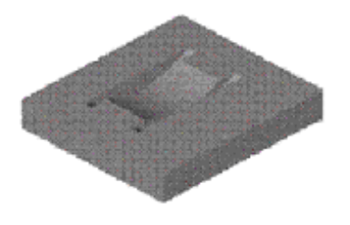
Figure
621.A – Typical Saw Cut
a. Pavement must be cut to the dimensions for the casting
being used.
2. Casting in saw cut without epoxy.
a. Each pavement cut must be inspected prior to adding
epoxy.
b. When a casting is inserted in the cut without epoxy,
all four leveling lugs/tabs must contact the pavement surface.
All
four keel-ends of castings must be below the surrounding pavement surface.
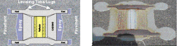
3. Casting centered in saw cut lengthwise.

a. Each casting must be centered lengthwise and should
have 1/8-inch (3 mm) clearance between pavement cut and casting for epoxy to
bond properly.
b. Only the leveling lugs/tabs should be in contact with
pavement surface after insertion of casting in pavement so that a minimum of
1/8 inch (3 mm) of epoxy is the bonding adhesive between casting and pavement.
c. The pavement cut must be completely dry and free of
dust, dirt, or any other material that will interfere with the adhesive bond.
d. Epoxy on the active reflector face must be removed
immediately.
e. Saw cut – casting fit must be periodically checked as
saw blades wear to ensure correct dimensions are maintained.
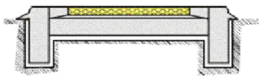
4. Properly installed RPM with epoxy around casting.
a. Two component epoxy adhesive approved (must be on QPL) is to be used to fill the pavement cut to within
3/8 inch of top of pavement cut prior to placing casting.
b. After placing casting:
The four leveling lugs/tabs
must be in contact with pavement surface.
The epoxy should ooze out
from under the casting of all sides, filling all voids around the casting, and
be level with pavement surface.
Reflector Replacement (621.06)
References:
1. Brochure for
RPM Installation Procedure.
2. See Traffic
Engineering Manual Section 350-3 at the following website:
http://www.dot.state.oh.us/Divisions/Operations/Traffic/publications2/TEM/Documents/Part_03_Complete_042012Revision_bookmarked_042012.pdf
Procedure for Reflector Replacement:
1. Remove reflector.
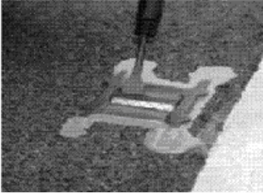
a. Pry old reflector out of casting.
b. Use eye protection when replacing reflector.
2. Clean the casting.
a. Scrape old pad material and adhesive out of reflector
pocket, using an air hammer or wire brush.
b. Sandblast the casting pocket to remove all residual
adhesive, rust, and other contaminants from the casting.
c. It is important that the casting is clean to ensure
long-lasting performance.
3. Apply adhesive.
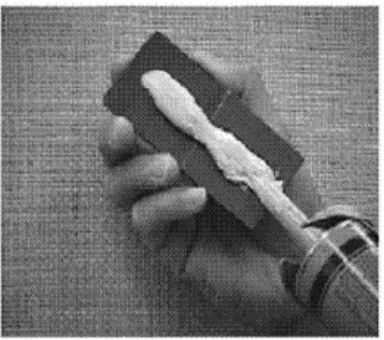
a. Peel the release liner from the back of the reflector.
b. Apply a wide bead, approximately 3/8 inch, of an
adhesive (as approved ODOT
QPL) in the center of the adhesive pad on the
back of the reflector.
4. Install reflector into casting.
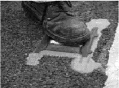
a. Place the reflector into the casting pocket.
b. Apply foot pressure on the reflector for 1 to 3
seconds.
c. Adhesive must flow out around all edges of the
reflector to indicate that the adhesive completely covers the entire bottom of
the reflector and provides a uniform adhesive layer between the reflector and
the casting.
Remedial Actions for Poorly Installed RPM Castings
This information is intended
to serve as a guide for construction and/or maintenance personnel where the RPM
castings are poorly installed. It provides a guide to the necessary remedial
action to fix the problem.
The RPM casting shall be
installed properly according to the following references:
1. Item 621.03,
“Layout.”
2. Item 621.04,
“Installation of RPM Casting.”
3. Standard
Construction Drawings TC-65.10
and TC-65.11.
The following information
provides examples of defectively installed RPM castings and describes remedial
action to fix the problem.
Defective Installation: The RPM is installed with all four lugs/tabs not
resting on the pavement as shown in Figure 1 below:
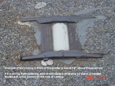
Remedial Action:
Remove and reinstall the RPM
casting at a new location.
New RPM location shall not
exceed 25 percent of the specified RPM spacing.
If necessary to relocate the RPM
to a distance greater than 25 percent of the RPM spacing, do not install the
affected RPM.
Fill the old cavity on the
roadway surface with epoxy or asphalt concrete from where the RPM casting is
removed.
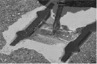
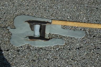
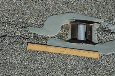
Defective installation: The RPM is installed, but does not fill the voids
with epoxy around the casting or the RPM is installed, but the epoxy is not
around the casting to the surface of the pavement as shown in Figure 2.
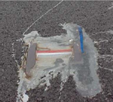
Remedial Action:
Blow out dirt from around
casting with compressed air.
Fill the voids and seal the
RPM casting all around with epoxy as shown in Figure 3.
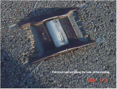
Defective installation: The RPM casting is installed near or on a
longitudinal joint or crack on the roadway surface as shown in Figure 4.
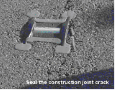
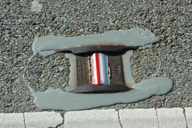
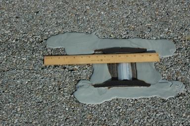
Remedial Action:
Seal all the cracks with
epoxy up to 9 inches from the RPM casting as shown in Figures 5, 6, and 7.
Defective installation: The RPM is installed, but the epoxy adhesive is not hardened,
or the epoxy adhesive is not uniform gray in color as shown in Figure 8.
Remedial
Action:
Remove and reinstall the RPM
casting at a new location.
New RPM location shall not
exceed 25 percent of the specified RPM spacing.
If necessary to relocate the
RPM to a distance greater than 25 percent of the RPM spacing, do not install
the affected RPM.
Fill the old cavity on the
roadway surface with epoxy or asphalt concrete from where the RPM casting is
removed.
Defective installation: The RPM is installed on construction joints which
have extensive failure as shown in Figure 9.
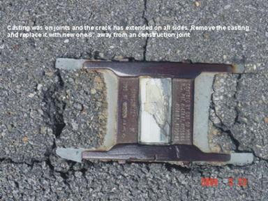
Remedial Action:
Remove and reinstall the RPM
casting at a new location.
New RPM location shall not
exceed 25 percent of the specified RPM spacing.
If necessary to relocate the
RPM to a distance greater than 25 percent of the RPM spacing, do not install
the affected RPM.
Fill the old cavity on the
roadway surface with epoxy or asphalt concrete from where the RPM casting is
removed.
Raised Pavement Markers Removed
Remove raised pavement markers in concurrence with the
maintenance of traffic phases so that their existence or removal will not
conflict with the temporary pavement markings or snow and ice removal.
Remove all standing water and fill with asphalt
concrete. By the end of the next workday, depressions will be caused by
removing the castings. Compact the
asphalt concrete flush with the pavement.
Documentation
Requirements - 621 Raised Pavement Markers
1. Verify castings to be used are on the Qualified
Products List (QPL) before permitting
installation.
2. Verify the epoxy to be used to install the casting is
on the Qualified
Products List (QPL).
3. Make sure that the keels of the casting are placed
into the slots so that the tips of the RPM snowplow deflecting surfaces on the
keels, which are below the pavement surface, and all four lugs/tabs on the
keels of the casting, are in contact with the pavement.
4. Check before placement of the epoxy, the saw cut is
clean of all loose material and dry. Saw cut should have 1/8-inch clearance on
all sides of the casting.
5. Verify ambient air temperatures are at least 40 °F and
the pavement is dry.
6. Check epoxy is an A+B
mixture, thoroughly mixed (grey color), and in accordance with manufacturer’s
recommendations.
7. Check that sufficient epoxy is in and between the slots
to ensure that all voids beneath and around the casting are filled.
8. Placement of RPM castings shall be 6 inches from any
construction joint (lateral or longitudinal).
9. Location and stations are per Standard
Construction Drawings TC 65.10 and TC 65.11.
10. Check quantity totals for payment.
11. Document on CA-D-3B.
12. Verify RPM reflectors to be used are on the Qualified
Products List (QPL) before permitting
installation.
13. Verify that all dirt, dust, oil, grease, rust,
moisture, parts of damaged reflectors, or any foreign matter is removed that
impairs adhesion of the reflector to the casting.
14. Verify reflector area of the castings shall be
sandblasted to 80 percent bare metal.
15. Verify the application of adhesive is in a single
bead, sufficient to squeeze out on all sides of the reflector when pressure is
applied, to seat the reflector and seal out moisture.
16. Document on CA-D-3B.