640 Pavement Markings
641 Pavement Markings – General
This information is intended
to serve as a guide for construction personnel where the Contractor furnishes
and installs traffic control marking devices. This information may also be useful
for maintenance personnel performing the same functions.
As per 641.06, the Contractor shall establish
reference points to ensure proper placement of restored markings on projects
where resurfacing or other operations will result in obliteration of the
existing pavement markings.
Please refer to the Traffic
Engineering Manual for a complete list of forms and supplementary
information. Updates are available on the following ODOT website:
Pavement Marking Materials (641.02)
Pavement marking materials
used on the construction projects shall be as listed on the Approved
List.
The Approved List for
pavement marking materials is maintained by the Office of Material Management (OMM) and is available on the website.
http://www.dot.state.oh.us/Divisions/ConstructionMgt/Materials/Pages/PAVEMENT-MARKING-MATERIALS.aspx
The appropriate type of glass
beads shall be applied according to C&MS 740.09 for different types of pavement marking
materials.
Application of Pavement Marking Materials (641.03)
Pavement marking materials
shall be applied according to C&MS Items 640
and 740.
Data Logging System (DLS)
(641.04)
The Data logger System can be
verified in the field by using the following method:
DLS Verification
Testing
This section provides
information on the Data Logger System (DLS) for
long-line striping trucks, the reports generated by DLS,
and how to use the reports to verify compliance with specifications.
DLS Requirements
The requirements for DLS are contained in C&MS Section 641.04.
According to Item 641.04, long-line striping equipment
for traffic paint, polyester, epoxy, and work zone markings (Item 642) shall be equipped with a computerized
Data Logger System (DLS) to document long-line
markings as follows:
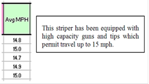
1. Measure and record application vehicle speed to nearest
0.1 mph.
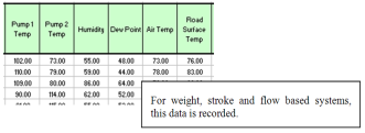
2. Measure and record weight and/or volume amount of
material used by color.
3. Measure and record weight of glass beads.
4. Measure and record pavement surface temperature.
5. Measure and record air temperature.
6. Measure and record dew point.
7. Measure and record humidity.
8. Calculate and record average material application
rates and film thickness over the section painted.
9. ODOT provides
standard DLS spreadsheets which prescribe the
correct DLS report format and content.
DLS are not required for any markings applied by hand,
with push carts, for channelizing lines, or Class II work zone markings.
When the Striping Truck Arrives on the
Project
·
Each district
should establish one individual as District DLS
Contact to receive DLS Reports for all striping
activities. Check with the District Construction Office for the email address
of the District DLS Contact to provide to the
Contractor.
·
Make sure every
vehicle in the striping train has the correct maintenance of traffic equipment
and signs. See SCD
MT-99.20 and plan notes.
·
Check the
driver’s door or the door of the DLS unit to confirm
the presence of the DLS calibration sticker. It
should be signed and carry a date no more than one-year-old. Every DLS must be calibrated once every year.
·
Make sure that
there are adequate TE-24s to cover all materials needed for the job.
·
Make arrangements
with the Contractor’s crew foreman to get DLS Short
Reports for each day’s work. DLS Short Reports are to
be provided to ODOT the next working day or, when requested by ODOT personnel,
any time route sections are completed on any given day. ODOT should receive a
report from the Contractor for each day worked. The DLS
specification requires the Contractor to furnish ODOT with a paper copy of the DLS Short Report which should be retained to compare to the
electronic file that will be received later.
·
The Data Logger
System shall be verified by field personnel.
Field personnel shall randomly verify the components of the DLS. The purpose of
this is to verify that the striping truck places the material shown on the DLS printout. Field
personnel should try to verify the DLS of every paint
contractor at least once per construction season. If field personnel believe that the DLS printouts are not accurate, then more field checks can
be taken.
How to Field Verify the Data Logger System
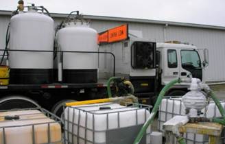
Figure 640.A – Striping
Truck with DLS System

Figure 640.B – Electronic
Control Box
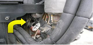
Figure 640.C – Sensors
Sensors such as temperature sensors,
located at appropriate locations on the striping truck, provide temperature
data.
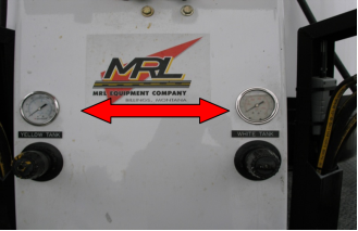
Figure 640.D – Gauges
Gauges provide data and help monitor the temperatures of striping material
in the tanks.
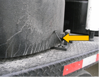
Figure 640.E – Glass Bead
Tank Load Cells
Glass bead tanks are mounted on load cells. Load cells are the basis of bead weight
calculations.
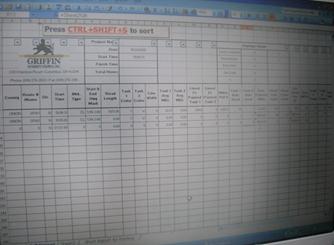
Figure 640.F – DLS Electronic Data Sheet
1. DLS data is automatically recorded and stored
electronically.
2. DLS data includes:
a. Sensor data.
b. Distance data.
c. Ambient conditions.
d. Material quantities.
3. Verification test results will be compared to the
Contractor’s electronic sheet data.
Calibration Sticker
Check
Check for the presence of the
annual calibration sticker.
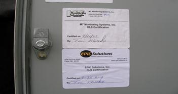
Figure 640.G – Calibration
Sticker
Evidence of the annual
calibration shall be a signed and affixed sticker to the inside of the driver’s
door of each striping truck.
Yearly Calibration
1. As per C&MS 641.04,
each DLS shall have an annual calibration.
2. Items to be calibrated include:
a. All mechanical and electrical components.
b. Software.
c. Function and output.
3. Calibration will be confirmed by the manufacturer.
The Plate Test
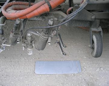
Figure 640.H – The Plate
Test
1. Place an aluminum plate, approximately 24 inches by 8
inches under the paint gun of the striping truck. Aluminum plates are supplied
through the Office
of Materials Management (OMM), Chemical Section.
2. Allow the striping truck to stripe over the plate in
order to get a stripe of the desired thickness on the plate.
3. Send the striped plate to the OMM,
Chemical Section for film thickness testing.
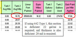
After converting dry film thickness to wet film thickness, the
difference obtained from the plate should be no more than 5 percent from the DLS reading.
4. Send the Contractor’s DLS
average mils applied data as comparison for the film thickness testing results.
See picture below.
5. Note: Be careful not to damage the paint stripe on the
plate.
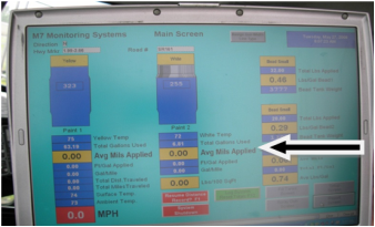
Figure 640.I – Average Mils
Applied
The Bead Weight Test
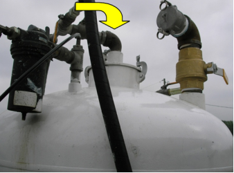
Figure 640.J – The Bead
Weight Test
1. Check and record the bead weight on the DLS electronic data sheet W1.
2. Obtain an object of known weight. Must be a minimum of
20 pounds (e.g., a 50 pound bag of glass beads).
3. Place the weight on top of the bead tank. Keep the
weight in position on top of the tank and check and record the new weight, W2,
on the DLS electronic data sheet.
Subtract W1 from W2 to get
the known weight of the object used.
W2 – W1 = weight of the
object of known weight used.
Correct test results confirm
the proper operation of the bead tank load cells as well as the accuracy of the
data on the spreadsheet. The difference
should be no more than 5 percent.
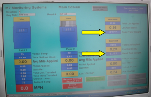
Figure 640.K – The Bead
Weight Test
The Infrared
Thermometer Test
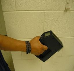
Figure 640.L – The Infrared
Thermometer Test
Use a hand-held Infrared Thermometer to measure road surface temperature, air temperature, and/or striping material
temperature.
1. To operate the infrared thermometer, follow the manufacturer’s
operating procedures.
2. Compare temperature readings to the data on the
appropriate DLS electronic screen.
3. Temperature readings on the DLS
screen should be within ±5 percent of the thermometer readings.
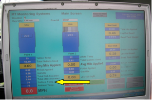
Figure 640.M – The Infrared
Thermometer Test
The
Humidity Test
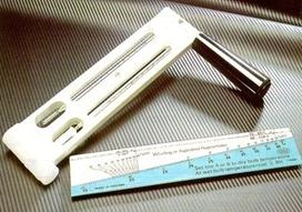
Figure 640.N – The Humidity
Test
1.
Measure the
ambient humidity with the use of a sling hydrometer.
2.
To operate the
sling hydrometer, follow the manufacturer’s operating procedures.
3.
Compare humidity
readings to the data on the appropriate DLS
electronic screen.
4.
Humidity readings
on the DLS screen should be within ±5 percent of the
hydrometer readings.
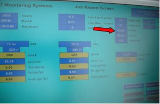
Figure 640.O – The Humidity
Test
The Distance Traveled Test

Figure 640.P – The Distance
Traveled Test
1. Testing the distance traveled data on the DLS electronic data screen can be done using a distance
wheel like the one shown in the picture.
2. To operate the distance wheel, follow the
manufacturer’s operating procedures.
3. Compare distance readings to the data on the
appropriate DLS electronic screen.
4. Distance readings on the DLS
screen should be within ±5 percent of the distance wheel readings.
5. DLS distance data can also be checked using mile markers
and an accurate odometer.
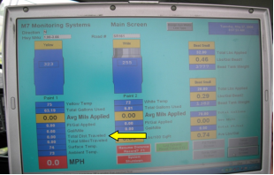
Figure 640.Q – The Distance
Traveled Test
Summary
1. The specified annual calibration of the data logger
system is the primary check of the operation of the systems.
2. The tests described above are meant to be done in a
random fashion to:
a. Verify proper operation after calibration.
b. Verify correct millages are
applied.
c. Determine if the system is the cause of suspicious
developments in the field application of striping material.
3. One or all of the tests may be used to check the DLS operation.
What to Do When the DLS Fails
DLS Reports
Delivery of DLS Reports
Each district should
establish a District DLS Contact person who will
receive email copies of the DLS Reports and provide
that person’s name and email address at the preconstruction meeting.
The paper copy of the DLS Short Report covering all route sections completed each
day must be provided to ODOT personnel the next working day. A paper copy of
the DLS Short Report may be requested from the
Contractor by ODOT personnel at any time during striping operations for those
route sections completed so far that day. The paper copy of the DLS Short Report should be retained by the project and
compared to the DLS Full Report for the same route
sections, which will be provided to ODOT personnel by the Contractor at a later
time, as described below.
DLS Full Reports contain all project, application, and
environmental data and can be provided to ODOT by any one of the following
methods, which should be agreed upon at the preconstruction meeting:
·
Hand delivery of
paper report.
·
Fax delivery of
paper report.
·
E-mail
an electronic version of the Excel
spreadsheet file.
Within two weeks of the application
date of the markings which require documentation with the DLS,
the Contractor is required to furnish the District DLS
Contact with an electronic version of the Excel spreadsheet file of the DLS Report in ODOT standard DLS
Report format by e-mail at the e-mail address provided at the preconstruction
meeting. Note: This file will contain both the DLS
Full Report and the DLS Short Report on separate
sheet tabs.
At the end of the project,
the Contractor is required to furnish the District DLS
Contact with all DLS Excel spreadsheet files in ODOT
standard DLS Report format. Note: This file will
contain both the DLS Full Report and the DLS Short Report on separate sheet tabs. The Engineer
shall forward the final electronic copy containing the DLS
Long report and the DLS short report to the following
address:
DLS.Report@dot.state.oh.us
DLS Report Security
ODOT has established a method
to monitor accuracy of DLS Reports. This method is
based on comparison of the paper copy DLS Short
Reports for daily production to the DLS Full Report for the same day. Note: The DLS Short Report does not contain all project or
environmental information, but does contain all information necessary to
monitor correct application rates and speed.
The Contractor is required to
provide ODOT personnel with a paper copy of the DLS
Short Report for each day’s production the next working day. ODOT personnel may
also occasionally request a copy of the DLS Short
Report during the day for those route sections completed thus far that day. On
projects with only partial days of striping work, ODOT personnel should request
the DLS Short Report immediately after the Contractor
finishes the striping operation. Printing of the DLS
Short Report soon after completion of the striping operation will minimize the
opportunity for tampering.
ODOT will keep these paper
reports and compare them to the DLS Full Report that
is received later. Any differences in sections, lengths, quantities, or
application rates between the Short Report and Full Report should be considered
suspect and will be investigated more closely. There should be no valid reason
for any differences between these reports beyond the complete listing of route
sections between partial day and full day reports.
Pay Items
Pay items are plan quantity.
If there is a significant variance between the actual and plan quantities, meet
with the ODOT project personnel to address the issue. Please note that per
C&MS Section 641.12,
Method of Measurement, pavement markings are designed, measured, and paid
“end-to-end,” including gaps, intersections, and other sections of pavement not
normally marked. This provision applies to all types of roadways and lines.
The DLS
is used for two purposes, neither of which is to measure pay item quantities:
1. To monitor environmental conditions and material
application parameters, such as temperatures.
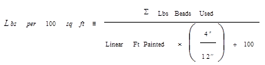
2. To monitor actual application rates of marking
materials and glass beads for purposes of determining deficiencies in
accordance with Section 641.11.
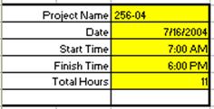
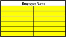
How Data Is Entered
into DLS Reports
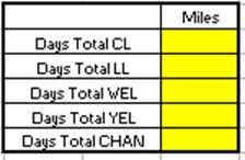
Each report has three
different types of cells which are color-coded:
1. One type contains data which may be manually entered
during striping operations (yellow). Note that this information may also be
entered into the job screens of the DLS console and
come into the Report without additional manual entry.
2. One type contains data which must come directly from
the DLS (green).
3. One type contains values that are calculated by the
spreadsheet (rose) from data provided by the DLS.
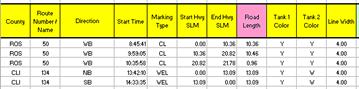
The DLS
Short Report and the DLS Full Report will have one
row for each section painted, by route and by
direction, even if the section length is less than 10 miles. (A route section
is a continuous section of highway without breaks, with the same route number
designation in one direction of travel.) A
new route section is not started at 10 miles if the route and direction stay
the same even when the section length exceeds 10 miles. Whenever material or
beads are loaded, the route section is ended. Start a new route section, for
that route, to complete the route or, if needed, until reloading.
Depending on how the
Contractor sequences work, the route sections will generally match the plan
sub-summary.
How to Read a DLS Report
Check General
Project Information
The mileage values may be entered by crew from their
daily work logs.
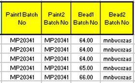
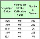
Weight per gallon, per batch,
is entered into the DLS console during job setup for
liquid materials for all DLS types and reported here
as recorded data. Note the weight per gallon may vary per batch.
For stroke-based DLS only, stroke calibration is entered into the DLS console during setup and reported here as recorded
data. The number of strokes is recorded during striping. This information is
used by the DLS to calculate gallons used.
If You Need Further
Assistance
Should it be necessary,
please contact Dan Groh at Central Office Construction, (614) 387-1162 or Maria
Kerestly at the Office of Material Management, (614) 275-1349 for further
assistance.
Construction Inspection during Pavement Marking
Installation
Before the application of
marking material, pavement surface should be clean and dry by using:
1. Power broom.
2. Air jets (guns).
Approve the pre-marking for
long lines and auxiliary markings to ensure proper layout placement.
Center lines shall be “T”
marked to establish no-passing lines.
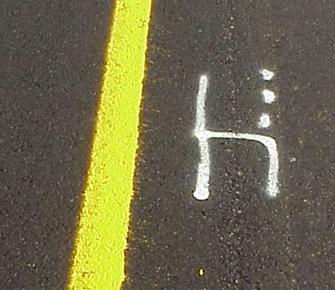
Figure 640.R – Example of Premarking
District shall provide center
line paint logs.
As per Item 641.06,
the Contractor shall establish reference points to ensure proper placement of
restored markings on projects where resurfacing or other operations will result
in obliteration of the existing pavement markings.
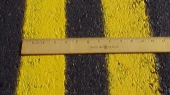
Figure 640.S – Example of
Measurement of Markings
Marking lines shall be
applied to the width specified, ±1/4 inch.
Pavement markings shall be
free of uneven edges, overspray, and other visible defects.
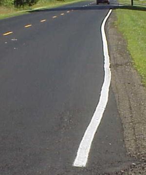
Figure 640.T – Example of
Uneven Edge Line Placement
Pavement marking lines shall
be placed as per SCD TC-73.10 as follows:
1. Edge lines shall be applied 6 inches from the pavement
edge.
2. Lane lines shall be applied 2 inches to left of joint.
3. Center lines shall be applied 2 inches from joint.
Pavement marking lines shall
be straight or smoothly curved true to the alignment of the pavement.
1. If deviation is greater than 3 inches in 100 feet, it
shall be corrected.
Gaps shall be filled that
were not marked as a result of template use for spray-applied auxiliary
markings with marking material after the template is removed.
1. For extruded thermoplastics, gaps may be left.

Figure 640.U – Example of Retroreflectivity Check
Pavement marking lines shall
be sharp, well defined and uniformly retroreflective.
1. To check for retroreflectivity,
put sun over shoulder.
2. If it is not sunny:
a. A well beaded line in the daylight will appear dull.
b. An unbeaded line will be
shiny.
3. If possible, review lines at night for retroreflectivity.