STATE
OF OHIO
DEPARTMENT
OF
TRANSPORTATION
COLUMBUS,
OHIO
CONSTRUCTION
AND MATERIAL
SPECIFICATIONS

JANUARY
1, 2002
An
Equal Opportunity Employer
STATE
OF OHIO
DEPARTMENT
OF
TRANSPORTATION
COLUMBUS,
OHIO
CONSTRUCTION
AND MATERIAL
SPECIFICATIONS
JANUARY
1, 2002
An
Equal Opportunity Employer
Copies of the Construction and Material Specifications may be purchased by contacting:
Ohio
Department of Transportation
Office of
Contracts
P.O. Box 899
Columbus, Ohio
43216‑0899
Telephone (614)
466‑3778, 466‑3200
102 Bidding Requirements and Conditions
103 Award and Execution of Contract
107 Legal Relations and Responsibility to Public
109 Acceptance, Measurement, and Payment
Item 201 Clearing and Grubbing
Item 202 Removal of Structures and Obstructions
Item 203 Roadway Excavation and Embankment
Item 204 Subgrade Compaction and Proof Rolling
Item 206 Lime Stabilized Subgrade
Item 207 Temporary Sediment and Erosion Controls
Item 251 Partial Depth Pavement Repair
Item 252 Full Depth Rigid Pavement Removal and
Flexible Replacement
Item 255 Full Depth Pavement Removal and Rigid
Replacement
Item 256 Bonded Patching of Portland Cement Concrete
Pavement
Item 301 Asphalt Concrete Base
Item 302 Asphalt Concrete Base
Item 305 Portland Cement Concrete Base
Item 306 Cement Treated Free Draining Base
Item 307 Non-Stabilized Drainage Base
Item 308 Asphalt Treated Free Draining Base
Item 321 Cracking and Seating Existing Plain Concrete
Pavement
Item 401 Asphalt Concrete Pavements—General
Item 402 Asphalt Concrete Mixing Plants
Item 403 Asphalt Concrete Quality Control
and Acceptance
Item 409 Sawing and Sealing Asphalt Concrete Pavement
Joints
Item 410 Traffic Compacted Surface
Item 411 Stabilized Crushed Aggregate
Item 422 Chip Seal With Polymer Binder
Item 423 Crack Sealing, Hot Applied
Item 441 Contractor Mix Design and Quality
Control—General
Item 442 Superpave Asphalt Concrete
Item 451 Reinforced Portland Cement Concrete
Pavement
Item 452 Non-Reinforced Portland Cement
Concrete Pavement
Item 502 Structures for Maintaining Traffic
Item 503 Excavation for Structures
Item 504 Sheet Piling Left In Place
Item 505 Pile Driving Equipment Mobilization
Item 511 Concrete for Structures
Item 513 Structural Steel Members
Item 514 Painting of Structural Steel
Item 515 Prestressed Concrete Bridge Members
Item 516 Expansion and Contraction Joints Joint
Sealers
and Bearing Devices
Item 518 Drainage of Structures
Item 519 Patching Concrete Structures
Item 520 Pneumatically Placed Mortar
Item 522 Structural Plate Corrugated Metal Structures
on Footings
Item 601 Slope and Channel Protection
Item 603 Pipe Culverts, Sewers, and Drains
Item 608 Walks, Curb Ramps, and Steps
Item 609 Curbing, Concrete Medians, and Traffic
Islands
Item 610 Cellular Retaining Walls
Item 613 Low Strength Mortar Backfill
Item 615 Roads and Pavements for Maintaining Traffic
Item 617 Reconditioning Shoulders
Item 618 Rumble Strips on Shoulders
Item 621 Raised Pavement Markers (RPM)
Item 623 Construction Layout Stakes
Item 630 Traffic Signs and Sign Supports
Item 631 Sign Lighting and Electrical Signs
Item 632 Traffic Signal Equipment
Item 633 Traffic Signal Controllers
Item 638 Water Mains and Service Branches
Item 641 Pavement Marking—General
Item 643 Polyester Pavement Marking
Item 644 Thermoplastic Pavement Marking
Item 645 Preformed Pavement Marking
Item 646 Epoxy Pavement Marking
Item 647 Heat-Fused Preformed Plastic Pavement
Marking
Item 652 Placing Stockpiled Topsoil
Item 653 Topsoil Furnished and Placed
Item 654 Renovating Existing Soil
Item 657 Riprap for Tree Protection
Item 661 Planting Trees, Shrubs, and Vines
Item 666 Pruning Existing Trees
Item 671 Temporary Erosion Control Mats
707 Steel, Aluminum, and Plastic Pipe
711 Structural Steel and Structure Incidentals
721 Raised Pavement Marker Materials
725 Lighting and Electrical Materials
730 Traffic Sign and Support Material
731 Sign Lighting and Electrical Signs Material
733 Traffic Signal Controller Material
748 Water Main and Service Branch Material
101.01 General. These Construction and Material Specifications are written to the Bidder before award of the Contract and to the Contractor after award of the Contract. The sentences that direct the Contractor to perform Work are written as commands. For example, a requirement to provide cold-weather protection would be expressed as, “Provide cold-weather protection for concrete,” rather than “The Contractor shall provide cold-weather protection for concrete.” In the imperative mood, the subject “the Bidder” or “the Contractor” is understood.
All requirements to be performed by others have been written in the active voice. Sentences written in the active voice identify the party responsible for performing the action. For example, “The Engineer will determine the density of the compacted material.” Certain requirements of the Contractor may also be written in the active voice, rather than the active voice and imperative mood, if the sentence includes requirements for others in addition to the Contractor. For example, “After the Contractor provides initial written notice, the Engineer will revise the Contract as specified in 104.02.”
Sentences that define terms, describe a product or desired result, or describe a condition that may exist are written in indicative mood. These types of sentences use verbs requiring no action. For example, “The characteristics of the soils actually encountered in the subgrade may affect the quality of the cement and depth of treatment necessary.”
101.02 Abbreviations. The following abbreviations, when used in the Contract Documents, represent the full text shown.
AAN American Association of Nurserymen
AASHTO American Association of State Highway and Transportation Officials
ACI American Concrete Institute
AISC American Institute of Steel Construction
AISI American Iron and Steel Institute
ANSI American National Standards Institute
AREA American Railway Engineering Association
ASCE American Society of Civil Engineers
ASME American Society of Mechanical Engineers
ASTM American Society of Testing and Materials
AWG American Wire Gauge
AWPA American Wood Preservers’ Association
AWS American Welding Society
AWWA American Water Works Association
CMS Construction and Material Specifications of the Ohio Department of Transportation
DCE District Construction Engineer
DDD District Deputy Director
DET District Engineer of Tests
DNR Department of Natural Resources
EEI Edison Electric Institute
EPA Environmental Protection Agency
FHWA Federal Highway Administration, Department of Transportation
FSS Federal Specifications and Standards, General Services Administration
IEEE Institute of Electrical and Electronic Engineers
IES Illuminating Engineering Society
IMSA International Municipal Signal Association
IPCEA Insulated Power Cable Engineers Association
ISSA International Slurry Seal Association
ITE Institute of Transportation Engineers
JMF Job Mix Formula
MSDS Material Safety Data Sheets
NCHRP National Cooperative Highway Research Program
NEMA National Electrical Manufacturers Association
NIST National Institute of Standards and Technology
NPDES National Pollutant Discharge Elimination System
OAC Ohio Administrative Code
ODOT Ohio Department of Transportation
OMUTCD Ohio Manual of uniform Traffic Control Devices
ORC Ohio Revised Code
ORDC Ohio Rail Development Commission
OSHA Occupational Safety and Health Administration
PCC Portland Cement Concrete
REA Rural Electrification Administration
SSPC Steel Structures Painting Council
UL Underwriters’ Laboratories, Inc.
101.03 Definitions. The following terms or pronouns, when used in the Contract Documents, are defined as follows:
Advertisement. The public announcement, as required by law, inviting Bids for Work to be performed or materials to be furnished.
Award. The written acceptance by the Director of a Bid.
Bid. The offer of a Bidder, on the prescribed form properly signed and guaranteed, to perform the Work and to furnish the labor and materials at the prices quoted.
Bidder. An individual, firm, or corporation submitting a Bid for the advertised Work, acting directly or through the duly authorized representative, and qualified as provided in ORC 5525.02 to 5525.09.
Bridge. A structure, including supports, erected over a depression or an obstruction, such as water, a highway, or a railway, and having a track or passageway for carrying traffic or other moving loads and having a length measured along the center of roadway of more than 10 feet (3.048 m) between undercopings of abutments or extreme limits of openings for multiple boxes.
A. Length. The length of a bridge structure is the over‑all length measured along the centerline of the roadway surface.
B. Roadway Width. The clear width measured at right angles to the longitudinal centerline of the bridge between the bottom of curbs or guard timbers or, in the case of multiple heights of curbs, between the bottoms of the lower risers. For curb widths of 1 foot (0.3 m) or less, the roadway width is measured between parapets or railings.
Calendar Day or Day. Every day shown on the calendar.
Certified Test Data. A test report from a manufacturer’s or an independent laboratory approved by the Director listing actual test results of samples tested for compliance with specified Department requirements. The Department will accept certified test data from manufacturers’ laboratories if their products have been used satisfactorily on prior Department contracts and their test data has been confirmed. Include a statement that the test data furnished is representative of the material furnished to a Department project or to a supplier. The report is identified by number or date and identifies the Department project or supplier to which the material is shipped. Submit reports signed by a person having legal authority to act for the manufacturer or independent laboratory.
Change Order. A written order issued by the Director to the Contractor, covering changes in the plans or quantities, or both, within or beyond the scope of the Contract and establishing the basis of payment and time adjustments for the work affected by the changes.
Completion Date. The date, as shown in the Contract Documents, on which the Work contemplated shall be completed.
Contract. The written agreement between the Department and the Contractor setting forth the obligations of the parties, including, but not limited to, the performance of the Work and the basis of payment.
Contract Bond. The approved forms of security, executed by the Contractor and its Sureties, guaranteeing complete execution of the Work as required by the Contract Documents and the payment of all legal debts pertaining to the construction of the Project which security shall comply with and be subject to ORC 5525.16 and 5525.13, and related provisions.
Contract Documents. The Contract Documents include the Invitation for Bids, Addenda, Proposal, contract form and required bonds, Specifications, Supplemental Specifications, Special Provisions, general and detailed plans, Plan notes, standard construction drawings identified in the Plans, notice to contractor, Change Orders, Supplemental Agreements, Extra Work Contracts, and any other document designated by the Department as a Contract Document, all of which constitute one instrument.
Contract Item (Pay Item). A specifically described unit of Work for which a price is provided in the Contract.
Contract Time. The number of workdays or calendar days, including authorized adjustments, allowed for completion of the Project. When a specified Completion Date is shown in the Contract Documents instead of the number of workdays or calendar days, completion of the Project shall occur on or before that date. Specified Completion Date and Calendar Day Contracts shall be completed on or before the day indicated even when that date is a Saturday, Sunday, or holiday.
Contractor. The individual, firm, or corporation contracting with the Department for performance of prescribed Work, acting directly or through a duly authorized representative and qualified under the provisions of ORC 5525.02 to 5525.09 inclusive, and any amendments thereto.
County. The designated county in which the Work specified is to be done.
Culvert. Any structure not classified as a Bridge that provides an opening under the roadway.
Department. The Department of Transportation, State of Ohio.
Director. Administrative head of the Department appointed by the Governor.
Engineer. Duly authorized agent of the Department acting within the scope of its authority for purposes of engineering and administration of the Contract.
Equipment. All machinery and equipment, together with the necessary supplies for upkeep and maintenance, and also tools and apparatus necessary for the proper construction and acceptable completion of the Work.
Extra Work. An item of Work not provided for in the Contract as awarded but found essential to the satisfactory completion of the Contract within its intended scope.
Extra Work Contract. A Contract concerning the performance of Work or furnishing of materials involving Extra Work. Such Extra Work may be performed at agreed prices or on a force account basis as provided in ORC 5525.14.
Fabricator. The individual, firm, or corporation that fabricates structural metals or prestressed concrete members as an agent of the Contractor.
Final Inspector. An Engineer appointed by the DDD who inspects the completed Work and accepts it if it complies with the Contract Documents.
Inspector. The Engineer’s authorized representative assigned to make detailed inspections of Contract performance.
Invitation for Bids. The invitation for Proposals for all Work on which Bids are required. Such Proposal will indicate with reasonable accuracy the quantity and location of the Work to be done or the character and quality of the material to be furnished and the time and place of the opening of Proposals.
Laboratory. The testing laboratories of the Department, including the Office of Materials Management located at 1600 West Broad Street, Columbus, Ohio, and various District testing facilities.
Materials. Any materials or products specified for use in the construction of the Project and its appurtenances.
Plans. The plans, profiles, typical cross-sections, standard construction drawings, working drawings, and supplemental drawings, approved by the Department, or exact reproductions thereof, that show the location, character, dimensions, and details of the Work.
Profile Grade. The trace of a vertical plane intersecting the top surface of the proposed wearing surface, usually along the longitudinal centerline of the roadbed. Profile grade means either elevation or gradient of such trace according to the context.
Project Right-of-Way. That portion of the Right-of-Way between the beginning and end of the Project.
Project. The specific section of the highway together with all appurtenances and Work to be performed thereon under the Contract.
Proposal. The approved form on which the Department requires Bids to be prepared and submitted for the Work.
Proposal Guaranty. The security furnished with a Bid to guarantee that the Bidder will enter into the Contract if its Bid is accepted.
Questionnaire. The specified forms on which the Contractor shall furnish required information as to its ability to perform and finance the Work required under ORC 5525.01.
Reasonably Close Conformity. Reasonably close conformity means compliance with reasonable and customary manufacturing and construction tolerances where working tolerances are not specified. Where working tolerances are specified, reasonably close conformity means compliance with such working tolerances. Without detracting from the complete and absolute discretion of the Engineer to insist upon such tolerances as establishing reasonably close conformity, the Engineer may accept variations beyond such tolerances as reasonably close conformity where they will not materially affect the value or utility of the Work and the interests of the Department.
Registered Engineer. An engineer registered with the Ohio State Board of Registration for Professional Engineers and Surveyors to practice professional engineering in the State of Ohio
Registered Surveyor. A surveyor registered with the Ohio State Board of Registration for Professional Engineers and Surveyors to practice professional surveying in the State of Ohio.
Right‑of‑Way. A general term denoting land, property, or interest therein, usually in a strip, acquired for or devoted to a highway.
Road. A general term denoting a public way for purposes of vehicular travel, including the entire area within the Right‑of‑Way, as defined in ORC 5501.01.
Roadbed. The graded portion of a highway within top and side slopes, prepared as a foundation for the pavement structure and shoulder.
Roadside. The areas between the outside edges of the shoulders and the Right‑of‑Way boundaries. Unpaved median areas between inside shoulders of divided highways and infield areas of interchanges are included.
Roadside Development. Those items necessary to the highway that provide for the preservation of landscape materials and features; the rehabilitation and protection against erosion of all areas disturbed by construction through seeding, sodding, mulching, and the placing of other ground covers; such suitable planting; and other improvements as may increase the effectiveness and enhance the appearance of the highway.
Roadway. The portion of a highway within limits of construction.
Shoulder. The portion of the roadway contiguous to the traveled way for accommodation of stopped vehicles, for emergency use, and for lateral support of base and surface courses.
Sidewalk. That portion of the roadway primarily constructed for the use of pedestrians.
Signatures on Contract Documents. All signatures on Contract Documents must meet the requirements of 102.06.
Special Provisions. Additions and revisions to the standard and Supplemental Specifications covering conditions peculiar to an individual Project.
Specifications. The directions, provisions, and requirements contained herein as supplemented by the Supplemental Specifications and Special Provisions.
State. The State of Ohio acting through its authorized representative.
Street. A general term denoting a public way for purpose of vehicular travel, including the entire area within the Right‑of‑Way.
Structures. Bridges, culverts, catch basins, drop inlets, retaining walls, cribbing, manholes, endwalls, buildings, sewers, service pipes, underdrains, foundation drains, and other features that may be encountered in the Work and not otherwise classed herein.
Subcontractor. An individual, firm, or corporation to whom the Contractor sublets part of the Contract to be performed on the job site, who prior to such undertaking receives the written consent of the Director, and who is qualified under ORC 5525.02 through 5525.09 inclusive.
Subgrade. The portion of a Roadbed upon which the pavement structure and shoulders are constructed.
Substructure. All of that part of the structure below the bearings of simple and continuous spans, skewbacks of arches, and tops of footings of rigid frames, together with backwalls and wings.
Superintendent. The Contractor’s authorized representative in responsible charge of the Work.
Superstructure. The entire structure except the Substructure.
Supplement. A list of requirements for fabrication plants, methods of test, or other miscellaneous requirements that are maintained on file in the Office of the Director.
Supplemental Agreement. A written agreement executed by the Contractor and by the Director covering necessary alterations.
Supplemental Specifications. Detailed specifications supplemental to or superseding these Specifications.
Surety. The corporation, partnership, or individual, other than the Contractor, executing a bond furnished by the Contractor.
Titles (or Headings). The titles or headings of the sections and subsections herein are intended for convenience of reference and shall not be considered as having any bearing on their interpretation.
Waters of the united States. Waters that are under the jurisdiction of the Corps of Engineers under the Clean Water Act as defined by 33 CFR Ch. II Part 328, which as applied to Ohio means: the Ohio River and Lake Erie and any other river, stream, creek, lake, pond, or wetland that drains directly or indirectly into the Ohio River or Lake Erie.
Work. The furnishing of all labor, materials, equipment, tools, transportation, supplies, and other incidentals and performance of all tasks necessary for the successful completion of the Project or specific part of the Project, as described by the Contract Documents.
Workday. A calendar day that the Contractor normally works.
Working Drawings. Stress sheets, shop drawings, erection plans, falsework plans, frame work plans, cofferdam plans, bending diagrams for reinforcing steel, or any other supplementary plans or similar data that the Contractor is required to submit for acceptance.
101.04 Interpretations. In order to avoid cumbersome and confusing repetition of expressions in these Specifications, it is provided that whenever anything is, or is to be, done, if, as, or, when, or where “contemplated, required, determined, directed, specified, authorized, ordered, given, designated, indicated, considered necessary, deemed necessary, permitted, reserved, suspended, established, approval, approved, disapproved, acceptable, unacceptable, suitable, accepted, satisfactory, unsatisfactory, sufficient, insufficient, rejected, or condemned,” it shall be understood as if the expression were followed by the words “by the Engineer” or “to the Engineer.”
102 BIDDING REQUIREMENTS AND CONDITIONS
102.01 Prequalification of Bidders. A Bidder must be prequalified by the Department according to ORC Chapter 5525 and the rules and regulations governing prequalification in order to submit a Bid. Upon request, the Department will provide a prequalification application, applicable rules and regulations, and other relevant information. For prospective Bidders that are not yet prequalified, furnish the Department with a properly completed prequalification application at least 30 days before the date specified for the receipt of Bids. The prequalification certificate is the Bidder’s license to Bid and perform construction for the Department.
For foreign Contractors, refer to ORC 5525.18 and Ohio Administrative Rule 5501:2-3-07.
102.02 Contents of Bidding Documents. Use the Proposal to prepare and submit Bids for the Work. Upon request, the Department will provide Bidding Documents that include or reference the following:
A. Location and description of the Project.
B. Estimate of quantities and description of the Work.
C. Time to complete the Work.
D. Amount of the Proposal Guaranty.
E. Department’s deadline for receiving a completed Bid.
F. Schedule of contract items.
G. Standard Specifications, Special Provisions, Supplemental Specifications, and the Plans.
H. Proposal.
102.03 Issuance of Proposals.
A. General. Upon request, the Department will provide applicable rates and other relevant information for obtaining bidding information and submitting a Bid.
B. Department Will Not Issue. The Department may refuse to sell or issue Bidding Documents to a prospective Bidder for any of the following reasons:
1. The prospective Bidder owes the Department for previously issued plans.
2. The prospective Bidder has defaulted on previous contracts.
3. The prospective Bidder is debarred from bidding on and receiving Department contracts.
4. The prospective Bidder is currently in the debarment process.
102.04 Interpretation of Quantities in Proposal. The quantities in the Bidding Documents are approximate and the Department uses them for the comparison of Bids only.
The Department will only pay the Contractor for the actual quantities of Work performed and accepted according to the Contract Documents. The Department may increase, decrease, or omit the scheduled quantities of Work as provided in 109.04 without invalidating the Bid prices.
102.05 Examination of Bidding Documents and Site of Work. Carefully examine the Bidding Documents and perform a reasonable site investigation before submitting a Bid. Submitting a Bid is an affirmative statement that the Bidder has investigated the Project site and is satisfied as to the character, quality, quantities, and the conditions to be encountered in performing the Work. A reasonable site investigation includes investigating the Project site, borrow sites, hauling routes, and all other locations related to the performance of the Work.
When available, the Department will include in the Contract Documents or provide for the Bidder’s review at the Department’s District or other offices, one or more of the following:
A. Record drawings.
B. Available information relative to subsurface exploration, borings, soundings, water levels, elevations, or profiles.
C. The results of other preliminary investigations.
A reasonable site investigation includes a review of these documents.
102.06 Preparation of Bids. Prepare a Bid according to this subsection and the requirements found in the Bidding Documents. Include a completed computerized Proposal produced and printed from software specified in the Bidding Documents rather than completing it by handwriting, typing, or using unauthorized computer-generated forms.
Provide a unit price for each item listed on the Proposal. Calculate and place the products for the respective unit prices and quantities in the “Bid Amount” column. For a lump sum item, place the same price in the “unit Price” column and in the “Bid Amount” column pertaining to that item. Indicate the total Bid amount by adding the values entered in the “Bid Amount” column for the listed items. Include a diskette containing the computerized Proposal.
If a unit price or lump sum price already entered on the Proposal needs to be altered, cross out the entered unit price or lump sum price with ink, enter the new price above or below, and initial it in ink.
Properly execute the Proposal. Place the required signatures, in ink, in the space provided on the Proposal as indicated below:
ENTITY SUBMITTING PROPOSAL
REQUIRED SIGNATURE
|
Individual |
The individual or a duly authorized agent. |
|
Partnership |
A partner or a duly authorized agent. |
|
Joint Venture |
A member or a duly authorized agent of at least one of the joint venture firms. |
|
Corporation |
An authorized officer or duly authorized agent of the corporation. Also, show the name of the state chartering the corporation and affix the corporate seal. |
|
Limited Liability Company |
A manager, a member, or a duly authorized agent. |
102.07 Duty to Notify of Errors in Contract Documents. Notify the Department of errors and omissions in the Bidding Documents. The Contractor’s duty to disclose errors and omissions is not only a bidding requirement but is also a legal requirement that cannot be ignored. Notify the Office of Construction Administration or any other office designated by the Department for receipt of bidding questions and providing information to the Bidder. The Office of Construction Administration or any other designated office will determine the manner in which the said questions are answered or information is distributed.
102.08 Unbalanced Bidding. Bid all items correctly and price each quantity as indicated in the Bidding Documents. The Department will reject a Mathematically Unbalanced Bid if the Bid is also Materially Unbalanced. A Mathematically Unbalanced Bid is a Bid containing lump sum or unit price items that do not include reasonable labor, equipment, and material costs plus a reasonable proportionate share of the Bidder’s overhead costs, other indirect costs, and anticipated profit. A Bid is Materially Unbalanced when the Department determines that an award to the Bidder submitting a Mathematically Unbalanced Bid will not result in the lowest ultimate cost to the Department.
102.09 Proposal Guaranty. The Department will reject a Bid submitted without a Proposal Guaranty in the amount designated and payable to the Director. Submit the required Proposal Guaranty in one of the following forms:
A. Properly executed project Bid bond submitted on the Department’s form.
B. Properly executed annual Bid bond submitted on the Department’s form.
C. Certified check drawn on the account of the Bidder submitting the Bid.
D. Cashier’s check.
When submitting a Bid bond, ensure that the Surety is licensed to do business in the State.
If the Department invites alternate Bids and the Bidder elects to Bid more than one alternate, the Bidder may submit one Proposal Guaranty in the amount required for a single alternate. The Proposal Guaranty covers each individual Bid.
If the Department invites combined Bids and the Bidder elects to Bid only on one package, then the Bidder must submit only one Proposal Guaranty. If the Bidder bids on the combined Bid package, the Bidder must submit a Proposal Guaranty in the amount required for the combined Bid. The combined Proposal Guaranty covers each individual Bid.
102.10 Delivery of Bid. Place each completed Proposal and the Proposal Guaranty in a sealed envelope furnished by the Department. On each envelope, indicate the Proposal number and the name of the Bidder. For mailed submittals, mark the sealed envelope as indicated above and enclose it in an additional envelope. The Department will accept Bids at the place, until the time and date designated in the Notice to Bidders. The Department will return Bids received after the designated time to the Bidders unopened.
102.11 Withdrawal of Bids. Provide a written request to withdraw a Bid already filed with the Department. Submit the withdrawal request before the deadline set for receiving Bids. The Bidder named on a withdrawn Bid cannot subsequently submit another Bid on that Contract unless the Department issues a new Invitation for Bids.
After Bids are opened, ORC 5525.01 requires that a Bidder identify a mistake in its Bid within 48 hours of the Bid opening.
102.12 Combination Proposals. The Department may elect to issue Bid Documents for projects in combination or separately, so that Bids may be submitted either on the combination or on separate units of the combination. The Department reserves the right to make awards on combination Bids or separate Bids to the best advantage of the Department. The Department will not consider combination Bids, other than those it specifically identifies in the Bid Documents. The Department will write separate Contracts for each individual Project included in the combination.
102.13 Public Opening of Bids. The Department will publicly open Bids at the time and place indicated in the notice to Contractors. The Department will read the total Bid amount for each Bid.
Bidders or their authorized agent and other interested persons are invited to the opening.
The Department may postpone the receipt of Bid time or the opening of Bids time. If the Department changes the hour or the date of the receipt of Bids or the opening of Bids, it will issue an addendum or public notice to notify prospective Bidders.
102.14 Disqualification of Bidders. The Department will declare a Bid non-responsive and ineligible for award when any of the following occur:
A. The Bidder lacks sufficient prequalification work types or dollars to be eligible for award.
B. The Bidder fails to furnish the required Proposal Guaranty in the proper form and amount.
C. The Bid contains unauthorized alterations or omissions.
D. The Bid contains conditions or qualifications not provided for in the Bidding Documents.
E. The Proposal is not prepared as specified.
F. A single entity, under the same name or different names, or affiliated entities submits more than one Bid for the same Project.
G. The Bidder fails to submit a unit price for each contract item listed, except for lump sum items where the Bidder may show a price in the “Bid Amount” column for that item.
H. The Bidder fails to submit a lump sum price where required.
I. The Bidder fails to submit a complete EBS-generated Proposal and diskette.
J. The Bidder is debarred from submitting Bids.
K. The Bidder has defaulted or has had a Contract terminated for cause by the Department and has either agreed not to Bid or has had debarment proceedings initiated against the Bidder’s company and its key personnel.
L. The Bidder submits its Bid or Proposal Guaranty on forms other than those provided by the Department.
M. The Bidder fails to submit a properly completed supplemental questionnaire inclusive of signatures and notarization.
N. The Bidder submits a Materially Unbalanced Bid as defined by 102.08.
O. The Bidder fails to acknowledge addenda.
P. The Department finds evidence of collusion.
Q. Any other omission, error, or act that, in the judgment of the Department, renders the Bidder’s bid non-responsive.
102.15 Material Guaranty. Before any Contract is awarded, the Department may require the Bidder to furnish a complete statement of the origin, composition, and manufacture of any or all Materials to be used in the construction of the Work together with samples. The Department may test the samples as specified in these Specifications to determine their quality and fitness for the Work.
103 AWARD AND EXECUTION OF CONTRACT
103.01 Consideration of Proposals. After opening and reading the Bids, the Department will compare the Bidders’ proposed prices. The proposed price is the summation of the products of the estimated quantities shown in the Proposal and the unit Bid prices. If the amount shown for the proposed product differs from the actual product of the unit Bid price and the estimated quantity, then the actual product will govern.
The Department may reject any or all Bids, waive technicalities, or advertise for new Bids without liability to the Department.
103.02 Award of Contract. The Department will award a Contract or reject Bids within 10 days after Bid opening. The Department will mail a letter to the address on the Bid notifying the successful Bidder of Bid acceptance and Contract award. The Department will award to the lowest competent and responsible bidder. The Department will not award a Contract until it completes an investigation of the apparent low Bidder.
If the Department’s estimate for the cost of the improvement is not confidential, the Department will not award a Contract for an amount greater than 5 percent more than the Department’s estimate. If the Department’s estimate is confidential, the Department may award the Contract according to ORC 5525.15.
103.03 Cancellation of Award. The Department may cancel a Contract award at any time before all parties sign the Contract without liability to the Department.
103.04 Return of Proposal Guaranty. Immediately after the opening and checking of Bids, the Department will return all Proposal Guaranties provided in the form of a certified check or cashier’s check, except to the three lowest Bidders. Within 10 days after opening bids, the Department will return the Proposal Guaranties of the two remaining unsuccessful Bidders. After the successful Bidder submits the signed Contract, Contract Bonds, and other Contract Documents, and after the Department signs the Contract, the Department will return the Proposal Guaranty to the successful Bidder. The Department will not return Bid bonds.
103.05 Requirement of Contract Bond. Furnish Contract Bonds within 10 days after receiving notice of award. Furnish Contract Bonds to the Director on the prescribed form, in the amount of the Department’s estimate, and according to ORC 5525.16.
103.06 Execution of Contract. Sign and return the Contract, along with the certificate of compliance, Contract Bonds, and other required Contract Documents, within 10 days after notice of award. The State does not consider a proposal binding until the Director signs the Contract. If the Director does not sign the Contract within 20 days after receiving the successful Bidder’s signed Contract, certificates, Contract Bonds, and other Contract Documents, the successful Bidder may withdraw the Bid without prejudice.
103.07 Failure to Execute Contract. If the successful Bidder fails to sign the Contract and furnish the Contract Bonds, the Department will have just cause to cancel the award. The successful Bidder shall forfeit the Proposal Guaranty to the Department, not as a penalty, but as liquidated damages. The Department may award the Contract to the next lowest responsive Bidder, readvertise the Work, or take any other action decided by the Director.
104.01 Intent of the Contract Documents. The intent of the Contract Documents is to provide for the construction and completion of the Work. Perform the Work according to the Contract Documents.
104.02 Revisions to the Contract Documents.
A. General. The Department reserves the right to revise the Contract Documents at any time. Such revisions do not invalidate the Contract or release the Surety, and the Contractor agrees to perform the Work as revised.
The provisions of this section are subject to the limitation of ORC 5525.14.
B. Differing Site Conditions. During the progress of the Work, if subsurface or latent physical conditions are encountered at the site differing materially from those indicated in the Contract Documents or if unknown physical conditions of an unusual nature, differing materially from those ordinarily encountered and generally recognized as inherent in the Work provided for in the Contract Documents, are encountered at the site, notify the Engineer as specified in 104.02.G of the specific differing conditions before they are disturbed or the affected Work is performed.
Upon notification, the Engineer will investigate the conditions and if it is determined that the conditions materially differ and cause an increase or decrease in the cost or time required for the performance of any Work under the Contract, the Department will make an adjustment and modify the Contract as specified in 108.06 and 109.05. The Engineer will notify the Contractor of the determination whether or not an adjustment of the Contract is warranted.
C. Suspension of Work. If the performance of all or any portion of the Work is suspended or delayed by the Engineer in writing for an unreasonable period of time (not originally anticipated, customary, or inherent to the construction industry) and the Contractor believes that additional compensation or time is due as a result of such suspension or delay, notify the Engineer as specified in 104.02.G.
Upon receipt of notice, the Engineer will evaluate the Contractor’s request. If the Engineer agrees that the cost or time required for the performance of the Work has increased as a result of such suspension and the suspension was caused by conditions beyond the control of and not the fault of the Contractor, its suppliers, or subcontractors at any approved tier, and not caused by weather, the Engineer will make an equitable adjustment (excluding profit) and modify the contract as specified in 108.06 and 109.05. The Engineer will notify the Contractor of its determination whether or not an adjustment to the Contract Documents is warranted. Failure of the Engineer to suspend or delay the Work in writing does not bar the Contractor from receiving a time extension or added compensation according to 108.06 or 109.05.
The Department will not make an adjustment under this subsection in the event that performance is suspended or delayed by any other cause, or for which an adjustment is provided or excluded under any other term or condition of this Contract.
D. Significant Changes in Character of the Work. The Engineer may alter the Work as necessary to complete the Project. The Engineer will make appropriate adjustments according to 108.06 and 109.05, if such alterations significantly change the character of the Work.
If the alterations or changes in quantities significantly change the character of the Work under the Contract, whether such alterations or changes are in themselves significant changes to the character of the Work or by affecting other Work cause such other Work to become significantly different in character, an adjustment, excluding anticipated profit, will be made to the Contract. Before performing significantly changed Work, reach agreement with the Department concerning the basis for the adjustment. If the Contractor disagrees as to whether an alteration constitutes a significant change, use the notification procedures specified in 104.02.G.
The term “significant change” is defined as the follows:
1. when the character of the Work as altered differs materially in kind or nature from that involved or included in the original proposed construction; or
2. when the product of the quantity in excess of the estimated quantity of a contract item and the unit price exceeds the limits set forth in Table 104.02-1. If the increase does not exceed the limits set forth in Table 104.02-1, then the Department will pay for the increased Work at the Contract Price.
|
Table 104.02-1 |
|
|
Contract Price |
Contract Limits |
|
Up to $500,000 |
$25,000 |
|
$500,001 to $2,000,000 |
5% of Total Contract Price |
|
Over $2,000,000 |
$100,000 |
If the decrease in quantity of any unit price Contract Item exceeds 25 percent of the estimated quantity, and the total of all such adjustments for all Contract Items is more then $400, then after the determination of final quantities according to 109.12.C, the Engineer will adjust the unit prices for the affected Contract item by multiplying the bid unit price by the factor obtained from Table 104.02-2.
|
Table 104.02-2 |
|||
|
% Decrease |
Factor |
% Decrease |
Factor |
|
25 to 28 |
1.02 |
61 |
1.14 |
|
29 to 32 |
1.03 |
62 |
1.15 |
|
33 to 35 |
1.04 |
63 |
1.16 |
|
36 to 38 |
1.05 |
64 |
1.17 |
|
39 to 41 |
1.06 |
65 |
1.18 |
|
42 to 44 |
1.07 |
66 |
1.19 |
|
45 to 47 |
1.08 |
67 |
1.20 |
|
48 to 50 |
1.09 |
68 |
1.21 |
|
51 to 53 |
1.10 |
69 |
1.22 |
|
54 to 56 |
1.11 |
70 |
1.23 |
|
57 to 59 |
1.12 |
71 |
1.24 |
|
60 |
1.13 |
72 and over |
1.25 |
E. Eliminated Items. The Department may partially or completely eliminate contract items.
The Department will make an adjustment to compensate the Contractor for the reasonable cost incurred in preparation to perform the eliminated Work prior to the date of the Engineer’s written order eliminating the Work. The adjustment will be determined according to 109.04 and 109.05. Such payment will not exceed the price of the Contract Item.
F. Extra Work. Perform Extra Work as directed by the Engineer. The Department will pay for Extra Work as specified in 109.05. Time extensions, if warranted, will be determined according to 108.06.
G. Contractor Notification.
1. Contractor Initial Oral Notification. Provide immediate oral notification to the Engineer upon discovering a condition that may require a revision to the Contract Documents. Upon notification, the Engineer will attempt to resolve the identified issue as quickly as possible.
2. Contractor 2-Day Notification. If the Engineer has not resolved the identified issue within 2 workdays after receipt of the oral notification, provide a written notice in accordance with the Dispute Resolution and Administrative Claim Process.
3. No Contract Adjustment Without Notification. The Department will not make the adjustments allowed by 104.02.B, 104.02.C, and 104.02.D if the Contractor did not give notice as specified in 104.02.G. This provision does not apply to adjustments provided in Table 104.02-2.
104.03 Rights in and Use of Materials Found on the Work. Upon obtaining the Engineer’s approval, the Contractor may use material, such as stone, gravel, or sand, found in the plan excavation for another Contract Item. The Department will pay for both the excavation of the material under the corresponding Contract Item and for the placement of the excavated material under the Contract Item(s) for which the excavated material is used. Excavate or remove material only from within the grading limits, as indicated by the slope and grade lines.
Obtain written permission from the Engineer according to 107.11.A.
104.04 Cleaning Up. Maintain the Project in a presentable condition. Remove all rubbish, layout stakes, sediment control devices as directed by the Engineer, excess material, temporary structures, and equipment, including stream channels and banks within the Right-of-Way at drainage structures, and all borrow and waste areas, storage sites, temporary plant sites, haul roads, and other ground occupied by the Contractor in connection with the Work. Establish suitable vegetative cover in these areas by seeding and mulching according to Item 659, except for cultivated fields. Leave the Project site in an acceptable condition as determined by the Engineer. The cost of cleanup is incidental to all contract items. The Department may withhold 10 percent of the Bid amount for the mobilization contract item, if included, until performance under this section is complete. See 624.04.
105.01 Authority of the Engineer. The Engineer will decide questions concerning all of the following:
A. The quality and acceptability of Materials furnished.
B. The quantity of Work performed.
C. The Contractor’s rate of progress.
D. The interpretation of the Contract Documents.
E. Acceptable fulfillment of the Contract.
F. Contractor compensation.
The Engineer may suspend all or part of the Work when the Contractor fails to correct conditions that are unsafe for the workers or the general public, fails to comply with the Contract Documents, or fails to comply with the Engineer’s orders. The Engineer may suspend the Work due to adverse weather conditions, conditions considered adverse to the prosecution of the Work, or other conditions or reasons in the public interest.
105.02 Plans and Working Drawings. The Plans show details of structures, the lines and grades, typical cross-sections of the Roadway, and the location and design of structures. Keep at least one set of Plans at the Project at all times.
When required to control the Work, supplement the Plans with working drawings. Prepare working drawings when required by the Contract Documents and after verifying applicable field and plan elevations, dimensions, and geometries. Where Work consists of repairs, extension, or alteration of existing structures, take measurements of existing structures to accurately join old and new Work.
The Department will review working drawing submittals to ensure conformance with the Contract and to provide the Contractor a written response to document the results of its review as follows:
A. “ACCEPTED.” The Department accepts the submittal for construction, fabrication, or manufacture.
B. “ACCEPTED AS NOTED.” The Department accepts the submittal for construction, fabrication, or manufacture, subject to the Contractor’s compliance with all Department comments or corrections to the submittal. If also marked “RESUBMIT,” the Department still accepts the submittal, but requires the Contractor to provide a corrected submittal to the Department.
C. “NOT ACCEPTED.” The Department does not accept the submittal. The submittal does not conform to Contract requirements. Do not begin construction, fabrication, or manufacture of Work included in the submittal. Revise the submittal to comply with Department comments or corrections and Contract requirements and provide the revised submittal to the Department for another review.
The Department’s acceptance will not relieve the Contractor of responsibility to complete the Work according to the Contract. Include the cost of furnishing working drawings in the cost of the Work they cover.
105.03 Conformity with Contract Documents. Perform all Work and furnish all Materials in reasonably close conformity with the lines, grades, cross-sections, dimensions, and material requirements as shown on the Plans and as specified.
If the DCE determines the Work is not in reasonably close conformity with the Contract Documents and determines the Contractor produced reasonably acceptable Work, the DCE may accept the Work based on engineering judgment. The DCE will document the basis of acceptance in a Change Order that provides for an appropriate adjustment to the Contract Price of the accepted Work or Materials.
If the DCE determines the Work is not in reasonably close conformity with the Contract Documents and determines the Work is inferior or unsatisfactory, remove, replace, or otherwise correct the Work at no expense to the Department.
105.04 Coordination of the Contract Documents. The Contract Documents are those defined in 101.01. A requirement appearing in one of these documents is as binding as though it occurs in all. The Engineer will resolve discrepancies using the following order of precedence:
A. Addenda.
B. Proposal and Special Provisions.
C. Plans.
D. Supplemental Specifications.
E. Standard Construction Drawings.
F. Standard Specifications.
Immediately notify the Engineer upon discovering an error or omission in the Contract Documents.
105.05 Cooperation by Contractor. The Department will supply the Contractor with two sets of the Contract Documents, except for the standard construction drawings, which will only be supplied if requested. The Department will provide only one copy of these Specifications.
Provide the constant attention necessary to progress the Work according to the Contract Documents. Cooperate with the Engineer, inspectors, and all other contractors on or adjacent to the Project.
105.06 Superintendent. Provide a Superintendent on the Project at all times, irrespective of the amount of subcontract Work. The Superintendent must be capable of reading and understanding the Contract Documents and experienced in the type of Work being performed. The Superintendent shall receive instructions from the Engineer or the Engineer’s authorized representatives. The Superintendent shall promptly execute the Engineer’s orders or directions and promptly supply the required materials, equipment, tools, labor, and incidentals.
105.07 Cooperation with Utilities. Unless otherwise provided for by the Contract Documents, the Department will direct the utility owners to relocate or adjust water lines, gas lines, wire lines, service connections, water and gas meter boxes, water and gas valve boxes, light standards, cableways, signals, and all other utility appurtenances within the limits of the proposed construction at no cost to the Contractor.
The Contract Documents will indicate various utility items and indicate a time frame or date when the Department expects the owners to complete utility relocation or adjustment. Provide utility owners adjusting facilities during construction with adequate notification of the scheduled Work to prevent conflict with the Contractor’s schedule of operations.
When bidding, consider all permanent and temporary utility appurtenances in present and relocated positions as shown in the Contract Documents.
According to ORC 153.64 and at least 2 Workdays prior to commencing construction operations in an area that may affect underground utilities shown on the Plans, notify the Engineer, the registered utility protection service, and the owners that are not members of the registered utility protection service.
The owner of the underground utility shall, within 48 hours, excluding Saturdays, Sundays, and legal holidays, after notice is received, start staking, marking, or otherwise designating the location, course, ±2 feet (±0.6 m), together with the approximate depth of the underground utilities in the construction area.
If the utility owners fail to relocate or adjust utilities as provided for in the Contract Documents and the Contractor sustains losses that could not have been avoided by the judicious handling of forces, equipment, and plant, or by reasonable revisions to the schedule of operations, then the Engineer will adjust the Contract according to 108.06 and 109.05.
105.08 Cooperation Between Contractors. At any time, the Department may contract for other work on or near the Project.
Separate contractors working within the limits of the Project shall conduct their work without interfering with or hindering the progress or completion of Work being performed by other contractors and shall cooperate with each other as directed by the Engineer.
105.09 Authority and Duties of the Inspector. Inspectors are authorized to inspect the Work and the preparation, fabrication, or manufacture of materials. Inspectors are not authorized to alter or waive requirements of the Contract Documents. Inspectors are authorized to notify the Contractor of Work that does not conform to the Contract; reject materials that do not conform to Specification requirements; and until the issue is decided by the Engineer, suspend portions of the Work if there is a question regarding the Contract Documents, use of unapproved material, or safety. Inspectors are not obligated or authorized to provide direction, superintendence, or guidance to the Contractor, its crew, its subcontractors, or suppliers to accomplish the Work.
105.10 Inspection of Work. The Engineer may inspect materials and the Work. Provide the Engineer or the Engineer’s representative access to the Work, information, and assistance necessary to conduct a complete inspection. Notify the Engineer at least 24 hours prior to all required inspections.
When directed by the Engineer, remove or uncover completed Work to allow inspection. After the Engineer’s inspection, restore the Work according to the requirements of the Contract Documents. If the inspected Work conformed to the requirements of the Contract Documents, the Department will pay for uncovering or removing and restoring the Work as Extra Work according to 109.05. If the inspected Work did not conform to the Contract Documents, the Department will not pay for uncovering or removing and restoring the Work.
The Department’s failure to identify defective Work or material shall not, in any way, prevent later rejection when defective Work or material is discovered, or obligate the Department to grant acceptance under 109.11 or 109.12.
Inspection of Work may include inspection by representatives of other government agencies or railroad corporations that pay a portion of the cost of the Work. This inspection will not make other government agencies or railroad corporations a party to the Contract and will not interfere with the rights of the Contractor or Department.
105.11 Removal of Defective and Unauthorized Work. Work that does not conform to the requirements of the Contract is defective.
Unless the Department accepts defective Work according to 105.03, immediately remove and replace defective Work found to exist prior to the date of the Department’s check for final payment.
Unauthorized Work is Work done contrary to the instructions of the Engineer, beyond the plan lines, or any extra work done without the Department’s permission. The Department will not pay for unauthorized Work. The Engineer may order the Contractor to remove or replace unauthorized Work at no expense to the Department.
If the Contractor fails to comply with the Engineer’s orders under the provisions of this subsection, the DCE may correct or remove and replace defective or unauthorized Work and deduct the costs from the Contract Price.
105.12 Load Restrictions. Comply with all legal load restrictions when hauling materials on public roads.
Operate equipment of a weight or so loaded as to not cause damage to structures, to the roadway, or to other types of construction. Comply with subsection 501.07 for allowed loads on bridges.
Do not use off road vehicles on bases or pavements unless permitted by the DCE in writing.
Do not haul on concrete pavement, base, or structures before the expiration of the curing period.
Do not exceed the legal load limits in this section unless permitted by the Director in writing.
105.13 Haul Roads. Prior to hauling equipment or materials, provide written notification to the Engineer of the specific roads or streets on the haul route. If the haul route includes roads and streets that are not under the jurisdiction and control of the State and the DCE determines that State-controlled roads are not available or practical for a haul route, the Contractor may use local roads and streets that are not restricted by local authorities. If the DCE determines that state-controlled roads are available and practical for a haul route, revise the proposed haul route provided in the original written notification and resubmit to the DCE.
If the Engineer determines that haul route roads were properly used during construction to haul equipment and materials and that the haul route roads were damaged, then the Engineer may order the Contractor to perform immediate and practical repairs to ensure reasonably normal traveling conditions. The Engineer will pay for repairs according to applicable provisions of 109.04 and 109.05.
The Contractor shall not file a claim for delays or other impacts to the Work caused by disputes with the local authorities regarding the use of local roads or streets as haul routes. The Contractor shall save the State harmless for any closures or hauling restrictions outside the Project limits beyond the control of the Department.
105.14 Maintenance During Construction. Maintain the Work during construction and until Final Inspector accepts the work under 109.12, except for portions of the Work accepted under 109.11. The Contractor is responsible for damage done by its equipment.
Maintain the previous courses or subgrade during all construction operations, when placing a course upon other courses of embankment, base, subgrade, concrete or asphalt pavement, or other similar items previously constructed. This maintenance includes, but is not limited to draining, re-compacting, re-grading, or if destroyed, the removal of Work previously accepted by the Department.
Maintain the Work during construction and before acceptance of the Work under 109.12, except for portions of the Work accepted under 109.11. The Department will not provide additional compensation for maintenance work.
105.15 Failure to Maintain Roadway or Structure. If the Contractor, at any time, fails to comply with the provisions of 105.14, the Engineer will immediately notify the Contractor of such noncompliance. If the Contractor fails to remedy unsatisfactory maintenance within 24 hours after receipt of such notice, the Engineer may immediately proceed to maintain the Project, and deduct the entire cost of this maintenance from monies due or to become due the Contractor on the Contract.
105.16 Borrow and Waste Areas The allowed use of Project Right-of-Way and other Department property for borrow and waste is detailed in 104.03 and 107.11.
Whether materials are borrowed or wasted in borrow or waste areas or, if allowed by the Contract Documents, wasted on the Project site, comply with the requirements of this subsection:
Prior to beginning borrow or wasting operations, obtain the Engineer’s written approval of a detailed operation plan that addresses the following concerns:
A. Control of drainage water.
B. Cleanup, shaping, and restoration of disturbed areas.
C. Disposal of regulated materials.
D. Avoidance of regulated areas.
E. Excavation and filling of waste and borrow areas.
F. Saving of topsoil.
G. Measures to minimize sediment runoff, including keeping sediment and other contaminants from leaving the Project site and from entering streams, lakes, or reservoirs by using methods detailed in Item 207.
Use the current versions of the Sediment and Erosion Control Handbook and the Location and Design Manual, Volume 2, Drainage Design to design and plot a sedimentation and erosion control plan on project plan sheets. Ensure the plan complies with all current provisions of the Ohio Water Pollution Control Act, (OWPCA) (ORC Chapter 6111) and the NPDES permit, even when a NPDES permit is not required.
Do not waste material and discharge dredge or fill materials into the “Waters of the united States” or an isolated wetland without the required permits from U.S. Army Corps of Engineers (404 Permit) and the Ohio EPA (401 Permit). Have the proposed borrow and waste areas reviewed by an environmental consultant that is pre-qualified by the Department for ecological work. Have the environmental consultant certify that the proposed borrow and waste operations will not impact the “Waters of the united States” or an isolated wetland. If consultant certification is not provided, obtain the 404/401 permits necessary to perform the operations as proposed. Have the environmental consultant certify that the work conforms to the requirements of the permit(s). Provide all documentation submitted to obtain the appropriate permit(s) and a copy of the permit(s) to the Department’s Office of Environmental Services.
Cultural resource areas known to the Department will be identified in the Contract Documents or the information will be provided to the Contractor upon the Contractor’s written request. Do not waste or borrow material from a cultural resource site identified by the Department or sites the Department determines are eligible for the National Register of Historic Places. For sites found to have historic or prehistoric human remains, comply with the requirements of ORC 2909.05 and 2927.11.
If the Contract Documents require a cultural resource investigation, use an environmental consultant prequalified by the Department for cultural resource investigations to review and certify that the waste or borrow site:
A. does not impact a cultural resource;
B. is not a cultural resource;
C. is not eligible for the National Register of Historic Places; or
D. does not consist of historic or prehistoric human remains.
If burning is permitted under the OAC-3745-19 and ORC 1503.18, submit a copy of the Ohio EPA permit and the Ohio DNR permit to the Engineer and copies of all information used to obtain the permit.
All damage to surrounding property resulting from the instability of borrow and waste areas, the removal of borrow materials, the placement of waste materials, or the hauling of material to and from these areas is the sole responsibility of the Contractor.
Prior to the disposal of waste materials, submit to the Department an executed copy of the Contract or permission statement from the property owner. The Contract or permission statement must indicate that the waste materials are not the property of the Department. Further, it must expressly state that the Department is not a party to the Contract or permission statement and that the Contractor and property owner will hold the Department harmless from claims that may arise from their contract or permission statement.
Restoration of all borrow or waste areas includes cleanup, shaping, replacement of topsoil, and establishment of vegetative cover by seeding and mulching according to 104.04 and Item 659. Ensure the restored area is well drained unless approval is given by the Engineer to convert a pit area into a pond or lake, in which case confine restoration measures to the disturbed areas above the anticipated normal water level. The cost of work described herein is incidental to the Contract.
105.17 Construction and Demolition Debris. OAC-3745-37, OAC-3745-400, and ORC Chapter 3714 regulates the use and disposal of construction and demolition debris. Notify the local Board of Health or the local Ohio EPA office 7 days before placing clean hard fill off the Right-of-Way. Submit copies of this notification to the Engineer.
Legally dispose of debris containing wood, road metal, or plaster at a licensed construction and demolition debris site.
Under the regulations cited above the disposal of brush, trees, stumps, tree trimmings, branches, weeds, leaves, grass, shrubbery, yard trimmings, crop residue, and other plant matter is restricted. If allowed by the Contract Documents, the Contractor may waste brush, trees, stumps, tree trimming, branches, weeds, leaves, grass, shrubbery, yard trimmings, crop residue, and other plant matter within the Right-of-Way. Otherwise, submit a plan and any required permits to legally dispose of these materials off the Right-of-Way to the Engineer. Provide all documents submitted to obtain this permit to the Engineer.
If the Project contains garbage or solid and hazardous waste, the Contract Documents will detail the removal of these items.
When wasting PCC, mix the PCC with at least 30 percent natural soil to construct an inner core in the waste area. Cover this inner core with 3 feet (1.0 m) of natural soil on the top and 8 feet (2.4 m) on the side slopes. Place and compact the material according to 203.06.D to prevent future settlement and sliding.
When the wasting of clean hard fill is allowed, comply with all the requirements of this subsection and 105.16.
105.18 Acceptance. The Department will accept Work according to 109.12 or completed sections of the Project according to 109.11.
106.01 Source of Supply and Quality Requirements. Notify the Engineer of the proposed sources of supply before the delivery of materials. The Engineer may approve materials at the source of supply before delivery. If the proposed sources of supply cannot produce the specified material, then furnish materials from alternate sources without adjustment to the Contract Price or Completion Date.
106.02 Samples, Tests, and Cited Specifications. The Engineer will inspect and determine whether the materials comply with the specified requirements before they are incorporated into the Work. The Department may sample and test materials or require certifications. Unless specified, the Department will pay for and test materials according to AASHTO, ASTM, or the methods on file in the office of the Engineer. A qualified representative of the Department will take test samples according to Departmental procedures. Read any reference to other specifications or testing methods to mean the version in effect at the pertinent Project Advertisement date. All materials being used are subject to inspection, test, or rejection at any time before their incorporation into the Work. The Department will furnish copies of the tests to the Contractor’s representative upon request. Furnish the required samples and specified material certifications at no expense to the Department other than provided in 109.03.
Equip all transports and distributors hauling asphalt material with an approved submerged asphalt material sampling device.
106.03 Small Quantities and Materials for Temporary Application. The Engineer may accept small quantities and materials for temporary application that are not intended for permanent incorporation in the Work. The Engineer may accept these small quantities and materials for temporary application in either of the following cases:
A. Where similar materials from the same source have recently been approved.
B. Where the materials, in the judgment of the Engineer, will serve the intended purpose.
106.04 Plant Sampling and Testing Plan. The Engineer may undertake the inspection of materials at the source.
In the event plant sampling and testing is undertaken, the Contractor and its material provider shall meet the following conditions:
A. Cooperate and assist the Engineer with the inspection of materials. Provide full entry to the Engineer at all times to such parts of the plant as may concern the manufacture or production of the materials being furnished. Agree to all documentation and inspection requirements of the TE-24 plant sampling and testing plan.
B. If required by the Engineer, arrange for the inspector to use an approved building on site. The building should be located near the plant and independent of any building used by the material producer.
C. Maintain and provide adequate safety measures at the plant at all times.
The Department reserves the right to retest all materials that have been tested and accepted at the source of supply before their incorporation into the Work. After the approved materials have been delivered to the site, the Department may reject all materials that when retested do not meet the requirements of the Contract Documents.
106.05 Storage of Materials. Properly store all materials to ensure the preservation of their quality and fitness for the Work. The Engineer may re-inspect stored materials before their incorporation into the Work, even though they were approved before storage. Locate stored materials to facilitate their prompt inspection. The Contractor may use approved portions of the Project Right-of-Way for storage; however, if any additional space is required, the Contractor must provide it at the Contractor’s expense. Do not use private property for storage purposes without written permission from the owner or lessee. If requested by the Engineer, furnish copies of the written permission. Restore all storage sites to their original condition at no expense to the Department. The Contractor and property owner will hold the Department harmless from claims that may arise from their contract or permission statement. This subsection does not apply to the stripping and storing of topsoil, or to other materials salvaged from the Work.
106.06 Handling Materials. Handle all materials in such manner as to preserve their quality and fitness for the Work. Transport aggregates from the storage site to the project site in vehicles constructed to prevent loss or segregation of materials after loading and measuring. Ensure that there are no inconsistencies in the quantities of materials loaded for delivery and the quantities actually received at the place of operations.
106.07 Unacceptable Materials. Unacceptable materials are all materials not conforming to the requirements of these Specifications at the time they are used. Immediately remove all unacceptable materials from the project site unless otherwise instructed by the DCE. The DCE must approve the use of previously identified unacceptable materials that have been corrected or repaired. If the Contractor fails to comply immediately with any order of the DCE made under the provisions of this subsection, the DCE will have authority to remove and replace defective materials and to deduct the cost of removal and replacement from any monies due or to become due to the Contractor.
106.08 Department-Furnished Material. Furnish all materials required to complete the Work, except when otherwise provided in the Proposal.
The Department will deliver the Department-furnished materials to the Contractor at the points specified in the Contract Documents.
Include the cost of handling and placing of all Department-furnished materials in the contract price for the contract item for which they are used.
The Department will hold the Contractor responsible for all material upon delivery of the materials to the Project site. The Department will make deductions from any monies due the Contractor to make good any shortages and deficiencies, for any cause whatsoever, and for any damage that may occur after such delivery, and for any demurrage charges.
106.09 Steel and Iron Products Made in the united States. Furnish steel and iron products that are made in the united States according to the applicable provisions of Federal regulations stated in 23 CFR 635.410 and State of Ohio laws, and ORC 153.011 and 5525.21. “united States” means the united States of America and includes all territory, continental or insular, subject to the jurisdiction of the united States.
A. Federal Requirements. All steel or iron products incorporated permanently into the Work must be made of steel or iron produced in the united States and all subsequent manufacturing must be performed in the united States. Manufacturing is any process that modifies the chemical content; physical shape or size; or final finish of a product. Manufacturing begins with the initial melting and mixing, and continues through the bending and coating stages. If a domestic product is taken out of the united States for any process, it becomes a foreign source material.
B. State Requirements. All steel products used in the Work for load-bearing structural purposes must be made from steel produced in the united States. State requirements do not apply to iron.
C. Applications.
1. When the Work is Federally funded both the Federal and State requirements apply. This includes all portions of the Work, including portions that are not Federally funded.
2. When the Work has no Federal funds, only the State requirements apply.
D. Exceptions. The Director may grant specific written permission to use foreign steel or iron products in bridge construction and foreign iron products in any type of construction. The Director may grant such exceptions under either of the following conditions:
1. The cost of products to be used does not exceed 0.1 percent of the total Contract cost, or $2,500, whichever is greater. The cost is the value of the product as delivered to the project.
2. The specified products are not produced in the united States in sufficient quantity or otherwise are not reasonably available to meet the requirements of the Contract Documents. The Director may require the Contractor to obtain letters from three different suppliers documenting the unavailability of a product from a domestic source, if the shortage is not previously established.
F. Proof of Domestic Origin. Furnish documentation to the Engineer showing the domestic origin of all steel and iron products covered by this section, before they are incorporated into the Work. Products without a traceable domestic origin will be treated as a non-domestic product.
107 LEGAL RELATIONS AND RESPONSIBILITY TO PUBLIC
107.01 Laws to be Observed. Stay fully informed of all Federal and State laws, all local laws, ordinances, and regulations, and all orders and decrees of authorities having any jurisdiction or authority that affect those engaged or employed on the Work, or that affect the conduct of the Work. Observe and comply with all such laws, ordinances, regulations, orders, and decrees. The Contractor shall protect and indemnify the State and its representatives against any claim or liability arising from or based on the violation of any such law, ordinance, regulation, order, or decree, whether by the Contractor or the Contractor’s employees, subcontractors, or agents.
The Contractor agrees that in the hiring of employees for the performance of Work under this Contract or any subcontract hereunder, neither the Contractor, the subcontractor, nor any person acting on behalf of such Contractor or subcontractor shall, by reasons of race, religion, color, sex, or national origin, discriminate against any citizen of the united States in the employment of labor or workers, who is qualified and available to perform the Work to which the employment relates.
Neither the Contractor, the subcontractor, nor any person on their behalf shall, in any manner, discriminate against or intimidate any employee hired for the performance of Work under this Contract on account of race, religion, color, sex, or national origin.
Comply with OAC-4121:1-3, entitled “Specific Safety Requirements of the Industrial Commission of Ohio Relating to Construction,” effective November 1, 1979 and as amended, and with the Federal Occupational Safety and Health Act of 1970 and Code of Federal Regulations, Title 29, Chapter XVII, Part 1926 and as amended.
107.02 Permits, Licenses, and Taxes. Procure all permits and licenses; pay all charges, fees, and taxes; and provide all notices necessary and incidental to the due and lawful prosecution of the Work.
107.03 Patented Devices, Materials, and Processes. Before employing any design, device, material, or process covered by letters of patent or copyright, provide for its use by suitable legal agreement with the patentee or owner. The Contractor and the Surety shall indemnify and save harmless the State, any affected third party, or political subdivision from any and all claims for infringement of patented design, device, material, process, or any trademark or copyright, and shall indemnify the State for any costs, expenses, and damages that it may be obliged to pay by reason of any infringement, at any time during the prosecution or after the completion of the Work.
107.04 Restoration of Surfaces Opened by Permit. The Director may grant to the municipality in which the Work is performed a reservation of rights to construct or reconstruct any utility service in the highway or street or to grant permits for same, at any time.
Any individual, firm, or corporation wishing to make an opening in the highway must secure a permit. Allow parties bearing such permits, and only those parties, to make openings in the highway. When ordered by the Engineer, make in an acceptable manner all necessary repairs due to such openings. The necessary repairs will be paid for as Extra Work, or as provided in the Contract Documents, and will be subject to the same conditions as the original Work performed.
107.05 Federal-Aid Provisions. When the united States Government pays for all or any portion of the Project’s cost, the Work is subject to the inspection of the appropriate Federal agency.
Such inspections will not make the Federal Government a party to this Contract. The inspections will in no way interfere with the rights of either party to the Contract.
107.06 Sanitary Provisions. Provide and maintain sanitary accommodations in a neat condition for the use of employees and Department representatives that comply with the requirements of the State and local Boards of Health, or of other authorities having jurisdiction over the Project.
107.07 Public Convenience and Safety. At all times, ensure that the Work interferes as little as possible with the traffic. Provide for the safety and convenience of the general public and the residents along the highway and the protection of persons and property. Do not close any highways or streets unless specifically allowed by the Contract.
107.08 Bridges Over Navigable Waters. Conduct all Work on navigable waters so that it does not interfere with free navigation of the waterways and that it does not alter the existing navigable depths, except as allowed by permit issued by the U.S. Coast Guard. Work within the flood plain of a navigable stream may require a permit from the U.S. Army Corps of Engineers. If an U.S. Army Corps of Engineers permit is required, provide all documentation submitted to obtain the permit(s) and a copy of the permit(s) to the Department.
107.09 Use of Explosives. When the use of explosives is necessary for the prosecution of the Work, exercise the utmost care not to endanger life or property, including new Work. The Contractor is responsible for all damage resulting from the use of explosives.
Obtain written permission to perform in-stream blasting from the Chief of the Division of Wildlife, Ohio DNR according to ORC 1533.58. Provide the Engineer with all documentation submitted to obtain this permit and with a copy of the permit.
The Contractor agrees, warrants, and certifies that it will observe State laws and local ordinances and regulations relative to the use and storing of explosives kept on the Project site.
Perform all blasting operations according to Item 208.
107.10 Protection and Restoration of Property. The Contractor is responsible for the preservation of all public and private property impacted by the Contractor’s operations.
The Contractor is responsible for all damage or injury to property, during the prosecution of the Work, resulting from any act, omission, neglect, defective work or materials, or misconduct in the manner or method of executing the Work. The Contractor will remain responsible for all damage and injury to property until the Project is accepted under 109.12, except for portions of the Work accepted under 109.11.
If the Contractor causes any direct or indirect damage or injury to public or private property by any act, omission, neglect, or misconduct in the execution or the non-execution of the Work, then it must restore, at its own expense, the property to a condition similar or equal to that existing before the damage or injury.
If mail boxes, road, or street name signs and supports interfere with the Work, then remove and erect them in a temporary location during construction in a manner satisfactory to and as directed by the Engineer. After completion of the Work and before final acceptance of the Project, erect the mailboxes, road, or street name signs and supports in their permanent locations according to the plans unless otherwise directed by the Engineer. Consider the cost of this Work as incidental to the affected items.
Cooperate with the Engineer in protecting and preserving cornerstones and monuments that are affected by the Work as required by ORC 5519.05. Do not begin grading or resurfacing operations until the Engineer has referenced all known cornerstones, monuments, and land markers in the area to be improved. If monuments, cornerstones, and land markers are unexpectedly encountered, then protect, reference, and preserve them in the same manner.
If cornerstones, monuments, and land markers are encountered in the performance of the Work, and monument covers are not listed in the Proposal, then the State will furnish them and supervise their precise location and installation in conformity with ORC 5519.05. Furnish all labor, equipment, and materials required to perform such installations. The Department will pay for any labor, equipment, or materials furnished during the installation according to 109.05. Perform relocation Work under the supervision of a registered surveyor.
The Engineer will deduct from the estimates the cost incurred by the State for repair, re-determination of location, and replacement of any cornerstones, monuments, or land markers within the highway that were damaged, destroyed, or made inaccessible during the progress of the Work by the Contractor or its employees, subcontractors, or their agents, in violation of these provisions.
107.11
Contractor’s Use of the Project Right-of-Way or Other Department-Owned
Property.
A. Disposal of Waste Material and Construction Debris and Excavation of Borrow on the Project Right-of-Way or on Other Department-Owned Property. Dispose of waste material according to 105.16 and dispose of construction debris according to 105.17. In addition to the rights granted in 104.03, the Contractor’s use of the Project Right-of-Way or other Department-owned property for the disposal of waste material and construction debris and excavation of borrow material is restricted as follows:
1. If the Contract Documents identify locations for the disposal of waste material and construction debris or excavation of borrow material within the Project Right-of-Way or on other Department-owned property, then only perform these operations in these designated locations.
2. If the Contract Documents do not identify locations for the disposal of waste material and construction debris or excavation of borrow material within the Project Right-of-Way or on other Department-owned property, then do not Bid assuming that the Department will make such locations available.
If the Contractor’s request to use locations within the Project Right-of-Way or on other Department-owned property is approved by the Engineer, then the Department may allow the Contractor to dispose of waste material and construction debris or excavate borrow material for a fee of $0.50 per cubic yard.
B. Contractor’s Use of Portable Plants Within the Project Right-of-Way or on Other Department-Owned Property. The Contractor’s use of portable plants within the Project Right-of-Way or on other Department-owned property is limited as follows:
1. If the Contract Documents identify locations within the Project Right-of-Way or on other Department-owned property to place a portable plant, then only place a portable plant in these designated locations subject to the requirements of 107.11.C.
2. If the Contract Documents do not identify locations within the Project Right-of-Way or on other Department-owned property to place a portable plant, then do not bid assuming that the Department will make such locations available.
However, the Department will consider a Value Engineering Change Proposal (VECP) for the placement of a portable plant within the Project Right-of-Way or on other Department-owned property and, if accepted, may allow the use of a particular site on its property subject to the requirements of 107.11.C.
C. Placement of a Portable Plant within the Project Right-of-Way or on Other Department-Owned Property. To place a portable plant within the Project Right-of-Way or on other Department-owned property, comply with the following requirements:
1. Local noise ordinances.
2. Obtain any necessary EPA permits for the operation of the plant. Provide the Department with a copy of the information submitted to obtain the permit and a copy of the permit.
3. Provide the Engineer written certification that the plant will supply material only for the Project for which it was approved. Do not use the plant to supply any other project or to sell materials commercially.
4. Submit a traffic control plan to the Engineer for approval that details the anticipated truck movements and provides acceptable protection, warning, and guidance to motorists, pedestrians, and the workers.
D. Equipment Storage and Staging. The Contractor may use, fee-free, any portion of the Project within the Project Right-of-Way for staging, equipment storage, or an office site with the approval of the Engineer, provided such usages do not interfere with the Work and are not prohibited by the Contract Documents. Do not bid in anticipation of using any properties within the Project Right-of-Way or Department-owned property outside the Project Right-of-Way for equipment storage or staging.
E. Equipment Removal and Site Restoration. Remove all Contractor equipment and completely restore all utilized sites used as required by 104.04 before Final Acceptance as provided in 109.12.
107.12 Responsibility for Damage Claims and Liability Insurance. The Contractor shall indemnify and save harmless the State and all of its representatives, municipalities, counties, public utilities, any affected railroad or railway company, and any fee owner from whom a temporary Right-of-Way was acquired for the Project from all suits, actions, claims, damages, or costs of any character brought on account of any injuries or damages sustained by any person or property on account of any negligent act or omission by the Contractor or its subcontractors or agents in the prosecution or safeguarding of the Work.
The Contractor shall procure and maintain insurance for liability for damages imposed by law and assumed under this Contract, of the kinds and in the amounts hereinafter provided from insurance companies authorized to do business in the State. The cost of insurance is incidental to all contract items. Before the execution of the Contract by the Director, furnish to the Department a certificate or certificates of insurance in the form satisfactory to the Department demonstrating compliance with this subsection. Provide an insurance certificate or certificates that show that the Contractor’s liability and auto policies coverage are not reduced, restricted, or canceled until 30 days written notice has been given to the Department by the insurer. Mail all certificates and notices to: Administrator, Office of Contracts, Ohio Department of Transportation, 1980 West Broad Street, Columbus, Ohio 43223. Upon request, the Contractor shall furnish the Department with a certified copy of each policy, including the provisions establishing premiums.
The types and minimum limits of insurance are as follows:
A. Workers’ Compensation Insurance. Comply with all provisions of the laws and rules of the Ohio Bureau of Workers’ Compensation covering all operations under Contract with the Department whether performed by it or its subcontractors. In addition, if a portion of the Work is performed from a barge or ship or requires unloading material from a barge or ship on a navigable waterway of the united States, it is the responsibility of the Contractor to arrange coverage for that portion of the Work under the Longshore and Harborworkers’ Compensation Act [33 USC Section 901 et seq.] and the Jones Act [5 USC Section 751 et seq.] and provide proof of coverage to the Department.
B. Commercial General Liability Insurance. The minimum limits for liability insurance are as follows:
General Aggregate Limit $2,000,000
Products - Completed Operations
Aggregate Limit $2,000,000
Personal and Advertising Injury Limit $1,000,000
Each Occurrence Limit $1,000,000
Obtain the above minimum coverages through primary insurance or any combination of primary and umbrella insurance. In addition, the Department will require the General Aggregate Limit on a per project basis.
Ensure that the Commercial General Liability Insurance policy names the State of Ohio, Department of Transportation, its officers, agents, and employees as additional insureds with all rights to due notices in the manner set out above. Obtain Explosion, Collapse, and Underground (XCU) coverage at the same limits as the commercial general liability insurance policy. In addition, if blasting is to be performed, obtain XCU coverage providing a minimum Aggregate Limit of $5,000,000 and Each Occurance Limit of $1,000,000. Submit proof of insurance, endorsements, and attachments to the Engineer prior to starting the Work.
C. Comprehensive Automobile Liability Insurance. The Comprehensive Automobile Liability policy shall cover owned, non-owned, and hired vehicles with minimum limits as follows:
Bodily Injury and Property Damage Liability Limit
Each Occurrence $1,000,000
Insurance coverage in the minimum amounts set forth neither relieves the Contractor from liability in excess of such coverage, nor precludes the Department from taking such other actions as are available to it under any other provisions of this Contract or otherwise in law.
Clearly set forth all exclusions and deductible clauses in all proof of insurance submitted to the Department. The Contractor is responsible for the deductible limit of the policy and all exclusions consistent with the risks it assumes under this Contract and as imposed by law.
If the Contractor provides evidence of insurance in the form of certificates of insurance, valid for a period of time less than the period during which the Contractor is required by terms of this Contract, then the Department will accept the certificates, but the Contractor is obligated to renew its insurance policies as necessary. Provide new certificates of insurance from time to time, so that the Department is continuously in possession of evidence that the Contractor’s insurance is according to the foregoing provisions.
If the Contractor fails or refuses to renew its insurance policies or the policies are canceled or terminated, or if aggregate limits have been impaired by claims so that the amount available is under the minimum aggregate required, or modified so that the insurance does not meet the requirements of 107.12.C, the Department may refuse to make payment of any further monies due under this Contract or refuse to make payment of monies due or coming due under other contracts between the Contractor and the Department. The Department in its sole discretion may use monies retained pursuant to this subsection to renew or increase the Contractor’s insurance as necessary for the periods and amounts referred to above. Alternatively, should the Contractor fail to comply with these requirements, the Department may default the Contractor and call upon the Contractor’s Surety to remedy any deficiencies. During any period when the required insurance is not in effect, the Engineer may suspend performance of the Contract. If the Contract is so suspended, the Contractor is not entitled to additional compensation or an extension of time on account thereof.
Nothing in the Contract Documents and insurance requirements is intended to create in the public or any member thereof a third party beneficiary hereunder, nor is any term and condition or other provision of the Contract intended to establish a standard of care owed to the public or any member thereof.
107.13 Reporting, Investigating, and Resolving Motorist Damage Claims. The Contractor and the Department are required to report, investigate, and resolve motorist damage claims according to 107.10 and 107.12 and as follows.
When a motorist reports damage to its vehicle either verbally or in writing to the Contractor, the Contractor shall within 3 days make and file a written report to the District’s construction office. Forward the report to the Department’s Court of Claims Coordinator who, as a co-insured party, will then contact the Contractor’s insurance company and request that the insurance company investigate and resolve the claim. In the event that the Department directly receives the motorist’s claim, the Department will send the claim report to the Contractor’s insurance company and a copy of the claim report to the Contractor. If the Contractor’s insurance company does not resolve the claim in a timely manner, the Department will advise the motorist of the option of pursuing the claim in the Ohio Court of Claims.
In the event of a lawsuit filed against the Department in the Ohio Court of Claims by the motorist, the Department, as co-insured party, may request the Contractor’s insurance company to defend this lawsuit and hold the Department harmless according to 107.12.
107.14 Opening Sections of Project to Traffic. The Engineer may order the Contractor to open a section of the Work to the safe use of traffic at any time. The Department will make an adjustment according 108.06 and 109.05 to compensate the Contractor for the added costs and delay, if any, resulting from such an opening.
107.15 Contractor’s Responsibility for Work. Until the Final Inspector accepts the Work during the Final Inspection according to 109.12.A, the Contractor is responsible for the Project and will take every precaution against injury or damage to any part thereof by the action of the elements or from any other cause, whether arising from the execution or from the non-execution of the Work. Rebuild, repair, restore, and make good all injuries or damages to any portion of the Work occasioned by any of the above causes before final acceptance. Bear the expense of the repairs except when damage to the Work was due to unforeseeable causes beyond the control of and without the fault or negligence of the Contractor, including but not restricted to weather, civil disturbances, or governmental acts.
In the event that the Engineer determines that damage to completed permanent items of Work results from traffic using a substantially completed section of Roadway, the Department may compensate the Contractor for repair of the damage as authorized by Change Order. To receive compensation for the damage the Contractor must meet the following requirements.
A. Notify the Engineer of each occurrence of damage in writing within 10 Calendar Days.
B. Contact the local law enforcement agency to determine if the accident was investigated and a report filed. If an accident report was filed, obtain the report and notify the motorist, and copy their insurance company, via registered mail that the motorist is responsible for the cost of damage repairs. If the motorist does not respond within 30 days, make a second attempt to contact the motorist and copy the insurance company via registered mail.
C. If no response is received from the motorist or insurance company within 30 days, send a letter to the Engineer and include documentation of good faith effort to seek recovery from responsible parties.
D. The Department will make an adjustment according to 108.06 and 109.05 to compensate the Contractor for the added costs and delays, if any, resulting from repairing damaged Work.
If there is no accident report on file and no means of identifying the guilty motorist, the Contractor will likewise be compensated to repair the damaged Work.
In case of suspension of Work by the Contractor or under the provisions of 105.01, the Contractor is responsible for the Project and shall take necessary precautions to prevent damage to the Project; provide for normal drainage; and erect any necessary temporary structures, signs, or other facilities at its expense. During such period of suspension of Work, properly and continuously maintain in an acceptable growing condition all living material in newly established plantings, seedings, and soddings furnished under the Contract, and take adequate precautions to protect new tree growth and other important vegetative growth against injury.
The Engineer may direct the Contractor to remove graffiti any time during the Work. The Department will make an adjustment according to 108.06 and 109.05 to compensate the Contractor for the added costs and delays, if any, resulting from all ordered graffiti removal.
107.16 Contractor’s Responsibility for Utility Property and Services. At points where the Contractor’s operations are adjacent to properties of railway, cable, telephone, and power companies, or are adjacent to other property, and any damage to their property may result in considerable expense, loss, or inconvenience, do not commence with the operation until all arrangements necessary for the protection of the property have been made.
Cooperate with the owners of any underground or overhead utility lines in their removal and rearrangement operations to ensure these operations progress in a reasonable manner, that duplication of rearrangement Work may be reduced to a minimum, and that services rendered by those parties will not be unnecessarily interrupted.
In the event interruption to underground or overhead utility services results from an accidental breakage or from being exposed or unsupported, immediately alert the occupants of nearby premises as to any emergency that the accidental breakage may create at or near such premises. Then notify the Engineer and the owner or operator of the utility facility of the disruption and cooperate with the said utility owner or operator in the restoration of service. If water service is interrupted, perform the repair work continuously until the service is restored unless the repair work is performed by the local governmental authority. Do not begin Work around fire hydrants until the local fire authority approves provisions for continued service.
107.17 Furnishing Right-of-Way. The Department is responsible for securing all necessary Right-of-Way in advance of construction. The Bid Documents will indicate any exceptions. The Department will notify all prospective Bidders in writing before the date scheduled for receipt of Bids regarding the specific dates certain parcels will be made available to the Contractor.
107.18 No Waiver of Legal Rights. The following Department actions do not waive the Department’s rights or powers under the Contract, or any right to damages herein provided:
A. Inspection by the Engineer or by any of Engineer’s duly authorized representatives.
B. Any order, measurements, or certificate by the Director, or Department representatives.
C. Any order by the Director or Department representatives for the payments of money or the withholding of money.
D. Acceptance of any Work.
E. Any extension of time.
F. Any possession taken by the State or its duly authorized representatives.
The Department will not consider any waiver of a breach of this Contract to be a waiver of any other subsequent breach.
107.19 Environmental Protection. Comply with all Federal, State, and local laws and regulations controlling pollution of the environment. Avoid polluting streams, lakes, ponds, and reservoirs with fuels, oils, bitumens, chemicals, sediments, or other harmful materials, and avoid polluting the atmosphere with particulate and gaseous matter.
Fording of streams is prohibited. Causeways for stream and river crossings or for Work below a bridge are permitted provided:
A. The causeway is constructed according to 207.03.B.8.b.
B. The causeway complies with the requirements of the 404 Permit the Department obtained for the Project.
C. The Contractor obtains a 404 Permit from the U.S. Army Corps of Engineers if the Department has not obtained such a permit. Obtain the 404 Permit prior to beginning construction of the causeway. The Department does not guarantee that the Contractor will be able to obtain a 404 Permit.
Comply with all current provisions of the Ohio Water Pollution Control Act, (OWPCA), (ORC Chapter 6111). The Department will obtain a storm water permit under the OWPCA provisions when the plan work acreage requires a permit. The storm water permit will not cover the Contractor’s work outside the Project limits shown on the Plans. Apply for a permit to cover operations outside the Project limits shown on the plans as required by the OWPCA provisions. When the Department has not applied for a permit on the Project and a permit is required under the provisions of the OWPCA because of the total area of the Contractor’s work, apply for, obtain, and comply with the required permit for both the Work within Project limits and the Contractor’s work.
The Department has obtained the required permits from the U.S. Army Corps of Engineers and Ohio EPA for Work in the “Waters of the united States” and isolated wetlands under ORC Chapter 6111. Comply with the requirements of these permits.
When equipment is working next to a stream, lake, pond, or reservoir, spill response equipment is required in the event of a hydraulic leak. Do not stockpile fine material next to a stream, lake, pond, or reservoir.
Take precautions to avoid demolition debris and discharges associated with the excavation and hauling of material from entering the stream. Remove any material that does fall into the stream as soon as possible.
When excavating in or adjacent to streams, separate such areas from the main stream by a dike or barrier to keep sediment from entering the stream. Take care during the construction and removal of such barriers to minimize sediment entering the stream.
Accomplish control of ground water and water in excavations in a manner that prevents the degradation of the water quality of any surface water. Install wells and well points with suitable screens and filters where necessary to prevent the continuous pumping of fines. Pump sediment-laden water in a manner to prevent degradation of streams, lakes, ponds, or other areas of water impoundment. Such prevention may involve but is not limited to the means and methods described in Item 207. Use the current version of the Sediment and Erosion Control Handbook to plan this work. Use the methods necessary to prevent adverse effects to surface waters as provided in OAC-3745-1-04. The cost of constructing and maintaining these measures is incidental to the Contract.
Treat water from aggregate washing or other operations containing sediment by filtration, settling basins, or other means sufficient to reduce the sediment concentration to not more than that of the stream or lake into which it is discharged by using means and methods described in Item 207. Use the current version of the Sediment and Erosion Control Handbook to plan this work. The cost of constructing and maintaining these measures is incidental to the Contract.
Control the fugitive dust generated by the Work according to OAC-3745-17-07(B), OAC-3745-17-08, OAC-3745-15-07, and OAC-3745-17-03 and local ordinances and regulations. In addition, use dust control measures when fugitive dust creates unsafe conditions as determined by the Engineer. Perform this work without additional compensation except for Item 616.
Perform open burning according to 105.16.
107.20 Civil Rights. Comply with Federal, State, and local laws, rules, and regulations that set forth unlawful employment practices including that of discrimination because of race, religion, color, sex, or national origin and that define actions required for Affirmative Action and Disadvantaged Business Enterprise (DBE) programs.
107.21 Prompt Payment. Make payment to each subcontractor and supplier within 10 Calendar Days after receipt of payment from the Department for Work performed or materials delivered or incorporated into the Project, according to ORC 4113.61, provided that the pay estimate prepared by the Engineer includes Work performed or materials delivered or incorporated into the public improvement by the subcontractor or supplier.
The Contractor shall also require that this contractual obligation be placed in all subcontractor and supplier contracts that it enters into and further require that all subcontractor and suppliers place the same payment obligation in each of their lower tier contracts. If the Contractor, subcontractors, or supplier subject to this provision fail to comply with the 10 Calendar Day requirement, the offending party shall pay, in addition to the payment due, interest in the amount of 18 percent per annum of the payment due, beginning on the eleventh Calendar Day following the receipt of payment from the Department and ending on the date of full payment of the payment due plus interest.
Repeated failures to pay subcontractors and suppliers timely pursuant to this subsection will result in a finding by the Department that the Contractor is in breach of Contract and subject to all legal consequences that such a finding entails. Further, repeated failures to pay timely pursuant to this subsection will result in a lower evaluation score for the Contractor and those subcontractors who are subject to evaluation by the Department.
108.01 Subletting of the Contract. The Contractor shall perform Work amounting to not less than 50 percent of the Contract Price with its own organization, unless otherwise approved by the Director. The phrase “its own organization” includes only workers employed and paid directly, inclusive of employees who are employed by a lease agreement acceptable to the Department, and equipment owned or rented with or without operators by the Contractor. The phrase does not include employees or equipment of a subcontractor, assignee, or agent of the Contractor. Obtain the Director’s written consent to subcontract, sublet, sell, transfer, assign, or otherwise relinquish rights, title, or interest in the Work. Provide the Director with a copy of all Disadvantaged Business Enterprise subcontracts.
The Contractor’s percentage of the total Contract Price includes the cost of materials and manufactured products purchased by the Contractor, but not the cost of materials and manufactured products purchased by subcontractors.
The Director will calculate the Contractor’s percentage based on the quantities shown in the Proposal and the unit prices of the contract items to be performed by the Contractor’s organization. If the Contractor performs only a portion of a contract item, then the Director will determine the proportional value administratively on the same basis. The Director will follow this procedure even when the part not subcontracted consists only of the procurement of materials. However, if a firm both sells the materials to the Contractor and performs the Work of incorporating the materials into the Project, then the Department will consider these two phases in combination and as a single subcontract. If an affiliate of the firm either sells the materials or performs the Work, the Department may refuse approval. An affiliate is one who has some common ownership or other close relation to said firm.
Use actual subcontract prices for calculating compliance with any Disadvantaged Business Enterprise (DBE) percentage subcontracting obligations. If only a part of a contract item is sublet, then determine its proportional value administratively on the same basis. The Director will follow this procedure even when the part not sublet consists only of procuring materials. However, if a firm both sells the materials to the Contractor and performs the work of incorporating the materials into the Project, then the Department will consider these two phases in combination and as a single subcontract. If an affiliate of the firm either sells the materials or performs the Work, the Department may refuse approval.
108.02 Preconstruction Conference, Partnering, and Progress Schedule. Meet with the Engineer for a preconstruction conference before beginning the Work. At or before the conference, submit the initial progress schedule to the DCE. Prepare the schedule according to 108.02.
At or before the conference, furnish a list of proposed subcontractors and major material suppliers not included in the list submitted before the execution of the Contract. If the Contractor fails to provide the required submissions at or before the preconstruction conference, the Engineer may order the conference suspended until they are furnished. Do not begin the Work until the conference is reconvened and concluded or the Engineer gives specific written permission to proceed.
A. Partnering. It is the intent of the Department to partner every project. Therefore, enter into a cooperative partnership agreement with the Department on each Project. The objective of this agreement is the timely completion of the Work and a quality product that will be a source of pride to both the Department and the Contractor. This Partnering Agreement will not affect the terms and conditions of the Contract. It is a document that is solely intended to establish an environment of cooperation between the parties. The cost of the partnering workshop(s) will be agreed to and shared equally between the Department and the Contractor. The Contractor will pay all costs directly and the Department will authorize its share to the Contractor by Change Order. The Contractor is not entitled to any mark ups on these costs.
B. Progress Schedule.
1. General. Prepare and submit a progress schedule, of the type specified in the Contract Documents, to the DCE for review at or before the preconstruction conference. The Engineer will review the schedule and within 14 Calendar Days of receipt, will either accept the schedule or provide the Contractor with comments. Acceptance of the schedule does not revise the Contract Documents. Provide clarification or any needed additional information within 10 days of a written request by the Engineer. The Department will withhold Estimates until the Engineer accepts the schedule.
2. Recovery Schedule. Submit
an updated schedule as required in the Contract Documents. If the progress schedule projects a
finish date for the Project more than 14 Calendar Days later than the
Completion Date, submit a revised schedule showing a plan to finish by the
Completion Date. The Department may
withhold Estimates until the Engineer accepts the revised schedule. The Engineer will use the schedule to
evaluate time extensions and associated costs requested by the Contractor.
3. Schedule Documentation for Time
Extensions. Furnish documentation, including schedule updates, to support all time
extension requests.
4. Schedule Measurement and Payment. The
Engineer will not measure or pay for the preparation of the schedule and
schedule updates directly, but the cost of preparing and updating the schedule
is incidental to all contract items.
C. Escrow Documents.
1. Scope and Purpose. The
purpose of this subsection is to preserve the Contractor’s and subcontractors’
Bid Documents for use by the parties in the settlement of disputes and claims.
The Department will not use Escrow Documents to assess the Contractor’s or subcontractors’ qualifications for performing the Work. The Escrow Documents are, and will always remain, the property of the Contractor or subcontractors, subject to joint review by the Department and Contractor or subcontractors, as provided below.
Escrow Documents consist of one copy of all documents generated in preparation of the Proposal. This includes handwritten notes, records of phone conversations and phone quotes, letters, faxes, e-mails both printed and electronically archived, formal quotations, calculations, work sheets, conceptual progress schedules, marked up plan sheets, and any other paper or electronic record of how the Work was originally bid. These documents will be held in escrow for the duration of the Contract.
Escrow Documents are required under the following circumstances:
a. The accepted progress schedule shows an early completion of the Work more than 10 Calendar Days before the Completion Date and the Contractor has reserved the right to claim compensation for a delay in meeting the early completion. The Contractor may elect not to comply with the escrow requirement for an early completion; however, this will waive the Contractor’s rights to claim costs for a delay in meeting the projected early completion.
b. When required by the Contract Documents.
2. Submittal. Submit to the Administrator of the Office of Contracts, the required Escrow Documents in a sealed container containing only the Escrow Documents. Clearly mark the container with the Contractor’s and subcontractors’ name, date of submittal, project name and number, and the words “Escrow Documents.”
Failure to timely provide the required Escrow Documentation will be sufficient cause to default the Contractor according to 108.08. The Contractor and subcontractors are not permitted to perform Work until the required Escrow Documents are submitted. The Department will not grant a time extension for the period of time it takes the Contractor and subcontractors to submit the required Escrow Documents.
3. Stipulations and Acknowledgements. The Department stipulates and expressly acknowledges that the Escrow Documents constitute proprietary information. This acknowledgement is based on the Department’s expressed understanding that the information contained in the Escrow Documents is not known outside the Contractor’s or subcontractors’ business, is known only to a limited extent and by a limited number of the Contractor’s or subcontractors’ employees, and is safeguarded while in the Contractor’s or subcontractors’ possession. The Department further acknowledges that the Escrow Documents and the information they contain are provided for the joint use of the Contractor or the subcontractors and the Department.
The Contractor and subcontractors agree, as a requirement of the Contract, that the Escrow Documents constitute all the information used in the preparation of the Bid, and that no other Bid preparation information will be considered in the resolution of disputes and claims. The Contractor and subcontractors also agree that nothing in the Escrow Documentation shall change or modify the terms or conditions of the Contract Documents.
The Department further agrees to safeguard the Escrow Documents, and all information they contain, against disclosure to the fullest extent permitted by law.
4. Format and Contents. The Contractor and subcontractors may submit Escrow Documents in their usual cost estimating format. It is not the intention of this subsection to cause the Contractor to expend additional effort during Proposal preparation, but to ensure that the Escrow Documents are adequate to enable complete understanding and proper interpretation for their intended use.
Ensure that the Escrow Documents clearly itemize the estimated costs of performing the Work of each contract item in the Proposal. Separate contract items into such items necessary to present a complete and detailed estimate of all costs. Detail the plant, equipment, material, and indirect costs in the Contractor’s usual format. Ensure that the allocation of contingencies, mark ups, and other items are identified for each contract item.
Identify all elements of pricing developed solely based on experience or market factors, and for which a detailed cost estimate does not exist.
Identify all costs. For contract items amounting to less than $10,000, the Contractor may provide estimated costs without a detailed cost estimate.
Ensure that the Escrow Documents include all quantity take-offs, calculations of rates of production and progress, copies of quotes from subcontractors and suppliers, memoranda, narratives, add/deduct sheets, and all other information used by the Contractor to arrive at the prices contained in the Proposal.
5. Late Revisions. If the itemized cost breakdowns and allocations described elsewhere are not revised to reflect the final Bid prices, then submit information reconciling the Bid preparation documents and the Bid unit prices. Consider this reconciliation as a part of the Escrow Documents and include in the submittal.
6. Storage. The Department will acknowledge receipt of the Escrow Documents and place the Escrow Documents in an institution that is mutually agreed upon by both the Contractor and the Department for the life of the Contract. The Department will pay the cost of storage.
7. Examination. The Department, the Contractor, and when necessary, the applicable subcontractors will examine the Escrow Documents, at any time deemed necessary by either the Department or the Contractor, to assist in the negotiation of the settlement of disputes and claims; ensure that subcontractors are present if and when they are presenting a claim through the Contractor or when information is needed. The Contractor, applicable subcontractors, and the Department will be present to review the Escrowed Documents.
Examination of the Escrow Documents is subject to the following conditions:
a. The Escrow Documents are proprietary and confidential.
b. Access to the documents will take place only in the presence of authorized representatives from the Department, Contractor, and the applicable subcontractors.
c. The Contractor shall designate, in writing, the personnel from within the Contractor’s organization who are authorized to examine the Escrow Documents. Submit this designation with the Escrow Documents. The Director or the designees may examine the Escrowed Documents.
8. Final Disposition. The Department will return the Escrow Documents to the Contractor and subcontractors after completion of the Contract and after all disputes and claims have been settled.
108.03 Prosecution and Progress. Start the Work according to 108.02. Notify the Engineer at least 24 hours before starting the Work. If the prosecution of the Work is suspended, notify the Engineer a minimum of 24 hours in advance of resuming operations.
Pursue the Work diligently and continuously as to complete the Project by the Completion Date.
108.04 Limitation of Operations. Limit operations to prevent unnecessary inconvenience to the traveling pubic. If the Engineer concludes that the extent of the Contractor’s Work unnecessarily inconveniences the public or concludes limiting operations are necessary to protect the existing or new construction from damage, the Engineer will require the Contractor to finish portions of Work in progress before starting new Work.
108.05 Character of Workers, Methods, and Equipment. Provide personnel with sufficient skills and experience to perform assigned tasks.
If the Engineer gives written notification that specific Contractor or subcontractor personnel are improperly performing the Work, intemperate, disorderly, or creating a hostile work environment, remove the identified personnel from the Project. Do not allow removed personnel to return to the Project without the Engineer’s approval.
The Engineer may suspend the Work by written notice under this subsection for the following reasons:
A. The Contractor does not furnish sufficient skilled and experienced personnel to complete the Project by the Completion Date.
B. The Contractor does not remove personnel from the Project as directed in writing by the Engineer.
Use equipment of sufficient size and mechanical condition to complete the Project by the Completion Date. Ensure that the equipment does not harm the roadway, adjacent property, other highways, workers, or the public.
If the Contract Documents do not prescribe the methods and equipment required to accomplish the Work, determine the methods or equipment necessary to complete the Work according to the Contract.
If the Contract Documents specify methods and equipment to perform the Work, use such methods and equipment, unless others are authorized by the Engineer. Obtain the Engineer’s written approval before substituting alternate methods or equipment. To obtain the Engineer’s approval, submit a written description of the alternate methods and equipment proposed and an explanation of the reasons for making the change. The Engineer’s approval of the substitute methods and equipment does not relieve the Contractor of the obligation to produce Work according to 105.03. If after trial use of the substituted methods or equipment, the Engineer determines that the Work does not conform to the Contract Documents, then complete the remaining Work using the specified methods and equipment. Remove all deficient Work and replace it according to the Contract Documents, or take such other corrective action as directed by the Engineer. The Engineer’s authorization to substitute alternate methods and equipment will not change the basis of payment for the construction items involved or the Contract Time.
108.06
Determining a Time Extension to the Completion Date and Payment for
Excusable Delays.
A. General. The Department will only extend the Completion Date if an excusable delay, as specified in 108.06.B or 108.06.D, delays Work on the critical path shown on the accepted progress schedule. The critical path is defined as the sequence of activities that must be completed on time to ensure that the Project finishes by the Contract Completion Date.
The Department will consider paying the Contractor delay costs according to 109.05.D for excusable, compensable delays from a projected finish date earlier than the Completion Date, if the finish date is realistic, more than 10 Calendar Days before the Completion Date, and supported by the Escrow Documents as indicated in 108.02.C.
The Department will not evaluate a request for extension of the Completion Date unless the Contractor notifies the Engineer as specified in 104.02.G and provides the required analysis as specified in 108.02.B.3. The Engineer will evaluate the Contractor’s analysis and determine the time extension due, if any. The Engineer will measure all time extensions in Calendar Days. For delays measured in Workdays, the Engineer will convert Workdays to Calendar Days by multiplying by 1.4 for a 5-day work week or less; 1.2 for a 6-day work week; and 1 for a 7-day work week; and extend the Completion Date by the resulting number of Calendar Days plus any holidays the Contractor does not normally work that occur in the extension period. When the conversion of Workdays to Calendar Days results in a decimal of 0.5 or greater, the Engineer will round the number of Calendar Days to the next highest whole number. When the conversion results in a decimal less than 0.5, the Engineer will delete the decimal portion of the Calendar Days.
The Engineer will not grant an extension of time for delays incurred from December 1 to April 30 unless the Contractor’s accepted progress schedule depicts work on the critical path occurring during this period.
The Engineer may order the Contractor to continue Work after November 30 and compensate the Contractor for costs incurred due to cold weather Work.
The Contractor’s plea that insufficient time was specified is not a valid reason for an extension of time.
The Department will relieve the Contractor from associated liquidated damages, as specified in 108.07, if the Engineer extends the Completion Date under 108.06.A.
B. Excusable, Non-Compensable Delays. Excusable, non-compensable delays are delays that are not the Contractor’s or the Department’s fault or responsibility. The Engineer will not grant additional payment for excusable, non-compensable delays.
The following are excusable, non-compensable delays:
1. Delays due to floods, tornadoes, lightning strikes, earthquakes, or other cataclysmic phenomena of nature.
2. Delays due to weather as specified in 108.06.C.
3. Extraordinary delays in material deliveries the Contractor or its suppliers cannot foresee or avoid resulting from freight embargoes, government acts, or area-wide material shortages. Delays due to the Contractor’s, subcontractor’s, or supplier’s insolvency or mismanagement are not excusable.
4. Delays due to civil disturbances.
5. Delays from fires or epidemics.
6. Delays from labor strikes that are beyond the Contractor’s, subcontractor’s, or supplier’s power to settle and are not caused by improper acts or omissions of the Contractor, subcontractor, or supplier.
7. Added quantities that delay an activity on the critical path.
8. All other delays not the Contractor’s and Department’s fault or responsibility.
C. Extension to the Completion Date for Weather. Submit requests for extensions of time due to weather or seasonal conditions that delayed items of Work on the critical path, in writing to the Engineer at the end of each month. The Engineer will extend the Completion Date 1 workday for each lost workday caused by weather, except for workdays lost from December 1 to April 30.
When the Contractor’s accepted progress schedule depicts Work on the critical path occurring during the period from December 1 to April 30, then the Engineer will provide a time extension for weather days lost in excess of those tabulated in Table 108.06-1.
|
Table 108.06-1 |
|
|
Month |
Number of Workdays Lost Due to Weather |
|
December |
6 |
|
January |
8 |
|
February |
8 |
|
March |
7 |
|
April |
6 |
The Engineer will grant a time extension for every workday that weather reduces production by more than 50 percent on items of Work on the critical path. The Engineer will not consider weekends and holidays as lost workdays unless the Contractor normally works those days or unless the Engineer directs the Contractor to work those days.
D. Excusable, Compensable Delays. Excusable, compensable delays are delays that are not the Contractor’s fault or responsibility, and are the Department’s fault or responsibility or are determined by judicial proceeding to be the Department’s sole responsibility or are the fault and responsibility of a local government. For the following excusable, compensable delays, the Engineer will extend the Completion Date if the conditions specified in 108.06.A are met:
1. Delays due to revised Work as specified in 104.02.B, 104.02.D, or 104.02.F.
2. Delays due to utility or railroad interference within the Project limits.
3. Delays due to an Engineer-ordered suspension as specified in 104.02.C.
4. Delays due to acts of the government or a political subdivision other than the Department; however, these compensable delay costs are limited to escalated labor and material costs only, as allowed in 109.05.D.2.b and 109.05.D.2.d.
5. Delays due to the neglect of the Department or its failure to act in a timely manner.
Compensation for excusable, compensable delays will be determined by the Engineer according to 109.05.D.1 and 109.05.D.2. In addition, for Engineer-ordered suspensions as specified in 104.02.C, the Contractor will also be entitled to compensation for delay as specified in 109.05.D.3.
E. Non-Excusable Delays. Non-excusable delays are delays that are the Contractor’s fault or responsibility. All non-excusable delays are non-compensable.
F. Concurrent Delays. Concurrent delays are separate critical delays that occur at the same time. When a non-compensable delay is concurrent with a compensable delay, the Contractor is entitled to additional time but not entitled to additional compensation.
108.07 Failure to Complete on Time. If the Contractor fails to complete the Work by the Completion Date, then the Director, if satisfied that the Contractor is making reasonable progress, and deems it in the best interest of the public, may allow the Contractor to continue in control of the Work. The Department will pay the Contractor for Work performed on the Project less any liquidated damages incurred.
If the Work is not completed by the Completion Date and the Director permits the Contractor to remain in control, prosecute the Work at as many different places, at such times, and with such forces as the Director requests. Provide a written plan for the completion of the Work.
For each calendar day that Work remains uncompleted after the Completion Date, the Department will deduct the sum specified herein from any money due the Contractor, not as a penalty, but as liquidated damages. The Director will adjust the Completion Date or other contractually mandated dates as specified in 108.06. In the event one or more interim Completion Dates are specified without specific separate liquidated damages, the amount set forth in the schedule herein will separately apply to each interim date. In the event a period of liquidated damages for an interim Completion Date overlaps a subsequent Completion Date, the higher rate of liquidated damages will apply for the duration of the overlap.
Permitting the Contractor to continue and complete the Work or any part of the Work after the Completion Date, or after extensions to the Completion Date, will in no way operate as a waiver on the part of the Department of any of its rights under the Contract.
The Director may stop deducting liquidated damages that accrue after the Work is in a condition for safe and convenient use by the traveling public.
Table 108.07-1 SCHEDULE OF LIQUIDATED DAMAGES
|
Original Contract Amount (Total Amount of the Bid) |
Amount of Liquidated Damages to be Deducted for Each Calendar Day of Overrun in Time |
|
|
From More Than |
To and Including |
|
|
$0.00 |
$500,000 |
$500 |
|
$500,000 |
$2,000,000 |
$700 |
|
$2,000,000 |
$10,000,000 |
$1,250 |
|
Over 10,000,000 |
$2,000 |
|
108.08 Unsatisfactory Progress and Default of Contractor. The Director will notify the Contractor in writing of unsatisfactory progress for any of the following reasons:
A. The Contractor has not commenced the Work by the dates established in the schedule.
B. The Contractor does not proceed with the Work in a manner necessary for completion of the Project by the Completion Date.
C. The Contractor is performing the Work improperly.
D. The Contractor abandons, fails, or refuses to complete the Work.
E. Any other reason the Director believes jeopardizes completion of the Work by the Completion Date.
If the Contractor does not respond to the satisfaction of the Director, the Director may declare the Contractor in default and may notify the Contractor and Surety that the responsibility to complete the Work is transferred to the Surety. Upon receipt of this notification, the Contractor’s right to control and supervise the Work will immediately cease. In such a case, the Director will proceed as specified in ORC 5525.17. If it is determined that the Department’s default of the Contractor according to 108.08 is wrongful, then the default will revert to a termination of the Contract according to 108.09.
108.09 Termination of the Contract for Convenience of the Department. The Director may terminate the Contract at any time for the convenience of the Department. The Department will compensate the Contractor according to 109.04 and 109.05 for termination of the Contract for the convenience of the Department. This subsection is subject to the provisions of ORC 5525.14.
108.10 Payroll Records. Keep payroll records as specified in ORC 4115.07 or as required by Federal law.
Authorized representatives of the Director may inspect the certified payroll and other payroll records. Upon completion of the Work and before receiving the final estimate and when required by ORC 4115.07, submit an affidavit stating that wages have been paid according to the minimum rates specified in the Contract Documents.
108.11 Post Construction Meeting. Approximately 10 days after Final Inspection, the District and Contractor shall attend a post construction meeting. The District will determine the time and place for the meeting. The District may contact the design agency or consultant and the local government agency to request a representative attend this meeting.
The purpose of this meeting is to document and evaluate the project’s challenges and successes. The Engineer will write a Record Of Learning report that includes a summary of the issues and resolutions from all the status report forms and comments from the Contractor. The intent of this report is to provide a feedback loop from the construction staff to the production staff in order to improve the quality of future plans. The Engineer will send the report to the District Production Office and the Office of Construction Administration. The Office of Construction Administration will publish and distribute an annual summary of all the District Record Of Learning reports to help with constructability reviews on future projects. The Office of Construction Administration report will highlight common issues among Districts and will recommend resolutions and process improvements for use throughout the State.
Both parties will discuss their performance including sublet portions of the Project. This shall include the Contractor’s C95 evaluation form and the Contractor feedback form. Conduct a partnering evaluation survey to help get participants’ feedback and improve the partnering process. (Sample evaluations are shown in the ODOT Partnering Handbook.)
The cost of attending this meeting is incidental to the Contract.
109 ACCEPTANCE, MEASUREMENT, AND PAYMENT
109.01 Measurement of Quantities. The Department will measure the quantities of Work and calculate payments based on the method of measurement and basis of payment provisions provided in these Specifications. When the following units of measure are specified, the Department will measure quantities as described below unless otherwise specified in the Contract Documents.
Lump Sum. Not measured. Describes payment as reimbursement for all resources necessary to complete the Work. When a complete structure or structural unit is specified as the unit of measurement, the unit will include all necessary fittings and accessories.
Each. Measured by the number of individual items of Work completed.
Foot (Meter). Measured parallel to the longitudinal base or foundation upon which items are placed, or along the longitudinal surface of the item. Measured vertically to the nearest 0.1 foot (0.01 m), with a minimum vertical measurement of 1 foot (0.10 m), at each unit.
Square Yard or Square Foot (Square Meter). Measured by a two-dimensional area method on the surface of the item.
Cubic Yard (Cubic Meter). Measured by a three-dimensional volume method. Measure all “loose material” or material “measured in the vehicle” by the cubic yard (cubic meter). Haul material “measured in the vehicle” in approved vehicles and measure in the vehicle at the point of delivery. For this purpose, use approved vehicles of any type or size satisfactory to the Engineer, provided the vehicle’s bed is of such type that the actual contents are readily and accurately determined. Unless all approved vehicles on a job are of uniform capacity, each approved vehicle must bear a legible identification mark indicating the specific approved capacity. The Inspector may reject all loads not hauled in such approved vehicles.
Cubic Yard (Cubic Meter) for Asphalt Concrete. Measure as specified in 401.21.
Acre (Hectare). Measured by a two-dimensional area method on the surface to the nearest 0.1 acre (0.05 ha).
Pound (Kilogram). Measured by actual item net weight avoirdupois (mass).
Ton (Metric Ton). The term “ton” will mean the short ton consisting of 2000 pounds avoirdupois. The term “metric ton” will mean 1000 kilograms. Weigh all materials that are proportioned by weight on accurate and approved scales that are operated by competent, qualified personnel at locations approved by the Engineer. However, car weights will not be acceptable for materials to be passed through mixing plants. If trucks are used to haul material being paid for by weight, weigh the empty truck at least once daily and as the Engineer directs and only if the weight of the truck is used in determining the ticket weight. Place a plainly legible identification mark on each truck bearing the weight of the truck.
For Work on a tonnage basis, file with the Engineer receipted freight bills for railroad shipments and certified weight-bills when materials are received by any other method, showing the actual tonnage used. For Work on a volume basis, itemize evidence of the volume used.
Gallon (Liter). Measured by actual item liquid volume. The Department will measure the following materials by the gallon (liter) at the following temperatures:
|
Temperatures |
Items |
|
60 °F (16 °C) |
Creosote for Priming Coat, Creosote Oil, Creosote Solutions for Timber Preservatives, Asphalt Primer for Water-proofing, and Liquefier |
|
100 °F (38 °C) |
RC, MC Asphalt Emulsions, CBAE, Primer 20, and Primer 100 |
|
300 °F (149 °C) |
Asphalt Binder |
Measure tank car outage of asphalt material at its destination before any material has been removed from the tank car according to Supplement 1060.
Convert the net weight of asphalt material shipments to gallons (liters) at the specified pay temperature according to Supplement 1060.
Convert the gallons (liters) at the measured temperature to gallons (liters) of asphalt material at the specified pay temperature according to Supplement 1060.
Thousand Feet Board Measure, MFBM (Cubic Meter). Measure timber by MFBM (cubic meter) actually incorporated in the structure. Base the measurement on nominal widths, thicknesses, and the extreme length of each piece.
Standard Manufactured Items. When standard manufactured items are specified such as fence, wire, plates, rolled shapes, pipe conduit, etc., and these items are identified by size, unit weight, section dimensions, etc., such identification will be to nominal weights or dimensions set by the industry.
109.02 Measurement units. The Department will measure using either English or metric units as indicated in the Contract Documents. Use the Tables 109.02-1 and 109.02-2 to convert units when required. If Tables 109.02-1 and 109.02-2 do not provide a required factor, then use the appropriate factor provided in the IEEE/ASTM SI 10.
Table 109.02-1 English to SI (Metric) Conversion Factors
|
Symbol |
When You Know |
Multiply By |
To Find |
Symbol |
|
Length |
||||
|
mil |
mils |
25.4 |
micrometers |
mm |
|
in |
inches |
25.4 |
millimeters |
mm |
|
ft |
feet |
0.3048 |
meters |
m |
|
yd |
yards |
0.9144 |
meters |
m |
|
mi |
miles |
1.609347 |
kilometers |
km |
|
Area |
||||
|
in2 |
square inches |
645.16 |
square millimeters |
mm2 |
|
ft2 |
square feet |
0.09290304 |
square meters |
m2 |
|
yd2 |
square yards |
0.8361274 |
square meters |
m2 |
|
ac |
acres |
0.4046873 |
hectares |
ha |
|
ac |
acres |
4046.873 |
square meters |
m2 |
|
mi2 |
square miles |
2.589998 |
square kilometers |
km2 |
|
Volume |
||||
|
fl
oz |
fluid ounces |
29.57353 |
milliliters |
mL |
|
gal |
gallons |
3.785412 |
liters |
L |
|
ft3 |
cubic feet |
0.02831685 |
cubic meters |
m3 |
|
yd3 |
cubic yards |
0.7645549 |
cubic meters |
m3 |
|
Mass |
||||
|
oz |
ounces |
28.34952 |
grams |
g |
|
lb |
pounds |
0.4535924 |
kilograms |
kg |
|
T |
2000 pounds |
0.9071847 |
metric tons |
t |
|
Temperature |
||||
|
ºF |
Fahrenheit |
C = (F-32)/1.8 |
Celsius |
ºC |
|
Illumination |
||||
|
fc |
foot-candles |
10.76391 |
lux |
lx |
|
fl |
foot-lamberts |
3.426259 |
candelas per square meter |
cd/m2 |
|
Force and Pressure or
Stress |
||||
|
lbf×ft |
pounds-force foot |
1.355818 |
newton meter |
N×m |
|
lbf |
pounds force |
4.448222 |
newtons |
N |
|
lbf/ft2 |
pounds force per square foot |
47.88026 |
pascals |
Pa |
|
lbf/in2 |
pounds
force per square
inch |
0.006894757 |
megapascals |
MPa |
Table 109.02-2 SI (Metric) to English Conversion Factors
|
Symbol |
When You Know |
Multiply By |
To Find |
Symbol |
|
Length |
||||
|
mm |
micrometers |
0.03937 |
mils |
mil |
|
mm |
millimeters |
0.03937 |
inches |
in |
|
m |
meters |
3.28084 |
feet |
ft |
|
m |
meters |
1.093613 |
yards |
yd |
|
km |
kilometers |
0.62137 |
miles |
mi |
|
Area |
||||
|
mm2 |
square millimeters |
0.00155 |
square inches |
in2 |
|
m2 |
square meters |
10.76391 |
square feet |
ft2 |
|
m2 |
square meters |
1.19599 |
square yards |
yd2 |
|
ha |
hectares |
2.4710437 |
acres |
ac |
|
m2 |
square meters |
0.000247 |
acres |
ac |
|
km2 |
square kilometers |
0.3861 |
square miles |
mi2 |
|
Volume |
||||
|
mL |
milliliters |
0.033814 |
fluid ounces |
fl oz |
|
L |
liters |
0.264172 |
gallons |
gal |
|
m3 |
cubic meters |
35.31466 |
cubic feet |
ft3 |
|
m3 |
cubic meters |
1.30795 |
cubic yard |
yd3 |
|
Mass |
||||
|
g |
grams |
0.035274 |
ounces |
oz |
|
kg |
kilograms |
2.204622 |
pounds |
lb |
|
t |
metric tons |
1.1023114 |
2000 pounds |
T |
|
Temperature |
||||
|
ºC |
Celsius |
F = 1.8C + 32 |
Fahrenheit |
ºF |
|
Illumination |
||||
|
lx |
lux |
0.09290304 |
foot-candles |
fc |
|
cd/m2 |
candelas
per square
meter |
0.29186352 |
foot-lamberts |
fl |
|
Force and Pressure or
Stress |
||||
|
N×m |
newton meters |
0.7375621 |
pounds-foot force |
lbf ft |
|
N |
newtons |
0.22480892 |
pound force |
lbf |
|
Pa |
pascals |
0.02088543 |
pounds force per square foot |
lbf/ft2 (psf) |
|
MPa |
megapascals |
145.03774 |
pounds force per square inch |
lbf/in2 (psi) |
109.03 Scope of Payment. Payment of the Contract Price is full compensation for all resources necessary to complete the contract item and maintain the Work. Assume liability for risk, loss, damage, or expense resulting from the Work.
109.04 Compensation for Altered Quantities and Eliminated Items. If the accepted quantities of contract items vary from the quantities in the Contract, the Department will make payment at the original Contract unit prices for the accepted quantities of Work. The Department will not pay the Contractor for any increased expense, loss of expected reimbursement, or loss of anticipated profits suffered or claimed by the Contractor except as provided by 104.02.D.
The Department will pay for Extra Work as stipulated in approved Extra Work Change Orders or written authorizations by the DCE or DDD. Such authorizations for emergencies and to avoid Project delays are in advance of an approved Extra Work Change Order and commit the Department to the terms of the authorizations. The Department will pay for Extra Work after the approval of the subsequent Change Order.
109.05 Extra and Force Account Work.
A. General. If the Department revises the Contract under: 104.02, 105.07, 105.10, 105.13, 107.10, 107.14, 107.15, 108.09, 109.06, or 109.07, the Department will pay for Extra Work with a Change Order using the sequence specified in 109.05.B through 109.05.C.
B. Negotiated Prices. The Engineer and Contractor will negotiate agreed unit or lump sum prices using one or more of the following methods:
1. Original Contract prices for similar work but adjusted for increased or decreased material costs.
2. State-wide average unit price awarded for the item or items as listed in the Department’s annual “Summary of Contracts Awarded.” These prices may be adjusted for inflation using factors issued by the Office of Construction Administration. No mark up for subcontractor work is allowed.
3. Average price awarded on three different projects of similar work and quantity. Adjustment of these prices for inflation or subcontractor mark up is not allowed.
4. Cost analysis of labor, material, equipment, and mark ups as allowed in 109.05.C.
5. For the cost of compensable delays as defined in 108.06, prepare a cost analysis as allowed by 109.05.D.
Provide proposed pricing and cost justification for Extra Work within 5 business days after the Department’s request. The Department will respond within 5 business days after receipt of the Contractor’s proposal. The Department and the Contractor can mutually agree to extend these 5-day time limits.
If the Department negotiates with the Contractor but does not agree on a price adjustment, the Engineer may direct the Contractor to perform all or part of the revised Work under force account.
C. Force Account.
1. General. The Engineer may direct the Contractor to perform the revised Work under force account. Submit a written proposal for the Work, including the planned equipment, materials, labor, and a work schedule.
The Department will pay the Contractor as specified in 109.05.C as full compensation for performing the force account Work. In addition, for compensable delays as defined by 108.06, the cost will be calculated according to 109.05.D. At the end of each Workday, the Contractor’s representative and the Inspector will compare records of the Work done under force account. The Department will make no force account payment before the Contractor submits an itemized statement of the costs for that Work.
Provide the following content in itemized statements for all force account work:
a. Name, classification, date, daily hours, total hours, rate, and amount for all labor.
b. Designation, dates, daily hours, total hours of actual operation and idle time, Blue Book rate with reference or category, and amount for each unit of equipment and the applicable Blue Book hourly operating cost for each unit of equipment and invoices for all rental equipment. The designation includes the manufacturer’s name or trademark, model number, and year of manufacture.
c. Quantities of materials and prices.
d. Transportation charges on materials, free on board (F.O.B.) at the job site.
e. Cost of workers’ compensation insurance premiums, all applicable insurance premiums, unemployment insurance contributions, and social security tax and fees or dues required by a collective bargaining agreement. Express each of these items of cost as a percentage of payroll, except fees or dues, which should be expressed as a cost per hour.
f. Documentation showing payment for all surveying, professional, or similar specialized Work not normally a part of a Department contract.
g. If materials are taken from Contractor’s stock and original receipted invoices for the materials and transportation charges do not exist, provide an affidavit and certify all of the following:
(1) The materials were taken from the Contractor’s stock.
(2) The quantity shown was actually used for the force account work.
(3) The price and transportation costs represent the actual cost to the Contractor.
h. Documentation showing payment to trucking firms and owner-operators. Submit documentation showing owner-operations status. When the trucking is subject to prevailing wage, submit payroll and equipment usage records according to 109.05.C.1.a, 109.05.C.1.b, and 109.05.C.1.e.
i. Invoices showing additional bonding premiums or fees incurred. If the premium or fee is $1000 or greater, paid invoices or canceled checks are required. Submit any bonding premiums no later than 60 days after determination of final quantities under 109.12.C.
The Engineer will check and approve all rates and costs submitted by the Contractor.
2. Labor. The Department will pay the wages and fringe benefits currently in effect for each hour the Work is performed by all labor employed in the Work and all foremen in direct charge of the specific operation. The Department will pay an additional 38 percent mark up on these wages and benefits. “Fringe benefits” are the actual costs paid to, or on behalf of, workmen by reason of health and welfare benefits, pension fund benefits, or other benefits, when such amounts are required by prevailing wage laws or by a collective bargaining agreement or other employment contracts generally applicable to the classes of labor employed on the Project.
The Department will pay the actual itemized cost, without mark up, of the following payroll taxes and legally required insurances:
a. Social Security Tax.
b. Medicare Tax.
c. Ohio Workers’ Compensation Premiums.
d. State and Federal Unemployment Insurance.
e. Longshore and Harborworkers’ Compensation Insurance for work from a barge or ship, or unloading material from a barge or ship.
Instead of itemizing the cost of Social Security Tax, Ohio Workers’ Compensation, and State and Federal Unemployment Insurance, the Contractor may elect to receive as compensation for these payroll taxes and premiums, an amount equal to 15 percent of the paid wages. If the Contractor pays fringes directly to the worker in lieu of paying into a fringe benefit program, then the Department will treat these fringe payments as paid wages when calculating the allowed 15 percent compensation.
The Department will pay, without mark up, the actual itemized cost of fees and dues paid to labor unions or to business associations when they are based on payroll hours and required by a collective bargaining agreement.
The Department will not pay for wages or benefits for personnel connected with the Contractor’s forces above the classification of foreman that have only general supervisory responsibility for the force account work.
If the foreman or timekeeper is employed partly on force account work and partly on other work, the Contractor shall prorate the number of hours between the force and non-force account work according to the number of people on each task as shown on payrolls.
The Department will pay the prevailing wage and fringe rates that apply to the Project for the classifications required for Extra Work. The Contractor must provide payroll records for pay rates higher than the prevailing wages and establish that the higher than prevailing rates are paid for original Contract Work. The Department will pay for foremen and time keepers not covered by prevailing wages at the salaried rate they receive when engaged in original Contract Work.
The Department will pay actual costs for subsistence and travel allowances when such payments are required by the collective bargaining agreement or other employment contracts applicable to the classes of labor employed on the Project. The Department will not pay a percent mark up on these costs.
3. Materials. The Department will pay the Contractor’s actual invoice costs, including applicable taxes and actual freight charges, for Engineer-approved materials the Contractor uses in force account Work. The Department will pay an additional 15 percent mark up on these costs.
If the Contractor uses materials from the Contractor’s stock, the Department and the Contractor will agree on the price as specified in 109.05.C.1.g. Do not incorporate materials into the Work without a price agreement.
4. Equipment.
a. General. The Department will pay the Contractor’s costs for equipment the Engineer deems necessary to perform the force account work for the time directed by the Engineer or until the Contractor completes the force account Work, whichever happens first. The Department will pay the Contractor the established rates for equipment only during the hours that it is operated, except as otherwise allowed elsewhere in these Specifications. The Department will pay for non-operating hours at the idle equipment rate as specified in 109.05.C.4.c. Report equipment hours to the nearest 1/2 hour. The established equipment rates in these Specifications include compensation for overhead and profit except as otherwise specified.
The Department will pay for use of Contractor-owned equipment the Engineer approves for force account Work at established rates. The Department will pay the rates, as modified in 109.05.C.4.b, given in the Rental Rate Blue Book for Construction Equipment (Blue Book) published by Equipment Watch, a unit of Interec Publishing, a PRIMEDIA Company.
For each piece of equipment the Contractor uses, whether owned or rented, the Contractor shall provide the Engineer with the following information:
(1) Manufacturer’s name.
(2) Equipment type.
(3) Year of manufacture.
(4) Model number.
(5) Type of fuel used.
(6) Horsepower rating.
(7) Attachments required, together with their size or capacity.
(8) All further information necessary to determine the proper rate.
Provide, and the Engineer will confirm, the manufacturer’s ratings and manufacturer-approved modifications required to classify equipment for rental rate determination. For equipment with no direct power unit, use a unit of at least the minimum recommended manufacturer’s rating.
The Department will not pay rental for small tools or equipment that show a daily rate less than $5.00 or for unlisted equipment that has a value of less than $400.
Use Engineer-approved equipment in good working condition and providing normal output or production. The Engineer may reject equipment not in good working condition or not properly sized for efficient performance of the Work.
b. Hourly Owned Equipment Rates. The base rate for the machine and attachments represent the major cost of equipment ownership, such as depreciation, interest, taxes, insurance, storage, and major repairs. The hourly operating rate represents the major costs of equipment operation, such as fuel and oil lubrication, field repairs, tires, expendable parts, and supplies.
For all equipment used on force account work, determine, and have the Department confirm, the hourly owned equipment rates as follows:
HOER = [RAF ´ ARA ´ (R / 176)] + HOC
Where:
HOER = hourly owned equipment rate
RAF = regional adjustment factor shown in the Blue Book
ARA = age rate adjustment factor shown in the Blue Book
R = current Blue Book monthly rate
HOC = estimated hourly operating cost shown in the Blue Book
However, compensation for equipment normally used on a 24 hours per day basis will not exceed the monthly rate plus adjustments and operating costs.
The rate adjustment factor assigned to any attachment will be the yearly factor as determined for the base equipment.
When multiple attachments are included with the rental equipment, only the attachment having the highest rental rate will be eligible for payment, provided that the attachment has been approved by the Engineer as being necessary to the force account Work.
When a piece of owned equipment is not listed in the Blue Book, use the rate for similar equipment found in the Blue Book or use 6 percent of the purchase price as the monthly rate (R) and add the hourly operating rate found in the Blue Book for similar equipment of the same horsepower.
For equipment brought to the Project exclusively for force account work and on the Project for less than a month, multiply the monthly rate (R) by the factor listed below:
|
Table 109.05-1 |
|
|
Working Hours |
Factor |
|
Less than or equal to 8.0 |
2.00 |
|
8.1 to 175.9 |
2.048 - (hours/168) |
|
176 or greater |
1.00 |
The term “WORKING HOURS,” as used in Table 109.05-1, includes only those hours the equipment is actually in operation performing force account work; apply the factor, as determined above, to these actual working hours only. Calculate compensation for any idle time according to 109.05.C.4.c without application of the factor.
c. Hourly Idle Equipment Rate. For equipment that is in operational condition, on site, and necessary for force account Work, but is idle, the Department will pay an hourly idle equipment rate. The procedure to determine the hourly idle equipment rate for Contractor owned equipment is as follows:
HIER = RAF ´ ARA ´ (R / 176) ´ (1/2)
Where:
HIER = Hourly idle equipment rate.
RAF = Regional adjustment factor shown in the Blue Book.
ARA = Age rate adjustment factor shown in the Blue Book.
R = Current Blue Book monthly rate.
If rented equipment necessary for force account work is idle, the Department will pay the Contractor for the actual invoiced rates prorated for the duration of the idle period. The actual invoiced rates must be reasonably in line with the Blue Book rates and approved by the Engineer. The Department will pay a 15 percent mark up for overhead and profit for the actual invoiced rates during the idle period.
The Department will not pay idle owned equipment costs for more than 8 hours in a 24-hour day or 40 hours in a week.
The Department will not pay for inoperable equipment.
The Engineer may order specific equipment to the site up to 5 days before its planned usage. If this equipment is not used for other work, the Department will pay for it as idle equipment until used.
The Department will pay for the cost of idle owned or rented equipment when the Work was suspended for the convenience of the State. The Department will pay as working equipment for the entire Workday equipment used intermittently during the Workday. The Department will not pay the cost of idle equipment when the Work was suspended by the Contractor for the Contractor’s own reasons.
The Department will only pay for the number of Calendar Days during the existence of the suspension. The Department will not compensate the Contractor for days that the Engineer determined were lost to weather.
The Department will only pay for equipment physically located at the Project site that was received to prosecute the scheduled work during the delay.
Compensation for idle equipment will stop at the completion of the force account Work or at the end of the suspension of Work.
d. Rented Equipment. The Department will pay a 15 percent mark up for overhead and profit for all rented equipment and its corresponding Blue Book hourly operating costs.
(1) Equipment Rented Solely for Force Account Work. If the Contractor rents or leases equipment from a third party exclusively for force account Work, the Department will pay the actual invoiced amount. The actual invoiced rates must be reasonably in line with the Blue Book and approved by the Engineer. The Department will pay a 15 percent mark up for overhead and profit for all rented equipment paid for by the actual invoices. Add the Blue Book hourly operating cost to the marked up actual invoiced rates.
(2) Equipment Rented for Original Contract Work, but Used for Force Account Work. If the Contractor uses rented equipment currently on the Project for original Contract Work to perform force account Work, then determine the hourly outside-rented equipment rate as follows:
HRER = (HRI ´115%) + HOC
Where:
HRER = hourly rented equipment rate
HRI = hourly rental invoice costs prorated for the actual number of hours that rented equipment is operated solely on force account work. Use a monthly invoice rate divided by 176, a weekly invoice rate divided by 40, or a daily invoice rate divided by 8.
HOC = hourly operating cost shown in the Blue Book
The Department will not compensate for rental rates that exceed the Blue Book rates unless approved in advance of the Work by the Engineer.
e. Moving of Equipment. The Department will also pay for the time required to move needed equipment to the location of the force account work and to return it to its original location. The Department will pay for loading and transportation costs instead of moving time if equipment is moved by means other than its own power. Moving time back to the original location or loading and transportation costs will not be allowed if the equipment is used at the site of the force account work on contract items or related work.
The Department will consider the actual cost of transferring the equipment to the Project and returning it to the original location as an additional expense and pay for it as specified, for equipment moved on the Project exclusively for force account work.
The Engineer will confirm the original location of the equipment before the Contractor moves and uses it for force account work.
If the equipment is transported by a common carrier, the allowance is the invoiced amount paid for the freight plus 15 percent. However, if the Contractor’s forces transport the equipment, the allowable compensation will be Blue Book rate of the hauling unit and hourly Blue Book operating cost plus the driver’s wages and the cost of loading and unloading the equipment calculated according to 109.05.C.2.
5. Foreman’s Transportation. The Department will pay a flat hourly rate of $5.00 an hour for every hour the foreman’s truck is on the force account site or moving to or from the site. This rate includes equipment cost, fuel and lubricants, overhead, profit, and mobile phone or two-way radios.
6. Subcontract Work. For Work performed by an approved subcontractor, the Department will pay an amount to cover administrative costs equal to 5 percent of the compensation provided in 109.05.C.2 through 109.05.C.5, and 109.05.C.8, but not to exceed $10,000. No additional mark-up is allowed for work of a sub-subcontractor employed by a subcontractor.
7. Additional Bonding Premium and Fees. The Department will pay for additional bonding premiums due to increased contract quantities and Extra Work and fees the Contractor incurs as part of Extra Work. The Department will pay the invoiced premium and fee charges without any mark up.
8. Trucking.
a. Trucking that is not subject to prevailing wage will be paid at the invoiced cost plus 5 percent, provided such invoiced rates are reasonable and fair market rates. The 5 percent mark up is limited to $10,000 for all the trucking performed.
b. Trucking that is subject to the prevailing wage law will be compensated according to 109.05.C.1, 109.05.C.2, 109.05.C.4, 109.05.C.6, 109.05.C.10, and 109.05.C.11.
9. Professional and Specialized Work. The following work, when performed by a firm hired by the Contractor, is paid at the reasonable and fair market invoiced cost plus a 5 percent mark up. The mark up is limited to $10,000 for all the work performed by the firm.
a. Surveying.
b. Engineering design.
c. Specialized work that is not normally part of a Department Contract and is not normally subject to prevailing wage.
d. Emergency work to eliminate a hazardous condition.
e. Installation, periodic maintenance, and removal of traffic control devices under Item 614 performed by a traffic control service or rental company, provided the workers are not on the Project full-time.
f. Other professional or specialized work not contemplated at the time of Bid.
10. Statements. The Department will not make final payment for Work performed on a force account basis until the Contractor has furnished the Engineer with itemized statements of the cost of such force account work.
11. Compensation. The compensation provided in 109.05.B through 109.05.D constitutes payment in full for all Extra Work completed by original Contract Price, agreed unit price, agreed lump sum price, and for work performed on a force account basis, including:
a. Administration.
b. Superintendence.
c. Project and field office overhead.
d. Home office overhead.
e. Use of tools and equipment for which no rental is allowed.
f. Profit.
g. Taxes other than sales tax.
h. Premiums on insurance including additional premiums for Commercial General Liability Insurance required by 107.12.B and any additional coverage carried by the Contractor or subcontractor, excluding pollution and railroad General Liability Insurance. The Department will pay the Contractor’s pollution and railroad liability insurance premiums by a separate Change Order for the cost of the premium without any mark up. When the Contractor’s or subcontractors’ basic rate for General Commercial Liability Insurance required by 107.12.B is greater than 5 percent of payroll, the Department will pay directly without mark up the portion of the premium in excess of 5 percent.
Sales tax will not be allowed on any item for which tax exemption was obtained.
D. Delay Costs.
1. General. If the Department agrees that it has caused a delay, the Department will pay for the costs specified in 109.05.D as allowed by 108.06.D, unless these costs have been previously paid as listed in 109.05.B or 109.05.C. Such payment constitutes full compensation for all delay costs.
The Department will make no payment for delays occurring during the period from December 1 to April 30 unless the Contractor’s approved progress schedule depicts critical Work occurring throughout this period.
The Department will make no payment for delay costs before the Contractor submits an itemized statement of those costs. Provide the content specified in 109.05.C.1, for the applicable items in this statement and as follows:
a. Proof of cost of Superintendent, or other project staff salaries, wages, and payroll taxes and insurance.
b. Proof of cost of office rent, utilities, land rent, and office supplies.
c. Proof of escalated cost for labor and material.
d. Proof of material storage costs.
2. Allowable Delay Costs.
a. Extended Labor. Compute labor costs during delays as specified in 109.05.C.2 for all non-salaried personnel remaining on the Project as required under collective bargaining agreements or for other Engineer-approved reasons.
b. Escalated Labor. To receive payment for escalated labor costs, demonstrate that the Department-caused delay forced the Work to be performed during a period when labor costs were higher than planned at the time of Bid. Provide adequate support documentation for the costs, allowances, and benefits specified in 109.05.C.2.
c. Idle Equipment or Equipment Demobiliza-tion. The Department will pay the Contractor according to 109.05.C.4.c for idle equipment, other than small tools, that must remain on the Project during the delays. The Department will pay the Contractor’s transportation costs to remove and return equipment not required on the Project during the delays. No other equipment costs are recoverable as a result of delay.
d. Material Escalation or Material Storage. The Department will pay the Contractor for increased material costs or material storage costs due to the delay. Obtain the Engineer’s approval before storing materials due to a delay.
3. Additional Allowable Delay Costs Due to
Engineer-Ordered Suspensions.
a. Field Overhead. The Department will pay the Contractor for field overhead costs during a delay period if the Contractor has incurred an excusable, compensable delay that delays the Work at least 10 calendar days beyond the original Completion Date; these days are cumulative throughout the project. The portion of the delay period required to perform Extra Work is excluded from the compensable period. Field office overhead includes the cost of supervision, Contractor’s field office and office supplies, and utilities.
If the delay is one month or less, the Department will pay the salaries and fringes plus a 5 percent mark up for the Contractor’s personnel that were assigned full time to Project supervision and administration and were physically located at the Project site one month before the delay and were there when the delay began.
If the delay is more than a month, the Department will pay the salary and fringes plus a 5 percent mark up for the Superintendent and if the total Contract Bid is $16,000,000 or more, the salary and fringes plus a 5 percent mark up for an assistant and a clerical person. Payroll taxes and insurance will be compensated without markup.
The Contractor’s field office costs include field office trailers, tool trailers, office equipment rental, temporary toilets, and other incidental facilities and supplies. Compute these costs on a Calendar Day basis. Owned trailers are paid at the Blue Book rate. Rented trailers are paid at the invoiced cost plus a 15 percent mark up. Rented office space, toilets, and office equipment are allowed a 5 percent mark up. Purchased office supplies are allowed a 5 percent mark up.
Office utilities include, but are not limited to, telephone, electric, water, and natural gas. Compute these costs on a Calendar Day basis and allow a 5 percent mark up.
b. Home Office Overhead. The Department will pay the Contractor for home office overhead, unabsorbed home office overhead, extended home office overhead, and all other overhead costs for which payment is not provided for in 109.05.D.3.a, including overhead costs that would otherwise be calculated using the Eichleay formula or some other apportion-ment formula, provided all of the following criteria are met:
(1) The Contractor has incurred an excusable, compensable delay that delays the Work at least 10 Calendar Days beyond the original Completion Date. These days are cumulative throughout the project.
(2) The excusable, compensable delay for which payment of home office overhead is sought was not caused by Extra Work or by any other cause other than a suspension of work as defined in 104.02.C.
(3) A significant subcontractor may submit a claim for reimbursement of home office overhead when a suspension of Work has impacted its operations.
The Engineer will calculate the payment for home office overhead using the following formula:
![]()
Where:
A = original contract amount
B = contract duration in Calendar Days
C = 5.5 percent
D = excusable, compensable delay in Calendar Days
HOOP = home office overhead payment
Contract duration term, B, is the number of Calendar Days from the execution of the Contract, unless otherwise specified by the Director, to the original Completion Date, except the period from December 1 through April 30, which is considered normal winter shutdown. However, if the accepted progress schedule shows Work during a portion of the winter, then that portion is included in the B term.
Exclude normal winter shutdown periods from the compensable delay term, D. The period from December 1 through April 30, is considered normal winter shutdown. However, if the Contractor normally performs work during a portion of the winter, then that portion is included in D.
When the Director allows a subcontractor home office overhead compensation, use the above formula to calculate the subcontractor’s HOOP; however, in the subcontractor calculation, the A is equal to the subcontractor’s portion of the original contract amount as determined by the sum of all approved C-92’s issued for the subcontracted work.
109.06 Directed Acceleration. The Engineer may order the Contractor to accelerate the Work to avoid delay costs or to complete the Project early. The Director and the Contractor will negotiate acceleration costs.
109.07 Inefficiency. Payment for efficiency losses is limited to 5 percent unless otherwise determined by the Director. The Department will compensate for all such costs according to 109.05.
109.08 Unrecoverable Costs. The Contractor is not entitled to additional compensation for costs not specifically allowed or provided for in 109.05 including, but not limited to, the following:
A. Loss of anticipated profit.
B. Consequential damages, including loss of bonding capacity, loss of bidding opportunities, insolvency, and the effects of force account work on other projects, or business interruption.
C. Indirect costs.
D. Attorneys fees, claim preparation expenses, and the costs of litigation.
E. Interest before certification of claim.
109.09 Estimates. If satisfactory progress is being made, the Contractor will receive monthly payments equaling the Work and materials in place. The monthly payment is approximate, and all partial estimates and payments are subject to correction in the Final Estimate and payment.
The Department will not pay an estimate until the Contractor has presented the Director certificates from the Administrator of the Ohio Bureau of Workers’ Compensation that the Contractor has complied with each and every condition of ORC 5525.18.
The Department may pay estimates twice each month if the Engineer concludes the amount of work performed is sufficient.
The Department will not pay the adjusted final estimate until the Contractor remedies all defective Work and accepted Work damaged by the Contractor’s operations.
109.10 Payment for Delivered Materials. The Department will pay, up to 75 percent of the applicable contract item, for the invoiced cost of the delivered and approved materials before they are incorporated in the Work, if the approved materials are delivered, accepted, and properly stored on the project or stored in acceptable storage places in the vicinity of the Project.
The Department will pay for the cost of approved materials before they are incorporated in the Work when asked by the Contractor, if the Engineer determines that it is not practical to deliver the material to the Project site. This provision applies only to bulky materials that are durable in nature and represent a significant portion of the project cost, such as aggregates, steel, and pre-cast concrete. The Department will not pay delivered materials on small warehouse items or for plant materials.
109.11 Partial Acceptance. Upon completion of a portion of the Work, the Contractor may request partial acceptance of that portion of the Work. The Final Inspector will determine if the portion is acceptably completed. The Final Inspector will grant written partial acceptance for that portion of the Work or reject the Contractor’s request. Such written partial acceptance will designate what portion of the Work is accepted, the date of acceptance, and the warranty provisions started by the partial acceptance.
Partial acceptance will relieve the Contractor of maintenance responsibility for the designated portion of the Work. This does not relieve the Contractor of responsibility to correct defective Work or repair damage caused by the Contractor.
109.12 Final Acceptance and Termination of Contractor Responsibility.
A. Final Inspection. Notify the Engineer when the Project is complete and all of the Engineer’s punch list items are complete. If the Engineer agrees the Project is complete, then within 10 business days the District Final Inspector will inspect the Work and categorize it as one of the following:
1. Unacceptable or not complete.
2. Substantially complete with punch list items found by the Final Inspector.
3. Complete and acceptable as final.
If the Final Inspector finds the Work substantially complete with punch list items or complete and acceptable as final, then the Contractor’s maintenance responsibilities end on the day of the Final Inspection, except for any maintenance related to unfinished punch list items. This does not relieve the Contractor of responsibility to correct defective Work or repair damage caused by the Contractor. The Final Inspector will issue a Final Inspection Report that will document the findings of the inspection and start any warranty period.
B. Punch List. The Final Inspector will issue to the Contractor a written punch list of minor Work required as a condition of final acceptance. The Final Inspector’s punch list will stipulate a reasonable time to complete the required Work. Failure of the Contractor to complete the punch list items by the stipulated time will result in an administrative fee of $100 per Calendar Day for every day beyond the stipulated time the punch list Work remains incomplete and beyond the revised Completion Date.
C. Finalization. The Contractor shall accept the final quantities as determined by the Engineer or provide a written notice indicating the reason for disagreement within 30 Calendar Days of receiving the Engineer’s list of final quantities. If no notice of disagreement is received, then the final payment will be based on the Engineer’s list of final quantities.
Supply all documents necessary for Project finalization within 60 Calendar Days from the date that the Work is physically complete. These documents include:
1. Delinquent material certifications.
2. Delinquent certified payrolls or required revised payrolls.
3. Wage affidavit required by ORC Chapter 4115 on projects without any Federal funding.
4. Completed form FHWA 47 on Federal-Aid projects over $1,000,000 that are on the National Highway System, excluding beautification and railroad protective device projects.
5. Delinquent force account records.
Failure to submit these acceptably completed documents will result in an administrative fee of $100 per Calendar Day for every day that any of the required documents remain delinquent, starting 30 Calendar Days after receipt of written notification from the Engineer of a document deficiency.
D. Final Acceptance and Payment. Final payment is based on:
1. The agreed final quantities or as determined by the Engineer if agreement is not possible, no compensation for unauthorized work is allowed.
2. Acceptance by the Final Inspector.
3. Receipt of acceptable finalization documents.
E. Termination of Contractor’s Responsibility. The Contract is complete, except for items covered by warranty bonds, when the Contractor receives final payment. The DCE will issue a letter terminating the Contractor’s responsibility for the Work, except as provided in Items 659 and 661 and any warranty provisions. The date the final payment is approved by the District constitutes acceptance as defined by ORC 5525.16.
ITEM 201 CLEARING AND GRUBBING
201.01 Description
201.02 General
201.03 Clearing and Grubbing
201.04 Scalping
201.05 Method of Measurement
201.06 Basis of Payment
201.01 Description. This work consists of clearing, grubbing, scalping, removing trees and stumps, and removing all vegetation and construction debris from the limits shown on the plans, except such objects that are to remain or are to be removed according to other items of work.
Use all suitable excavation material in the work. Alternatively, legally use, burn, or dispose of all material according to 105.16 and 105.17.
201.02 General. Remove or save all trees, shrubs, and plants designated on the plans. Preserve all vegetation and objects not designated for removal. Paint cut or scarred surfaces of trees or shrubs selected for retention according to 666.04.
The time limitations on the clearing and grubbing operations are specified in Item 207.
201.03 Clearing and Grubbing. Clear and grub all trees and stumps marked for removal and all surface objects, brush, roots, and other protruding obstructions not designated to remain, except for special treatments listed below:
A. In locations to be seeded, remove stumps at least 6 inches (150 mm) below ground surface.
B. In unseeded areas to be rounded at the top of backslopes, cut the stumps flush with or below the surface of the final slope line.
C. The Contractor may leave undisturbed stumps and roots, and nonperishable solid objects 6 inches (150 mm) above the existing ground surface in the plan embankment construction locations where the embankment height is greater than 9 feet (3 m) from the subgrade elevation and when the existing side slope is 8:1 or flatter.
D. In locations outside of the construction limits of the cut and embankment areas not to be seeded, the Contractor may leave sound stumps 24 inches (0.6 m) above the existing ground surface.
Except in areas to be excavated, backfill stump holes and other holes created by removing obstructions with Item 203 embankment material. Place and compact according to Item 203.
Remove low hanging, unsound, or unsightly branches on trees or shrubs designated to remain. Trim branches of trees extending over the roadbed to provide a clear height of 20 feet (6 m) above the roadbed surface.
Dispose of debris contaminated with garbage, solid waste, or hazardous waste or material according to other contract items.
201.04 Scalping. Scalping includes removing surface material such as roots, sod, grass, residue of agricultural crops, sawdust, and decayed vegetable matter. The depth of scalping does not include topsoil or other material below the scalping operation. The Engineer will not require areas to be scalped in the plan embankment construction locations where the embankment height is greater than 9 feet (3 m) to the subgrade elevation and when the existing side slope is 8:1 or flatter. Scalp all other areas where excavation or embankment is required.
201.05 Method of Measurement. The Department will measure by one of the following methods:
If Clearing and Grubbing is specified in the Contract, the Department will not measure the area cleared and grubbed.
If Item 201 Tree Removed or Item 201 Stump Removed is specified in the Contract, the Department will measure trees or stumps designated for removal according to the following schedule of sizes:
|
Pay Item Diameter |
Pay Item
Designation |
|
Over 12 inches to 24 inches |
18-inch size each |
|
Over 24 inches to 36 inches |
30-inch size each |
|
Over 36 inches to 60 inches |
48-inch size each |
|
Over 60 inches |
60-inch size each |
|
|
|
|
Over 0.3 m to 0.6 m |
0.5 m size each |
|
Over 0.6 m to 0.9 m |
0.8 m size each |
|
Over 0.9 m to 1.5 m |
1.2 m size each |
|
Over 1.5 m |
1.5 m size each |
The Department will measure the diameter of trees at a height of 54 inches (1.4 m) above the ground. Trees 12 inches (0.3 m) and less in diameter are classified as brush. The Department will measure stumps by taking the average diameter at the cutoff.
201.06 Basis of Payment. If Item 201 Clearing and Grubbing is specified in the Contract, the Department will pay for all work described, including backfilling holes, scalping, and removing all trees and stumps, at the lump sum price bid. If Item 201 Tree Removed or Item 201 Stump Removed is specified in the Contract, the Department will consider the remaining work described incidental and will not pay for performing this work directly.
The Department will pay for accepted quantities at the contract prices as follows:
Item unit Description
201 Lump Sum Clearing and Grubbing
201 Each Tree Removed, ___ Size
201 Each Stump Removed, ___ Size
ITEM 202 REMOVAL OF STRUCTURES AND OBSTRUCTIONS
202.01 Description
202.02 General Construction Requirements
202.03 Bridges Removed
202.04 Pipe Removal
202.05 Pavement, Walks, Curbs, Steps, Gutters, or Traffic Dividers Removed
202.06 Buildings Demolished
202.07 Septic Tanks and Privy Vaults Removed
202.08 Underground Storage Tanks Removed
202.09 Guardrail and Fence Removed
202.10 Raised Pavement Markers Removed
202.11 Manhole, Catch Basin, and Inlet Removed
202.12 Manhole, Catch Basin, and Inlet Abandoned
202.13 Method of Measurement
202.14 Basis of Payment
202.01 Description. This work consists of removing, wholly or in part, and disposing of all buildings, fences, guardrails, structures, old pavements, abandoned pipe lines, storage tanks, septic tanks, privy vaults, and other obstructions not designated or permitted to remain, except for utilities and obstructions to be removed and disposed of under other items in the Contract. This work also consists of backfilling the resulting trenches, holes, and pits, and salvaging designated materials.
When specific pay items for removal of structures and obstructions are not listed on the plans or in the Proposal, perform this work under Item 203.
202.02 General Construction Requirements. Raze, remove, and dispose of all buildings and foundations, structures, fences, guardrails, old pavements, abandoned pipe lines, storage tanks, septic tanks, privy vaults, and other obstructions within the Right-of-Way, except for utilities and those items where other provisions have been made for removal. Remove and store, at the specified locations within the Project limits, or reuse all designated salvageable materials.
The Department will take ownership of all salvageable items specified for storage. Reuse all salvageable items specified for reuse on the project. When the Proposal does not indicate for storage or for reuse, take ownership of the material.
Use all suitable material in the work. Alternatively, legally use, recycle or dispose of all removal items according to 105.16 and 105.17.
Do not remove any item in use by traffic until after making arrangements to accommodate traffic.
When backfilling is required, and when the removal item is under the proposed pavement or paved shoulder, backfill the resulting cavities, voids, or trenches with Item 603 Structural Backfill Type 1 or 2. When backfilling is required, and when the removal item is outside the proposed pavement or paved shoulder limits or when rollers greater than 8 tons (7.25 metric tons) are used, the Contractor may use Item 203 embankment material. Place and compact the embankment or Item 603 Structural Backfill according to Item 203.
For
areas backfilled outside the plan construction limits, provide a final grade
that presents a neat, well-drained appearance that conforms to the final
topography and prevents water from draining onto adjacent properties.
202.03 Bridges Removed. If within a stream, remove the substructures of existing structures, including piling, down to the proposed stream bottom. For those parts outside the stream, remove substructures to a minimum of 1 foot (0.3 m) below proposed ground surface. Remove, as necessary, those portions of existing structures that lie wholly or in part within the limits for a new structure to accommodate the construction of the proposed structure.
Where alteration of an existing structure requires removal of portions of the structure, remove those portions with sufficient care as to avoid damage to the remaining portion of the structure. In case of damage to the existing structure, repair or replace the structure at no expense to the Department.
Backfill the cavity created by the removal item according to 202.02, except when the cavity lies within the limits of subsequent excavation or other work.
202.04 Pipe Removal. Remove and reuse, store, or dispose of pipe,
or culvert as specified in the Proposal for
payment.
If removing an existing concrete water line pipe that was constructed before 1980, it may be an asbestos pipe. Test the pipe by using a Department prequalified environmental consultant to determine if it is an asbestos pipe. If it is determined that the pipe is asbestos, then a certified asbestos Contractor must perform the removal. Unless the pipe is specifically denoted in the Contract Documents as Item 202 Asbestos Pipe Removed, perform the work under 109.05.
If removing pipe from or around a stream, perform the removal according to 202.03.
Seal openings left in walls of manholes or catch basins that are to remain in place, and remove and dispose of pipe headwalls.
If an adjacent existing pipe is encountered during removal operations and the pipe is inactive or is to be abandoned, plug or seal the remaining ends of the pipe before proceeding with backfilling operations. Perform plugging by using approved precast stoppers. Perform sealing by using masonry bulkheads.
Remove a sufficient section of the pipe to allow the Engineer to determine the quality of the pipe and the possibility of its removal without damage to pipe specified for reuse or storage. If the Engineer determines the pipe is salvageable, carefully remove the remainder of the pipe to avoid breaking or damaging the pipe. Transport and store the removed pipe, as necessary before relaying. Replace sections of pipe lost or damaged by negligence or by use of improper methods at no additional cost to the Department. Clean all pipe before reusing. Remove salvageable pipe under Item 202 Pipe Removed for Reuse or Storage.
If the Engineer determines the pipe is unusable, take ownership of the pipe, and dispose of or recycle it according to 202.02. Remove unusable pipe under Item 202 Pipe Removed.
Before backfilling the trench, excavate the caved material, as necessary.
Backfill trenches resulting from the removal of pipe according to 202.02, except when the trench lies within the limits of subsequent excavation.
202.05 Pavement, Walks, Curbs, Steps, Gutters, or Traffic Dividers Removed. As designated, remove and dispose of the existing wearing course, concrete base course, concrete pavement, asphalt wearing course on brick or concrete base, concrete walks, concrete steps, concrete gutters, stone or concrete curbs, and concrete traffic dividers. If removing only a portion of an existing pavement, walk, step, gutter, curb, or traffic divider, saw or otherwise cut a neat joint at the removal limit if it does not occur at an existing joint.
If Item 202 Pavement Removed is specified in the Contract, remove all asphalt, concrete, or brick from the surface to the bottom of the pavement courses as shown on the plans. If 202 Base Removed is specified in the Contract, remove the specific layer as shown on the plans. If Item 202 Wearing Course Removed is specified in the Contract, remove all asphalt from the surface to the top of the concrete or brick or remove the specific layer or layers shown on the plans.
Backfill the cavity created by the removal item according to 202.02, except when the cavity lies within the limits of subsequent excavation or other work.
202.06 Buildings Demolished. Do not disturb buildings and appurtenances designated for demolition until the Engineer provides a Notice of Possession and Approval to Proceed. Immediately after receiving approval, schedule and perform the demolition under the Engineer’s direction in order to accommodate utility rearrangements and clearance of structures. Whether the building is located partially or totally on temporary or permanent Right-of-Way perform the demolition the same.
The Contractor may use buildings located partially on and off the permanent Right-of-Way for storage, office, living quarters, or other purposes. The agreement shall allow such use during the period of the Contract and save the Department harmless from any claims whatsoever by reason of such use.
Remove foundations; floors; floor slabs; and basement, pit, well, and cistern walls to a minimum of 1 foot (0.3 m) below the grade of the surrounding area.
Completely remove all tanks and clear basements of all materials, debris, appliances, wood or metal partitions, and wood floors so only masonry walls and concrete basement floors remain. Break up and remove all floor slabs under which a pit, well, cistern, or tank exists. Break up basement floors to be left in place, and seal remaining drains with masonry or with precast clay or concrete stoppers.
Take ownership of all materials, except those belonging to a public or private utility. Notify the owners of water, electric, or gas meters when the meters are ready for removal. Disconnect all utilities according to local requirements.
After completing demolition work and obtaining the Engineer’s approval, immediately backfill the cavity created by the removal item according to 202.02, except when the cavity lies within the limits of subsequent excavation or other work.
202.07 Septic Tanks and Privy Vaults Removed. Empty all septic tanks and privy vaults. Dispose of the removed contents in a manner that conforms to the requirements of the State and Local Boards of Health or other authorities having jurisdiction.
Completely remove and dispose of septic tanks and privy vaults located above the subgrade or finished ground surface. For septic tanks and privy vaults located below the subgrade or finished ground surface, remove tops and walls to a minimum depth of 3 feet (1 m) below subgrade or 1 foot (0.3 m) below finished ground surface. Break up floors and seal remaining drains with masonry or with precast clay or concrete stoppers.
Backfill the cavity created by the removal, partial removal, or emptying operation according to 202.02, except when the cavity lies within the limits of subsequent excavation or other work.
202.08 Underground Storage Tank Removed. Remove and dispose of underground storage tanks or regulated underground storage tanks, as designated in the Proposal, and according to the requirements of the authorities having jurisdiction.
If Item 202 Regulated Underground Storage Tank Removed is specified in the Contract, remove the tank according to the Bureau of Underground Storage Tank Regulations of the Division of Fire Marshal (BUSTR), Ohio EPA, and all applicable Federal, State, and local regulations. Removal includes obtaining the required permit, disposing of the tank and its contents, testing the excavated material, and preparing the closure report. Provide a Certified Tank Installer to supervise the removal. Provide an independent non-Contractor employee BUSTR inspector or a State Certified BUSTR inspector to perform the BUSTR required inspections. For tanks containing hazardous substances other than petroleum, use the Ohio EPA regulations in addition to State Fire Marshal regulations.
Completely remove regulated underground storage tank and contents. Take ownership and dispose of tanks according to 202.02 and the above requirements. If any contaminated water or soil disposal or remediation is required perform the necessary work under other items in the Contract or according to 109.05.
If Item 202 Under Ground Storage Tanks Removed is specified in the Contract, completely remove and dispose of the tank. Dispose of the removed contents in a manner that conforms to the requirements of the State and local Boards of Health, or other authorities having jurisdiction.
Backfill the cavity created by the removal items according to 202.02, except when the cavity lies within the limits of subsequent excavation or other work.
202.09 Guardrail and Fence Removed. Carefully dismantle and store existing guardrail (including anchor assemblies and terminal assemblies, and any attached posts, signs, and delineators) and fence when designated for reuse or storage by the Department. Dispose of wood posts and other materials not considered salvageable according to 202.02.
When fence is designated for replacement, do not remove the existing fence until the replacement material is on site. Begin the new installation within 7 workdays of beginning the removal process.
When guardrail is designated to be replaced and traffic is being maintained in the adjacent lane, do not leave hazards unprotected except for the actual time required to remove the existing guardrail and install the proposed guardrail in a continuous operation. Do not remove the guardrail until the replacement material is on the site and ready for installation. The Engineer will suspend work for failure to comply with this requirement.
Backfill the cavity created by the removal item according to 202.02, except when the cavity lies within the limits of subsequent excavation or other work.
202.10 Raised Pavement Markers Removed. As designated, remove existing raised pavement markers in a manner that prevents damage to the castings. Fill all depressions caused by removing the castings with asphalt concrete by the end of the next workday. Remove all standing water from the hole before filling. Compact the asphalt concrete flush with the pavement. Store all removed markers on the project.
202.11 Manhole, Catch Basin, and Inlet Removed. Remove existing drainage structures of the types designated for removal. Take ownership of castings unless otherwise noted on the plans.
Backfill the cavity created by the removal item according to 202.02, except when the cavity lies within the limits of subsequent excavation or other work.
202.12 Manhole, Catch Basin, and Inlet Abandoned. Remove existing drainage structures of the types designated to be abandoned to a minimum of 1 foot (0.3 m) below the finished subgrade or ground surface. Do not damage pipes that are to remain. Take ownership of castings unless otherwise noted on the plans.
Connect existing pipes with new pipe through the structures. Seal the existing inlet and outlet pipes with precast vitrified or concrete stoppers or with masonry of a type and thickness to fill the inlet or outlet pipe.
After connecting or sealing the existing pipes and removing the walls to the required depth, backfill the remaining cavities according to 202.02. If using connecting pipes, carefully hand tamp backfill under and around the pipe according to 202.02.
202.13 Method of Measurement. If the Contract specifies that removal of structures and obstructions is on a lump sum basis, the work will include all structures or obstructions encountered at locations or within areas designated in the Contract.
If the Contract specifies that removal of specific items is on a unit basis, the Department will measure the quantity of each item by the unit stipulated in the Contract.
202.14 Basis of Payment. Payment is full compensation for all work involved in the removal and storage, reuse, or disposal of structures and obstructions, including excavation and backfill incidental to their removal, removing the contents of the underground storage and septic tanks and the custody, preservation, storage on the Right-of-Way, and disposal as provided in this specification.
For pipe removed and reused or stored, the Department will pay for the accepted work under Item 202 Pipe Removed for Reuse or Storage. For unusable pipe removed, the Department will pay for the accepted work under Item 202 Pipe Removed.
Include all of the costs and work associated with compliance of the rules or regulations under Item 202 Regulated Underground Storage Tank Removed. If the underground storage tank is not regulated, the work does not include obtaining inspection services, permits, testing excavated material, or closure reporting and the payment will be under Item 202 Underground Storage Tank Removed.
Payment for Item 202 Raised Pavement Markers Removed for Storage will include the cost of the asphalt concrete to fill depressions caused by removal of the castings.
The Department will pay for accepted quantities at the contract prices as follows:
Item unit Description
202 Lump Sum Structure Removed
202 Lump
Sum, or Portions of
Structure
Cubic Yard or Pound Removed
(Cubic Meter
or Kilogram)
202 Foot
(Meter) Pipe Removed for
Reuse
or
Storage
202 Foot (Meter) Pipe Removed
202 Foot (Meter) Asbestos Pipe Removed
202 Square
Yard Pavement Removed
(Square Meter)
202 Square
Yard Wearing Course
Removed
(Square Meter)
202 Square
Yard Base Removed
(Square Meter)
202 Square
Foot Walk Removed
(Square Meter)
202 Lump
Sum Steps Removed
202 Foot (Meter) Curb Removed
202 Foot (Meter) Curb and Gutter Removed
202 Foot
or Gutter
Removed
Square Yard
(Meter or
Square Meter)
202 Foot (Meter) Curb Removed for Storage
202 Each Precast Traffic
Divider
Removed
for Reuse
or
Storage
202 Lump Sum Building Demolished
202 Each Underground Storage
Tank
Removed
202 Each Regulated
Underground
Storage
Tank Removed
202 Each Septic Tank Removed
202 Each Privy Vault Removed
202 Foot (Meter) Guardrail Removed
202 Foot
(Meter) Guardrail
Removed for
Reuse
or Storage
202 Foot
(Meter) Fence Removed
for Reuse
or
Storage
202 Each Raised Pavement
Marker
Removed
for Storage
202 Each Manhole Removed
202 Each Manhole Abandoned
202 Each Catch Basin or
Inlet
Removed
202 Each Catch Basin or
Inlet
Abandoned
ITEM 203 ROADWAY EXCAVATION AND EMBANKMENT
203.01 Description
203.02 Definitions
203.03 Restrictions on the Use of Embankment Materials
203.04 General
203.05 Embankment Construction Methods
203.06 Spreading and Compacting
203.07 Compaction and Moisture Requirements
203.08 Earthwork Construction Tolerances
203.09 Method of Measurement
203.10 Basis of Payment
203.01 Description. This work consists of preparing areas upon which embankments are to be placed; excavating for the roadways and channels, including the removal of all material encountered not being removed under another item; constructing embankments with the excavated material and material from other approved sources as necessary to complete the planned embankments; furnishing and incorporating all water required for compacting embankment; disposing of unsuitable and surplus material and finishing shoulders, slopes, and ditches.
All excavation is considered unclassified excavation. If the excavation contains regulated materials such as garbage, solid waste, and hazardous waste or material, the Contract Documents will detail the removal for these items.
Use all suitable excavated material in the work. Alternatively, legally use, recycle, or dispose of all excavated materials according to 105.16 and 105.17.
203.02
Definitions.
A. Asphalt Concrete. Reclaimed asphalt concrete pavement (RACP) that is blended to meet the requirements in 703.16.
B. Base. Selected material of planned thickness placed on the subgrade as a foundation for other bases, or asphalt or concrete pavements. The base is a part of the pavement structure.
C. Borrow. Material obtained from approved sources, located outside the construction limits that are required for the construction of the embankment. When borrow is specified or used, use suitable materials that conform to 203.02.R.
D. Compaction Testing. The Department will perform the compaction testing of embankment and subgrade according to Supplement 1015.
E. Embankment. A structure consisting of suitable materials conforming to 203.02.R and constructed in lifts, or courses, to a predetermined elevation and cross-section.
F. Excavation. The excavation and disposal of all materials required by the Contract Documents.
G. Maximum Dry Weight. The maximum dry weight is determined according to AASHTO T 99, AASHTO T 272, or Supplement 1015. The Department will use this maximum dry weight for compaction acceptance.
H. Natural Granular Materials. Natural granular materials includes broken or crushed rock, gravel, sand, durable siltstone, and durable sandstone that can be placed in an 8-inch (200 mm) loose lift.
I. Natural Soil. All natural earth materials, organic or inorganic, resulting from natural processes such as weathering, decay, and chemical action.
J. Optimum Moisture. The water content at which the maximum density is produced in an embankment material. The optimum moisture is determined according to AASHTO T 99, AASHTO T 272, or Supplement 1015.
K. Petroleum Contaminated Soil (PCS). Petroleum contaminated soil (PCS) that is regulated under OAC-1301:7-9-16.
L. Random Material. Mixtures of suitable materials that can be placed in 8-inch (200 mm) loose lifts.
M. Recycled Portland Cement Concrete. Recycled portland cement concrete (RPCC) that is blended to meet the requirements in 703.16.
N. Recycled Materials. Fly ash, bottom ash, foundry sand, recycled glass, tire shreds, or other materials or manufacturing bi-products not specifically named as suitable materials in 203.02.R.
O. Rock. Sandstone, limestone, dolomite, glacial boulders, brick, and RPCC too large to be placed in an 8-inch (200 mm) loose lift.
P. Shale. Laminated material with a finely stratified structure formed by the natural consolidation of soil. For the purpose of this specification, the following bed types are also considered as shale: mudstone, claystone, siltstone, and clay bedrock.
Q. Slag Materials. Slag materials include air cooled blast furnace slag (ACBF), granulated slag (GS), open hearth (OH) slag, basic oxygen furnace (BOF) slag, and electric arc furnace (EAF) slag meeting the requirements in 703.16.
R. Suitable Materials. Soil or embankment material conforming to 703.16. Granular embankment conforming to 703.16.B or 703.16.C. Granular material of the type specified conforming to 703.16.C.
Furnish suitable materials in the work that conform to 703.16 and as restricted in 203.03. Furnish material that conforms to 703.16.B or 703.16.C when Item 203 Granular Embankment is specified. Furnish material that conforms to 703.16.C when Item 203 Granular Material is specified.
Do not use recycled materials unless specifically allowed by the Supplemental Specifications.
203.03 Restrictions on the Use of Embankment Materials. Suitable materials are further restricted as follows:
A. Use silt identified as ODOT Group Classification A-4b and RACP only if placed at least 3 feet (1 m) below the surface of the subgrade.
B. Do not
place RPCC and RACP in any location where it would inhibit the growth of
vegetation.
C. Do not use any suitable material that cannot be incorporated in an 8-inch (200 mm) lift in the top 2 feet (0.6 m) of the embankment.
D. Do not use shale in the top 2 feet (0.6 m) of the embankment that is not completely compacted and pulverized into a soil with 100 percent of the material passing the No. 4 (4.75 mm) sieve, except for hard shale or durable siltstone.
E. If using RPCC, OH slag, EAF slag, BOF slag, or blends of these materials, place these materials at least 1 foot (0.3 m) below the flow line of the underdrains.
F. Do not use materials that cannot be satisfactory placed and compacted to a stable and durable condition.
G. Material excavated in the work that contains excessive moisture is unsuitable for embankment construction unless dried. Dry or aerate such material before incorporating in the work. The Contractor may elect to waste this material, instead of drying it.
H. If Granular Material Type E in 703.16.C is allowed or specified, use a geotextile fabric conforming to 712.09, Type D or Granular Material Type B, C, or D on the top, bottom, and around the Type E material to prevent piping of the material into the Type E material.
I. If electing to use PCS, submit the information stated below in a suitable format at least 10 workdays before the intended usage.
1. Have an independent ODOT consultant pre-qualified in remedial design environmental site assessment review the proposed usage. The consultant shall provide all documentation used to ensure that the proposed usage obeys all Ohio EPA regulations. The consultant shall coordinate all EPA required meetings, documentation, and testing requirements. The consultant shall randomly monitor the construction to ensure that the environmental requirements are carried out on the project. The consultant shall report any discrepancies to the Department and the Contractor. The consultant shall certify the report or reports to the Department.
2. Use PCS that conforms to all current environmental policies, rules, and regulations and the following:
a. Use PCS material that does not exceed the petroleum constituent concentrations stated below:
|
Benzene (B) |
35 parts per million |
|
Toluene (T) |
109 parts per million |
|
Ethylbenzene (E) |
32 parts per million |
|
Total Xylenes (X) |
165 parts per million |
b. Include test results from BTEX testing by using U.S. EPA test method SW 846, method 8020, or equivalent method.
c. Perform the tests on every 100 tons (90 metric tons) of PCS used.
203.04 General. Perform the required clearing and grubbing before starting the excavation, grading, and embankment operations.
Coordinate the amount of and limit the areas of the project that are cleared and grubbed with the quantity of erosion controls that are placed according to Item 207.
Remove all existing pavement before the embankment construction.
Temporarily discontinue operations when the excavating operations encounter remains of prehistoric archaeological sites, historical archaeological sites, or human remains. The Engineer will contact the Department’s Office of Environmental Services to determine the disposition thereof. Preserve the artifacts or other archeological items or human remains until a determination as to what the disposition and/or removal of such items is made by the Office of Environmental Services. Such excavation is considered Extra Work.
If the Contractor encounters any abnormal material such as, but not limited to, drums, tanks, or stained earth or any unusual odors during construction operations, the Contractor shall temporarily discontinue the work in this area, leave equipment in place, cordon off the area, and notify the Engineer. The area is considered to contain hazardous waste or material and must be handled according to The Handbook for the Removal of Regulated Waste. Upon notification by the Engineer to resume work, the Contractor may file for an extension of time according to 108.06.
A. Drainage and Maintenance of the Work. Maintain a well drained embankment and excavation operation. If trenching for narrow widening and in other areas of the embankment construction, construct ditches of an adequate depth and at frequent intervals across the berm or embankment to maintain drainage. Deepen side ditches when necessary to ensure thorough embankment or subgrade drainage.
Construct the embankment with sufficient cross-slope to drain in case of rain.
If rain saturates the embankment construction, stay off the embankment construction until the embankment dries or stabilizes. Expedite the construction by removing the saturated embankment or dry the embankment by scarifying, plowing, disking, and recompacting the embankment.
Throughout the embankment construction operation and at the end of each day’s operation, shape to drain, compact, and re-compact the work area to a uniform cross-section. Eliminate all ruts and low spots that could hold water.
If using embankment construction or cut areas to haul on, continuously move the hauling equipment around on the area to take advantage of the compactive effort. Continually re-grade and compact the haul roads and maintain the construction according to 105.12 and 105.14.
Plug and cover the upstream ends of all pipe lines encountered during earthwork operations.
B. Rock or Shale Blasting Operations. Conform to Item 208 when blasting.
C. Slides and Breakages. Remove all slides and breakages beyond the limits of the planned finished work when caused by improper excavation methods.
D. Shoulders, Slopes, and Ditches. When specified, place the topsoil in areas to be seeded or sodded according to Item 659. Build shoulders to the lines shown on the plans and to the tolerances specified in 203.08. Reshape shoulders, slopes, and ditches that have been damaged by erosion during construction.
Keep new and existing pavement, and the paved area of the berm clear of earth stockpiles or other berm materials.
E. Pavement Widening Construction. Locate sound pavement edges, and cut and trim pavement to a neat line. Repair and restore damage caused by the equipment or methods. Include the cost of cutting, trimming, and disposal under Item 203 Excavation.
F. Borrow. Unless otherwise designated in the Contract, make arrangements for obtaining borrow and pay all costs involved.
Place borrow used as embankment according to all the requirements for constructing embankment.
Blade and leave all borrow areas in such shape as to allow accurate measurements after the excavation has been completed.
Notify the Engineer sufficiently in advance of opening any borrow areas so that cross-section elevations and measurements of the ground surface after stripping may be taken.
Construct borrow areas that conform to 105.16 and 105.17; clean up the borrow areas according to 104.04.
G. Staged Construction and Waiting Periods. If specified in the Contract Documents, control the rate of fill accordingly. Adhere to the rate of fill and to the waiting periods during the work.
203.05 Embankment Construction Methods. Embankment construction includes preparing areas upon which embankments are to be placed; placing and compacting approved material within roadway areas where unsuitable material has been removed; and placing and compacting approved material in holes, pits, and other depressions within the roadway.
If scalping is required, scarify, plow, disk, and compact the existing embankment foundation. Compact the top 8 inches (200 mm) of the foundation to 95 percent of standard proctor or to a maximum test section dry density according to Supplement 1015. If the foundation cannot be compacted, the Department will design replacement material or the Engineer may increase the lift thickness of the next layer of embankment.
The Engineer may increase the lift thickness of the next embankment layer to bridge the soft or wet foundation areas that will not support the weight of the trucks or hauling equipment. Dump successive loads of rock, hard shale, or granular material in a uniform lift. Do not exceed the thickness required to support the equipment placing the material. Manipulate, blade, distribute, level, and doze the material in place until the area is stabilized and material is above the normal water elevation. Once the bridging has been accomplished, construct the remaining lifts according to 203.06.
If the existing slope is steeper than 8:1, bench into the existing slope as follows:
A. Scalp the existing slope according to Item 201.
B. Cut horizontal benches in the existing slope to a sufficient width to blend the new embankment with the existing embankment and to accommodate the placement, and compaction operations and equipment.
C. Bench the slope as the embankment is placed, and compact into layers.
D. Begin each bench at the intersection of the existing slope and the vertical cut of the previous bench. Recompact the cut materials along with the new embankment.
If constructing embankment on only one side of abutments, wing walls, piers, or culvert headwalls, construct the embankment so that the area immediately adjacent to the structure is not compacted in a manner that causes overturning of or excessive pressure against the structure. If constructing embankment on both sides of a concrete wall, pipe, or box type structure, construct the embankment so that the elevation on both sides of the structure is always approximately the same.
203.06 Spreading and Compacting. Do not use frozen embankment material or place embankment material on frozen ground.
Spread all embankment material, except for rock in 203.06.C. and RPCC in 203.06.D, in successive horizontal loose lifts, not to exceed 8 inches (200 mm) in thickness. Compact all embankment material lifts, except for rock and hard shale, to the specified density and moisture controls in 203.07.
When a minimum weight requirement is specified in 203.06 or 203.07, the Contractor may use a roller with an equivalent centrifugal force. In all cases, submit documentation proving the minimum weight requirements are met.
The Engineer may reduce the minimum passes if the passes are detrimental to compaction.
A. Soil and Granular Embankment. For soil or granular material, when a test section is used, use a minimum compactive effort of eight passes with a steel wheel roller having a minimum weight of 10 tons (9 metric tons).
B. Shale. The Engineer will test for soft shale according to 703.16, to determine if compaction testing is required. For soft shale, when a test section is used, use a minimum compactive effort of ten passes with a tamping foot roller having a minimum weight of 15 tons (14 metric tons) or with rollers meeting the requirements of 703.16.D.
Use water to aid in breaking down large particles and to bring the shale to optimum moisture content.
Compact hard shale, as defined in 703.16, with a minimum compactive effort of ten passes of a tamping foot roller having a minimum weight of 15 tons (14 metric tons) or with rollers meeting the requirements of 703.16.D. When the hard shale is mixed with fine material, use fine material that is at optimum moisture content. No density testing will be required. If shale mixture contains large particles of shale, break down the particles during placement until the voids are filled.
Place and compact shale and rock mixtures using the same procedure as for shale. Reduce rock size in a shale-rock mixture to less than or equal to 8 inches (200 mm), or separate rock greater than 8 inches (200 mm) from the mixture and use as rock fill. Use the construction methods for rock when the shale-rock mixture contains less than 15 percent shale.
C. Rock. Reduce the rock until it is small enough to be incorporated into the following horizontal lift thickness: Place rock in a maximum loose lift thickness less than the largest diameter of the rock pieces or to a loose lift of less than 3 feet (1 m), which ever results in the smaller lift thickness. When placing rock fill within a length of six times the height of the fill at an abutment, place rock fill in loose lifts not to exceed 18 inches (0.5 m). [For example, if the fill height is 20 feet (6 m), then the rock fill within 120 feet (36 m) of the abutment is placed in less than 18-inch (0.5 m) loose lifts.]
Do not dump the rock, but distribute and place the full width of the lift by blading or dozing to ensure proper placement. Evenly distribute the larger rocks, and reduce the voids, pockets, and bridging to ensure minimum deformation. Incorporate smaller rock pieces in the upper portions of each rock lift to fill the voids during this manipulation.
When placing embankment material other than rock on top of the rock lift, level and smooth the rock surface using suitable leveling equipment and evenly distribute the smaller rock, rock spalls, or finer rock fragments.
Roll lifts made up principally of rock smaller than 8 inches (200 mm) with eight passes with a steel wheel roller having a minimum weight of 10 tons (9 metric tons).
When constructing rock and other embankment materials at approximately the same time, perform the following:
1. Use the rock at the base of the embankment.
2. Use rock in the outer portions of the embankment.
3. Use the larger rocks on the outside side slopes.
4. Use the other embankment material in the inner portion of the fill.
5. Keep the top of the other embankment materials higher than the rock.
6. Construct the other embankment materials to a sufficient width to allow the specified compaction.
7. When rock is placed on top of other embankment material, construct the other embankment material at a center-to-side slope grade of approximately 4 percent.
D. Random Materials. Reduce the random material until it is small enough to incorporate into an 8-inch (200 mm) lift, except for RPCC in 203.06.D.1 through 203.06.D.4.
When using a uniformly graded mixture, use material with a moisture content less than 2 percent below optimum to obtain compaction. When large pieces are incorporated in the lifts, use fine material with a moisture content less than 2 percent below optimum to obtain compaction.
Compact natural soil and natural granular material blends with RACP or RPCC to the same requirements as a granular embankment in 203.06.
When using RPCC slabs or large RPCC pieces in the embankment construction, conform to the following:
1. Use natural soil or natural granular material that is less than 2 percent below optimum moisture in the blend. Reduce the slabs or pieces to less than 3 ´ 3 feet (1 ´ 1 m) in size and place the blend in a maximum loose lift thickness of 12 inches (300 mm).
2. Manipulate, level, and distribute the mixture by blading or dozing to fill the voids and pockets, and reduce bridging.
3. Compact the natural soil or natural granular embankment to the compaction and moisture requirements in 203.07.
4. When the RPCC slabs or large RPCC pieces consists of more than 50 percent of the embankment lift, place the blended material in maximum loose lifts of 18 inches (0.5 m). Do not place one slab directly on the other. Compact, manipulate, level, and distribute as stated in 203.06.D.1 through 203.06.D.3.
E. Areas Inaccessible to Rollers. For
areas inaccessible to rollers, such as adjacent to culverts, retaining walls,
or other structures, construct the embankment in 6-inch (150 mm) horizontal
loose lifts.
203.07 Compaction and Moisture Requirements. Construct all embankments, except rock and hard shale, using moisture and density controls. Unless otherwise specified in the Contract Documents, the Engineer will perform all compaction tests according to Supplement 1015.
A. Moisture Controls. Sprinkle enough water on embankment material that contains too little moisture to wet it to a moisture content needed to meet the density requirements. Apply the water using tank trucks equipped with suitable sprinkling devices. Thoroughly incorporate the water into the material by using discs, plows, or other approved equipment. Continue to water and to manipulate until the required moisture is uniformly distributed throughout the lift.
Before or during compaction, allow the embankment material that contains excess moisture to dry to a moisture content needed to meet the density requirements. Continue drying until the required moisture is uniform throughout the lift. However, for material that displays pronounced elasticity or deformation under the action of loaded rubber tire construction equipment or other equipment, reduce the moisture content to secure stability. Expedite and manipulate the embankment material by drying the wet embankment material by using plows or discs; by adding dry material, lime, or cement; or by other methods.
Do not mix shale in the lifts to reduce the moisture content of the embankment material.
B. Compaction Requirements. Compact all embankment materials, except for rock and hard shale, in horizontal lifts to a dry density greater than the percentage of maximum dry density in Table 203.07-1, or to a maximum dry density determined by the test section methods specified in Supplement 1015.
Table 203.07-1 EMBANKMENT COMPACTION REQUIREMENTS
|
Maximum
Laboratory Dry Weight [lb/ft3 (kg/m3)] |
Minimum
Compaction Requirements in
Percent of Laboratory
Maximum |
|
90 to 104.9 (1440 to 1680) |
102 |
|
105 to 119.9 (1681 to 1920) |
100 |
|
120 and more (1921 and more) |
98 |
If needed for compaction acceptance, construct a test section using the following:
1. The Engineer will use at least 98 percent of the test section maximum dry density for acceptance of the production embankment construction.
2. Use at least the same number of passes and compactive effort used to construct the test section to construct the production embankment areas.
3. Construct a new test section when the material, supporting foundation, or embankment changes.
4. Reduce the moisture content if the material becomes unstable.
203.08 Earthwork Construction Tolerances. Finish the completed excavation and embankment to the cross-sections shown on the plans. The Engineer will allow occasional deviations in the work within the following tolerances:
A. When topsoil is specified, use the following:
1. In fill areas, construct the embankment to the bottom of the topsoil depth.
2. In cut areas, construct the cut an additional depth for the topsoil.
3. For cuts or fills, the cross-sections show the finished grade, which is the top of the topsoil.
B. Check the excavation and embankment work with templates, slope boards, electronic methods, or other methods specified in Item 623.
C. For the backslopes (cut slopes), from the back of the ditch to the existing ground, and for the foreslopes (fill slopes), from the edge of the graded shoulder to the bottom of the ditch, do not allow deviations greater than 1 foot (0.3 m) as measured in the horizontal plane.
D. Do not construct shoulders and ditches less than the horizontal measurement from the centerline or to a higher elevation than shown on the plans. However, the cross-section may vary below the plan grades by less than 1/2 inch (15 mm) at the pavement edge and by less than 2 inches (50 mm) elsewhere.
E. Construct or fine grade the subgrade to within 1/2 inch (15 mm) of the plan elevation at any location. Construct or fine grade the subgrade to within 1/2 inch (15 mm) of the plan grade as measured with a 10-foot (3 m) straightedge applied to the surface parallel to the centerline of the pavement.
F. For all rock or shale cut slopes that do not require control blasting techniques, rake excavate, hoe, ram, or mechanically shape these slopes to obtain a neat and smooth appearance.
203.09 Method of Measurement. The Department will measure Excavation by the number of cubic yards (cubic meters) of material in the original position, acceptably excavated, using the average end area method.
The Department will measure Embankment; Granular Embankment; and Granular Material, Type ___ by the number of cubic yards (cubic meters) of material in the final position, acceptably placed, using the average end area method.
Measurement will include overbreakage or slides not attributable to carelessness of the Contractor, embankment settlement caused by soft embankment foundation, unsuitable materials excavated and removed to obtain proper stability in cut sections and in foundation areas for fill sections.
The Department may use three-dimensional measurements where it is impractical to measure material by the cross-section method due to the erratic location of isolated deposits.
The Department will not measure excavation or embankment outside plan limits.
The Department will measure Borrow by the cubic yard (cubic meter) or ton (metric ton) as specified in the Contract Documents.
When in-place density tests are needed, the Department will perform the tests according to Supplement 1015.
The Contract Documents will specify borrow only when the measurement of the material in its final location is impractical. For example, this would apply when the borrow material is to be placed in locations that are under water or in locations with extremely soft foundations. In addition, the Department may specify borrow when additional material is needed and when Item 209 is specified. In this case, the Department will pay for borrow for under 209 Borrow.
The Department will measure the volume of borrow material in a natural formation either by the average end area method or by weight.
Where measurement is by the average end area, the Department will take cross-sections after the surface has been cleared and scalped and again after the borrow area excavation has been completed. The cross-sections determine the volume for payment.
Where measurement is by weight, the Department will determine material density in pounds per cubic yard (kilograms per cubic meters) in its original position by a series of representative field measurements made after clearing and scalping have been performed, and as the excavation exposes the borrow material. Weigh the acceptable material, minus excess moisture, excavated from the borrow area for incorporation into the embankment, and furnish the Department with load slips. The Department will determine the cubic yards (cubic meters) for payment by dividing the total weight of the borrow material by the average weight per cubic yard (cubic meter) of the undisturbed material. If the moistures of the in-place borrow site density test material is not within 2 percent of the accepted delivered material, the Department will calculate volume based on the dry densities and weights.
The Department will calculate the volume of borrow from sources other than natural in-place formations, such as processed slag, sand, stone or gravel, and quarry material as follows: Determine the material in-place compacted density in pounds per cubic yard (kilograms per cubic meter). The volume paid will be the total weight of the material furnished, minus excess moisture, divided by 95 percent of the average embankment density. If the moistures of the accepted in-place density test material is not within 2 percent of the delivered material, the Department will calculate volume based on the dry densities and weights. Where measurements show that completed embankment exists outside the plan cross-sections or outside the allowable tolerances, the Department will multiply the quantity outside plan lines by a shrinkage factor to determine the quantity deducted from the measured borrow quantity. The shrinkage factor is determined by dividing the volume or weight of the material excavated or used as borrow by the volume or weight of the material compacted in place.
203.10 Basis of Payment. If the Contract does not include 201 Clearing and Grubbing or an estimated quantity for 201 Tree Removed or 201 Stump Removed, or an estimated quantity for the pay items under Item 202, the Department will not pay for this work directly but will considered it incidental to pay items under Item 203.
The Department will not pay for additional wasting cost of material excavated in the work that was wasted instead of being dried as detailed in 203.03.G.
If the Contractor elects to use PCS, the Department will not pay for additional work necessary to comply with the requirements specified in 203.03.I.
If during excavation the Contractor encounters remains of prehistoric archaeological sites, historical archaeological sites, or human remains, the Department will pay for such excavation according to 109.05.
If during excavation the Contractor encounters hazardous material or waste, the Department will pay according to 109.05.
If necessary during the construction in 203.03.G, 203.04.A, or 203.07.A, the Department will not pay for removing the saturated embankment or drying the embankment.
If caused by improper excavation methods, the Department will not pay for removing slides and breakages beyond the limits of the planned finished work. The Department will pay for the removal of slides and breakages beyond the limits of the planned finished work according to 109.05, when there is no Contractor fault or neglect.
If caused by the lack of implementing erosion controls, the Department will not pay for reshaping shoulders, slopes, and ditches damaged by erosion during construction.
If caused by the Contractor’s equipment or methods, the Department will not pay for repairing or restoring damaged areas designated for salvage.
The Department will adjust pay quantity to correct errors and reflect authorized changes. The Department will pay for work constructed to the profile grade and cross-sections shown on the plans, within allowable tolerances. The Department will use check measurements or final cross-sections to establish the final quantity for payment.
When topsoil is specified, the Department will not make deductions or additions from the earthwork quantities for the topsoil.
The Department will not adjust the pay quantity for minor discrepancies in the computation of earthwork quantities caused by the plan survey, plotting of cross-sections and calculating the end areas. The Department will not recalculate volumes where two consecutive cross-section end areas vary by less than 5 percent from the plan quantity. When the Contactor finds a discrepancy, the Contractor shall submit the supporting documentation.
The Department will make revisions to the pay
quantity for changes for the following:
total contract change is greater than $5000, two consecutive end areas
vary by more than 5 percent, undercutting, foundation settlement, changes in
the grades or slopes, removing slides, or arithmetic errors. For quantities measured for payment, the
Department will use the original plan cross-sections, corrected for errors, as
the original field cross-sections.
Additional original cross-sections may be interpolated at points
necessary to more accurately determine quantities.
The Department will pay according to 109.05 for added work that increases the haul distance more than 1/2 mile (1 km) to the work detailed in the Contract Documents.
When specified, the payment for borrow includes all work to complete the embankment construction to the cross-sections shown on the plans. The Department will not make additional payment for the embankment construction of the borrow material. When borrow is not specified, all work is included in the excavation or embankment pay items.
The Department will pay for accepted quantities at the contract prices as follows:
Item unit Description
203 Cubic
Yard Excavation
(Cubic Meter)
203 Cubic
Yard Embankment
(Cubic Meter)
203 Cubic
Yard Granular
Embankment
(Cubic Meter)
203 Cubic
Yard Granular Material,
(Cubic Meter) Type ___
203 Cubic
Yard or Ton Borrow
(Cubic Meter
or Metric Ton)
ITEM 204 SUBGRADE Compaction and proof rolling
204.01 Description
204.02 Materials
204.03 Compaction of the Subgrade
204.04 Soft Subgrade
204.05 Rock, Shale, or Coal Subgrade
204.06 Proof Rolling
204.07 Spreading and Placing of Materials
204.08 Method of Measurement
204.09 Basis of Payment
204.01 Description. This work consists of preparing suitable subgrade material by drying, compacting, proof rolling, and grading. This work also consists of removing unsuitable subgrade material and constructing new embankment in the limits shown on the plans.
Unsuitable subgrade material includes wet or soft subgrade and rock, shale, and coal subgrade.
Use all suitable material in the work. Alternatively, legally use, recycle, or dispose of all excavated materials according to 105.16 and 105.17.
204.02 Materials. Furnish suitable material conforming to 203.02.R, 203.03, and 703.16, except use soils in the top 12 inches (300 mm) of the subgrade that have a maximum dry weight of at least 100 pounds per cubic foot (1600 kg/m3).
Furnish material that conforms to 703.16.B or 703.16.C when Granular Embankment is specified. Furnish material that conforms to 703.16.C when Granular Material, Type ___ is specified.
Do not use Granular Material Type C, D, E, or F in the location where the underdrain is to be constructed.
Furnish geotextile fabric that conforms to 712.09, Type D. Do not use geotextile fabric in the location where the underdrain is to be constructed.
204.03 Compaction of the Subgrade. The Engineer will perform the compaction testing according to Supplement 1015. The Department may check for compaction
before or after the fine grading operation.
Compact the subgrade materials that have a maximum laboratory dry weight of 100 to 105 pounds per cubic foot (1600 to 1680 kg/m3) to not less than 102 percent of maximum dry density. Compact all other subgrade materials to not less than 100 percent of maximum dry density. The Engineer will determine the maximum dry density using AASHTO T 99, AASHTO T 272, or test section method in Supplement 1015.
If needed for
compaction acceptance, construct a test
section using the following:
A. Use a minimum of eight passes with a steel wheel roller having a minimum weight or centrifugal force of 10 tons (9 metric tons).
B. The Engineer will use at least 98 percent of the test section maximum dry density for acceptance of the production subgrade compaction.
C. Use at least the same number of passes and compactive effort used to construct the test section for the production subgrade compaction.
D. Construct a new test section when the material, supporting foundation or embankment changes.
E. Reduce the moisture content if the material becomes unstable. The Engineer may reduce the minimum passes if the passes are detrimental to compaction.
Use the moisture controls specified in 203.07.A.
Compact the subgrade under pavements to a depth of 12 inches (300 mm) below the subgrade surface and 18 inches (450 mm) beyond the edge of the surface of the pavement, paved shoulders, or paved medians. Compact all subgrades under paved driveways, paved mailbox turnouts, curbs and gutters to a depth of 12 inches (300 mm) below the subgrade surface.
When the Contract Documents specify subgrade compaction and drying to a depth greater than 12 inches (300 mm), manipulate the soil by plowing, dozing, or turning the soil to dry and compact to the specified depth.
Maintain and drain the subgrade according to 203.04.A.
204.04 Soft Subgrade. If satisfactory subgrade stability cannot be obtained by moisture control and compaction according to 204.03, the Engineer will direct the Contractor to remove the soft material and to construct the replacement material to the finished grade within the tolerances specified in 203.08.
Conduct the removal and replacement operations to allow the Engineer to measure the cross-sections before placing the replacement material.
Remove the soft subgrade material to the depth determined by the Engineer or specified in the Contract Documents. Replace with suitable material according to 204.07.
204.05 Rock, Shale, or Coal Subgrade. If an aggregate base is not a part of the pavement design, undercut the subgrade 2 feet (0.6 m) below the final subgrade elevation where rock, shale, or coal is encountered. If an aggregate base is part of the pavement design, reduce the above 2-foot (0.6 m) undercut by the thickness of the aggregate base or bases. Maintain a total undercut depth of 2 feet (0.6 m) below the bottom of the asphalt or concrete pavement.
Excavate for a width of 1 foot (0.3 m) beyond the shoulders. Replace with suitable material according to 204.07.
204.06 Proof Rolling. Perform the testing of the stability and uniformity of the subgrade compaction in locations shown on the plans by proof rolling.
Use a proof roller conforming to the following:
A. Four heavy pneumatic tire wheels mounted on a rigid steel frame.
B. Wheels evenly spaced in one line across the width of the roller.
C. Wheels arranged so that all wheels carry approximately equal loads when operated over an uneven surface.
D. A maximum center-to-center spacing between adjacent wheels not exceeding 32 inches (0.8 m).
E. A body for ballast loading capable of varying the gross load from 25 to 50 tons (23 to 45 metric tons).
F. Tires capable of operating at inflation pressures ranging from 90 to 150 pounds per square inch (620 to 1040 kPa). Provide a tire pressure gage for measurement before use.
G. Tires filled with liquid from 90 to 95 percent by volume.
Provide ballast that consist of ingots of known unit weight, sand bags with a unit weight of 100 pounds (45 kg), bags of other material of known unit weight, or other suitable material such that the total ballast weight is readily determinable at all times. Provide sufficient ballast to load equipment to a maximum gross weight of 50 tons (45 metric tons).
Furnish the Engineer with charts or tabulations verifying the contact areas and contact pressures over the full range of tire inflation pressures and over the full range of loading.
After compacting the subgrade according to 204.03 and before placing overlying course, proof roll designated subgrade areas. If proof rolling is performed after the underdrains are installed, do not use the proof roller within 1 1/2 feet (450 mm) of the underdrains.
Ensure that the subgrade moisture content at the time of proof rolling is within 2 percent of the moisture used for acceptance in 204.03.
Adjust the load and tire inflation pressure according to the following:
A. For soils classified as A-3, A-4, A-6, or A-7-6, use a 35-ton (32 metric tons) roller with a tire pressure of 120 pounds per square inch (820 kPa).
B. For granular soils, and soil, rock, and granular mixtures, use a 50-ton (46 metric tons) roller with a tire pressure of 150 pounds per square inch (1030 kPa).
C. Measure the tire pressure in the presence of the Engineer.
Operate equipment at a speed between 2 1/2 and 5 miles per hour (4 and 8 km/hr). Adjust the speed to allow the Engineer to measure the deflections, ruts, or elasticity.
Make only one trip of the proof roller over any area. Offset trips to completely cover the subgrade area. Operate the proof roller in a pattern to readily allow recording of the number of coverages.
Where proof rolling indicates areas of soft subgrade or areas of non-uniform subgrade stability, the Engineer will investigate for the source of the problem. The Engineer will check the subgrade materials, density, and moisture content according to 204.02 and 204.03. The Contractor is responsible for all problems found in the materials constructed under the Contract Documents. Correct all deficiencies found.
Correct the subgrade to a uniform and satisfactory stability according to the current version of the Earthwork Construction Manual.
After proof rolling, check the subgrade for conformance to the plans, and correct all surface irregularities. Shape the subgrade within the tolerances specified in 203.08.
204.07 Spreading and Placing of Materials. Place materials, conforming to 204.02, in 8-inch (200 mm) loose lifts. The Engineer may increase the lift thickness depending on the stability of the bottom of the cut. The Engineer may increase the lift thickness up to 24 inches (600 mm) to obtain stability at the top of the lift. Doze, track, or manipulate the material to maximize the density and stability. Once stability is achieved, compact according to 204.03.
When specified, place the geotextile fabric at the bottom of the cut or at locations designated in the Contract Documents. Place the geotextile fabric smooth and free of tension or wrinkles. Fold or cut the geotextile fabric to conform to curves. Overlap a minimum of 18 inches (450 mm) at the ends and sides. Hold the fabric in place with pins or staples.
End dump the suitable material on the fabric. Do not operate the equipment directly on the fabric. Unless stated otherwise, spread the end dumped material and maintain a minimum lift thickness of 12 inches (300 mm).
When granular material Type E is specified or allowed, use a geotextile fabric or a minimum of 6 inches (150 mm) of granular material Type B, C, or D on the top, bottom and around the Type E granular material to prevent piping of material into the Type E granular material. The Engineer will use granular material Type E when excess water is at the bottom of the cut.
204.08 Method of Measurement. The Department will measure Subgrade Compaction by the number of square yards (square meters) computed from the profile grade and typical sections and actually compacted. The Department will measure 18 inches (450 mm) beyond the edge of the pavement surface, paved shoulders, and paved medians. The Department will measure the surface area of the paved driveways, paved mailbox turnouts, curb, and gutter.
The Department will measure Proof Rolling by the number of hours accepted. The Department will not measure idle time for repairs, servicing, loading and unloading ballast, adjusting tire pressure, bad weather, wet subgrade, usage at times and at locations other than Department directed, and stand-by time to be available when next needed or other cause for stand-by time.
The Department will measure Excavation of Subgrade; Embankment; Granular Embankment; and Granular Material, Type ___ according to 203.09. All excavation is unclassified.
The Department will measure Geotextile Fabric by the number square yards (square meters) of surface area of geotextile fabric placed. The Department will not measure the specified lap length.
204.09 Basis of Payment. The Department will pay according to 109.05 for added work that increases the haul distance more than a 1/2 mile (1 km) to the work detailed in the Contract Documents.
If soft subgrade results from inadequate surface drainage or lack of maintenance, as required by 203.04.A, the Department will not pay for replacing the soft subgrade and disposing of the removed material.
For problems identified in 204.06 that are the result of soils or conditions at lower elevations than the Contract work, the Department will pay for the corrections.
The Department will pay for the subgrade compaction in areas requiring undercut and replacement in 204.04, 204.05, and 204.07. The Department will not pay for subgrade compaction in areas stabilized with lime or cement.
The Department will pay for accepted quantities at the contract prices as follows:
Item unit Description
204 Square
Yard Subgrade Compaction
(Square Meter)
204 Square
Yard Subgrade Compaction
(Square Meter) ___ inches (___ mm) Deep
204 Hour Proof Rolling
204 Cubic
Yard Excavation of
Subgrade
(Cubic Meter)
204 Cubic
Yard Embankment
(Cubic Meter)
204 Cubic
Yard Granular
Embankment
(Cubic Meter)
204 Cubic
Yard Granular Material
Type ___
(Cubic Meter)
204 Square
Yard Geotextile Fabric
(Square Meter)
205.01 Description
205.02 Materials
205.03 Limitations
205.04 Spreading
205.05 Mixing
205.06 Compacting
205.07 Contractor Designed Lime Soil
205.08 Method of Measurement
205.09 Basis of Payment
205.01 Description. This work consists of constructing a lime modified soil mixture and, designing the lime percentage in the soil. Drain and maintain the work according to 203.04.A.
205.02 Materials. Furnish hydrated or quick lime conforming to 712.04.B. Furnish suitable soil, from on or off the project site, conforming to Item 203.
205.03 Limitations. Perform lime stabilization work when the air temperature is 40 °F (5 °C) or above and when the soil is not frozen. Do not perform this work during wet or unsuitable weather.
205.04 Spreading. Unless stated otherwise, spread the lime at a rate to obtain 5 percent lime per dry weight of the soil for hydrated lime and 4 percent lime per dry weight of the soil for quick lime. Use a dry weight of 110 pounds per cubic foot (1760 kg/m3) for the soil. Prepare a report denoting the type of equipment to be used, speed of the intended equipment usage, rate of application of the lime, and calculations to produce the required percent lime. Submit this report 2 workdays before the work for approval.
Apply lime using either dry or slurry methods as specified in the Contract Documents. uniformly spread the lime on the soil using distributors. Minimize dusting when spreading dry lime. Do not apply dry lime if wind conditions are such that blowing lime exceeds the limits in 107.19.
When using the slurry method, prepare and distribute the lime slurry using equipment and procedures capable of keeping the slurried lime in suspension and spreading the slurry uniformly over the area to be stabilized. Use the lime slurry within 24 hours of mixing. Re-agitate or re-circulate the lime slurry after 8 hours of undisturbed storage.
The Engineer will approve the lime content of the slurry and the lime procedures for the dry and slurry methods to obtain the required percentage.
205.05 Mixing. For slurry methods, open the soil with a spring tooth or disc harrow prior to spreading. Immediately after spreading the lime, mix the soil and lime. Mix the lime and soil by using an approved power driven rotary type mixer. If necessary, add water to bring the mixed material to optimum moisture content for hydrated lime and to +3 percent of optimum for quick lime. Continue mixing until the lime is thoroughly incorporated into the soil, all soil clods are reduced to a maximum size of 2 inches (50 mm), and the mixture is a uniform color.
For areas not under pavements or paved shoulders, the Contractor may elect to use the spring tooth or disk harrow in place of the power-driven rotary-type mixer by modifying the procedure as follows. Open the soil with a spring tooth or disc harrow before spreading. Spread the lime. Use a minimum disc harrow coverage of ten in one direction and ten in the perpendicular direction to thoroughly incorporate the lime into the soil; continue mixing until all soil clods are less than 1 inch (25 mm) and the final mixture is a uniform color.
205.06 Compacting. The Department will perform the compaction according to Supplement 1015. Construct and compact lime modified soil according to Item 203 for embankment construction and Item 204 for subgrade. The Engineer will use at least 98 percent of the maximum dry weight for acceptance of the lime modified soil compaction.
205.07 Contractor Designed Lime Soil. When specified in the Contract Documents, design the percent of lime in the soil to obtain the maximum compressive strength. Hire a Department pre-qualified geotechnical consultant experienced in lime stabilization to recommend to the Department a minimum percentage of lime required for the project. Take one soil sample for every 5000 cubic yards (3800 m3) of soil, one per major type of soil, or a minimum of three soil samples per project, whichever is greater. Take soil samples in locations, such as in the shoulder area of a subgrade to be stabilized, and at approximate equal intervals along the project work. Determine the percent of lime by using compressive strength tests performed on the soil lime cylinders prepared according to ASTM D 5102, Method B. Perform the compressive strength test on cylinders using a 5-day cure. Use a percentage of lime by dry weight of the soil of 0, 4, 6, and 8 for each soil sample. Make three soil cylinders for each percentage at the optimum moisture of the lime-soil mixture. Recommend the percentage of lime for the project that obtains the maximum strength in 5 days.
Submit four copies of a report from the geotechnical consultant with all the data suitably presented to the Engineer for acceptance. The Engineer will determine the percentage used on the project. The Engineer may increase the percentage of lime chosen by the laboratory data by 1 percent to meet field variations.
After the Department accepts the lime percentage, make moisture density curves for the chosen percentage of lime according to AASHTO T 99 for each soil sample taken above. Thoroughly mix the lime in the soil, and allow the soil and lime to mellow for at least 24 hours before making the curves. Plot the wet and dry weight on one graph, and plot the wet weight on the Ohio Typical Density Curves. Submit this data to the Engineer 3 workdays before the work. The Engineer will use these curves or the Ohio Typical Density Curves for compaction acceptance by using Supplement 1015.
The Contract Documents will contain an estimated quantity for the project based on using 5 percent hydrated lime per dry weight of a soil weighing 110 pounds per cubic foot (1760 kg/m3).
When the lime percentage for the project changes, re-submit the spreading procedure report required in 205.04 based on the changed percentage.
205.08 Method of Measurement. The Department will measure Lime Modified Soil (slurry or dry method) by the number of cubic yards (cubic meters) used in the complete and accepted work, as determined by Item 203 or 204.
The Department will measure Lime by the number of tons (metric tons) incorporated in the complete and accepted work. The contract quantities contain the amount of hydrated lime estimated to complete the work. When the Contractor uses quick lime, the following equation is used to pay for the amount of quick lime incorporated in the completed and accepted work:
HLC = EHL = QL ´ 1.32 = Payment per Ton of Quick Lime
Where:
HLC = hydrated lime in the contract
EHL = quick lime equivalent in hydrated lime
QL = quick lime (incorporated in the work)
The Department will measure Water by the number of M gallons (cubic meters) applied in the complete and accepted work, as determined by Item 616. The Department will include water used for making the slurry in the slurry method. The Department will not include water used for spreading the lime slurry that brings the soil to more than 5 percent above optimum moisture content, immediately after the application of the slurry.
The Department will not measure Contractor Designated Lime Soil.
205.09 Basis of Payment. The Department will pay lump sum for all work, labor, and equipment described in 205.07. The Department will pay one-third of the lump sum amount bid when the lime soil sampling and testing is complete and the report is accepted by the Department. The Department will pay one-third of the lump sum amount bid when the moisture density curves of the lime soil are accepted by the Department. The Department will pay one-third of the lump sum amount bid when the lime soil stabilization is completed and accepted by the Department.
The Department will pay for accepted quantities at the contract prices as follows:
Item unit Description
205 Cubic
Yard Lime Modified
Soil-Dry
(Cubic Meter) Method
205 Cubic
Yard Lime Modified
Soil-
(Cubic Meter) Method Slurry
205 Cubic
Yard Lime Modified
Soil-Dry
(Cubic Meter) or Slurry Method
205 Ton (Metric Tons) Lime
205 M
Gallon Water
(Cubic Meter)
205 Lump
Sum Contractor
Designed
Lime
Soil
ITEM 206 LIME STABILIZED SUBGRADE
206.01 Description
206.02 Materials
206.03 Limitations, Test Rolling, and Spreading
206.04 Mixing
206.05 Compacting
206.06 Contractor Designed Lime Subgrade
206.07 Method of Measurement
206.08 Basis of Payment
206.01 Description. This work consists of constructing a lime stabilized subgrade and designing the lime percentage in the soil. Drain and maintain the work according to 203.04.A.
206.02 Materials. Furnish materials conforming to the requirements of 205.02, except use soil conforming to Item 204. Furnish 408 prime coat at a rate of 0.3 gallon per square yard (1.3 L/m2) for curing.
206.03 Limitations, Test Rolling, and Spreading. Conform to the limitations specified in 205.03.
Before adding the lime, test roll the subgrade areas designated for lime stabilization with a grader weighing at least 15 tons (14 metric tons). The Engineer will consider areas lacking sufficient stability as soft subgrade. The Engineer will determine the stability according to Item 204 and the current version of the Department’s Earthwork Construction Manual. Shape the subgrade to the profile grade and typical sections to allow for the construction of a uniformly compacted course of lime stabilized subgrade to the thickness shown on the plans.
Spread the lime over the prepared subgrade according to 205.04.
206.04 Mixing. For slurry methods, open the soil with a spring tooth or disc harrow prior to spreading. Immediately after spreading the lime, mix the soil and lime. Mix the lime and soil by using an approved power driven rotary type mixer. If necessary, add water to bring the mixed material to optimum moisture content for hydrated lime and to +3 percent of optimum for quick lime. Continue mixing until the lime is thoroughly incorporated into the soil, all soil clods are reduced to a maximum size of 2 inches (50 mm), and the mixture is a uniform color.
Following the initial mixing, lightly compact the material to seal it against rain or excessive drying using a steel wheel or pneumatic tire roller. Before final mixing, cure the initially-mixed, lightly-compacted material for a period of not less than 24 hours and not more than 7 days. Perform the initial cure with water. If conditions during construction are such that more than 7 days elapse between initial mixing and final mixing, add an additional 0.5 percent of lime during the final mixing. The Contractor shall furnish the additional lime at no cost to the Department unless the delay beyond the 7-day limit is caused by conditions beyond the Contractor’s control.
Perform the final mixing using approved power-driven rotary-type equipment until the soil is completely pulverized with all clods reduced to a maximum size of 1 inch (25 mm) and at least 60 percent of the clods passing the No. 4 (4.75 mm) sieve. Continue mixing until the lime is uniformly distributed throughout the pulverized soil.
During final mixing, return the mixture to the moisture contents stated above, then shape and compact the mixture.
206.05 Compacting. The Engineer will perform the compaction testing according to Supplement 1015. Compact all lime stabilized subgrade to the requirements in 204.03, except the Engineer will use 98 percent of the maximum dry density for acceptance. Perform the final rolling using a steel wheel roller with a minimum weight or centrifugal force of 10 tons (9 metric tons). Shape the compacted lime stabilized subgrade to plan profile grade and typical sections within subgrade tolerances specified in 204.06 and 203.08. When fine grading is needed, perform the fine grading and re-compact the subgrade before curing.
Immediately following the grading or fine grading, cure the compacted lime stabilized subgrade for a period of at least 5 days before placing the overlying course. Protect and do not operate construction equipment on the lime stabilized subgrade during the cure period. Cover the surface with Item 408 prime coat for curing the lime stabilized subgrade.
206.06 Contractor Designed Lime Subgrade. If specified in the Contract Documents, design the percent of lime in the soil according to 205.07.
206.07 Method of Measurement. The Department will measure of Lime Stabilized Subgrade (dry or slurry method) by the number of square yards (square meters) computed from the profile grade and typical sections accepted in place.
The Department will measure Lime by the number of tons (metric tons) incorporated in the complete and accepted work. The Department will measure the quality according to 205.08.
The Department will measure Water by the number of M gallons (cubic meters) applied in the complete and accepted work, as determined by Item 616. The Department will measure the quality according to 205.09.
The Department will measure Test Rolling according to 204.08 as specified for Proof Rolling.
The Department will not measure Contractor Designed Lime Subgrade.
206.08 Basis of Payment. The Department will pay for prime coat used for curing under Item 408. The Department will not pay for water used for initial cure as required in 206.04.
The Department will pay for water to make the slurry, when the slurry method is specified.
The Department will pay for Contractor Designed Lime Subgrade as specified in 205.08.
The Department will pay for accepted quantities at
the contract prices as follows:
Item unit Description
206 Square
Yard Lime Stabilized
(Square Meter) Subgrade-Dry Method
206 Square
Yard Lime Stabilized
(Square Meter) Subgrade-Slurry Method
206 Square
Yard Lime Stabilized
Subgrade-
(Square Meter) Dry or Slurry Method
206 Ton (Metric Ton) Lime
206 M Gallon Water
(Cubic Meters)
206 Hour Test Rolling
206 Lump
Sum Contractor
Designed
Lime
Subgrade
Item 207 TEMPORARY SEDIMENT AND EROSION CONTROLS
207.01 Description
207.02 Materials
207.03 Construction Requirements
207.04 Maintenance
207.05 Performance
207.06 Method of Measurement
207.07 Basis of Payment
207.01 Description. This work consists of constructing temporary sediment and erosion control items.
To the extent practical, coordinate temporary sediment and erosion control items with permanent control provisions contained in the Contract to ensure continuous erosion control throughout the construction and post-construction periods.
Provide temporary sediment and erosion controls according to Item 207 for construction work outside of the construction limits, such as borrow pit operations, haul roads, equipment and material storage sites, waste areas, and temporary plant sites at no additional cost to the Department.
207.02 Materials. Furnish commercial fertilizer, seed, and mulch materials conforming to Item 659.
Furnish filter fabric ditch checks, rock checks, inlet protection, perimeter filter fabric fence, bale filter dikes, sediment basins and dams, dikes, slope drains, and rock channel protection materials as specified on the standard construction drawings.
Furnish construction ditch and slope protection conforming to the requirements of Item 670. The seeding and mulching of the mats is not required.
207.03 Construction Requirements. The Storm Water Pollution Prevention Plan (SWPPP) details the placement, location, and description of the temporary and permanent erosion control items. Use the SWPPP along with Item 207 to rearrange and modify the SWPPP and Contract Document quantities to meet the field conditions and to adhere to the National Pollutant Discharge Elimination System (NPDES) permit.
In the event of conflict between these requirements and pollution control laws, rules, or regulations of other Federal, State, or local agencies, adhere to the more restrictive laws, rules, or regulations.
A. Clearing and Grubbing. Limit the surface area of erodible earth material exposed by clearing and grubbing, excavation, and borrow and fill operations by the amount of erosion control items capable of being placed according to the requirements of this specification. Where attainable, preserve existing vegetation.
Within 7 days following clearing and grubbing operations, stabilize all inactive cleared and grubbed areas that are scheduled to remain idle for more than 45 days with construction seed and mulch. At a minimum, use construction seed and mulch on all cuts and fills greater than 20 feet (6 m) high within 7 days of inactivity. The 20-foot (6 m) requirement applies when the total inactive acreage exceeds 5 acres (2.0 ha).
If an area is within 50 feet (15 m) of any water body (i.e., stream, river, pond, etc.) and is scheduled to remain idle for more than 45 days, then stabilize the area with construction seed and mulch within 2 days following the clearing and grubbing operations.
B. Installation of Sediment and Erosion Control Items. Install temporary sediment and erosion control items as detailed and according to the following requirements. Keep the sediment and erosion control items functional until the upper slope drainage areas are fully stabilized.
Construct items 1, 2, and 4 through 7 below according to the standard construction drawings.
1. Perimeter Controls. Use perimeter filter fabric fence to protect the project from sheet flow runoff from off Right-of-Way and off construction limit locations. Use perimeter filter fabric fence to protect the following project items from sheet flow runoff: water bodies, wetlands, or other significant items shown on the plans.
Use dikes to prevent sediment flow from coming on to the project and to non-vegetated barren areas on the project.
Install perimeter filter fabric fence and dikes concurrent with clearing and grubbing operations.
2. Inlet Protection. Construct the inlet protection for the existing inlets at the beginning of construction and for the new inlets immediately after completing the inlet.
3. Construction Seeding and Mulching. Apply seed and mulch materials according to Item 659 as modified below. When straw mulch is used, apply at a rate of 2 tons per acre (0.5 metric ton/1000 m2). Seed and mulch during and after construction, and before or during winter shut down to stabilize the areas according to 207.03.A. Fertilize construction seeding areas at one-half the application rate specified in Item 659. If project conditions prevent fertilizing the soil and preparing the seed bed, then the fertilizing and preparation requirements of Item 659 may be waived. Do not place construction seed on frozen ground.
4. Slope Protection. Place dikes, install slope drains, and construct ditches to divert water from bare non-vegetated areas and to protect cut and fill slopes. Place dikes at the top of fill slopes to protect the side slopes from erosion.
For fill slopes, if no filling activity occurs for 3 or more weeks and if slope height is steeper than 8 feet (2.5 m), install dikes and slope drains.
Before cutting the slope, construct a ditch at the top of cut slopes to reduce runoff coming on the slope.
Place the construction slope protection at the locations shown on the plans as the slopes are constructed. Construct according to Item 670.
5. Ditch Checks and Ditch Protection. Place filter fabric ditch checks or rock checks across a ditch and perpendicular to the flow to protect the ditch from erosion and to filter sediment from the flowing water.
Place ditch checks as soon as the ditch is cut. While working on a ditch, place the ditch checks by the end of the days work.
Install filter fabric ditch checks in ditches for drainage areas less than or equal to 2 acres (0.8 ha). Install rock checks in ditches for drainage areas between 2 to 5 acres (0.8 to 2.0 ha).
Install ditch checks in conjunction with sediment basins and dams.
Place the construction ditch protection at the locations shown on the plans as the ditches are cut. Construct according to Item 670.
6. Bale Filter Dike. Install bale filter dike a few feet (meters) from the toe of a slope to filter and direct sediment to an appropriate control item before the runoff enters a water body on or off the Project limits.
Use the bale filter dike to collect sediment from:
a. Areas less than 1/4 acre (0.1 ha) for each sediment pit.
b. Slopes with a length of less than 100 feet (30 m) and having a maximum 2:1 slope.
Use a sediment pit every 100 feet (30 m) for a 2:1 slope for every 1/4 acre (0.1 ha). Use a greater spacing of the sediment pit for flatter slopes.
Begin constructing bale filter dikes within 7 days of commencing grubbing operations. Complete the construction of the bale filter dike before starting the grading operations.
7. Sediment Basins and Dams. Construct basins and dams at concentrated and critical flow locations to settle out sediment before the water leaves the project. Use basins at the bottom of a ravine, at a culvert inlet, or outlet, along or at the end of a ditch and at any concentrated water exit point of the project. Construct basins to retain 67 cubic yards (125 m3) of water for every acre (0.1 ha) of drainage area. Use a series of smaller basins or dams as a substitute for a larger basin or dam.
Begin constructing sediment basins and dams within 7 days of commencing grubbing operations. Complete the construction of the sediment basins and dams before starting the grading operations.
When specified, construct construction fence around the Sediment Basins or Dams
8. River, Stream, and Water Body Protection. Protect all streams or water bodies passing through or on the project using perimeter filter fabric fence or bale filter dikes to line the water edge. Divert project water flow using dikes and slope protection. The Contractor may use a combination of items listed in one through seven above and other sediment and erosion control items, as approved by the Engineer.
a. Stream Relocation. Fully stabilize the new stream channel with erosion control mats, or 70 percent grass growth before diverting flow into the new channel. This also applies to ditches that incorporate stream flow.
b. Stream and River Crossings (Causeways). Fording is not allowed. Provide a crossing for construction equipment that does not erode stream banks or allow sediment deposits in the channel. Plan and locate crossings well in advance of needing them. Minimize disturbance to water bodies during construction, maintenance and removal of the stream crossing. Construct the crossings as narrow as practical. Make crossings in shallow areas rather than deep pools where possible. Minimize clearing, grubbing, and excavation of stream banks, bed, and approach sections.
Construct the stream crossings to a water elevation at least 1 foot (0.3 m) above the normal water elevation. If the stream crossing fills more than one-third the width of the stream, then use culvert pipes to allow the movement of aquatic life.
The following minimum requirements apply where culverts are used. Place culverts on the existing stream bed to avoid a drop in water elevation at the downstream end of the pipe. Furnish culverts with a diameter at least two times the depth of normal stream flow measured at the crossing centerline or with a minimum diameter of 18 inches (0.5 m) whichever is greater. Furnish a sufficient number of culverts to completely cross the channel from stream bank to stream bank with no more than 10 feet (3 m) between each culvert.
For all fill and surface material placed in the channel, around the culverts, or on the surface of the crossing, provide clean nontoxic dumped rock fill, Type B, C, or D, as specified in 703.19.B. Extend rock fill up slope from original stream bank for 50 feet (10 m) to catch and remove erodible material from equipment.
When the causeway is removed, the Contractor may elect to leave the dumped rock fill used around the pipe. Avoid impoundment or a restriction to fish passage when the rock remains. Remove all pipe when the causeway is removed.
207.04 Maintenance. Properly maintain temporary erosion control items with the Engineer’s approval. Dispose of silt removed from erosion control items according to 105.16.
The Engineer will check temporary and permanent erosion control items every 7 days or within 24 hours after a rainfall of more than 1/2 inch (10 mm).
A. Perimeter Filter Fabric Fence, Filter Fabric Ditch Checks, Rock Checks, Inlet Protection, Dikes, and Bale Filter Dikes. Remove trapped sediment when it reaches half the height of the lowest section. Make appropriate corrections when the erosion control items become nonfunctional. Maintain the erosion control items until the up-slope permanent grass coverage is 70 percent or better. At this stage, remove the erosion control items.
B. Sediment Basins and Dams. Remove deposited sediment when sediments reduce the initial volume of the sediment basin or dam by one-half. Make appropriate corrections when these erosion control items fail. Remove dams and basins no sooner than 3 days before placing the permanent seed and mulch on the entire project.
C. Temporary Erosion Control. Remove all temporary erosion control items before the project is accepted. Dispose of the removed materials according to 105.16 and 105.17.
207.05 Performance. With the Engineer’s concurrence, install additional erosion control items, make adjustments to meet the field conditions, and anticipated future work or corrections based on the Engineer’s weekly storm water inspections.
The Department will withhold progress payments if proper sediment and erosion controls are not provided and will continue to withhold progress payments until proper erosion controls are placed.
Comply with all applicable Federal, State, and local laws in the conduct of the work. The Contractor represents and warrants that the erosion control items under this item will be performed so as to be in compliance with the requirements of the Clean Water Act, 33 USC Section 1251 et seq. and the OWPCA, ORC 6111.01 et seq. and related rules. The Contractor warrants and agrees that it is equipped to limit water pollution for its activity according to applicable Federal and State standards.
Provide personnel, equipment, and other services necessary to comply with this requirement and include costs for the same in the bid.
The Contractor further agrees to indemnify and hold harmless the Department, and shall reimburse the Department for the actual cost of any liability, damage judgment or finding, fine, penalty, or expense as a result of a violation of the above noted laws arising out of the activity of the Contractor in its performance of the Contract.
The Contractor shall reimburse the Department within 10 Calendar Days of the amount of the assessment, damage judgment or finding, fine, penalty, or expense or the Department may withhold this amount from the Contractor’s next pay estimate and deliver that sum to the permitting agencies issuing the assessment, damage judgment or finding, fine, or penalty.
These assessments are not to be construed as a penalty but are actual damages to recover the costs assessed against the Department due to the Contractor’s refusal or failure to comply with the above requirements.
These above provisions survive the completion and/or termination of the Contract.
207.06 Method of Measurement. The Department will measure fertilizer by the number of tons (metric tons) under 659 Commercial Fertilizer.
The Department will measure Construction Seeding and Mulching by the number of square yards (square meters).
The Department will measure Slope Drains by the number of feet (meters).
The Department will measure Sediment Basins and Dams by the number of cubic yards (cubic meters) of excavation and embankment.
The Department will measure Perimeter Filter Fabric Fence, Bale Filter Dike and Construction Fence by the number of feet (meters).
The Department will measure Filter Fabric Ditch Check by the number of feet (meters).
The Department will measure Inlet Protection by the number of feet (meters).
The Department will measure Dikes by the number of cubic yards (cubic meters) of excavation and embankment.
The Department will measure Construction Ditch Protection and Construction Slope Protection by the number of square yards (square meters).
The Department will measure Rock Channel Protection, Type C or D (with or without) filter by the number of cubic yards (cubic meters).
The Department will measure Sediment Removal by the cubic yards (cubic meters).
207.07 Basis of Payment. The Department will not pay if temporary erosion and sediment control items are required due to the Contractor’s negligence, carelessness, or failure to install permanent controls as a part of the work as scheduled; install such temporary work at no expense to the Department.
The Department will not pay for stream crossing work specified in 207.03.B.8.b.
If erosion control items in the Contract are properly placed according to the Contract Documents, the Department will pay to maintain or replace erosion control items at the unit bid prices or according to 109.05.
The Department will pay for sediment removed from dams, basins, inlet protection, ditch checks, rock checks, perimeter filter fabric fence, bale filter dikes, and all other types of filter fabrics, straw or hay bales, or any other temporary sediment control items under 207 Sediment Removal.
The Department will pay for accepted quantities at the contract prices as follows:
Item unit Description
207 Square
Yard Construction
Seeding
(Square Meter) and Mulching
207 Foot (Meter) Slope Drains
207 Cubic
Yard Sediment Basins
(Cubic Meter) and Dams
207 Foot (Meter) Perimeter Filter Fabric Fence
207 Foot (Meter) Bale Filter Dike
207 Foot (Meter) Filter Fabric Ditch Check
207 Foot (Meter) Inlet Protection
207 Cubic
Yard Dikes
(Cubic Meter)
207 Square
Yard Construction Ditch
Protection
(Square Meter)
207 Square
Yard Construction Slope
(Square Meter) Protection
207 Cubic
Yard Rock Channel
Protection
(Cubic Meter) Type C or D with Filter
207 Cubic
Yard Rock Channel Protection
(Cubic Meter) Type C or D without Filter
207 Cubic
Yard Sediment Removal
(Cubic Meter)
207 Foot (Meter) Construction Fence
208.01 Description
208.02 Regulations on the Use of Explosives
208.03 Product Specifications
208.04 Scaling and Stabilization
208.05 Blasting Plan Submittal
208.06 Production Holes
208.07 Blasting Test Sections
208.08 Safety Procedures
208.09 Presplitting
208.10 Cushion (Trim) Blasting
208.11 Sliver Cuts
208.12 Blaster
208.13 Blasting Consultant
208.14 Pre-Blast Condition Survey
208.15 Vibration Control and Monitoring
208.16 Airblast and Noise Control
208.17 Hydrologist
208.18 Flyrock Control
208.19 Public Meetings
208.20 Record Keeping
208.21 Method of Measurement
208.22 Basis of Payment
208.01 Description. This work consists of using production and controlled blasting techniques to fracture rock or shale and to construct stable final rock cut faces.
Controlled blasting refers to the controlled use of explosives and blasting accessories in carefully spaced and aligned drill holes to produce a free surface or shear plane in the rock along the specified excavation backslopes. Controlled blasting techniques include presplitting, cushion (trim) blasting, and sliver cut blasting.
If the designed cut slope is steeper than 1:1 and deeper than 5 feet (1.5 m), use controlled blasting techniques, even if the main excavation is ripped or excavated. For all slopes that do not require controlled blasting techniques, rake, excavate, hoe ram, or mechanically shape these slopes to obtain a neat and smooth appearance.
Production blasting refers to the rock fragmentation blasts resulting from more widely spaced production holes drilled throughout the main excavation area adjacent to the controlled blast line. Detonate production holes in a controlled delay sequence.
208.02 Regulations on the Use of Explosives. Perform all blasting operations according to all applicable Federal, State, and local laws and regulations, and the provisions of 107.09. These regulated blasting operations include but are not limited to the following:
A. Storage and handling of explosives, blasting agents, and detonators.
B. Use of explosives in character and amount as allowed.
C. Storage plan, including the type of magazine or explosive storage facility to be used on the job site.
D. Record keeping, placarding, safe distances, and all other requirements concerning storage.
E. Obtaining and displaying magazine permits.
208.03 Product Specifications. Be aware that delay elements in blasting caps may deteriorate with age. Aged explosives are known to deliver much less than the rated energy.
If evaporation occurs or if improperly mixed, bulk explosives (such as ammonium nitrate and fuel oil) may not contain the proper amount of diesel oil. Low diesel oil drastically reduces the energy content of the explosive and commonly produces reddish brown or yellow fumes upon detonation even in dry blast holes.
Use products conforming to manufacturers’ specifications. Ship the manufacturer recommended expiration dates with the products delivered to the project. Do not use any blasting product that either is in excessive age or is in a deteriorated condition. Cease all work until the product’s age or quality is determined.
208.04 Scaling and Stabilization. Remove or stabilize rock along the cut face that is loose, hanging, or creates a potentially dangerous situation during or upon the completion of the excavation in each lift. Do not drill the next lift until this work is performed.
Scale slopes throughout the span of the Contract and at such frequency as required to remove all hazardous loose rock or overhangs. Hand scale the slopes using a suitable standard steel mine scaling rod. Use other methods such as machine scaling, hydraulic splitters, or light blasting instead of or to supplement hand scaling.
Use rock bolting or other approved stabilization techniques, if in-place stabilization is required.
208.05 Blasting Plan Submittal. Submit three copies of the Blasting Plan to the Engineer and one copy of the Blasting Plan to the Director for review at least 2 weeks before commencing drilling and blasting operations, or at any time the drilling and blasting methods change. If the drilling and blasting methods change, submit four copies of the changed sections one week prior to the work.
The Blasting Plan shall include, at a minimum, the following:
A. General details of the drilling and blasting patterns and controls proposed to use for both the controlled and production blasting.
B. Station limits of proposed shots. Critical distances to structures. Place the pre-blast survey limits detailed in 208.14 on the Right-of-Way or plan view sheets.
C. One plan and section view per main excavation cut of the proposed typical range of drill patterns including a range of free face, burden, blast hole spacings, blast hole diameters, blast hole angles, lift heights, and subdrill depths.
D. A typical loading diagram showing the type and amount of explosives, primers, and initiators and location and depth of stemming.
E. Typical range of initiator sequence of blast holes including delay times and delay system.
F. Manufacturers’ data sheets for all explosives, primers, and initiators to be employed.
G. Use the blaster’s or blasting plan forms in FHWA Publication FHWA-HI-92-001 Course Rock Blasting and Overbreak Control Manual. Adapt these forms to meet the project requirements.
In a subsequent submittal, submit one Detailed Plan for all test sections. (Submit or fax at least 24 hours before the shot.) Detail the specific proposed amounts of materials and work described in 208.05.A through 208.05.G above on this Detailed Plan.
The Blasting Plan submittal is for quality control, informational, and record keeping purposes. The review of the Blasting Plan does not relieve the Contractor of the responsibility for using existing drilling and blasting technology and for obtaining the required results.
If specified in the Contract, use an approved blasting consultant, conforming to 208.13, to assist with the blast design and to ensure that the Blasting Plan is carried out on the project.
208.06 Production Holes. Perform all production blasting, including blasting carried out in conjunction with the blasting test section requirements of 208.07, according to the following requirements:
A. Drill the production blast holes on the patterns and to the depths submitted in the Blasting Plan and Detailed Plan, as specified in 208.05, but not exceeding a depth of 60 feet (18 m). Drill the production blast holes within two blast hole diameters of the staked collar location.
B. Deepen or clean-out blast holes if they are plugged or unable to be fully loaded. Check and measure blast holes before any explosives are loaded into any of the holes to eliminate any safety hazard resulting from drilling near loaded holes.
C. Maintain a burden distance that is equal to or less than the bench height in order to control the blasting effects.
D. Drill the row of production blast holes immediately adjacent to the controlled blast line on a plane approximately parallel to the controlled blast line. Drill the production blast holes no closer than 6 feet (2 m) to the controlled blast line. Drill the bottom of the production holes no lower than the bottom of the controlled blast holes except by the amount of subdrilling used in the production holes. Do not exceed 6 1/4 inches (160 mm) in diameter for the production blast holes. Delay the detonation sequence of the production holes toward a free face.
E. Maintain a stemming depth of at least 0.7 times the burden distance. If water is present or when blasting within 200 feet (61 m) of a structure, use crushed No. 8 coarse aggregate for holes less than 4 inches (100 mm) and crushed No. 57 coarse aggregate for holes 4 inches (100 mm) and larger for the stemming material. Use the coarse aggregate gradations of Nos. 8 and 57 gradation on Table 703.01-1. If gravel is used, use crushed material with a minimum of two mechanically fractured faces on 60 percent of the material. In other locations, the Contractor may use drill cuttings for stemming, if it does not compromise the shot integrity.
F. Take all necessary precautions in the production blasting to minimize blast damage to the rock backslope.
G. Drill a line of buffer holes on a parallel plane adjacent to the presplit holes if presplit results are not satisfactory and production holes are damaging the presplit line. Drill the buffer hole 3 ± 1 inch (75 ± 25 mm) in diameter. Drill the line of buffer holes approximately 3 feet (1 m) from the presplit line, and space 3 to 5 feet (1 to 1.5 m) center-to-center. Do not load the buffer holes with more than 50 percent of the full explosive load that could be placed in a 3-inch (75 mm) production hole. Delay the detonation sequence toward a free face.
208.07 Blasting Test Sections. Before commencing full-scale blasting operations, demonstrate the adequacy of the proposed Blasting Plan. Drill, blast, and excavate short test sections to determine which combination of methods, hole spacing, and charge works best. Use a test section with lengths up to 150 feet (45 m) for presplitting and 120 feet (36 m) for production blasting when field conditions warrant.
Do not exceed a production hole depth of 30 feet (9 m) for the first test section.
Begin the controlled blasting tests with the controlled blast holes spaced 36 inches (900 mm) apart, then adjust, if needed, until the spacing for full-scale blasting operations is approved. A new test section is required to increase the spacing to a maximum of 42 inches (1050 mm).
Perform two test sections per project. Use explosive depths greater than 20 feet (6.7 m) for these test sections. Use one test section for controlled blasting and one test section for production blasting.
Apply the requirements specified for controlled and production blasting operations to the test section blasting.
For controlled blasting and for production blasts within 10 feet (3 m) of the finished slope, do not drill ahead of the test shot area until the test section has been excavated and the results evaluated. If the test shots are unsatisfactory, revise methods as necessary to achieve the required results. Unsatisfactory test shot results include an excessive amount of fragmentation beyond the indicated lines and grade, excessive flyrock, or violation of other requirements within Item 208.
If the drilling and blasting methods do not produce the desired result of a uniform slope and shear face, within the tolerances specified, drill, blast, and excavate short sections, not exceeding 150 feet (45 m) in length for a presplit line or 120 feet (36 m) for a production hole line, until a technique produces the desired results.
The blasting consultant shall witness the test sections drilling and loading operations and be present when all test sections are shot. The time spent witnessing these operations is considered part of the time required to observe the loading, drilling, and blasting operations, as specified in 208.13.
208.08 Safety Procedures.
A. Warnings and Signals. Establish a method of warning all employees on the job site of an impending blast.
Define the limits of the blasting area where there is a flyrock danger. Control the access to the blasting area to prevent the presents of livestock or unauthorized persons at least ten minutes before each blast.
Notify all employees in the area that a blast shall be fired with a 1-minute signal. After the blast is over, sound an “all clear” signal so all employees in the area understand that all blasting operations are finished.
One minute before the blast, sound three long signals, lasting 5 seconds, on an air horn or siren. For the all “clear” signal, sound one long signal, lasting at least 5 seconds, to indicate that all blasting has ceased.
B. Lightning Protection. Furnish, maintain, and operate lightning detection equipment during the entire period of blasting operations and during the periods that explosives are used at the site. Use equipment similar or equal to the Thomas Instruments SD250 Storm Alert as manufactured by DL Thomas Equipment, Keene, New Hampshire. Install the equipment when approved. If the lightning detection device indicates a blasting hazard potential, evacuate personnel from all areas where explosives are present. If a lightning detector indicates a blasting hazard, perform the following:
1. Clear the blasting area of all personnel.
2. Notify the Engineer of the potential hazards and precautions to be taken.
3. Terminate the loading of holes and return the unused explosives to the day storage area.
4. If blast holes are loaded and would pose a hazard to traffic if detonated, close the roads until the lightning hazard has passed.
5. When the hazard dissipates, inform the Engineer that production blasting can continue.
C. Check for Misfires. Observe the entire blast area for a minimum of 5 minutes following a blast to guard against rock fall before commencing work in the cut. The 5-minute delay between blasting and not allowing anyone but the blaster to enter the area is needed to make sure that no misfires have occurred.
During the 5-minute delay, the blaster is responsible for going into the shot area and checking all the holes to make sure that they have detonated. If any holes have not fired, the blaster shall handle these misfires before others enter the work area.
Halt the blasting operations if the methods being employed result in the required slopes not being in a stable condition or the safety and convenience of the traveling public is jeopardized.
D. Misfire Handling Procedures. If a visual inspection indicates that complete detonation of all charges did not take place, proceed as follows:
1. If the system was energized and no charges fired for electric systems, test the lead wire continuity before inspection of the remainder of the blast. For nonelectric systems, check the lead in or tube to make sure that detonation has entered the blast area.
2. If an inspection of the electrical trunkline or lead in tubing-line indicates that there is a break in the line or if the tubing did not fire, repair the system and refire the blast. If the inspection indicates that the trunkline has fired, and misfired charges remain, the blaster shall do the following:
a. Exclude all employees except those necessary to rectify the problem.
b. Close traffic, if a premature explosion could be a hazard to traffic on nearby roads.
c. Correct the misfire in a safe manner. If the misfire poses a problem that the blaster cannot safely correct, the Contractor shall call a consultant or an explosive company representative skilled in the art of correcting misfires to rectify the problem.
208.09 Presplitting. Perform all presplitting, including that carried out in conjunction with the blasting test section requirements of 208.07, according to the following requirements:
A. Completely remove all overburden soil and loose or decomposed rock along the top of the excavation for a distance of at least 30 feet (9 m) beyond the end of the production hole drilling limits, or to the end of the cut, before drilling the presplitting holes.
B. Remove potentially dangerous boulders or other material located beyond the excavation limits.
C. Drill the presplit holes 3 ± 1 inch (75 ± 25 mm) in diameter.
D. Control the drilling operations by using proper equipment and technique to ensure that no hole deviates from the plane of the planned slope by more than 12 inches (300 mm) either parallel or normal to the slope.
E. Extend presplit holes a minimum of 30 feet (9 m) beyond the limits of the production holes to be detonated, or to the end of the cut as applicable.
F. Drill the presplit holes for any individual lift to a vertical depth of less than or equal to 30 feet (9 m). Demonstrate that the blast can stay within the above tolerances and produce a uniform slope. If more than 5 percent of the presplit holes are misaligned in any one lift, reduce the depth of the lifts until the 12-inch (300 mm) alignment tolerance is met.
G. If a cut height requires more than one lift or if there is a slope change (for example, when changing from a 1:1 slope to a 0.75:1 slope), use a maximum 2-foot (0.6 m) offset between lifts for drill equipment clearances. Begin the presplit blast hole drilling at a point that allows for the necessary offsets and adjust to compensate for any drift that may occur in the upper lifts. Move the controlled blast line back if required to accommodate for these conditions.
H. The Contractor may drill 2 feet (0.6 m) below ditch bottom to remove the toe berm.
I. Before placing charges, determine if the hole is free of obstructions for its entire depth. Exercise all necessary precautions so that the placing of the charges will not cause caving of material from the walls of the holes.
J. Drill hole conditions may vary from dry to filled with water. Use whatever types of explosives and/or blasting accessories necessary to accomplish the specified results.
K. Use a maximum diameter of explosives that is not greater than one-half the diameter of the presplit hole.
L. Do not use bulk ammonium nitrate and fuel oil (ANFO) in the presplit holes.
M. Use only standard explosives manufactured especially for presplitting in the presplit holes.
N. If using fractional portions of standard explosive cartridges, firmly affix them to the detonating cord in such a manner that the cartridges do not slip down the detonating cord nor bridge across the hole. Do not exceed 30 inches (0.80 m) center-to-center spacing of fractional cartridges along the length of the detonating cord and adjust to give the desired results.
O. If using a continuous column cartridge type of explosives with detonating cord, assemble and affix the detonating cord according to the explosive manufacturer’s instructions. Furnish a copy of the instructions to the Engineer.
P. The Contractor may make the bottom charge of a presplit hole larger than the line charges but not large enough to cause overbreak. Place the top charge of the presplitting far enough below the collar, and reduce the change sufficiently, to avoid overbreaking and heaving.
Q. Stem the upper portion of all presplit holes, from the top most charge to the hole collar. Use stemming material conforming to the stemming specified for the production holes in 208.06.
R. As long as equally satisfactory presplit slopes are obtained, either presplit the slope face before drilling for production blasting or presplit the slope face and production blast at the same time, provided the presplitting drill holes are fired first. If required to reduce ground vibrations or noise, delay the presplit holes, except that the hole-to-hole delay must be less than 25 milliseconds.
S. Do not deviate the presplit slope face more than 1 foot (0.3 m) from a plane passing through adjacent drill holes, except where the character of the rock is such that irregularities are unavoidable. Measure the 1-foot (0.3 m) tolerance perpendicular to the plane of the slope. Do not encroach on the roadbed with any portion of the slope.
T. Use the same diameter and drilled in the same plane and to the same tolerance as the presplit holes when using unloaded and unstemmed guide holes between presplit holes.
U. Detonate the presplit line before detonating any production holes, except when the closest horizontal distance between the production line and presplit line is greater than 50 feet (16 m).
208.10 Cushion (Trim) Blasting. If the horizontal distance from the cut face to the existing rock face is less than 15 feet (4.5 m), the Contractor may use cushion blasting instead of presplitting. Perform cushion blasting according to 208.09, except as follows:
A. Detonate along the cut face after the detonation of all production holes.
B. Between the trim line and the nearest production row, use a difference in delay time of 25 to 75 milliseconds.
208.11 Sliver Cuts. For sliver cuts, pioneering the top of cuts and preparing a working platform to begin the controlled blasting and drilling operations may require unusual working methods and use of equipment. Use angle drilled holes or fan drilled holes during the initial pioneering operations to obtain the desired rock face. Apply the hole diameter requirements for controlled blasting for pioneering work. Do not exceed a hole spacing of 36 inches (900 mm).
208.12 Blaster. Use an experienced blaster in charge of all blasting operations. Use a blaster with at least 5 years of proven experience in heavy/highway rock blasting and with a sufficient amount of proven experience of the type of highway rock blasting required by the Contract.
Before or at the preconstruction conference, submit a resume of the credentials of the proposed blaster. Include in the resume a list of at least five heavy/highway rock blasting projects on which the blaster was responsibly in charge of the highway rock blasting. List a description of the projects, with details of the blasting operations. List the names and telephone numbers of project owners with sufficient knowledge of the projects to verify the submitted information. Obtain approval of the blaster before beginning any drilling and blasting work. Allow 30 days for the review of this documentation. The blaster shall perform the following:
A. Control the ground vibrations by the use of properly designed delay sequences and by using allowable charge weights per delay.
B. Base the allowable charge weights per delay on vibration levels that will not cause damage.
C. Establish the allowable charge weights per delay by carrying out trial blasts and measuring the vibration levels.
D. Independently measure the vibrations and airblast using the criteria and limits set in 208.15 and 208.16.
E. Use appropriate blast hole patterns, detonation systems, and stemming to prevent venting of blasts and to minimize airblast and noise levels produced by the blasting operations.
F. Carry out the trial blasts according to the blasting test section requirements of 208.07.
G. Report the vibrations (velocity and frequency) and airblasts on both seismographs before the next blast. This report shall denote whether or not these numbers exceeded the allowable set by the vibration specialist.
H. Modify 208.12.A through 208.12.F above as required to limit ground vibrations and airblast to the levels established by the vibration specialist, and the airblast and noise control specialist.
The blaster, blasting contractor, or the contractor shall obtain insurance as specified in 107.12. Present a certificate of insurance 10 days before the blasting operations begin.
208.13 Blasting Consultant. If specified in the Contract, retain an experienced and recognized blasting consultant to assist in the blast design. The blasting consultant shall assist in the design of both the controlled and production blasting.
Retain a blasting consultant with at least 5 years of proven experience in heavy/highway rock blasting design and with a sufficient amount of proven experience of the type of highway rock blasting design required by the Contract. The Contractor shall not use a blasting consultant that is an employee of the Contractor, explosives manufacturer, or explosives distributor.
Before or at the preconstruction conference, submit a resume of the credentials of the proposed blasting consultant. Include in the resume a list of at least five heavy/highway rock blasting projects on which the blasting consultant was responsibly in charge of the highway rock blasting design. List a description of the projects, with details of the blast plans and modifications made during the project. List the names and telephone numbers of project owners with sufficient knowledge of the projects to verify the submitted information. Obtain approval of the blasting consultant before beginning any drilling and blasting work. Allow 30 days for the review of this documentation.
The blasting consultant shall observe the loading, drilling, or blasting operations for at least 8 hours per week if these operations are in progress for 40 or more hours per week. The blasting consultant shall witness the drilling, loading and blasting of the first shot in each major cut. At a minimum, the blasting consultant shall witness the drilling, loading and blasting of every 20th shot on the project. The blasting consultant shall write a written report to the Engineer at least once a month detailing the blasting operations. The time spent writing this report is not considered part of the time required to observe the loading, drilling, and blasting operations. The Contractor shall coordinate the blasting consultant’s hours with the Engineer.
208.14 Pre-Blast Condition Survey. If specified in the Contract, conduct a pre-blast survey of any buildings, structures, or utilities within 1500 feet (460 m) or to the nearest structure up to 1/2-mile (0.8 km) radius of the blasting operations. Use a greater radius if the structures are potentially at risk from blasting damage. The Contractor shall use a survey method acceptable to the its insurance company. The Contractor is responsible for any damage resulting from blasting.
If owners or occupants fail to allow access to the property for the pre-blast survey, send a certified letter to the owner or occupant. Make the notification effort and the certified letter part of the pre-blast survey records.
Deliver a copy of the pre-blast survey records to the Engineer before beginning the blasting operations at the critical blasting locations.
Notify occupants of local buildings before the commencement of blasting.
208.15 Vibration Control and Monitoring. If specified in the Contract, use vibration control and monitoring if blasting near buildings, structures, or utilities that may be subject to damage from blast induced ground vibrations. The vibration specialist interprets the seismograph records to ensure that the seismograph data is effective in the control of the blasting operations with respect to the existing structures.
Retain an experienced vibration specialist to establish the safe vibration limits. Use a vibration specialist with at least 5 years of proven experience in monitoring vibrations on heavy/highway rock blasting projects and with a sufficient amount of proven experience of the type of highway rock blasting vibration monitoring required by the Contract.
Use a vibration specialist that is an expert in the interpretation of the vibration data. The Contractor shall not use a vibration specialist that is an employee of the Contractor, explosives manufacturer, or explosives distributor.
Before or at the preconstruction conference, submit a resume of the credentials of the proposed vibration specialist. Include in the resume a list of at least five heavy/highway rock blasting projects on which the vibration specialist was responsibly in charge of monitoring the highway rock blasting vibrations. List a description of the projects, with details of the vibration interpretations made on the project. List the names and telephone numbers of project owners with sufficient knowledge of the projects to verify the submitted information. Obtain approval of the vibration specialist before beginning any drilling and blasting work. Allow 30 days for the review of this documentation.
The vibration specialist shall perform the following:
A. Monitor each blast with an approved seismograph located between the blast area and the closest structure subject to blast damage.
B. Use a seismograph capable of recording particle velocity for three mutually perpendicular components of vibration in the range generally found with controlled blasting.
C. Furnish the data recorded for each shot before the next blast and include the following:
1. Identification of instrument used.
2. Name of approved observer and interpreter.
3. Distance and direction of recording station from blast area.
4. Type of ground at recording station and material on which the instrument is sitting.
D. Ensure that the peak particle velocity of each component of the safe limits of the nearest structure subject to vibration damage is not exceeded.
E. The vibration specialist may elect to summarize and report this information monthly, when the blaster measures the vibration and airblast with its own seismograph and reports the measurements on the vibration specialist’s seismographs.
F. Establish what vibration limits are being used and explain why they are being used to the Engineer before blasting begins near structures denoted in the pre-blast survey in 208.14.
G. Stop all operations if the vibration limits are exceeded until the vibration specialist reports to the Engineer that no damage has occurred or will occur and that corrective action has been taken to lower the vibration.
208.16 Airblast and Noise Control. If specified in the Contract, install an airblast monitoring system between the main blasting area and the nearest structure subject to blast damage or annoyance.
Retain an experienced airblast and noise control specialist. Use an airblast and noise control specialist with at least 5 years of proven experience in airblast and noise control on heavy/highway rock blasting projects and with a sufficient amount of proven experience of the type of highway rock blasting airblast and noise control monitoring required by the Contract. Use an airblast and noise control specialist that is an expert in airblast and noise control. The Contractor shall not use an airblast and noise control specialist that is an employee of the Contractor, explosives manufacturer, or explosives distributor.
Before or at the preconstruction conference, submit a resume of the credentials of the proposed airblast and noise control specialist. Include in the resume a list of at least five heavy/highway rock blasting projects on which the airblast and noise control specialist was responsibly in charge of the airblast and noise control of the highway rock blasting operations. List a description of the projects, with details of the airblast and noise control monitoring made on the project. List the names and telephone numbers of project owners with sufficient knowledge of the projects to verify the submitted information. Obtain approval of the airblast and noise control specialist before beginning any drilling and blasting work. Allow 30 days for the review of this documentation.
The airblast and noise control specialist shall perform the following:
A. Use equipment of the type specifically manufactured for the purpose to make the airblast measurements. Hold peak overpressure below 134 dB at the nearest structure or other designated location. Lower the overpressure limit if it proves too high based on damage or complaints.
B. The airblast and noise control specialist may establish the peak overpressure limits higher than 134 dB. Submit information explaining why higher limits are needed and are safe to the Engineer before blasting begins near structures denoted in the pre-blast survey in 208.14.
C. Furnish a permanent signed and dated record of the peak overpressure measurements to the Engineer immediately after each shot or use the same reporting procedures and time frames denoted for vibration in 208.15.
D. Stop all operations if the overpressure limits are exceeded until the airblast and noise control specialist reports to the Engineer that no damage has occurred or will occur and that corrective action has been taken to lower the airblast.
208.17 Hydrologist. If specified in the Contract, use a qualified hydrologist to monitor the before, during, and after blasting or major excavation quantity and quality of the water supplies within 1500 feet (460 m) of the blasting or major excavation areas. The water supplies shall include, but not be limited to, all wells, springs, or other water supplies for human consumption.
Retain an experienced hydrologist. The Contractor shall not use a hydrologist that is an employee of the Contractor, explosives manufacturer, or explosives distributor.
Before or at the preconstruction conference, submit a resume of the credentials of the proposed hydrologist. Include in the resume a list of at least five heavy/highway projects on which the hydrologist was responsibly in charge of monitoring water quality and quantities. List a description of the projects, with details of the water monitoring or modeling made on the projects. List the names and telephone numbers of project owners with sufficient knowledge of the projects to verify the submitted information. Obtain approval of the hydrologist before beginning any major excavation, drilling, or blasting work. Allow 30 days for the review of this documentation.
The hydrologist shall perform, at minimum, all of the following:
A. Review the available public records, including Ohio DNR well logs, to obtain background information and to identify the locations and geology of water supplies within 1500 feet (460 m) of the blasting areas or major excavations.
B. Examine private wells, and public and industrial water supplies (as allowed by property owners or occupants), and measure water levels and well depths with a water level meter. Clean the water level meter before and between each use.
C. Collect water quality data (pH, specific conductivity, turbidity, sulfur, and iron) from private wells, and public and industrial water supplies to determine the major excavation work or blasting affects on the water supplies by using field instruments.
D. Measure the water quality and water level for a minimum of two times per week for 2 weeks before, during, and 2 weeks after major excavation or blasting within 1500 feet (460 m) of the water supplies.
E. Perform an associated field survey of the locations and elevations of wells and springs.
F. Evaluate the need for piezometers to monitor the ground water conditions. Place and monitor the piezometers as necessary.
G. Provide a monitoring plan report detailing the proposed activities, frequencies, testing, and any recommendations for monitoring the water supplies as detailed in 208.17.A through 208.17.F above. Submit this report at least 10 days before beginning the scheduled blasting or major excavation.
H. Provide a monthly report of the conclusions and results of the monitoring plan.
I. Provide a final report on the final condition or affect of the blasting or major excavation on the water supplies. Submit this report within 30 days after the blasting or major excavation is completed on the project.
J. Meet with the Engineer in order to coordinate this work and provide input, update the project schedule, report progress (including completed work and updated schedule), and make recommendations. Allow for ten meetings.
The Contractor is not responsible for damages to the above denoted water supplies if the blasting or excavation is done according to this specification. The Contractor is responsible for damage caused by negligence, vibration or noise above the allowable limits, flyrock, or back break.
208.18 Flyrock Control. Before firing any blast in areas where flying rock may result in personal injury or unacceptable damage to property or the work, cover the rock with blasting mats, soil, or other equally serviceable material to prevent flyrock.
If flyrock leaves the construction site or lands on a traveled road, the Contractor shall cease all blasting operations until the blasting consultant specified in 208.13 reviews the site and determines the cause and solution to the flyrock problem. Before blasting proceeds, submit a written report addressing the following:
A. Why the fly rock left the construction site or landed on a traveled road.
B. What corrective measures were taken to prevent this from reoccurring.
208.19 Public Meetings. If a blasting consultant, vibration specialist, airblast and noise control specialist, or hydrologist are specified in the Contract, make the consultant, specialists Contractor’s superintendent and blaster available for 1 day to prepare for and participate in a public meeting organized and conducted by the Engineer to better inform the public about anticipated drilling and blasting operations. The consultant and specialists shall be prepared to answer any questions dealing with the magnitude of seismic motion, vibrations, airblast overpressure, flyrock, and water problems that may affect the public.
208.20 Record Keeping.
A. Daily Explosive Material Consumption. Keep a daily record of the transactions at each storage magazine. Update inventory records at the close of every business day. Show on the records the class and quantities received and issued and total remaining on hand at the end of each day. Check the remaining explosive inventory each day and report any discrepancies that would indicate a theft or loss of explosive material.
B. Report of Loss. If a loss or theft of explosives occur, report all circumstances and details of the loss or theft immediately to the nearest Bureau of Alcohol, Tobacco and Firearms, as well as to the local law enforcement authorities and the Engineer.
C. Daily Blasting Logs. On a weekly basis, provide a daily log of the blasting operations. Update the log at the close of each business day. Include on the log the number of blasts, times and dates of blasts, the blasting locations and patterns, and all of the following information:
1. Station limits of the shot.
2. Plan and section views of drill pattern including free face, burden, blast hole spacing, blast hole diameters, blast hole angles, lift height, and subdrill depth.
3. Loading diagram showing type and amount of explosive, primers, and initiators and location and depth of stemming.
4. Initiators sequence of blast holes including delay times and delay system in each blast hole.
5. Trade names and sizes of all explosives, primers, and initiators to be employed.
6. Signature of the blaster in charge.
The blasting logs are for quality control, informational, and record keeping purposes. Review of the blast log by the Engineer does not relieve the Contractor of responsibility for the accuracy and adequacy of the blasting log. Use the blasters form or the Blasting Report form in the current version of the NHI Course Rock Blasting and Overbreak Control Manual. Adapt these forms to meet the project requirements.
D. Video Recording of Blasts. Take video tape recordings of each blast. Index the tapes or sections of tapes in a manner to properly identify each blast. Furnish copies of the blast videotapes on a weekly basis. This video may be preformed by using electronic files.
208.21 Method of Measurement. The Department will measure Presplitting by the number of square yards (square meters) along the slope face of the cut. The horizontal measurement will begin at the first hole and end at the last hole of the cut, and the vertical slope measurement will be along the sloped drill hole.
The Department will measure Scaling by the number of man hours to perform this work.
208.22 Basis of Payment. The Department will not make separate payment for the production blasting operations. Payment for the production blasting is incidental to the other work items in the Contract requiring blasting. The Department will pay for additional excavation volume resulting from the 2-foot (0.6 m) offsets at the Contract unit price for Item 203 Excavation. The Department will pay for the removal of this material beyond the excavation limits under 109.05.
The Department will pay lump sum for all work for the Pre-Blast Condition Survey, Blasting Consultant, Airblast and Noise Control, Vibration Control and Monitoring, and Hydrologist. The same person or consultant may perform the pre-blast survey, vibration control and monitoring, airblast and noise control, and the work required of the hydrologists. The Department may make intermediate payments based on the percentage of the work completed for Pre-Blast Condition Survey, Blasting Consultant, Airblast and Noise Control, Vibration Control and Monitoring, or Hydrologist.
Payment for guide holes is incidental to Presplitting. Payment for all of controlled blasting is included in the payment for Presplitting.
The Department will pay for stabilization under 109.05 if caused by geology. The Department will not pay for stabilization if caused by the Contractor’s blasting operations.
The Department will pay for the placement and monitoring of piezometers according to 109.05.
The Department will pay for accepted quantities at the contract prices as follows:
Item unit Description
208 Square
Yard Presplitting
(Square Meter)
208 Lump Sum Pre-Blast Condition Survey
208 Man Hours Scaling
208 Lump Sum Blasting Consultant
208 Lump Sum Airblast and Noise Control
208 Lump
Sum Vibration Control
and
Monitoring
208 Lump Sum Hydrologist
209.01 Description
209.02 Materials
209.03 Construction Requirements
209.04 Ditch Cleanout
209.05 Reshaping Under Guardrail
209.06 Preparing Subgrade for Shoulder Paving
209.07 Grading Tolerances
209.08 Method of Measurement
209.09 Basis of Payment
209.01 Description. This work consists of performing linear
grading within the specified alignment detailed in the Contract Documents and
within the grading tolerances.
Use
all suitable material in the work.
Alternatively, legally use, recycle or dispose of all excavated
materials according to 105.16 and 105.17.
209.02 Materials. Furnish suitable materials as
defined in 203.02.R.
209.03 Construction Requirements.
Construct embankment and subgrade work according to Items 203 and 204.
When
off-project-limit embankment material is needed for the work, an estimated
quantity for Item 209 Borrow will be specified in the Contract Documents.
209.04 Ditch Cleanout. Reestablish the cross-section of the existing ditch. Use the required embankment material to fill the eroded conditions. The compaction requirements specified in Item 203 do not apply.
209.05 Reshaping Under Guardrail. Reshape graded shoulders at locations were the existing guardrail is removed or where the new guardrail is to be erected to ensure a smooth drainable surface free of all irregularities.
209.06 Preparing Subgrade for Shoulder Paving. Prepare the subgrade for shoulder paving by excavating the existing shoulder material to the depth shown in the plan. Trim unsound or broken edges of asphalt concrete or concrete pavement to a line established by the Engineer. Remove any unstable material and shape and compact the subgrade.
Compact the subgrade according to 204.03. Backfill areas graded in excess of the depth
shown on the plans with Item 617 compacted aggregate at no expense to the
Department.
209.07 Grading Tolerances. Do
not encroach on stream channels, impact wetlands, or extend beyond construction
limits, Right-of-Way or easement limits.
Do not make alignment or profile grade adjustments that adversely affect
drainage. Construct the work to the
tolerances in 203.08.
209.08 Method of Measurement. The Department will measure Linear Grading, Linear Grading Method ___, Reshaping Under Guardrail, and Preparing Subgrade for Shoulder Paving by the number of either stations or miles (meters or kilometers) completed and accepted, along each side of the pavement. The Department will not make deductions for intersections and other gaps.
The Department will measure Ditch Cleanout by the number of feet (meters) measured along the centerline of the ditch.
The Department will measure Borrow according to 203.09.
209.09 Basis of Payment. The Department will pay for added work that increases the haul distance by more than 1/2 mile (1 km) according to 109.05.
The Department will pay for accepted quantities at the
contract prices as follows:
Item unit Description
209 Station
or Mile Linear Grading
(Meter or Kilometer)
209 Station
or Mile Linear Grading
(Meter or Kilometer) Method ___
209 Feet (Meters) Ditch Cleanout
209 Station
or Mile Reshaping Under
(Meter or Kilometer) Guardrail
209 Station
or Mile Preparing Subgrade
for
(Meter or Kilometer) Shoulder Paving
209 Cubic
Yard or Ton Borrow
(Cubic Meter
or Metric Ton)
ITEM 251 PARTIAL DEPTH PAVEMENT REPAIR
251.01 Description
251.02 Removal of Existing Pavement
251.03 Placement of Asphalt Concrete
251.04 Method of Measurement
251.05 Basis of Payment
251.01 Description. This work consists of partial depth removal of existing pavement in areas exhibiting deterioration at the surface, applying tack coat, and placing and compacting asphalt concrete.
251.02 Removal of Existing Pavement. The Engineer will designate the location and limits of areas to be repaired. Provide the Engineer with aerosol spray paint to outline those areas for repair. Provide rectangular repair areas with dimensions as required to envelop surface deterioration. Unless otherwise specified, extend repair areas the full width of a traffic lane at transverse joints and along portions of longitudinal joints. Remove pavement to the depth shown on the plans.
Remove the pavement to the specified depth within the designated limits without loosening or otherwise damaging adjacent pavement. Dispose of removed pavement according to 203.01.
251.03 Placement of Asphalt Concrete. Apply 407.02 material to thoroughly coat the exposed surface and to fill cracks and joint openings.
Place and compact approved Item 448 asphalt concrete in one or more lifts as necessary to finish flush with the adjacent pavement surface. If the Contract does not include resurfacing, seal the surface of the repaired area by applying approved 702.04 asphalt material, RS-1, RS-2, CRS-1, or CRS-2, with a squeegee. Evenly apply 703.06 sand cover aggregate according to 407.07.
251.04 Method of Measurement. The Department will measure the quantity of Partial Depth Pavement Repair by the number of square yards (square meters) of pavement repaired in the complete and accepted work, calculated using the dimensions established by the Engineer.
251.05 Basis of Payment. Payment is full compensation for furnishing all materials, including paint, tack coat, asphalt concrete, seal coat, and cover aggregate and for all labor, equipment, and incidentals necessary to complete this work.
The Department will pay for accepted quantities at the contract price as follows:
Item unit Description
251 Square
Yard Partial Depth
Pavement
(Square Meter) Repair
ITEM 252 FULL DEPTH RIGID PAVEMENT REMOVAL AND FLEXIBLE REPLACEMENT
252.01 Description
252.02 Removal of Existing Rigid Pavement
252.03 Correction of Subgrade
252.04 Placement of Asphalt Concrete
252.05 Method of Measurement
252.06 Basis of Payment
252.01 Description. This work consists of the full depth removal of existing rigid pavement in areas exhibiting deterioration, correcting the subgrade, placing and compacting asphalt concrete, and restoring the shoulders.
252.02 Removal of Existing Rigid Pavement. Conform to 255.03, except the last paragraph does not apply.
252.03 Correction of Subgrade. Shape and recompact the subgrade as the Engineer directs. Clean all vertical faces of the existing pavement, and coat them with asphalt material according to 401.14.
252.04 Placement of Asphalt Concrete. Construct the pavement replacement by placing and compacting Item 301 or 448, Type 2 material in two or more lifts according to 401.16.
Thoroughly and uniformly compact the first lift and all intermediate lifts using suitable mechanical compaction equipment operated over the entire replacement area.
Compact the final lift using a Type I pneumatic tire roller that conforms to 401.13. Make at least 18 passes over all points on the entire surface of the repair area. A pass is defined as one movement of the roller over the surface of the patch. As the rolling progresses, add additional patching material, as necessary, to produce a smooth surface flush with the existing pavement surface.
Continuously compact each lift while the material is in a workable condition throughout the depth of the lift.
Maintain the repairs flush with the existing pavement surface by adding and compacting or by removing asphalt concrete in a manner satisfactory to the Engineer. If the Contract includes the resurfacing of the existing pavement, maintain the repairs flush with the existing pavement surface until the pavement is resurfaced.
Seal the surface of the repaired area to prevent raveling by applying approved 702.04 asphalt material, RS-1, RS-2, CRS-1, or CRS-2, with a squeegee. Evenly apply 703.06 sand cover aggregate according to 407.07.
After completing repairs, restore the existing shoulders to the condition that existed prior to the repair work.
252.05 Method of Measurement. The Department will measure the quantity of Full Depth Rigid Pavement Removal and Flexible Replacement by the number of square yards (square meters) of rigid pavement repaired in the complete and accepted work, calculated using the dimensions established by the Engineer.
The Department will measure the quantity of Full Depth Pavement Sawing by the number of feet (meters) of full depth saw cuts in the complete and accepted work.
252.06 Basis of Payment. Payment is full compensation for furnishing all materials, including paint, removing pavement, correcting the subgrade, placing flexible pavement, sealing, and restoring the shoulders and for all labor, equipment, and incidentals necessary to complete this work.
The Department will not pay for removal, disposal, and replacement of pavement damaged adjacent to the repair area.
The Department will pay for accepted quantities at the contract prices as follows:
Item unit Description
252 Square
Yard Full Depth Rigid
Pavement
(Square Meter) Removal and Flexible
Replacement
252 Foot (Meter) Full Depth Pavement Sawing
253.01 Description
253.02 Removal of Existing Pavement
253.03 Placement of Asphalt Concrete
253.04 Method of Measurement
253.05 Basis of Payment
253.01 Description. This work consists of removing existing asphalt concrete, brick, portland cement concrete, or aggregate pavement courses; shaping and compacting the exposed material; and placing new asphalt concrete pavement or aggregate and asphalt concrete pavement courses.
The plans show details about the repairs and replacement material.
253.02 Removal of Existing Pavement. The Engineer will designate the location and limits of areas to be repaired. Provide the Engineer with aerosol spray paint to outline those areas for repairs. Repair the full depth of the pavement, unless otherwise shown on the plans.
Cut the existing pavement at these limits as specified and as necessary to prevent disturbing or undermining the remaining pavement during removal. Completely remove pavement in the repair area to the specified depth without displacing, undermining, or otherwise damaging the remaining pavement. Dispose of removed pavement according to 203.01.
253.03 Placement of Asphalt Concrete. Shape and compact the exposed underlying material as the Engineer directs. Before placing asphalt concrete, clean all vertical faces of the existing pavement and coat them with asphalt material according to 401.14. Place the replacement material in lifts as the Engineer directs. Thoroughly and uniformly compact each lift using suitable compaction equipment as the Engineer directs. Finish the final lift flush with the existing pavement surface.
Maintain the repairs flush with the existing pavement surface by adding and compacting or by removing asphalt concrete in a manner satisfactory to the Engineer. If the Contract includes the resurfacing of the existing pavement, maintain the repairs flush with the existing pavement surface until the pavement is resurfaced.
After completing repairs, restore the existing shoulders to the condition that existed prior to the repair work.
253.04 Method of Measurement. The Engineer will measure the quantity of Pavement Repair by either the number of square yards (square meters) or cubic yards (cubic meters) of pavement repaired in the complete and accepted work, calculated using the dimensions established by the Engineer. The Engineer will not measure removal and replacement pavement beyond the designated limits.
253.05 Basis of Payment. Payment is full compensation for furnishing all materials, including paint and replacement and restoration materials; cutting, removing, and disposing of existing pavement; shaping and compacting the exposed underlying material; placing new pavement; and restoring the shoulders and for all labor, equipment, and incidentals necessary to complete this work.
The Department will pay for accepted quantities at the contract prices as follows:
Item unit Description
253 Square
Yard Pavement Repair
(Square Meter)
253 Cubic
Yard Pavement Repair
(Cubic Meter)
254.01 Description
254.02 Equipment
254.03 Planing
254.04 Surface Patching
254.05 Surface Tolerances
254.06 Method of Measurement
254.07 Basis of Payment
254.01 Description. This work consists of planing the existing pavement and disposing of the cuttings, and, if specified in the Contract, patching the planed surface. The pay description indicates the predominant type of pavement.
254.02 Equipment. Use self-propelled planing equipment that has sufficient power and stability to consistently and efficiently meet the requirements of 254.05 and the plans. The equipment shall have either grinding, sawing, or milling type cutters. Ensure that the cutters are mounted rigidly to the carrier and are adjustable to control the depth of cut and cross-slope. Accomplish longitudinal planing action by using equipment with a suitable carrier wheelbase or with an automatic control system having an external reference. Ensure that cross-slope adjustments or automatic controls are capable of producing either a variable or a constant cross-slope, as required.
For small or confined areas, the Contractor may use suitable supplemental equipment or methods approved by the Engineer.
254.03 Planing. Make one or more planing passes, as necessary, over the designated area to remove irregularities such as bumps, corrugations, and wheel ruts, and when required, to establish a new pavement surface elevation or cross-slope.
Remove cuttings from the surface following each pass. Before opening the completed area to traffic, thoroughly clean the surface of all loose material that would create a hazard or nuisance, or would redeposit into the surface texture. Dispose of cuttings according to 105.16.
Implement effective measures to control dust, pavement contamination, and the scattering of loose particles during planing and cleaning operations.
If damage occurs to the adjacent pavement by planing operations, repair the damaged area to the Engineer’s satisfaction. Ensure that the repaired area matches the adjacent pavement in terms of smoothness and mix type.
254.04 Surface Patching. Patch areas of the planed surface that the Engineer designates to have spalling or dislodged unsound pavement. Before patching, clean areas of loose material, coat with 407.02 asphalt material, and fill with Item 448, Type 1 material. Level and compact new material flush to the adjacent planed pavement.
254.05 Surface Tolerances. Plane the surface free from grooves, ridges, gouges, or other irregularities detrimental to the safe operation of vehicles on the planed surface.
If the Contract specifies planing without resurfacing, plane the surface to a smoothness of 1/8 inch in 10 feet (3 mm in 3 m). If the Contract specifies resurfacing after planing, plane the surface to a smoothness of 1/4 inch in 10 feet (6 mm in 3 m). Match the surfaces at the edges of adjacent passes within 1/8 inch (3 mm). Ensure that the cross-slope of the planed surface is within 3/8 inch in 10 feet (10 mm in 3 m) of the specified cross-slope.
254.06 Method of Measurement. The Engineer will measure the quantity of Pavement Planing, Asphalt Concrete and Pavement Planing, Portland Cement Concrete each by the number of square yards (square meters).
The Engineer will measure the quantity of Patching Planed Surface by the number of square yards (square meters).
254.07 Basis of Payment. The Department will not pay for repairs due to damage caused by planing operations.
The Department will pay for accepted quantities at the contract prices as follows:
Item unit Description
254 Square
Yard Pavement Planing,
(Square Meter) Asphalt Concrete
254 Square Yard Pavement Planing, Portland
(Square Meter) Cement Concrete
254 Square Yard
(Square Meter) Patching Planed Surface
ITEM 255 FULL DEPTH PAVEMENT REMOVAL AND RIGID REPLACEMENT
255.01 Description
255.02 Materials
255.03 Removal of Existing Pavement
255.04 Correction of Disturbed Subgrade
255.05 Placing Dowels and Tiebars
255.06 Placement of Portland Cement Concrete
255.07 Wearing Course Replacement
255.08 Opening to Traffic
255.09 Method of Measurement
255.10 Basis of Payment
255.01 Description. This work consists of full depth removal of existing pavement; removing subbase where specified; compacting the subgrade; furnishing and placing dowels, tiebars, joint sealer, and mesh where specified; placing, consolidating, finishing, and curing new portland cement concrete to the level of the existing portland cement concrete pavement; and restoring affected shoulders.
255.02 Materials. Furnish materials conforming to:
Concrete, Class C, S, FS, or MS.................................. 499
Joint sealer............................................................ 705.04
Curing materials, Type 2........................................ 705.07
Non-shrink non-metallic grout................................. 705.20
Reinforcing steel ................................................... 709.00
Welded steel wire fabric........................................ 709.10
Dowel bars and basket assemblies........... 705.01 or 709.13
Select and furnish a bond-breaker material from the approved list issued by the Laboratory.
Select and furnish grout from the approved list issued by the Laboratory that firmly anchors the dowel or tiebar within 30 minutes.
255.03 Removal of Existing Pavement. The Engineer will locate and mark all areas to be repaired before the start of diamond sawing. Provide the Engineer with aerosol spray paint to outline those areas for repair.
Saw cut the existing rigid pavement to the full depth at the limits of the area designated by the Engineer using a diamond saw blade. Where there is an existing asphalt concrete overlay on top of the concrete pavement to be removed, the Contractor may make either a full depth saw cut through the asphalt concrete overlay and the concrete pavement, or make an off-set saw cut through the asphalt concrete overlay. If making an off-set saw cut through the asphalt concrete overlay, remove the overlay as necessary to provide clearance for the full depth saw cut through the concrete pavement. The Contractor may elect to make additional cuts to facilitate the removal of the pavement.
Remove pavement in the repair area by the lift-out method without damaging or undermining the remaining pavement. After the repair area is isolated by full depth saw cuts, drill holes through the deteriorated slab, and install lift pins. Vertically lift the pavement out of the repair area. Remove loose debris left behind after lift-out using hand methods. Dispose of removed pavement according to Item 202.
Do not break the pavement and clean out the material using a backhoe unless the Engineer determines that the lift-out method is not feasible due to deteriorated pavement, existing asphalt concrete repairs, or deteriorated concrete pavement.
If the adjacent pavement or shoulder is damaged during the pavement sawing or pavement removal, make additional full depth, diamond-blade transverse and longitudinal saw cuts as necessary along the full width of the lane or lanes for a length that encompasses the damaged areas. Remove and dispose of the damaged pavement or shoulder according to Item 202.
255.04 Correction of Subgrade. After removing the existing pavement full depth and before installing dowels or tiebars, shape and recompact the subgrade to the satisfaction of the Engineer. Replace any subgrade material removed with the existing concrete pavement removal with concrete as part of the rigid pavement replacement.
255.05 Placing Dowels and Tiebars. Drill dowel and tiebar holes using hydraulic or electric drills and without spalling or damaging the existing concrete. Blow clean all drilled holes with oil free compressed air. Maintain holes dry and frost free before grouting the dowels or tiebars. Pneumatically inject grout into the rear portion of the drilled holes. Use a grout retention disc with a radius slot as shown on the plans to retain the grout within the drilled holes. Inject grout to fill all voids behind the grout retention disc and until grout extrudes through the radius slot. Insert dowels and tiebars through the grout retention disc while the disc is placed flush with the sawed edge of pavement and aligned with the drilled hole. Insertion of the dowels and tiebars shall force the grout out of the radius slot in the grout retention disc. Hold dowel bars in proper alignment until the grout has hardened.
255.06 Placement of Portland Cement Concrete. Do not place any portland cement concrete for rigid pavement replacement until the grout around the dowel or tiebar has hardened. Place portland cement concrete according to 451.06. Use forms at the shoulder. Cast each patch in one continuous operation. Consolidate the concrete around the perimeter of the patch and within the limits of the patch area using an internal type vibrator. Use approved internal type vibrators capable of visibly affecting the concrete for a distance of 12 inches (0.3 m) from the vibrator head.
Screed repairs less than 12 feet (3.7 m) in length parallel to the centerline. Screed repairs 12 feet (3.7 m) in length and longer perpendicular to the centerline.
While the concrete is still in a plastic state, test the surface for trueness and for being flush with the edges of the adjacent slabs using a 10-foot (3 m) straightedge. Place the straightedge parallel to the pavement centerline with half of the straightedge resting on the existing pavement, and draw the straightedge across the patch to test the patch edges. Check areas within the patch length in a similar manner. Where the straightedge does not remain in contact with the existing pavement while drawing it across the patch, correct all high or low areas exceeding 1/8 inch in 10 feet (3 mm in 3 m). Recheck the concrete surface after making corrections to ensure conformance to the above tolerance. Make additional checks and corrections until patch is within tolerance.
Texture the new concrete surface similar to that of the surrounding pavement.
Apply the liquid membrane-forming compound conforming to 705.07, Type 2 for curing at a minimum rate of 1 gallon (1 L) of material for each 150 square feet (3.7 m2).
Form in the plastic concrete or saw in the hardened concrete the transverse joints between the rigid pavement replacement and the existing rigid pavement. Do not allow traffic onto completed full depth repairs until the transverse joints have been widened to the specified width shown on the plans. Thoroughly clean both faces of the joint to the bottom of the proposed sealer by abrasive blasting with moisture and oil free compressed air. Clean the joint to leave a dry newly exposed concrete surface, free of dirt, dust, tar and asphalt material, curing compound, abrasive blasting material, discoloration and stain, as well as all other forms of contamination. Ensure that the top of the freshly placed sealant is 1/4 ± 1/16 inch (6 ± 2 mm) below the pavement surface and that the shape factor (depth to width ratio) of the sealant is between one and two.
255.07 Wearing Course Replacement. Replace the removed asphalt concrete overlay with Item 301 or 448 Type 2 material as shown on the plans. Apply Item 407 tack coat to the replacement surfaces.
Before opening the rigid replacement to traffic, restore the shoulders to the original line and grade using either aggregate or asphalt concrete as shown on the plans or as the Engineer directs. Fill the low areas, and compact them flush with the surrounding shoulder.
255.08 Opening to Traffic. Do not open the rigid replacement to traffic until the concrete attains a modulus of rupture of 400 pounds per square inch (2.8 MPa). If maintaining traffic in adjacent lanes, schedule work in order to place the concrete in the prepared repair area within 48 hours after removing the existing pavement. If unable to complete placement of the concrete in the exposed repair area by the end of the daily work shift, cover unfilled repair areas 10 feet (3 m) or less in length with a steel plate. Do not leave repair areas unfilled with concrete when work is suspended on weekends or holidays. If unable to complete placement of the concrete in the exposed repair area before suspending work for a weekend or holiday or within the time specified above, fill the excavation with an asphalt concrete mixture or other suitable temporary patch material with a durable surface as the Engineer directs. Maintain the temporary patches while they are in service.
255.09 Method of Measurement. The Department will measure the quantity of Full Depth Pavement Removal and Rigid Replacement by the number of square yards (square meters) repaired in the complete and accepted work.
The Department will measure the quantity of Full Depth Pavement Sawing by the number of feet (meters) of perimeter full depth saw cuts in the complete and accepted work. The Department will not measure off-set saw cuts. The Department will not measure additional cuts made to facilitate the removal of the pavement.
255.10 Basis of Payment. Payment is full compensation for furnishing all materials, including paint; removing pavement by any method; removing subbase for undercut replacement; compacting subbase and subgrade; placing rigid pavement, including concrete necessary to replace removed subbase or subgrade; furnishing and placing dowels, tiebars, and mesh; placing, maintaining, removing, and disposing of temporary patches, and restoring the shoulders.
The Department will not pay for additional concrete sawing and removal depths within 1 inch (25 mm) greater than those shown on the plans.
The Department will not pay for additional work to repair damage caused by pavement sawing or pavement removal.
The Department will include tack coat in the cost of the asphalt concrete. The Department will pay for asphalt concrete according to Item 301 or Item 448.
The Department will pay for accepted quantities at the contract prices as follows:
Item unit Description
255 Square
Yard Full Depth Pavement
(Square Meter) Removal and Rigid
Replacement,
Class ___
255 Foot (Meter) Full Depth Pavement Sawing
ITEM 256 Bonded Patching of Portland cement concrete Pavement
256.01 Description
256.02 Materials
256.03 Equipment
256.04 Removal of Unsound Concrete
256.05 Preparation of Patch Area
256.06 Bonding Grout Installation
256.07 Placing Patching Material
256.08 Curing and Loading
256.09 Method of Measurement
256.10 Basis of Payment
256.01 Description. This work consists of bonded patching of portland cement concrete pavements at spall areas adjacent to cracks or joints or other areas of the pavement as designated by the Engineer. This work involves removing all loose and unsound concrete and asphalt material patches; removing sound concrete as directed; preparing the surface; applying a bonding grout if required; reconstructing the joint or crack; and mixing, placing, finishing, and curing of the patching material called out in the pay item description.
256.02 Materials. Furnish materials conforming to:
Portland cement.................................................... 701.05
Fine aggregate....................................................... 703.02
Coarse aggregate, No. 8 size.................................. 703.02
Curing material...................................................... 705.07
Air-entraining admixture......................................... 705.10
Quick setting concrete mortar................................. 705.21
256.03 Equipment. Use a milling machine, concrete saw, jackhammers, or other approved equipment to remove existing surface material. Provide oil and moisture free compressed air for cleaning and abrasive blasting the prepared area. Provide an on-site concrete mixer capable of mixing a minimum of 2-cubic foot (0.06 m3) batches of patching material. Provide chipping hammers not heavier than the nominal 35-pound (16 kg) class.
256.04 Removal of Unsound Concrete. The Engineer will locate and mark all areas to be repaired prior to concrete sawing. Provide the Engineer with aerosol spray paint to outline the areas for repair. Repair areas will be rectangular or square in shape with dimensions as required to envelope the surface deterioration.
Saw the perimeter of all areas designated for removal to a depth of 1 inch (25 mm) to produce a vertical or slightly undercut face. Make additional saw cuts as required to facilitate removal. Remove all unsound concrete, all asphalt material, and all obviously loose and disintegrated concrete within the patch area. Remove sound concrete where required to achieve the minimum depth within the patch area. Remove concrete by jack hammering or milling. The minimum depth of any partial depth repair is 1 1/2 inch (38 mm) except at the perimeter saw cuts. Operate chipping hammers at an angle of less than 45 degrees measured from the surface of the pavement. During removal of unsound concrete, remove all pavement reinforcing exposed in the patch areas using a cutting tool or a torch.
256.05 Preparation of Patch Area. Before applying bonding grout and/or the patching material, abrasive blast the exposed concrete surfaces to which the patching material is to bond until free of loose particles, oil, dust, traces of asphalt concrete and joint sealer, and other contaminates. Remove all sandblasting residue with compressed air just prior to placing the concrete bonding grout or the patching material. Do not begin abrasive blasting operations until implementing reasonably available engineering controls to limit fugitive dust that are acceptable to the Engineer. Conform to State, regional, and local government agency requirements regarding control of dust generated by the blasting operation. For Types B and C patching materials that do not use water as the activator, perform additional surface preparation according to the patching material manufacturer’s recommendations.
Recreate joints in or along the patch using a joint board that extends below the prepared surface and has a width equal to the existing joint. One hour after placing the patching material, remove the joint board in a manner that does not damage the patch.
256.06 Bonding Grout Installation. For bonding Type A patches, use grout that consists of equal parts, by volume, of portland cement and sand, mixed with sufficient water to form a stiff slurry. Using a stiff brush or broom, apply a thin, uniform coating of grout to the prepared surface. Scrub the grout onto the dry surfaces of the prepared area to be patched immediately before placing the patching material. Do not allow excess grout to collect in low spots. Do not allow the grout to dry before placing the new concrete. Paint grout over all sawed joints between the new and existing concrete immediately after completing the finishing.
For bonding Types B and C patches, conform to the patching material manufacturer’s recommendations.
256.07 Placement of Patch Material. Use Type A, B, or C patch material as follows:
A. Type A. The patch material shall consist of one part high early strength portland cement, one and a half parts fine aggregate, and one and a half parts No. 8 coarse aggregate by volume. Add sufficient air-entraining admixture to maintain an air content of 8 ± 2 percent. Add enough water to obtain the minimum slump practical for placing, and do not allow slump to exceed 4 inches (100 mm). Mix the materials on site. Do not use ready-mixed concrete. Place the concrete mixture in the patch area while the bonding grout is still wet. Slightly overfill, vibrate, and strike off the concrete.
B. Type B. The patch material shall consist of quick setting concrete mortar 705.21, Type 1 or 2. Mix and place the mortar according to the manufacturer’s recommendations. Add coarse aggregate, as needed, according to the manufacturer’s instructions. Place the concrete mixture in the patch area. If the manufacturer’s requirements specify using bonding grout, place the concrete mixture while the bonding grout is still wet. Slightly overfill, vibrate, and strike off the concrete.
C. Type C. The patch material shall consist of a blend of quick setting concrete mortar 705.21, Type 2 and selected aggregates with an activator. Mix and place these materials according to the manufacturer’s recommendations. Add coarse aggregate, as needed, according to the manufacturer’s instructions. Place the concrete mixture in the patch area. If the manufacturer’s requirements specify using bonding grout, place the concrete mixture while the bonding grout is still wet. Slightly overfill, vibrate, and strike off the concrete.
Screed patches 12 feet (3.7 m) and less in length parallel to the centerline. Screed patches over 12 feet (3.7 m) in length perpendicular to the centerline.
While the concrete is still in a plastic state, test the surface for trueness and for being flush with the edges of the adjacent slabs using a 10-foot (3 m) straightedge. Place the straightedge parallel to the pavement centerline with the ends resting on the existing pavement and draw the straightedge across the patch. Where the straightedge does not remain in contact with the existing pavement while drawing it across the patch, correct all high or low areas exceeding 1/8 inch in 10 feet (3 mm in 3 m). Recheck the concrete surface after making corrections to assure that the patch area meets the surface tolerance before the patching material hardens.
Texture the new concrete surface similar to that of the surrounding pavement.
256.08 Curing and Opening to Traffic. Cure Type A patches according to 451.10, except allow the patch to attain a modulus of rupture of 400 pounds per square inch (2.8 MPa) before opening to traffic. Cure Types B and C patches according to the manufacturer’s recommendations.
256.09 Method of Measurement. The Department will measure the quantity of Bonded Patching of Portland Cement Concrete Pavement, Type ___ by the number of square feet (square meters) of the exposed surface of all patches, irrespective of the depth of the patch, repaired in the complete and accepted work. If the actual measured area of a patch is less than 2 square feet (0.2 m2), the Engineer will increase each such measurement to 2 square feet (0.2 m2).
256.10 Basis of Payment. The Department will pay for accepted quantities at the contract price as follows:
Item unit Description
256 Square
Feet Bonded Patching of
(Square Meter) Portland Cement Concrete
Pavement,
Type __
ITEM 301 ASPHALT CONCRETE BASE
301.01 Description
301.02 Composition
301.03 Mixing
301.04 Spreading and Finishing
301.05 Spreading and Surface Tolerances
301.06 Basis of Payment
301.01 Description. This work consists of constructing a base course of aggregate and asphalt binder, mixed in a central plant and spread and compacted on a prepared surface.
The requirements of Item 401 apply, except as modified by this specification.
301.02 Composition. Furnish aggregate for the mix that conforms to the following gradation:
|
Sieve Size |
Total Percent Passing |
|
2 inch (50 mm) |
100 |
|
1 inch (25.0 mm) |
75 to 100 |
|
1/2 inch (12.5 mm) |
50 to 85 |
|
No. 4 (4.75 mm) |
25 to 60 |
|
No. 8 (2.36 mm) |
15 to 45 |
|
No. 16 (1.18 mm) |
10 to 35 |
|
No. 50 (300 µm) |
3 to 18 |
|
No. 200 (75 µm) |
1 to 7 |
Submit for the Laboratory’s approval the desired percentage of the aggregate passing the No. 4 (4.75 mm) sieve and blend of individual components that will produce a satisfactory mix. The Laboratory will then establish the required binder content within a range of 4 to 8 percent. Do not make changes in these JMF values due to unsatisfactory results or other conditions except as authorized by the Laboratory. If proposing to change the source of materials, give the Laboratory a one-week notice to allow the Laboratory to take samples and check the JMF before making the change.
In addition to the requirements of 401.04, the Contractor may use 10 to 50 percent of reclaimed asphalt concrete pavement in Item 301 Asphalt Concrete Base. If using greater than 20 percent of reclaimed asphalt concrete pavement, submit the viscosity of the recovered binder from the reclaimed pavement to the Laboratory. The Laboratory will establish the JMF according to 401.02.
301.03 Mixing. If using a batch plant, use screens with openings of sizes that result in a reasonably balanced separation of the dried and heated aggregate into a minimum of two bins. The Laboratory will determine the sequence in which the several aggregates are drawn or weighed.
301.04 Spreading and Finishing. Ensure that the maximum compacted depth of any one layer is 6 inches (150 mm). Ensure that the temperature of the mixture when delivered to the paver is a minimum of 250 °F (120 °C), and that the mix temperature is sufficient for the roller coverage to be effective in compacting the mixture.
301.05 Spreading and Surface Tolerances. Do not exceed 3/8 inch (10 mm) in surface variation from the testing edge of a 10-foot (3 m) straightedge. If using Item 301 Asphalt Concrete Base as a subbase for a rigid pavement or base, do not exceed a variation of 1/4 inch (6 mm).
Correct variations in excess of slope or surface tolerances by adding or removing material in a manner satisfactory to the Engineer. The Contractor may use asphalt concrete approved by the Engineer.
301.06 Basis of Payment. The Department will pay for accepted quantities, complete in place, at the contract price as follows:
Item unit Description
301 Cubic
Yard Asphalt Concrete
Base
(Cubic Meter)
ITEM 302 ASPHALT CONCRETE BASE
302.01 Description
302.02 Composition
302.03 Mixing
302.04 Spreading and Finishing
302.05 Spreading and Surface Tolerances
302.06 Basis of Payment
302.01 Description. This work consists of constructing a base course of aggregate and asphalt binder, mixed in a central plant and spread and compacted on a prepared surface.
The requirements of Item 401 apply, except as modified by this specification.
302.02
Composition.
A. General. Furnish aggregate for the mix that conforms to the following gradation:
|
Sieve Size |
Total Percent Passing |
|
2 inch (50 mm) |
100 |
|
1 1/2 inch (37.5 mm) |
85 to 100 |
|
1 inch (25.0 mm)[1] |
68 to 88 |
|
3/4 inch (19.0 mm)[1] |
56 to 80 |
|
1/2 inch (12.5 mm)[1] |
44 to 68 |
|
3/8 inch (9.5 mm)[1] |
37 to 60 |
|
No. 4 (4.75 mm) |
22 to 45 |
|
No. 8 (2.36 mm) |
14 to 35 |
|
No. 16 (1.18 mm) |
8 to 25 |
|
No. 30 (600 µm) |
6 to 18 |
|
No. 50 (300 µm) |
4 to 13 |
|
No. 200 (75 µm) |
2 to 6 |
|
[1] Provide aggregate to retain a minimum of 7 percent of the material on each of these sieves. This requirement applies to the gradation of the JMF and the mix production according to Item 403. |
|
In the design of the asphalt concrete base, the requirements of Item 441 apply, except as follows.
The Contractor may use a maximum of 30 percent of reclaimed asphalt concrete pavement. If used, include the reclaimed material in this mix design process according to 441.03.
Add hydrated lime in the dry form at a rate of 0.75 percent by the dry weight of aggregate for asphalt concrete base, if antistrip additive is required and hydrated lime is used.
Design the asphalt concrete base to yield 4.5 percent air voids and the following properties:
|
Property |
Acceptable |
|
|
minimum |
maximum |
|
|
Binder Content, % of total mix |
3 |
8 |
|
Stability, lb (N), 112 blow |
3000 |
-- |
|
Flow, 0.25 mm, 112 blow |
-- |
28 |
|
Voids in Mineral Aggregate, % |
11.5 |
-- |
Use equipment that meets the requirements of a Level 2 Laboratory as specified in Supplement 1041. Ensure that the following equipment is designed and manufactured to prepare and test a Marshall specimen with a 6.0-inch (152.4 mm) diameter and a 3.75 ± 0.05 inch (95 ± 1.3 mm) height:
1. Specimen mold assembly.
2. Specimen extractor.
3. 22.5-pound (10 kg) compaction hammer.
4. Compaction pedestal specimen mold holder.
5. Marshall test apparatus.
Produce batches of asphalt concrete base of an amount that will result in a compacted specimen 3.75 ± 0.05 inch (95 ± 1.3 mm) in height. This amount is about 4050 grams.
B. Compaction of Specimens. Fill the mold with asphalt concrete base by placing approximately one-half of the batch in the mold and spading it vigorously with a heated spatula or trowel 15 times around the perimeter and ten times over the interior. Place the second half of the batch in the mold and spade the mixture in the same manner.
Compact the specimen on both sides with 75 blows for medium traffic volumes and 112 blows for heavy traffic volumes.
C. Stability Correlation Ratios. Convert measured stability values for specimens that depart from the standard 3.75-inch (95 mm) thickness to an equivalent 3.75-inch (95 mm) value by multiplying the stability value by the appropriate correlation ratio as follows:
|
Approximate Thickness of Specimen, inches (mm) |
Correlation Ratio |
|
|
3 1/2 |
(89) |
1.12 |
|
3 9/16 |
(90) |
1.09 |
|
3 5/8 |
(92) |
1.06 |
|
3 11/16 |
(94) |
1.03 |
|
3 3/4 |
(95) |
1.00 |
|
3 13/16 |
(97) |
0.97 |
|
3 7/8 |
(98) |
0.95 |
|
3 15/16 |
(100) |
0.92 |
|
4 |
(102) |
0.90 |
302.03 Mixing. Conform to the requirements of 301.03.
302.04 Spreading and Finishing. Ensure that the compacted depth of any one layer is a minimum of 4 inches (100 mm) and a maximum of 7.75 inches (190 mm). Ensure that the temperature of the mixture when delivered to the paver is a minimum of 250 °F (120 °C), and is sufficient for the roller coverage to be effective in compacting the mixture.
302.05 Spreading and Surface Tolerances. For the surface, Conform to the requirements of 301.05.
302.06 Basis of Payment. The Department will pay for accepted quantities, complete in place, at the contract price as follows:
Item unit Description
302 Cubic Yard Asphalt Concrete Base
(Cubic Meter)
304.01 Description
304.02 Materials
304.03 Prior to Spreading
304.04 Spreading
304.05 Compaction
304.06 Finished Surface
304.07 Method of Measurement
304.08 Basis of Payment
304.01 Description. This work consists of furnishing, placing, and compacting one or more courses of aggregate, including furnishing and incorporating all water required for compacting, on a prepared surface.
304.02 Materials. Furnish materials conforming to 703.17.
304.03 Prior to Spreading. The Engineer will sample the Contractor’s stockpile to determine the initial moisture content to be used for compaction. The Engineer will develop a moisture-density curve according to Supplement 1015.
Use material that is reasonably uniform with moisture. Use a moisture content not less than -4 percent of optimum moisture prior to spreading. Add water to the stockpiles to meet this moisture requirement. Handle the material in a manner to minimize segregation. If segregation occurs, thoroughly mix or regrade the stockpile.
304.04 Spreading. Spread the material on the prepared surface. Do not spread on frozen material. Do not use frozen material.
Do not exceed a compacted lift thickness of 8 inches (200 mm) when using vibratory rollers greater than 12 tons (11 metric tons). Do not exceed a compacted lift thickness of 6 inches (200 mm) when using 10 to 12-ton (9 to 11 metric tons) vibratory rollers. Do not exceed a maximum compacted lift thickness of 4 inches (100 mm) when these vibratory rollers are not used.
The Contractor may elect to use a lighter roller if the centrifugal force exceeds the minimum weight. In all cases, submit documentation proving the minimum weight requirements are met.
Place the material in two or more approximately equal lifts when the specified compacted thickness exceeds 8 inches (200 mm).
Place the material with self-propelled spreading machines capable of placing the material true to line and grade. Spreading machines such as spreader boxes or pavers are allowed. The Contractor may use dozers without spreader boxes or graders, but the Department will take in place gradation tests according to Supplement 1090.
The Contractor may use hand-placing methods when the total area of the material is 2000 square yards (1700 m2) or less, or in small areas where machine spreading is impractical. The Department will not take in place gradation tests in these small areas.
The Department may test for in place gradation after spreading but before compaction testing according to Supplement 1090.
304.05 Compaction. The Department will measure the compaction according to Supplement 1015.
Add water to the material or dry the material to bring it to within -4 percent to +2 percent of optimum moisture prior to the compaction operation. Maintain this moisture range during all compaction operations. The Engineer will determine the percentage of moisture to apply or to be dried from the material. uniformly apply the water or dry the material throughout the lift and in a manner that does not soften or disturb the lower courses. Reduce the moisture content if the material becomes unstable during the compaction operations.
Compact each lift of material immediately after the spreading operations. Depending on the lift thickness used, use vibratory rollers with a minimum weight or centrifugal force of 10 or 12 tons (9 to 11 metric tons). The Contractor may use light rollers or vibratory equipment in small areas as specified in 304.04 or when heavier rollers are not practical. Approved compaction equipment may consist of vibratory rollers, static rollers, or vibratory equipment.
At the beginning of the compaction operation, construct a short test section. The Engineer will determine the density requirements according to Supplement 1015. Use a minimum compactive effort of eight passes to construct the test section. Use and adjust the vibration on the vibratory rollers to maximize the density and stability.
The Engineer will use 98 percent of the test section maximum dry density for the acceptance of the production material. Use at least the same number of passes and compactive effort used to obtain the test section maximum density for the production material. At a minimum, use eight passes in the production area. The Engineer may reduce the minimum passes if the passes are detrimental to compaction
Construct a new test section when the material changes or when the supporting materials change appreciably.
The Engineer may check the production material density before or after the finishing operations.
Maintain the surface of each lift during the compaction operations in such a manner that the surface texture is reasonably uniform and the aggregate material is firmly keyed.
Provide drainage and maintain the material according to 203.04.A.
304.06 Finished Surface. Ensure that the finished surface does not vary more than 3/8 inch (10 mm) from a 10-foot (3 m) straightedge parallel to the centerline or more than 1/2 inch (13 mm) from a template conforming to the required cross-section. Furnish straightedges, templates, or other devices satisfactory to the Engineer, and check the surface for conformance with these requirements.
304.07 Method of Measurement. The Department will measure Aggregate Base by the number of cubic yards (cubic meters) computed from the profile grade and typical sections, compacted in place.
Where variable depth is specified, the Department will measure the number of cubic yards (cubic meters) of aggregate by conversion from weight on the following basis:
|
Material |
lb/yd3 |
kg/m3 |
|
Crushed stone |
4000 |
2375 |
|
Crushed gravel |
4000 |
2375 |
|
Crushed slag, 90 lb/ft3 |
3600 |
2140 |
|
Crushed slag, 90 to 100 lb/ft3 |
4000 |
2375 |
|
Crushed slag more than 100 lb/ft3 |
4500 |
2670 |
|
Granulated slag |
2800 |
1660 |
|
[1] Based on average dry rodded weight of standard size of slag aggregates on record at the Laboratory. The conversion factors listed are the long gradation weights. These numbers are based on the dry rodded weights of No. 67, 57, or 8 gradation. The Department will determine slag weights based on weights obtained from the original source. |
||
The Department will verify that the moistures of the delivered material are less than 2 percent above saturated surface dry (SSD). If the moisture is greater than 2 percent above SSD, then the Department will calculate the number of cubic yards (cubic meters) based on the dry density and dry weight.
The Department will determine the pounds per cubic yard (kilograms per cubic meter) for aggregate mixtures by using 100 percent of the test section maximum dry density obtained in 304.05.
304.08 Basis of Payment. The Department will pay for accepted quantities at the contract price as follows:
Item unit Description
304 Cubic
Yard Aggregate Base
(Cubic Meter)
ITEM 305 PORTLAND CEMENT CONCRETE BASE
305.01 Description
305.02 Construction
305.03 Method of Measurement
305.04 Basis of Payment
305.01 Description. This work consists of constructing a portland cement concrete base on a prepared surface.
305.02 Construction. The requirements of Item 451 apply, except as follows.
Do not comply with the requirements of 451.07.
Modify the curing membrane application rate specified in 451.10 to 200 square feet per gallon (5 m2/L) of treated pavement surface.
Construct transverse contraction joints according to the standard construction drawings. Seal only transverse joints using material conforming to 705.04.
Produce a final surface with a uniform, gritty, longitudinal, or transverse texture using a broom drag in either direction.
Ensure that pavement surface variations do not exceed 1/4 inch in 10 feet (6 mm in 3 m).
Impressing station numbers into the plastic concrete as specified in 451.09 is not required.
305.03 Method of Measurement. The Department will measure Concrete Base by the number of square yards (square meters) completed and accepted in place. The width equals the base width shown on the typical cross-section of the plans plus additional widening as the Engineer directs in writing. The Department will field measure the length along the centerline of each roadway or ramp.
305.04 Basis of Payment. For base found deficient in thickness, the Department will pay a reduced price according to 451.17.
The Department will not make additional payment over the Contract unit price for any base with an average thickness in excess of that shown on the plans.
The Department will pay for accepted quantities at the contract price as follows.
Item unit Description
305 Square
Yard Concrete Base
(Square Meter)
ITEM 306 CEMENT TREATED
FREE
DRAINING BASE
306.01 Description
306.02 Materials
306.03 Proportioning, Mixing, and Transporting
306.04 Verification of Design
306.05 Equipment
306.06 Placing and Spreading
306.07 Limitations on Placing Operations
306.08 Compaction and Shaping
306.09 Curing
306.10 Protection of the Underdrains
306.11 Protection of the Cement Treated Free Draining Base
306.12 Thickness Tolerances
306.13 Surface Tolerance
306.14 Exposure to the Elements
306.15 Method of Measurement
306.16 Basis of Payment
306.01 Description. This work consists of constructing a cement treated free draining base (CTFDB) on a prepared base course.
306.02 Materials. Use CTFDB consisting of a mixture of aggregate, portland cement, and water. Use portland cement conforming to 701.01 or 701.04. Do not substitute pozzolans for portland cement. Furnish aggregate conforming to 703.12.
306.03 Proportioning, Mixing, and Transporting. Proportion, mix, and transport CTFDB according to Item 499, except prepare a mix design conforming to the following requirements:
A. Ensure that the minimum cement content by weight is 250 pounds per cubic yard (148 kg/m3) when using No. 57 gradation and 220 pounds per cubic yard (130 kg/m3) when using No. 67 gradation.
B. Ensure that the water-cement ratio is approximately 0.36. This ratio is the amount of water, exclusive of that absorbed by the aggregates, to the amount of cement, by weight. The Contractor may change this water-cement ratio depending on the workability of the mixture.
C. The Contractor may use water-reducing admixtures according to 705.12.
D. Prewet, as necessary, the mixer fins and chute to allow discharge of the CTFDB.
306.04 Verification of Design. A minimum of 30 days before the production of CTFDB, submit a computed blend of aggregates, cement content, admixture, and water content for the necessary testing to determine the mix design acceptance. Have an independent private laboratory perform the required tests to check the yield of the mix design.
The Department will take random samples of the material at the discharge of the mixer and following the spreading operation to ensure conformance to the mix design. The Department will check the yield using a bulk density test for aggregate (ASTM C 29) to determine the unit weight of the mix.
306.05 Equipment. Provide all equipment necessary to mix, transport, place, compact, and finish CTFDB. Receive approval for this equipment before work can start.
306.06 Placing and Spreading. When the Contract Documents do not require the base to be primed, sprinkle it with water so it is thoroughly moistened when CTFDB is placed.
Do not allow workers to walk in freshly mixed CTFDB with boots or shoes coated with earth or other foreign material.
Before compaction, spread the mixed CTFDB to produce a smooth uniform layer.
If the width of the CTFDB being placed in one operation is more than 12 feet (3.5 m) or the total area of any given width on the project exceeds 5000 square yards (4000 m2), use a spreader.
The Department will test for in place gradation after spreading, but before compaction testing, according to Supplement 1090.
306.07 Limitations on Placing Operations. Spread CTFDB only when the atmospheric temperature is above 35 °F (2 °C). Do not spread on frozen material.
Do not place the CTFDB when rain is imminent. If rain occurs during placement of the CTFDB, cease all operations. Do not place the CTFDB when rain has softened the underlying base course or subgrade.
Do not place the CTFDB during any weather conditions that would cause its degradation, segregation, or contamination.
306.08 Compaction and Shaping. Compact and shape CTFDB to produce uniform density and cross-section. Use approved methods of compaction and shaping.
Compact the CTFDB using steel wheel rollers, modified slip-form pavers (using vibratory plates), or high-density screed pavers. Firmly seat the CTFDB into place by using the above equipment or combination thereof. Compact the CTFDB without crushing the aggregate or segregating the materials.
Perform the final compaction using steel wheel rollers weighing from 6 to 10 tons (5 to 9 metric tons). The Contractor may use vibratory rollers meeting the above requirements provided the vibration is turned off. Make at least two passes over any given point on the surface with the rollers. More passes may be required to ensure compaction.
Begin compaction within 1/2 hour of the spreading operation. Provide sufficient spreading and compaction equipment to complete compaction within 1 1/2 hours after water is added to the aggregate and cement.
Make construction joints by cutting a straight transverse joint in the completed work to form a vertical face at the end of each day’s work or when work is suspended for more than 3 hours. Cut the CTFDB using a diamond blade saw. The Contractor may use a bulkhead instead of this procedure.
306.09 Curing. Place 6-mil (150 mm) white opaque polyethylene sheeting conforming to 705.06 over the completed CTFDB course immediately after compaction, and keep the sheeting in place for 3 days. Do not use concrete curing membranes.
If the next layer of pavement is placed without loading the CTFDB with construction or compaction equipment, the Engineer may allow a 2-day curing period. In this case, do not allow more than 4 hours to elapse between the removal of the curing and the placement of the pavement.
When the next layer of pavement is asphalt or a pavement layer that requires compaction equipment, cure the CTFDB for 3 days.
A cure day is defined as 24 consecutive hours. Maintain the temperature of the CTFDB above 40 °F (5 °C) during the curing period. For every day that the temperature of the CTFDB falls below 40 °F (5 °C) for any length of time, add an additional cure day.
306.10 Protection of the Underdrains. Do not allow equipment to crush any part of the underdrain system as a result of the placement or compaction of CTFDB. Repair or replace damaged underdrain pipe at no expense to the Department.
Ensure a positive connection between the underdrain backfill and the CTFDB at all times.
306.11 Protection of the Cement Treated Free Draining Base. The Department has not designed CTFDB for use as a haul road. Provided there is no significant displacement, breakup, or contamination, the Contractor may operate hauling units and other construction vehicles on the CTFDB.
If significant displacement, breakup, or contamination of the CTFDB is occurring, cease operating the hauling units and construction vehicles on the CTFDB. The Department will not allow hauling units and construction vehicles to travel on the CTFDB until the Contractor has satisfactorily demonstrated that displacement, breakup, or contamination is not expected to recur.
The use of the CTFDB by hauling vehicles or construction equipment is at the risk of the Contractor. Repair or replace all damage to the CTFDB, base, subgrade, or underdrains caused by the hauling units and construction vehicles at no expense to the Department.
Protect the CTFDB from fine material contamination at all times.
Provide adequate surface and subsurface drainage for the CTFDB, base, and subgrade at all times.
If constructing asphalt concrete pavement on the CTFDB, place the first course using a paver mounted on tracks. Allow the first course to cure overnight before placing the succeeding pavement courses.
306.12 Thickness Tolerances. Ensure that the compacted depth of CTFDB is 4 ± 1/2 inch (100 ± 13 mm). Ensure that the compacted depth conforms to the plans.
Verify the specified depth by randomly checking the CTFDB’s depth during construction for at least every 2000 square yards (1650 m2). If the depth is less than the specified depth by more than 1/2 inch (13 mm), remove and replace it with CTFDB within tolerance at no expense to the Department.
306.13 Surface Tolerance. Use templates, slope boards, or other devices to verify the surface tolerance.
Ensure that the finished surface is uniform and does not vary more than 1/2 inch (13 mm) from a 10-foot (3 m) straightedge applied to the surface parallel to the centerline of the pavement. If an area is out of tolerance, remove the areas and replace it with CTFDB within the specified tolerance at no expense to the Department.
306.14 Exposure to the Elements. Place the next layer of pavement within 40 days of the end of the CTFDB’s curing period.
The Contractor may construct the CTFDB at any time that complies with the temperature restrictions specified in 306.07. However, completely cover the CTFDB with the next layer of pavement, and place the underdrain system and have it functioning before the atmospheric temperature falls below 35 °F (2 °C) or by the end of the construction season in any given calendar year.
Remove and replace CTFDB, base, subgrade, and underdrain system damaged by exposure to temperatures below 35 °F (2 °C) at no expense to the Department.
306.15 Method of Measurement. The Department will measure the 4-inch (100 mm) Cement Treated Free Draining Base by the number of square yards (square meters) computed from the profile grade and typical sections accepted in place.
306.16 Basis of Payment. The Department will pay for accepted quantities at the contract price as follows:
Item unit Description
306 Square
Yard 4 inch (100 mm)
Cement
(Square Meter) Treated Free Draining Base
ITEM 307 NON-STABILIZED DRAINAGE BASE
307.01 Description
307.02 Aggregate
307.03 Composition of Mixtures
307.04 Verification of Design
307.05 Equipment
307.06 Mixing and Prewetting
307.07 Transportation of Mixtures
307.08 Preparation of Subgrade or Base Course
307.09 Spreading
307.10 Compaction
307.11 Shaping and Finishing
307.12 Limitations on Placing Operations
307.13 Protection of the Underdrains
307.14 Protection of the Non-Stabilized Drainage Base
307.15 Thickness Tolerances
307.16 Surface Tolerance
307.17 Exposure to the Elements
307.18 Method of Measurement
307.19 Basis of Payment
307.01 Description. This work consists of constructing a non-stabilized drainage base (NSDB) on a prepared base course.
307.02 Aggregate. Furnish aggregate conforming to 703.12.
307.03 Composition of Mixtures. A minimum of 30 days before production, submit a computed blend of aggregates for the necessary testing to determine the mix design acceptance.
The mix design will establish the percentage, by dry weight, of aggregate passing each required sieve size. Ensure that the values of percent passing each sieve size are within the master band. Use the submitted gradation until a modification is approved.
307.04 Verification of Design. The Engineer will verify and approve the mix design.
If required by the Engineer, deliver the necessary component aggregate to the Engineer to verify the design. Notify the Engineer prior to the delivery of the materials.
The Department will take random samples of the material at the discharge from the pugmill mixer, if used, and following the spreading operation to ensure conformance with the mix design.
307.05 Equipment. Ensure that all equipment necessary to mix, transport, place, compact, and finish this layer is approved before beginning work. Such equipment includes:
A. If used, a stationary or portable, continuous or batch type pugmill mixer, equipped with batching or metering devices for proportioning the blend of aggregate and water and capable of producing a blended material consistently meeting the gradation requirements.
B. A traveling plant such as a spreader box or asphalt paver capable of maintaining a uniform rate of travel while spreading or laying a lift of uniform consistency and thickness with proper grade control.
C. Steel wheel static or vibratory rollers. Use 8 to 10 ton (7 to 9 metric tons) steel wheel static roller for Type IA and NJ NSDB. Use a vibratory roller, with a minimum weight or centrifugal force of 10 tons (9 metric tons), to compact the Type CE NSDB.
307.06 Mixing and Prewetting. Prewet and mix the aggregate in the proper proportion as specified in the mix design.
The Contractor may elect to use a pugmill mixer. When elected, use a pugmill mixer that provides an accurate control of the proportions of water and aggregate and retains the material in the mixing chamber for at least 15 seconds of vigorous action. If the mixer is of the continuous-flow type, ensure that it has twin-mixing shafts. Equip the continuous-flow mixer with a hopper or bin at the discharge end of the mixer designed to minimize the segregation of the mixed materials and capable of preventing stoppage of the mixer between successive truckloads under normal operating conditions. If segregated, do not use material at the beginning of the pugmill operation. Operate the pugmill with a smooth and continuous feed to prevent segregation. Furnish materials containing at least 3 percent moisture content above saturated surface dry (SSD) condition before discharging from the mixer. Immediately load the mix into the hauling vehicles. Minimize the drop height to the trucks and minimize the haul distance to prevent segregation.
If electing not to use a pugmill mixer, add water prior to or during the spreading operation to ensure a moisture content of 1.5 percent above SSD after spreading.
Handle the mixture to prevent contamination, degradation, and segregation. Ensure that the final mixture and the in place material conforms to this specification.
307.07 Transportation of Mixtures. Haul the blended material to the site in vehicles that prevent contamination, degradation, and segregation of the mixture.
307.08 Preparation of Subgrade or Base Course. Prepare the subgrade and base course according to the applicable requirements of Item 204 and 304.
307.09 Spreading. Deliver the blended mixture to the prepared subgrade and base course, and spread it uniformly with minimum manipulation to prevent segregation. Place the aggregate in compacted lifts not to exceed 4 inches (100 mm). Use spreader boxes or asphalt pavers with automatic grade control.
If placing NSDB in areas inaccessible to spreaders, spread the NSDB using approved methods.
The Department will test for in place gradation after spreading but before compaction testing according to Supplement 1090.
307.10 Compaction. The Department will measure the compaction according to Supplement 1015.
To determine project compaction requirements, construct one or more test sections according to 1015.07 in Supplement 1015. Compact the test section by using a minimum of two passes for Type NJ, four passes for Type IA, and six passes with the vibratory roller for the Type CE. A pass is defined as one passage of a compacting unit over the entire surface of the layer. Compact the test section until a maximum dry density is achieved.
Use at least the same number of passes and moisture content used to obtain the maximum dry density in the test section for the production area construction. Compact the material immediately after spreading. The Engineer may reduce the minimum passes if the passes are detrimental to compaction.
Compact the production areas to ensure that the average dry density is greater than 95 percent of the average maximum test section dry density. Achieve this density without crushing the aggregate.
If a production lot fails to meet 95 percent of the average maximum test section dry density, recompact it and resubmit it for acceptance. The Engineer will determine the new average lot density. If the recompacted lot density still fails to meet 95 percent of the average maximum test section density, construct a new test section.
If placing NSDB in areas inaccessible to rollers, compact material using other approved methods.
307.11 Shaping and Finishing. After compacting NSDB, shape the surface to the required cross-section.
If the shaping reduces the density, recompact the section to conform to the original tested density.
Compact and shape the NSDB to produce uniform density and cross-section.
307.12 Limitations on Placing Operations. Do not spread on frozen material. Do not use frozen material.
Do not place NSDB when rain softens the underlying base course or subgrade.
Do not place the NSDB during any weather conditions that would cause its degradation, segregation, or contamination.
307.13 Protection of the Underdrains. Do not allow equipment to crush any part of the underdrain system as a result of the placement or compaction of NSDB. Repair or replace damaged underdrain pipe or system.
Provide a positive connection between the underdrain backfill and the NSDB at all times.
307.14 Protection of the Non-Stabilized Drainage Base. Do not use NSDB for a haul road. Do not use hauling units and other construction vehicles on Type NJ and Type IA. The Contractor may operate hauling units for distances less than 50 feet (15 m) to access the paver on the Type CE. Only use the paving equipment to place the next layer of pavement on Type NJ and Type IA.
When placing the next pavement layer, use equipment to side dump pavement materials onto the Type NJ and Type IA NSDB.
Protect the NSDB from fine material contamination at all times. If the Engineer determines that significant displacement, breakup, or contamination of Type CE is occurring, cease operating the hauling units on the Type CE NSDB. The Engineer will not allow hauling units to travel on the Type CE NSDB until the Contractor has satisfactorily demonstrated that displacement, breakup, or contamination is not expected to recur.
Provide adequate surface and subsurface drainage for the NSDB, base, and subgrade at all times.
If constructing an asphalt concrete pavement on the NSDB, place the first course using a paver mounted on tracks. Allow the first course to cure overnight before placing the succeeding pavement courses. Do not use hauling equipment to operate on the pavement until a minimum of 7 1/2 inches (190 mm) of asphalt concrete has been placed.
307.15 Thickness Tolerances. Ensure that the maximum compacted depth of NSDB is 4 inches (100 mm). Ensure that the final depth complies with the plans.
The thickness tolerance is ±1/2 inch (±13 mm). Correct thin areas by adding material, grading, and compacting.
307.16 Surface Tolerance. Use templates, slope boards, or other devices to verify surface tolerance.
Ensure that the finished surface is uniform and does not vary more than 1/4 inch (6 mm) from a 10-foot (3 m) straightedge applied to the surface parallel to the centerline of the pavement. Correct low areas by adding material, grading, and compacting.
307.17 Exposure to the Elements. Place the next layer of pavement within 40 days of the construction of NSDB.
The Contractor may construct the NSDB any time that complies with the restrictions specified in 307.12. However, completely cover the NSDB with the next layer of pavement, and place the underdrain system and have it functioning before the atmospheric temperature falls below 35 °F (2 °C) or by the end of the construction season in any given calendar year.
Remove and replace overlaying pavement, NSDB, base, subgrade, and underdrains damaged by exposure to temperatures below 35 °F (2 °C) at no expense to the Department.
307.18 Method of Measurement. The Department will measure 4 inch (100 mm) Non-Stabilized Drainage Base, for the type specified, by the number of square yards (square meters) of each computed from the profile grade and typical sections accepted in place.
307.19 Basis of Payment. The Department will not pay for recompaction work if a production lot fails to meet 95 percent of the average maximum test section density. The Department will not pay for the construction of a new test section if the recompacted lot density fails to meet 95 percent of the average maximum test section density. The Department will not pay for repair or replacement of damaged underdrain pipe or system. The Department will not pay for the correction of low areas.
The Department will pay for accepted quantities at the contract prices as follows:
Item unit Description
307 Square
Yard 4 inch (100 mm)
(Square Meter) Non-Stabilized
Drainage
Base, Type NJ
307 Square
Yard 4 inch (100 mm)
(Square Meter) Non-Stabilized Drainage
Base,
Type IA
307 Square Yard 4 inch (100 mm)
(Square Meter) Non-Stabilized Drainage
Base,
Type CE
ITEM 308 Asphalt Treated Free Draining Base
308.01 Description
308.02 Materials
308.03 Composition
308.04 Design Verification
308.05 Preparation of Materials
308.06 Rollers
308.07 Weather Limitations
308.08 Spreading and Compacting
308.09 Thickness Tolerances
308.10 Surface Tolerance
308.11 Quality Control and Acceptance
308.12 Underdrains
308.13 Protection of the ATFDB
308.14 Exposure to the Elements
308.15 Method of Measurements
308.16 Basis of Payment
308.01 Description. This work consists of constructing an asphalt treated free draining base (ATFDB) course, mixed in a central plant and spread and compacted on a prepared surface.
The requirements of Item 401 apply, except as modified by this specification.
308.02 Materials. Furnish aggregate conforming to the gradation requirements of No. 67 or 57 aggregate as defined in Table 703.01-1 and consisting of a crushed carbonate stone, crushed gravel, or air cooled blast furnace slag conforming to the requirements of 703.04 for 301 asphalt concrete base, except provide aggregate with a maximum percentage of wear for the Los Angeles test of 40. If using crushed gravel, ensure that 90 percent by count has at least two mechanically fractured faces conforming to the Pennsylvania Department of Transportation Test Method No. 621, Determining the Percentage of Crushed Fragments in Gravel.
Use PG 64-22 asphalt binder conforming to the requirements of 702.01.
Do not use reclaimed asphalt concrete pavement.
308.03 Composition. Combine asphalt binder with the aggregate in an amount equal to 1.5 to 3.5 percent by weight of the mix. After mixing with asphalt binder, ensure that the aggregate:
A. Does not show excess drainage at 250 °F (120 °C).
B. Is coated with shiny black coating of asphalt binder. Minor bare aggregate exposure is acceptable.
C. Is not brown or dull in appearance, a sign of excess aggregate absorption of the asphalt binder or low asphalt binder content.
308.04 Design Verification. A minimum of 3 weeks before the production of the ATFDB, submit a computed blend of aggregate and asphalt binder, using standard JMF submittal forms, and production temperature range to the Laboratory for initial design verification. Deliver to the Laboratory 1 gallon (4 L) of asphalt binder and one bag of aggregate. Notify the Laboratory before the delivery of any material.
Final design verification is subject to field verification and actual performance. Field verification may include additional testing by the Laboratory.
308.05 Preparation of Materials. Mix the ATFDB material within the established temperature range and immediately load it into the trucks.
308.06 Rollers. Use only tandem steel wheel rollers weighing 6 to 10 tons (5.5 to 9 metric tons) for compaction.
308.07 Weather Limitations. Spread the ATFDB only when the atmospheric temperature is above 45 °F (7 °C).
Do not place the ATFDB when rain is imminent. If rain occurs during placement of the ATFDB, cease all operations. Do not place the ATFDB during any weather conditions that would cause its degradation, segregation, or contamination.
308.08 Spreading and Compacting. Spread the ATFDB material in a method that produces a smooth, uniform layer before compacting. Do not spread on frozen material.
Unless otherwise directed, when compacting the ATFDB material, make at least two roller passes over any given point on the surface. Compact the ATFDB sufficiently to support the weight of the equipment that will place the next layer of pavement. Do not overcompact the ATFDB to the extent the aggregate particles are crushed or broken. Complete rolling before the mix temperature has dropped to less than 100 °F (38 °C).
Do not cool AFTDB with water.
Form transverse construction joints by cutting back into the completed work to form a vertical face.
If significant breakup of the ATFDB occurs at or near the outer portion of a lift during the compaction operation, provide lateral support using forms or other methods approved by the Engineer at no additional cost to the Department. Do not contaminate the ATFDB with this lateral support.
When the ATFDB is placed in areas inaccessible to rollers, compact it using a method approved by the Engineer.
After compaction has been completed, do not place the next layer of pavement on the ATFDB until the next day.
308.09 Thickness Tolerances. Make the compacted thickness of the ATFDB 4 inches (100 mm). Ensure the placed ATFDB conforms to the specified thickness by randomly checking the thickness during construction. Remove all sections found to be ±1/2 inch (±12 mm) from the specified thickness and replace them with ATFDB at no additional expense to the Department.
308.10 Surface Tolerance. Ensure that the finished surface is uniform and varies no more than 1/2 inch (12 mm) from a 10-foot (3 m) straightedge applied to the surface parallel to the centerline of the pavement. Remove any section found to be out of tolerance and replace it with ATFDB within the specified tolerance at no additional expense to the Department.
308.11 Quality Control and Acceptance. The quality control and acceptance requirements of Item 403 apply, except as follows.
Each day before the start of production, obtain two separate samples of the aggregate stockpile and test the samples for gradation. If both samples pass the gradation test, the Contractor may produce ATFDB all day. If one or both of the samples fail the gradation test, do not begin production until the Department is satisfied that the stockpile conforms to requirements. Record results on a TE-199. If any material is added to the stockpile, immediately take another sample and test it.
The Department will base acceptance of the Contractor’s daily aggregate gradation test results on one Department stockpile verification sample from the asphalt plant aggregate stockpile taken and tested for each five days of production. If the Department test shows the stockpile conforms to the appropriate requirements, the Department can accept material per the Contractor’s daily results. If the Department test does not verify the stockpile condition, test aggregate according to Item 403 for the remainder of the project.
If testing according to Item 403, split each sample and retain half of it for Department verification. The Department will randomly verify a Contractor gradation test once in every 5 production days. If the Department verification test compares by ±3.0 percent on the No. 4 (4.75 mm) sieve and is not outside the gradation band, the Department will base acceptance on the Contractor’s test results. The Department may verify using additional tests if desired. If the Department test does not verify the Contractor’s results, the Department will base acceptance on the test results of one split sample for each day represented by the original verification sample. Replace failed material in place unless otherwise directed by the District.
The Department will base acceptance of the asphalt binder content on the field inspection of the coating on the aggregate. To be accepted, the ATFDB should be coated with shiny black coating of asphalt binder and not be brown or dull in appearance. Minor inconsistent bare aggregate exposure is acceptable. If the delivered mix is brown or dull in appearance, adjust the asphalt binder content to the satisfaction of the Engineer.
308.12 Underdrains. Ensure that the underdrain system is functional before placing the ATFDB.
Do not allow construction equipment to crush the underdrain pipe or system as a result of the placement or compaction of the ATFDB.
Ensure a positive connection between the underdrain system and the ATFDB regardless of the sequence of operations in the Contract Documents.
308.13 Protection of the ATFDB. The Department has not designed the ATFDB to be a haul road. The Engineer will allow hauling units and other construction vehicles to operate on the ATFDB provided no significant displacement, breakup, or contamination occurs. If the Engineer determines significant displacement, breakup, or contamination of the ATFDB is occurring, the Contractor shall stop operating hauling units and construction vehicles on the ATFDB. Repair or replace all damage to the ATFDB, subbase, subgrade, or underdrains caused by the hauling units or construction vehicles at no additional expense to the Department.
Protect the ATFDB from fine material contamination at all times.
Provide adequate surface and subsurface drainage for the ATFDB, subbase, and subgrade at all times.
The Contractor may use a rubber tire paver if it does not damage the ATFDB, subbase, subgrade, or underdrains. If damage occurs, cease paving and switch the rubber tire paver with a track mounted paver before restarting the paving.
When constructing asphalt concrete pavement on the ATFDB, allow the first course to cure overnight before placing the succeeding pavement courses.
308.14 Exposure to the Elements. Place the next layer of pavement on the ATFDB within 40 days.
The Contractor may construct the ATFDB at any time if the temperature requirements of this specification are met. Following construction of the ATFDB, completely cover the ATFDB with the next layer of pavement before the atmospheric temperature falls below 35 °F (2 °C) for any period of time. Remove and replace all damage caused to the ATFDB, subbase, subgrade, or underdrains by the exposure to temperatures below 35 °F (2 °C) at no additional expense to the Department.
308.15 Method of Measurement. The Department will measure the accepted quantities of Asphalt Treated Free Draining Base by the number of square yards (square meters). The Department will measure the width as the width of the asphalt treated free draining base shown on the typical sections of the plans and additional widening where called for, or otherwise directed in writing by the Engineer. The Department will measure the length horizontally along the centerline of each roadway or ramp.
308.16 Basis of Payment. The Department will pay for accepted quantities, complete in place, at the contract price as follows:
Item unit Description
308 Square
Yard Asphalt Treated
Free
(Square Meter) Draining Base
320.01 Description
320.02 Materials
320.03 Equipment
320.04 Construction Details
320.05 Method of Measurement
320.06 Basis of Payment
320.01 Description. This work consists of rubblizing and rolling existing concrete pavement before placing an asphalt concrete pavement.
320.02 Materials. Furnish filler aggregate conforming to Item 304.
320.03 Equipment. Use a self-contained and self-propelled unit of either the resonant frequency type or the multiple head breaker type for rubblizing the exposed concrete pavement.
If using a resonant frequency unit, ensure that it is capable of producing low amplitude, 2000-pound-force (8900 N) blows at a rate of not less than 44 blows per second.
If using a multiple head breaker unit, ensure that it has the capability of rubblizing the full 12-foot (3.6 m) lane width of the pavement in a single pass. Ensure the breaking head consists of 12 to 16 hammers weighing a total of 1000 to 1500 pounds (450 to 680 kg), mounted laterally in pairs with half the hammers in a forward row and the remainder diagonally offset in a rear row. Attach each hammer to a hydraulic lift cylinder that operates as an independent unit, develops 2000 to 12,000 foot-pounds (2700 to 16,000 J) of energy depending on lift height selected, cycles at a rate of 30 to 35 impacts per minute, and has a maximum lift height of 60 inches (1.5 m).
Use a vibratory steel wheel roller having a total weight of not less than 10 tons (9 metric tons).
320.04 Construction Details. Make a full depth saw cut or cut load transfer devices at existing joints on ramps or mainline where the rubblizing abuts concrete pavement or approach slabs that are to remain in place permanently or temporarily for maintenance of traffic.
Before the rubblizing operations begin, the Engineer will designate a test section. Rubblize the test section according to this specification. After rubblizing, excavate a test pit, where the Engineer designates, to check for proper particle size throughout the thickness of the concrete. Fill in the test pit using the excavated material and additional filler aggregate as necessary. Compact the test pit as part of the rolling operation. The Engineer may require additional test pits, as necessary, throughout the rubblizing operation.
Adjust the rubblizing procedure to maintain the proper particle sizes. Control the operating speed of the rubblizing equipment such that the existing pavement is reduced into particles ranging from sand sized to pieces not exceeding 6 inches (150 mm) in their largest dimension, the majority being a nominal 1 to 2 inches (25 to 50 mm) in size. Reduce the portion of the concrete slab above the reinforcing steel to 1 to 2 inches (25 to 50 mm) in size.
Before placing the initial asphalt concrete course, compact the rubblized pavement with two passes of the vibratory roller. Operate the roller in the vibratory mode and at a speed not to exceed 6 feet (1.8 m) per second.
Leave steel reinforcement in place in the rubblized pavement. However, cut off any steel reinforcement exposed at the surface as a result of rubblizing or compaction operations, below the surface and remove it from the site.
Fill depressions 1 inch (25 mm) or greater in depth from that of the immediate surrounding area, resulting from the rubblizing, the compactive effort, or the steel reinforcement removal, with the filler aggregate. Strike off excess aggregate level with the surrounding area. Compact filled depressions with the same roller and compactive effort previously described.
Do not allow traffic on the rubblized pavement before the initial asphalt concrete base and intermediate courses are in place.
Do not allow more than 48 hours to elapse between rubblizing the pavement and placing the initial asphalt concrete course. However, in the event of rain, the Engineer may waive this time limitation to allow sufficient time for the rubblized pavement to dry to the Engineer’s satisfaction. If the Engineer waives the time limitation, cease rubblizing the pavement until the Engineer allows paving to resume.
320.05 Method of Measurement. The Department will measure Rubblize and Roll by the number of square yards (square meters). The Engineer will use the actual width of the existing concrete pavement and will measure the length along the centerline of each roadway or ramp.
The Department will measure the Filler Aggregate by the number of cubic yards (cubic meters) furnished, placed, and compacted.
320.06 Basis of Payment. The Department will pay for accepted quantities at the contract prices as follows:
Item unit Description
320 Square
Yard Rubblize
and Roll
(Square Meter)
320 Cubic
Yard Filler Aggregate
(Cubic Meter)
item 321 CRACKING AND SEATING EXISTING PLAIN CONCRETE PAVEMENT
321.01 Description
321.02 Equipment
321.03 Construction Details
321.04 Method of Measurement
321.05 Basis of Payment
321.01 Description. This work consists of cracking and seating existing plain concrete pavement or concrete base before placing an asphalt concrete pavement.
321.02 Equipment. Use devices for cracking the concrete capable of producing the desired crack pattern without extensive spalling or excessive shattering. Extensive spalling is spalling over 1 1/4 inches (30 mm) in depth. Do not use whiphammers.
Use watering equipment capable of wetting the cracked surface uniformly to reveal the crack pattern.
Use a 50-ton (45 metric tons) pneumatic tire roller conforming to the requirements of Item 204 for seating the cracked concrete slabs. Use pneumatic tire towing equipment capable of moving the roller forward and backward along predetermined lines.
321.03 Construction Details. Demonstrate, to the Engineer’s satisfaction, the ability of the selected equipment and procedures to produce cracking of acceptable quality by cracking at least three, but no more than five, existing concrete slabs. When cracking the test sections, furnish and apply water to dampen the cracked concrete to enhance visual determination of the cracking pattern. In addition to 107.07, provide positive provision to contain any flying debris during cracking operations.
Crack existing concrete into nominal 4 ´ 4-foot (1.2 ´ 1.2 m) segments. In the event existing panels are already cracked into segments, crack these segments further into nominally equal-sized square or rectangular pieces having longitudinal and transverse dimensions not more than 5 feet (1.5 m) and not less than 3 feet (0.9 m), wherever feasible. Do not allow the cracking equipment to impact the slabs within 1 foot (0.3 m) of another break line, joint, or the edge of the concrete.
Furnish and apply water to a check section at least once each day to verify that a satisfactory crack pattern is being maintained. Make adjustments to the energy or striking pattern when the Engineer deems it necessary, based on the check sections.
Roll the cracked concrete until the concrete pieces are firmly seated. Perform rolling with at least two coverages as specified in Item 204. The Engineer will determine the maximum number of coverages of the roller on the test sections to ensure seating without damage to the concrete.
Before placing the asphalt concrete, remove and repair all loose pieces of broken concrete that are not firmly seated. Repair all voids, such as spalls, joints, or cracks that, in the Engineer’s opinion, will make uniform compaction of the first asphalt concrete course difficult. Repair voids by applying 407 tack coat, filling with asphalt concrete, and compacting as directed by the Engineer.
Do not allow traffic on the cracked concrete before the initial asphalt concrete base and intermediate courses are in place.
321.04 Method of Measurement. The Engineer will measure the area of existing plain concrete pavement or concrete base satisfactorily cracked and seated in square yards (square meters). The Engineer will measure the actual width of the existing concrete, and will measure the length along the centerline of each roadway or ramp.
321.05 Basis of Payment. Payment is full compensation for furnishing all labor, equipment, materials, and incidentals necessary to complete this work; for all crack pattern test and check sections including water; and for repairing of joint, cracks, spalls, and voids.
The Department will pay for the accepted quantities at the contract price as follows.
Item unit Description
321 Square
Yard Cracking and
Seating
(Square Meter) Existing Plain
Concrete
Pavement
item 401 Asphalt Concrete
PAVEMENTS—GENERAL
401.01 Description
401.02 Mix Design and Quality Control
401.03 Materials
401.04 Reclaimed Asphalt Concrete Pavement
401.05 Mixing Plants
401.06 Weather Limitations
401.07 Notification
401.08 Asphalt Binder Preparation
401.09 Aggregate Preparation
401.10 Mixing
401.11 Hauling
401.12 Spreading Equipment
401.13 Rollers
401.14 Conditioning Existing Surface
401.15 Spreading and Finishing
401.16 Compaction
401.17 Joints
401.18 Asphalt Binder Compatibility
401.19 Spreading and Surface Tolerances
401.20 Asphalt Binder Price Adjustment
401.21 Method of Measurement
401.22 Basis of Payment
401.01 Description. This specification is applicable to all types of asphalt concrete pavements irrespective of gradation of aggregate, kind, and amount of asphalt binder, or pavement use. Deviations from these general requirements are covered in the specific requirements for each type according to the appropriate contract item or items.
Work consists of one or more courses of asphalt concrete constructed on a prepared foundation. The asphalt concrete consists of a mixture of uniformly graded aggregate and specified type and grade of asphalt binder.
The asphalt concrete pavement thickness shown on the plans or stated in the Proposal is for the exclusive use in calculating the weight required to be placed per unit of surface area.
401.02 Mix Design and Quality Control. The quality control and acceptance requirements of Item 403 apply.
If required to perform the mix design or quality control, provide a laboratory and personnel meeting the requirements of Supplement 1041 to perform mix design and quality control tests.
Calibrate asphalt content nuclear gauges according to Supplement 1043 using personnel with a Level 1 rating according to Supplement 1041. Mix and test the calibration verification sample with a Department employee present.
Provide and dispose of the solvent used for cleaning the asphalt content nuclear gauge pans.
401.03 Materials. Furnish materials conforming to:
Asphalt binder
.... (asphalt concrete, 401.14, 401.15)...................... 702.01
Asphalt material (401.14, 401.18)
................................................. 702.01, 702.04, or 702.13
Aggregates (base courses)..................................... 703.04
Aggregates (intermediate and
.... surface courses)............................................... 703.05
Mineral filler ......................................................... 703.07
Sample aggregate, asphalt binder, asphalt material, and mineral filler according to 106.01.
If 100 percent of coarse aggregate in an asphalt mix design is steel slag, the Contractor may include steel slag as a maximum of up to 50 percent of fine aggregate. If a steel slag source causes bulking (expansion resulting in flushing or material loss) in asphalt concrete courses, the Laboratory will place limits on the amount of steel slag allowed in a mix design. Bulking may occur when a large percentage of an asphalt mix design is steel slag aggregate. Bulking may be shown through testing, such as ASTM D 4792, or through field failure such as, but not limited to, flushing on newer pavement or apparent over-asphalting in production. The Department may require the steel slag processor at any time to perform additional testing to verify steel slag properties. Potential pavement performance problems due to poor control of steel slag aggregate include bulking, poor gradation and specific gravity control resulting in highly variable void properties, excess soft pieces resulting in pock marks, flushing, etc.
401.04 Reclaimed Asphalt Concrete Pavement. The Contractor may use a blend of new materials in combination with reclaimed asphalt concrete pavement obtained from either a Department or Ohio Turnpike Commission project. The Contractor may use a maximum of 10 percent of reclaimed asphalt concrete pavement without adjusting the JMF, except for surface courses with polymer modified asphalt binder. This percentage is based on the dry weight of all the materials used. Ensure that the combined mixture falls within the gradation limits of the contract item specified.
For surface courses with polymer modified asphalt binder, the Contractor may use a maximum of 10 percent reclaimed asphalt concrete pavement, if it is included in the JMF. Do not allow the amount of reclaimed asphalt concrete pavement in production to exceed 10 percent of the mix by dry weight.
Identify the reclaimed asphalt concrete pavement as to type, source, gradation, and asphalt binder content. Ensure that the stockpile is free of contamination and uniform in composition. Before stockpiling, clean, grade, and compact the proposed sites for storing the reclaimed asphalt concrete pavement to produce a firm, level base. Stockpiles are subject to approval by the DET before use. Do not add additional reclaimed asphalt concrete pavement to an approved stockpile, except if it is being reclaimed concurrently with the production of the asphalt concrete incorporating it.
Ensure that the reclaimed asphalt concrete pavement is the proper size to allow for complete breakdown in the plant. During production, place a 2-inch (50 mm) screen on the cold feed. If mixing is incomplete, place a smaller screen on the cold feed. Due to variations in the reclaimed asphalt concrete pavement gradation, the Department will tolerate a maximum of 5 percent oversize material in the completed mix, provided the Contractor can incorporate it into the work with satisfactory results. Process the reclaimed asphalt concrete pavement to be used in a surface course to a maximum size of 3/4 inch (19 mm) before incorporating the reclaimed asphalt concrete pavement into the mix.
401.05 Mixing Plants. The Department will approve mixing plants before preparation of the mixtures. General requirements for asphalt concrete mixing plants are specified in Item 402.
Set the asphalt binder controls for the computerized plant at the virgin asphalt binder content of the JMF at all times unless change is authorized by the Laboratory.
401.06 Weather Limitations. Place asphalt concrete only if the surface is dry and if weather conditions are such that proper handling, finishing, and compaction can be accomplished. Never place asphalt concrete if the surface temperature is below the minimum established in Table 401.06-1.
|
Table 401.06-1 |
||
|
Course Thickness |
Minimum Surface Temperature |
|
|
3.0 inches (75 mm) and over |
36 °F[1] |
(2 °C[1]) |
|
1.5 to 2.9 inches (38 to 74 mm) |
40 °F |
(5 °C) |
|
1.0 to 1.4 inches (25 to 37 mm) |
50 °F |
(10 °C) |
|
Less than 1.0 inch (25 mm) |
60 °F |
(16 °C) |
|
Variable Intermediate, |
40 °F |
(5 °C) |
|
[1] Instead of 36 °F (2 °C), use a minimum air temperature of 40 °F (5 °C) if paving on an aggregate base or subgrade. |
||
In addition to the above surface temperature requirements, do not place surface courses if the air temperature is less than 40 °F (5 °C).
For Type 1H asphalt concrete or any surface course with a polymer modified asphalt binder, ensure that the surface of the existing pavement is at least 50 °F (10 °C) and the air temperature is at least 50 °F (10 °C).
Do not place any Type 1H asphalt concrete or any surface course with a polymer modified asphalt binder after November 1, regardless of pavement or air temperature.
401.07 Notification. Notify the Engineer at least 24 hours before starting paving on a project. After starting paving, if paving operations are stopped for 1 week or more, notify the Engineer at least 24 hours before resuming paving on a project.
401.08 Asphalt Binder Preparation. Heat the asphalt binder and deliver it to the mixer within the temperature range specified in Table 702.00-1. Do not use asphalt binder while it is foaming.
401.09 Aggregate Preparation. Feed aggregates in their proper proportions and at a rate to permit correct and uniform control of heating and drying. Remove all aggregates in the plant that will produce a mix outside the temperature limits or that contain excessive moisture or expanding gases causing foaming in the mixture, and return them to the proper stockpiles.
401.10 Mixing. Maintain the temperature of the mix at the plant within the range set by the Laboratory for the JMF. The Engineer will determine the required temperature of the mixture on arrival at the project site based on the temperature range set for the mix design and heat losses in transit.
For batch plants, after all of the aggregate is in the mixer, add the asphalt binder in an evenly spread sheet over the full length of the mixer. The mixing time is defined as the interval between the start of application of the asphalt binder and the opening of the mixer gate. Discharge all asphalt binder required for one batch in not more than 30 seconds. After the asphalt binder is added, the Laboratory will establish a minimum mixing time, which will not be less than 30 seconds.
401.11 Hauling. Use trucks for hauling asphalt concrete that have tight, clean, smooth metal beds from which the entire quantity of mixture is discharged smoothly into the spreading equipment.
Before loading, apply a thin coating of an approved release agent to the inside surfaces of the truck bed to prevent adhesion of mixture to the bed surfaces. The Laboratory maintains a list of approved release agents. Do not use fuel oil for this purpose. Drain truck beds before loading.
Provide a place off the project for cleaning trucks when hauling polymer modified asphalt binder mixes or when excessive sticking of material in truck beds occurs. If the Contractor does not resolve excessive sticking of material in truck beds in a reasonable time and the sticking is in areas of the truck that would indicate excessive cooling of the mix (front corners, bottom, etc.) due to a long haul, the Engineer will require an insulated bed. The Contractor may only make changes in policy regarding release agents for beds or other procedure changes for better mix handling at the discretion of the Laboratory.
Equip each truck with a securely fastened, waterproof cover of suitable material to adequately protect the mixture from wind and weather. At the request of the Engineer, remove covers before dumping into the paver.
If transporting hot asphalt concrete at prevailing air temperatures below 50 °F (10 °C) or if the length of haul exceeds 20 miles (32 km), insulate all truck beds to maintain workable mix temperature, and ensure that all covers are fastened to exclude the wind. Do not exceed a distance of 50 miles (80 km) from the asphalt concrete plant to the paving site except by specific permission of the Department.
401.12 Spreading Equipment. Use self-contained spreading equipment of sufficient size, power, and stability to receive, distribute, and strike-off the asphalt concrete at rates and widths meeting the typical sections and other details shown on the plans. Use spreading equipment that has automatic control systems that maintain the screed in a constant position relative to profile and cross-slope references. These references shall be such that control of the screed position is reasonably independent of irregularities in the underlying surface and of the spreader operation. The Engineer will base approval of spreading equipment on the demonstrated capability of the equipment to place the mixture to the required cross-section, profile and alignment in an acceptable, finished condition ready for compaction.
Where the use of standard full-scale spreading equipment is impractical due to the size or irregularity of the area to be paved, use specialized equipment or hand methods approved by the Engineer to spread the asphalt concrete.
401.13 Rollers. Use only steel wheel and pneumatic tire types of rollers meeting the minimum requirements of the following tables. Conform to manufacturer’s specifications for all ballasting.
table 401.13-1 ROLLER CAPACITY
|
Roller Type |
Maximum Capacity |
|
Tandem |
700 (600) |
|
Three-Wheel |
700 (600) |
|
Trench |
15 per inch width (13 per 25 mm width) |
|
Pneumatic Tire, Type 1 |
1000 (850) |
|
Pneumatic Tire, Type 2 |
700 (600) |
|
Vibratory, Vibrating Roll |
15 per inch width (13 per 25 mm width) |
|
Vibratory, Static Roll |
3 per inch width (3 per 25 mm width) |
table 401.13-2 STEEL WHEEL ROLLERS
|
Roller Type |
Three- |
Tandem |
Vibratory |
Trench |
|
Total weight, tons |
10 (9) |
8 to 12 (7 to 11) |
8 to 12 (7 to 11) |
|
|
Compression rolls, pounds per inch width (kN/m), minimum |
300 (53) |
200 (35) |
120 (21) |
300 (53) |
table 401.13-3 PNEUMATIC TIRE ROLLERS
|
Type I |
|
|
Tire size, minimum |
9.00 ´ 20 in (229 ´ 508 mm) |
|
Wheel load, minimum |
5000 lb (2250 kg) |
|
Average tire contact pressure, minimum |
85 psi (590 kPa) |
|
Type II |
|
|
Tire size, minimum |
7.50 ´ 15 in (191 ´ 381 mm) |
|
Wheel load, minimum |
2000 lb (900 kg) |
|
Average tire contact pressure, minimum |
55 psi (380 kPa) |
For pneumatic tire rollers, use self-propelled, reversible units with vertical oscillation on all wheels on at least one axle. Determine the tire inflation pressure necessary to meet the specified minimum contact area and contact pressure requirements. Furnish the tire manufacturer’s charts or tabulations to the Engineer for verification of the required inflation pressure. Check tire inflation pressure as the Engineer directs and maintain it within 5 pounds per square inch (35 kPa) of the required pressure.
Provide rolls and wheels with the necessary accessories to prevent adhesion of the mixture, and keep them properly moistened with water, water containing a detergent, or water containing an approved additive. Do not use excess liquid.
401.14 Conditioning Existing Surface. Clean the surface on which the asphalt concrete is to be placed, and keep it free of accumulations of materials that would, in the judgment of the Engineer, contaminate the mixture, prevent bonding, or interfere with spreading operations. Where approved subgrade or pavement courses previously constructed under the Contract become loosened, rutted, or otherwise defective, correct the deficiency according to the contract item or items involved before the spreading of a subsequent pavement course.
If a quantity of asphalt concrete is specified for use in spot leveling or patching an existing pavement surface, spread and compact the material needed to effect the corrections as directed by the Engineer.
Paint contact surfaces of curbing, gutters, manholes, and other structures with a thin, uniform coating of asphalt material before placing the asphalt concrete against them.
If placing asphalt concrete against the vertical face of an existing pavement structure, clean the vertical face of foreign material and apply asphalt material that results in a coating of approximately 0.25 gallon per square yard (1 L/m2).
Before placing a surface course onto an intermediate course, apply a tack coat to the intermediate course according to 407.06.
In areas where the surface is required to be feathered to meet an adjoining surface, coat the existing surface uniformly with a thin coat of asphalt binder.
401.15 Spreading and Finishing. Spread the mixture at a rate calculated using the specified thickness and the compacted width of the pavement course being placed, and the weight-to-volume conversion factors established in 401.21. Maintain the actual rate of spreading the mixture equal to the required calculated rate within the tolerance specified in 401.19. For pavement courses specified for leveling an existing pavement surface, the actual rate of spreading the mixture may vary from the required calculated rate as approved by the Engineer to accomplish the intended purpose.
For intermediate courses, make the maximum compacted depth of any one layer 3 inches (75 mm).
Spread and finish the mixture using approved equipment or methods such that compaction can follow immediately. Preheat screeds before placing any asphalt concrete. Use side plates sufficient to contain the mixture laterally during spreading. If paving in excess of the nominal paver width, use only a permanent extension or an adjustable extension with full auger extensions when matching a previously placed pavement course. Use extensions that have the ability to heat. The Contractor may use strike-off plates on adjacent berm areas. Perform supplemental hand forming and tamping where irregularities develop and where placing the mixture by hand methods.
Ensure that the mixture as spread and finished is uniform in composition and surface texture. Correct conditions causing objectionable segregation of the mixture components or irregularities in surface texture in a manner satisfactory to the Engineer. Remove and replace, or otherwise correct, any portion of the pavement course found to be defective in surface texture or composition before or after compaction in a manner satisfactory to the Engineer. Coordinate the spreading operation with the rate of production and delivery of the mixture to attain uniform, continuous progress. Avoid erratic spreader operation due to irregular contact with the hauling vehicle, surging in the feed and distribution of the mixture, or other cause. Maintain sufficient control of the spreading equipment with regard to line and grade references so that the pavement course, when compacted as specified, is in reasonable conformance with the Contract Documents.
Do not displace or damage bridge deck waterproofing membranes during spreading operations on the membranes.
Do not allow traffic on the compacted mixture until it has cooled sufficiently to prevent glazing as determined by the Engineer.
After completion of the surface course, seal gutters with asphalt binder as directed by the Engineer. Apply the material at a uniform width of approximately 4 inches (100 mm) and at a rate just sufficient to fill surface voids.
401.16 Compaction. Immediately after spreading the asphalt concrete and adjusting any surface irregularities, compact the mixture uniformly using rollers conforming to 401.13. Do not use a spreading rate that exceeds the total of the specified capacities of the rollers in use; however, if compacting a mixture spread as an intermediate or pre-leveling course less than 1 inch (25 mm) thick, do not use a spreading rate that exceeds twice the total capacity of the rollers in use.
Coordinate the spreading of the mixture with the required roller coverage, considering the rate of cooling of the mixture as affected by lift thickness and environmental conditions. Complete the required roller coverage during the period of time in which the temperature of the mixture is sufficient for the roller coverage to be effective in compacting the mixture.
Compact base mixtures using a combination of both steel and Type I pneumatic tire rollers; however, in small areas, compact these mixtures as approved by the Engineer using any of the rollers specified in 401.13.
Compact intermediate and surface mixtures using a three-wheel roller in the breakdown position (roller immediately behind the paver) of the roller train; however, in small areas, compact these mixtures as approved by the Engineer using any of the roller types specified in 401.13.
Compact variable depth courses using a combination of both steel and pneumatic tire rollers; however, in small areas, compact these mixtures as the Engineer approves using any of the roller types specified in 401.13.
For Type 1H asphalt concrete or mixes using a polymer modified asphalt binder, give a copy of the JMF approval letter containing the design compaction temperature to the Engineer before any mix is placed. Ensure that the mix temperature immediately before rolling is not less than 290 °F (145 °C). Pneumatic tire rollers are not recommended for polymer asphalt concrete because of excessive pick up.
Do not use vibratory rollers on courses with a thickness under 1 1/2 inches (38 mm).
If using vibratory rollers, supplement them with three-wheel or pneumatic tire rollers.
Unless otherwise directed, begin rolling at the sides and proceed longitudinally parallel to the centerline at a slow, uniform speed. After each coverage or complete round trip, move the roller towards the crown of the road to begin its next pass, overlapping the previous pass by at least one-half the width of the previous pass. On superelevated curves, begin rolling at the low side and progress toward the high side. Where a longitudinal joint is being made, roll the joint then follow the applicable rolling procedure.
Continue rolling until full coverage of the course is complete and all roller marks are eliminated. Take care to prevent displacement of the edgeline and grade. Where displacement occurs, correct the area immediately in a manner satisfactory to the Engineer.
Along curbs, headers, walls, and in other areas not accessible to rollers, thoroughly compact the mixture with hot, hand tampers or with mechanical tampers. On depressed areas, the Contractor may use trench rollers or rollers fitted with compression strips.
Replace mixture that becomes loose, broken, contaminated, or otherwise defective with fresh, hot mixture. Compact it to match with the surrounding area.
401.17 Joints. Place the asphalt concrete mixture as continuous as possible. Set up joints at the proper height above the adjacent construction to receive maximum compaction. Where the edge of the new surface has been significantly rounded by the action of traffic, trim it to a vertical face before placing the adjacent pavement. On projects where traffic is allowed to cross the edge of the new pavement lane, complete the longitudinal joint of the adjacent lane or berm within 24 hours.
Form hot longitudinal joints using pavers operating in contiguous lanes, one just ahead of the other. Maintain the distance between pavers in adjacent lanes such that it does not exceed the distance that a normal size load of mixture will cover. Alternate loads of mixture between the pavers. Do not allow rollers performing the initial rolling operation in one lane closer than 12 inches (0.3 m) to the longitudinal joint until the adjacent lane is placed.
Instead of hot joint construction using multiple pavers, the Contractor may use full width construction with a single unit paver.
Compact all cold longitudinal joints on intermediate and surface courses using a three-wheel roller.
For surface courses, form or cut all transverse construction joints to a vertical.
Seal all cold longitudinal and transverse construction joints on surface courses, and any asphalt concrete course that is open to traffic for more than 30 days, by coating the vertical face of the cold joint with asphalt material, applied at a rate of 0.25 gallon per square yard (1 L/m2).
401.18 Asphalt Binder Compatibility. If excess fat spots, regular random areas of flushing, or excess drain down occur on a project that are not attributable to over rolling, plant operation, or mix quality compared to the JMF, the Department will consider the asphalt binder incompatible. The Department will reject any on-hand asphalt binder because of incompatibility. The Department may use its discretion in determining if problem areas can be corrected, but if an unsafe condition exists, remove and replace the area in question. Demonstrate to the Laboratory through reporting actual testing analysis the compatibility of another asphalt binder and that proper equipment is in place in order to be allowed to resume.
401.19 Spreading and Surface Tolerances. If a uniform course is specified, make checks and adjustments to maintain the rate of spreading within a tolerance of ±5 percent of the required calculated weight per unit of area.
If a variable depth course is specified, place the mixture as shown on the plans.
If a longitudinal profile is specified by elevations on the plans, the longitudinal profile of the completed pavement surface shall not deviate from parallel with the specified profile by more than 7/8 inch in 50 feet (21 mm in 15 m). Before placing the surface course, check the profile of the preceding course at 50-foot (15 m) intervals along the outside edge of each traffic lane and along any additional line described in superelevation tables, and submit a tabulation of the results to the Engineer for approval. Perform corrective work necessary for compliance with the profile tolerance before placing the surface course. The requirements of this paragraph do not apply to small incidental areas of pavement less than 500 feet (150 m) in length.
Do not vary the transverse slope of the surface of the completed course from the specified slope by more than 3/8 inch in 10 feet (10 mm in 3 m).
Do not vary the surface of each completed intermediate or surface course from the testing edge of a 10-foot (3 m) straightedge by more than 1/4 inch (6 mm). Furnish straightedges and straightedges equipped with levels or other devices satisfactory to the Engineer. The Engineer will check the surface course for variations in slope or surface.
Correct variations in excess of slope or surface tolerance by removing mixture to neat lines and replacing, or by surface grinding in a manner satisfactory to the Engineer.
401.20 Asphalt Binder Price Adjustment. Any contract item specifying asphalt concrete is eligible for a price adjustment, if the Department’s asphalt binder index shows the price for asphalt binders has increased or decreased in excess of 5 percent and the adjustment is more than $100 for any individual item.
If the ratio of the placing index (PI) to the bidding index (BI) is greater than 1.05 or less than 0.95, the Department will adjust compensation the Contractor receives for work done each month under contract items specifying asphalt concrete. The adjustment will apply to the price for asphalt binder used in those contract items according to the following formula:
For a price increase: ![]()
For a price decrease: ![]()
Where:
PA = price adjustment
C = BI ´ percent virgin asphalt binder / 100
PI = placing index *
Q = quantity of asphalt concrete in tons (metric tons)
BI = bidding index *
* Use the PG Binder grade for the asphalt binder used.
The PI is the average F.O.B. price for the PG Binder grade specified, as quoted by a majority of Ohio suppliers for the month the asphalt concrete is placed. The Department will secure the prices on the first business day of each month and will post the PI for each PG Binder grade in the Office of Contracts. The Department will use the Metric Placing Index if the project is in metric units; otherwise, the Department will use the English Placing Index. Only the calculated average prices will be available. If the price is not available from a majority of the Ohio suppliers, then the Director’s determination will be final.
The BI is equal to the PI for each PG Binder Grade for the month immediately before the month the project is bid. The Department will use the Metric Placing Index if the project is in metric units; otherwise, the Department will use the English Placing Index.
The percent of virgin asphalt binder used to calculate C is determined from the approved JMF.
The quantity of asphalt concrete items (Q) is the authorized constructed quantity in tons (metric tons) placed in the month being considered. If the contract item is in cubic yards (cubic meters), the Department will convert the volume into tons (metric tons) using the conversion factor established according to 401.21.
If contract items specifying asphalt concrete are placed beyond an approved Contract Completion Date and liquidated damages are applied for completion of the contracts, the Department will base price adjustments on either the PI for the last month before liquidated damages were applicable or the PI for the actual month of placing, whichever is less.
At a minimum, the Department will calculate and apply price adjustments at the end of each construction season and as soon as practical after the completion of the project.
401.21 Method of Measurement. The Contractor is responsible for
recording the net weight of each truckload of mixture to the nearest 100 pounds (50
kg) in triplicate on plant ticket forms approved by the Department. If the pay quantities are established by
platform scales, the Contractor shall provide a tare weight for each truck at
the beginning of each day’s operation and a minimum of every 4 hours of
operation each day. The Engineer may require
additional tare weight measurements at any time. The Engineer will have the right to monitor all weighing
operations and may require reweighing trucks at any time or location. The Contractor shall correct any
discrepancies immediately. Continued non-compliance
will result in the Department taking necessary and appropriate action, such as,
but not limited to, assigning a Department ticket writer to the plant. The Contractor shall send one copy of the
plant ticket with each load delivered to the paver and shall present it to the
Engineer.
The Engineer will convert the total of the weights recorded
on the plant tickets representing mixture finished according to contract
requirements to cubic yards (cubic meters) using a conversion factor
established by the Laboratory. The
Laboratory will establish this conversion factor from the approved JMF. However, if a mix design is not available,
the Laboratory will use the conversion factors in Table 401.21. If a uniform course is specified, the
Department will not pay for a number of cubic yards (cubic meters) that exceeds
the quantity calculated from plan lines and dimensions.
|
Table 401.21 |
||
|
Aggregate |
lb/yd3 |
(kg/m3) |
|
Gravel and stone |
4000 |
(2370) |
|
Slag, less than 90 lb/yd3 |
3600 |
(2135) |
|
Slag, 90 to 100 lb/yd3 |
4000 |
(2370) |
|
Slag, more than 100 lb/yd3 |
4300 |
(2550) |
|
[1] Based on average dry rodded weight at the Laboratory. |
||
401.22 Basis of Payment. The Department will pay for all work performed and measured as specified above according to the appropriate contract items for each type.
For asphalt material used to seal the cold longitudinal joint according to 401.17, the Department will pay for accepted quantities at the unit bid price for Item 407 Tack Coat. If the Contract does not include the pay item 407 Tack Coat, the cost of sealing the joints is included in the unit price bid for the asphalt concrete.
The Department will assess all costs against the Contractor
that it incurs as a result of taking necessary and appropriate action due to
the Contractor’s continued non-compliance.
If an unsafe condition exists, the Department will not pay for removing and replacing incompatible asphalt binder areas.
Item 402 ASPHALT CONCRETE MIXING PLANTS
402.01 Description
402.02 General
402.03 Scales
402.04 Thermometers
402.05 Storage
402.06 Calibration
402.07 Computerized Plant System
402.08 Polymer Binders
402.01 Description. This specification consists of the minimum requirements for an asphalt concrete mixing plant to produce asphalt concrete mixes according to Department specifications.
Conform asphalt concrete mixing plants to the requirements of ASTM D 995 in addition to the following.
402.02 General. If more than one kind of asphalt binder is to be used concurrently, separately store each kind.
Ensure that the adjustments for total and proportional feed are continuously variable and capable of being locked at any position.
Use batch plant hot bins that have an oversized material discharge pipe of not less than 6 inches (150 mm) in diameter. The pipes shall discharge material at points outside the plant operation and shall not create a hazard or discomfort.
In batch plants, use a non-tilting asphalt binder bucket with a loose sheet metal cover. Ensure that the length of the discharge opening or spray bar is not less than three-fourths the length of the mixer and that it discharges directly into the mixer. Ensure that the asphalt binder bucket, its discharge valve or valves, and spray bar are fully jacketed or heated. Use jackets that drain efficiently and ensure that all connections are constructed to not interfere with the efficient operation of the asphalt binder scales. Use an asphalt binder bucket with a capacity of at least 10 percent greater than the weight of asphalt binder required in any batch. Ensure that the plant has an adequately heated, quick-acting, nondrip, charging valve directly over the asphalt binder bucket.
402.03 Scales. Use scales and test weights that conform to the regulations of the Ohio Department of Agriculture. Seal scales as often as the Laboratory directs to ensure their continued accuracy. Seal test weights at least every 3 years at places designated by the Ohio Department of Agriculture. Equip the plant with one 50-pound (20 kg) test weight for each 400 pounds (200 kg) of the maximum batch weight with a minimum of ten test weights.
Provide a truck scale or recording batch plant scales for the purpose of obtaining the net weight of each load of asphalt mixture as required in 401.21.
Use truck scales that indicate the total weight within 20-pound (10 kg) increments and have a rated capacity of at least 10 percent greater than the largest load weighed. Provide a platform large enough to receive the largest truck used for a single weighing.
Use batch plant scales that have a capacity of at least 10 percent greater than the largest weight required for any one batch.
402.04 Thermometers. Equip the plant with an adequate thermometric instrument, clearly legible from the mixer operator’s station, to monitor the temperature of the asphalt binder. Locate the sensing element or unit in the feed line near the charging valve at the mixer. Where a pyrometer is used, connect the indicator to the thermocouple by a weatherproof extension wire.
Also, equip the plant with either an approved dial-scale, mercury-actuated thermometer; an electric pyrometer; or other approved thermometric instrument so placed at the discharge chute of the dryer as to register automatically or indicate the temperature of the heated aggregates.
402.05 Storage. Provide storage bins capable of storing hot asphalt concrete mixtures up to 24 hours. Insulate or heat storage bins if mixtures are stored for more than 8 hours. Ensure that the system is capable of maintaining the required temperature without creating hot spots within the stored mixture. In addition, if hot asphalt mixtures are stored from 8 to 24 hours, then introduce a silicone admixture into the asphalt binder at the rate of 1 fluid ounce per 5000 gallons (1 mL/640 L).
402.06 Calibration. Calibrate the plant for each combination of aggregate, reclaimed asphalt concrete pavement, and asphalt binder type/content for the mixtures to be produced. Ensure that the calibration is accurate within 1.0 percent.
402.07
Computerized Plant System.
A. General. Produce all asphalt concrete in a plant with a computerized plant system approved by the Laboratory. Ensure that the computerized plant system’s device the asphalt binder content is capable of being locked or sealed. After initial calibration of the plant, the Department may lock or seal the monitoring device.
Ensure that all printouts contain the following information:
1. Date.
2. Time.
3. JMF number.
4. Moisture content of the reclaimed pavement.
5. Percent asphalt binder in the reclaimed pavement to the nearest 0.1 percent.
6. Percent virgin asphalt binder to the nearest 0.1 percent.
7. Percent total asphalt binder calculated to the nearest 0.01 percent.
Ensure that all printouts are preapproved by the Laboratory and are turned over to the DET at the end of the project or the end of the production year.
Ensure that the computerized plant system prints “SIMULATE” on the ticket or printout whenever the computerized plant system is only simulating asphalt concrete production.
Ensure that the computerized plant system has an audible alarm system that notifies the plant operator when the amount of asphalt binder, aggregate, or reclaimed pavement being mixed into the asphalt concrete is outside the tolerances established by the Contractor’s Quality Control Manager. The plant operator must make appropriate adjustments when production is outside the tolerances.
B. Batch Plants. In addition to the requirements of 402.07.A, print the information on each weight ticket if the asphalt concrete is directly loaded into the truck or on a separate printout for every 16 tons (15 metric tons) or less of production if the asphalt concrete is loaded into a storage silo. Ensure printouts contain the following additional information:
1. Tare weight of the asphalt binder scale.
2. Tare weight of the aggregate scale.
3. Pounds (kilograms) of virgin asphalt binder.
4. Pounds (kilograms) of virgin aggregate.
5. Pounds (kilograms) of reclaimed pavement measured by a batch scale.
6. Tons per hour (metric tons per hour) of reclaimed pavement measured by a belt scale.
C. Drum Mix Plants. In addition to the requirements of 402.07.A, print the information every 5 minutes during production. Ensure printouts contain the following additional information:
1. Tons per hour (metric tons per hour) of virgin asphalt binder.
2. Tons per hour (metric tons per hour) of virgin aggregate.
3. Tons per hour (metric tons per hour) of reclaimed pavement.
4. Moisture content of the virgin aggregate.
402.08 Polymer Binders. If a binder is modified by SBR polymer at an asphalt concrete mixing plant, equip the plant with an SBR polymer flow meter and monitoring system. Obtain the Laboratory’s approval of the system before operating. Demonstrate the system calibration to the District. If the District waives the demonstration, provide a letter documenting calibration data for the flow system to the DET for each project.
For drum mix plants, introduce the SBR polymer directly into the asphalt binder line through means of an in-line motionless blender able to provide a homogeneous blend. Locate a sampling valve between the in-line blender and the plant drum.
For batch plants, add the SBR polymer after the aggregate has been completely coated with asphalt binder. Continue mixing for a minimum of 20 seconds after SBR polymer is added and long enough to provide a uniform mixture.
Use a 1-inch (25 mm) magnetic flow meter that employs balanced electrode plane technology. Ensure that the flow meter has two grounding electrodes located in the same measurement plane as the sensing electrodes. The flow meter does not require grounding rings if installed in nonmetallic piping. No straight run is required in piping before or after the flow meter to maintain accuracy, except if located downstream of a pump or modulating valve. Ensure that the totalizer displays a total volume measured and rate indication in any standard engineering units. Ensure that accuracy is ±2.0 percent over flow range from 0.8 to 47.5 gallons per minute (3 to 180 L/min). Install the flow meter in the piping downstream of all recirculation lines. Provide a lockable sample valve downstream of the flow meter for calibration purposes. Interface the flow meter with a data logging flow computer. The flow computer shall produce printouts of the logged data every 5 minutes for a drum mix plant or every batch for a batch plant. Include time, date, flow rate, and flow total in the logged data. Flow rate is not necessary for batch plant production.
Balling or wadding of SBR polymer or uncoated aggregate indicates improper mixing. Cease production immediately and until corrected to District satisfaction.
Item 403 ASPHALT CONCRETE QUALITY CONTROL AND ACCEPTANCE
403.01 Description
403.02 General
403.03 Quality Control Program (QCP)
403.04 Plant Calibration
403.05 Quality Control Tests
403.06 Verification Acceptance (VA)
403.07 Unconditional Acceptance
403.08 Acceptance Tables for 448 Mixes
403.01 Description. This specification outlines the Contractor requirements for controlling asphalt concrete, asphalt concrete base, or other asphalt mixtures as specified.
403.02 General. The Department will determine acceptance by Department Verification Acceptance (VA) tests and monitoring reviews as specified. If the Contractor fails to operate according to its Quality Control Program (QCP), the Department will accept asphalt mixtures by Unconditional Acceptance.
Restoration of VA procedures will be by the Department’s Quality Control Qualification Committee (QCQC) based on District recommendation and review of the Contractor problems, resolutions and QCP.
Acceptance does not relieve the Contractor of responsibility for supplying and installing a finished product conforming to all requirements of the Contract.
403.03 Quality Control Program (QCP). Create and implement a Quality Control Program (QCP) for each paving season. This program covers all aspects of input materials testing and handling, mix testing, plant operation, and mix delivery that are necessary to assure that all of the asphalt concrete mix delivered to the paving site meets or exceeds the specification requirements for material properties, coating, and uniformity and is accomplished by accepted practices. A minimum of 3 weeks before mix production, but no later than February 28, submit the proposed QCP to the Laboratory for review and approval.
Send a copy of the approval letter and approved QCP to the DET in every District in which work is performed. Keep copies of the approval letter and the approved QCP in each Contractor plant laboratory and plant operation control room.
Failure to comply with the approved QCP may result in removal of personnel in accordance with Supplement 1041, removal from VA, and adversely affect the Contractor’s Prequalification rating.
The QCP is a reflection of a Contractor’s sincerity and ability in producing a quality product. Development of this program beyond the minimum requirements specified below is encouraged and is taken into consideration by the QCQC when reviewing Contractor plant operation for qualification for VA.
Include in the program:
A. The assignment of quality control responsibilities. A Quality Control Manager (QC Manager), holding a Supplement 1041, Level 2 qualification, is required.
B. Provisions to meet the Department mix specifications.
C. Procedures for any extra testing (e.g., job start, responses to poor test results or field mix problems, aggregate stock testing, reclaimed asphalt concrete pavement checks, moistures) and any other testing necessary to control materials not already defined in these Specifications.
D. Copies of worksheets, test reports, and forms used in the quality control.
E. Procedures for record storage, test equipment maintenance, and documentation.
F. Method of Quick Calibration and documentation for each plant type.
G. Procedure for random sampling to be used and documentation method.
H. Procedure for ensuring that every Contractor employee involved in the testing of asphalt mix and operation of the asphalt plant facility has read the QCP and has on site access to all applicable Department specifications, proposals, policies, and the current approved JMF.
I. Means to meet the handling and storage requirements of Supplemental Specification 908 and asphalt binder suppliers for all asphalt binders.
J. Means to meet delivered mixture uniformity/coating and hauling/trucking requirements.
K. Signature of the QC Manager and, if different, the person in authority to enforce all operations covered by the QCP as outlined in this subsection.
403.04 Plant Calibration. Conform to the requirements of Item 402.
Before manufacturing asphalt concrete, demonstrate to the Monitoring Team that the Contractor’s facility adequately meets the specification requirements. Calibrate the plant using procedures approved by the Department. Perform initial calibrations in the presence of the Monitoring Team. The Monitoring Team may request a letter of certification and certified data documenting the calibration results, instead of having the Monitoring Team present.
Verify the calibrations biweekly using a Quick Calibration. However, the Department may request additional Quick Calibrations if there are mix production problems or plant operation concerns. The Quick Calibration is a quality control procedure developed by the Contractor that verifies the accuracy of a facility to proportion materials to meet the current JMF. Include the Quick Calibration procedure and data forms in the QCP. If the difference between current calibration and the Quick Calibration is within ±2 percent, then the current calibration is acceptable. If the 2 percent variation is exceeded, perform a recalibration of the facility. Document the Quick Calibration procedure as specified in the QCP and post the procedure and results in plain view in the plant control room and plant laboratory for reference by the Monitoring Team. Document all data from calibrations in a format approved by the Laboratory, and retain the data for review by the Monitoring Team.
If asphalt concrete is being produced from a batch type facility, verify the accuracy of the aggregate and asphalt binder weighing devices on a biweekly basis. Include the verification procedure in the QCP. Document the verification procedure as specified in the QCP and post the procedure and results in plain view in the plant control room and plant laboratory for reference by the Monitoring Team. Do not allow the deviation between the plant recorded weights and actual weights to exceed 1 percent. Record all data from verification of weighing devices in a format approved by the Laboratory, and retain the data for review by the Monitoring Team.
403.05 Quality Control Tests. Perform quality control tests to control the asphalt concrete mix within the appropriate specifications.
Perform all Item 446 and 448 mix testing and quality control according to 441.09. The Contractor may test a 448 Sublot sample instead of the required quality control test provided the sample is tested in the half day in which the Sublot sample mix was produced and is tested for all required quality control properties.
For mixes that do not use Item 446 or 448 acceptance (e.g. Items 301, 302, and 308, and Supplemental Specification 803), test the mix according to 441.09 for asphalt binder content and gradation (Basic). Other requirements of 441.09 and 441.10 do not apply. Control the Basic mixes as follows:
A. If a single asphalt binder content is more than ±0.5 percent beyond the JMF, immediately take and test an additional sample.
B. If two consecutive asphalt binder content tests are more than ±0.5 percent beyond the JMF, notify the Monitoring Team and cease production until the problem is corrected.
C. If the Range difference in any three consecutive asphalt binder content tests is greater than 0.7 percent (for 302 mix) or 0.6 percent (Basic mix, other than 302) immediately notify the Monitoring Team.
D. If the Range difference in any three consecutive gradation tests for the No. 4 (4.75 mm) sieve is greater than 10.0 percent, immediately notify the Monitoring Team.
E. If Range deviations as specified continue, cease production.
Range is defined as the difference between the largest and the smallest acceptance test result within an acceptance period (production day or Lot).
403.06 Verification Acceptance (VA). The Department will perform VA. If the random Department sampling and testing verifies the accompanying Contractor tests, the results of all the Contractor’s quality control tests for each day (for Basic mix) or the Contractor’s tests for each Lot (for 446 or 448 mix) will determine acceptance.
A. Sampling. The Department will perform the VA by testing split (for Basic or 448 mix) or core (for 446 mix) samples.
For plant sampling for Basic acceptance or 441 quality control testing, the Contractor’s technician shall randomly select the truck in which to take a sample by using a random number procedure as outlined in the QCP. The Contractor’s technician shall give no indication to anyone of the time that the sample is to be taken. For other than job start, previous mix production problems, low production tonnage, or as requested by the Monitoring Team, exclude the first three trucks from sampling. Include the random number and sample tonnage location and time of taking on the daily Quality Control Report (Department Form TE-199) with each test. Tests, other than the required random sample tests, are at the Contractor’s discretion according to the QCP.
Provide a clean area of sufficient size to perform sample splitting. Split samples by quartering according to AASHTO T 248, Method B and recombining for the Department and Contractor’s sample. The Department split sample size is generally 22 to 27 pounds (10,000 to 12,000 g). Except for 446 mixes, ensure that every quality control or Item 448 Sublot sample taken by the technician has a labeled split for the Department. Wrap and label the Department split samples as to Lot or Sublot, time, location (tonnage), and accompanying Contractor test identification. Label all cores with a Contractor identifier such that all Contractor cores may be correlated with Monitoring Team VA cores and core data on the Core Reports (Department Form TE-217). The Monitoring Team will pick up all Department split samples within 4 workdays. Sample mishandling (careless identification, changing sample size, consistency, or pre-testing) will result in a change to Unconditional Acceptance.
For Item 446 mixes, obtain two acceptance cores at each location according to 446.05. Take the two cores longitudinally from each other rather than transversely. Send one set to the District following current procedures. Test one set of cores at the plant laboratory no later than the following production day. If necessary in a Monitoring Team review of a comparison problem, the Department may request the Contractor to not destroy cores during testing. Trim cores by sawing such that tack coat and other pavement courses are removed.
For Item 448 mixes, conform to the procedures of Supplements 1035, 1038, 1039, and 1043 except take samples from a truck at the plant. If workmanship problems continue on the project (segregation, etc.) or if quality control problems persist, the Monitoring Team may require sampling on the road according to Supplement 1035. Lots will be 3000 tons (3000 metric tons), and Sublots will be 750 tons (750 metric tons). However, when production is limited to less than 3000 tons (3000 metric tons), consider the quantity produced as a partial Lot. Split and test all Sublot acceptance sample locations, as selected by the Monitoring Team and taken by the Contractor. The Contractor may test a Sublot sample instead of the required random quality control test provided the sample is tested in the half day in which the Sublot sample mix was produced and is tested for all required quality control properties. Label Department split samples as Sublot or quality control samples.
B. Reporting. Report all testing performed and sample identification on a Quality Control Report (Department Form TE-199). Deliver (fax, e-mail, hand) completed Quality Control Reports and Core Reports (Department Form TE-217) by the end of each day in which testing is conducted, but not more than 1 day after cores are cut. If desired by the Monitoring Team and always for unsigned E-mail versions, mail the originals. After startup adjustments, report any plant operation changes on the Quality Control Report. Ensure that each Quality Control Report contains technician comments as to production quality, input materials received, and condition and includes any other quality control activities as specified in the QCP. Ongoing problems with inadequate, incomplete, or illegible reporting will result in a change to Unconditional Acceptance. The Contractor’s technician shall sign each Quality Control Report.
Report test results to the accuracy of the following decimal places. When the figures to be dropped in rounding off are exactly one-half of unity in the decimal place to be retained, the value shall be rounded up or down to the nearest even number in the decimal place to be retained.
|
|
Single Test |
Mean |
|
Asphalt Binder Content |
0.1 |
0.01 |
|
No. 200 (75 mm) sieve |
0.1 |
0.01 |
|
Other sieves |
1.0 |
0.1 |
|
Core (BSG) |
0.001 |
0.001 |
For Item 446 mixes, in addition to quality control results on the Quality Control Report, fill out the Core Report in its entirety and include the bulk specific gravity (BSG) for each core.
For Item 448 mixes, track the Item 448 Sublot and Lot tonnages through the project and identify on the Quality Control Report each random Sublot test as to Lot number and Sublot tonnage location. Ensure that a copy of the technician’s gradation worksheets with actual sieve weights for each Sublot sample has the Sublot/Lot identification and is submitted with each day’s Quality Control Report. Attach computerized plant printouts representing samples tested to that day’s report, if desired by the Monitoring Team, or otherwise keep it with the quality control records. Ensure that the technician notes on the accompanying printout in which tonnage the quality control sample was taken with accompanying test results for AC content and percent passing the No. 4 (4.75 mm) sieve. Keep remaining printouts in the plant laboratory for the duration of the project. Keep a copy of all quality control reports for a project in the Contractor’s plant laboratory.
C. Department Verification Testing and Monitoring. For Basic and Item 448 mixes, the Monitoring Team will randomly choose one Department split sample in every four production days for VA testing to confirm Contractor testing and mix control. In addition, the Monitoring Team will sample and split, or witness sampling and splitting of one random Contractor sample in every 4 production days. This provides two Department tests in four production days. On larger production projects, if mix production is proven consistently acceptable by Department VA testing and the DET concurs, the District may not test the additional random sample taken or witnessed by the District monitor. However, the District monitor must witness the Contractor split sample test to completion.
For Item 446 mixes, the District must test a minimum of five random cores in every 2 production days for Department VA testing.
For Basic and Item 448 mixes, the Monitoring Team may opt to test the Department split sample in the plant laboratory with the Contractor’s permission, according to the Contractor’s safety practices, and with the restriction of only the Contractor’s technician placing a sample in the AC Gauge. Record the results in the District project record. One day may be added to the above Department sample testing frequency for each day production is less than 500 tons (450 metric tons).
For all mixes, the District may increase the VA testing frequency if desired.
All Department VA test results will be given to the Contractor by a reasonable arrangement acceptable to both. Department VA sample testing not completed in a timely manner is of no value in determining quality control testing quality and investigating problem causes. As such, if not completed in a timely manner, Contractor tests will automatically stand.
|
Table 403.06-1 Department Verification Comparison |
|||
|
|
Percent Asphalt Binder |
Percent Passing No. 4 (4.75mm) |
BSG |
|
Basic, other than 302[1] |
±0.3 |
±4.0 |
-- |
|
302[1] |
±0.4 |
±5.0 |
-- |
|
448[1] |
±0.3 |
±4.0 |
-- |
|
446[2] |
-- |
-- |
0.010 |
|
[1] District mix test deviation from Contractor split. |
|||
|
[2] District core test deviation from Contractor result. |
|||
If the Department VA tests confirm Contractor testing is within the verification tolerances, but a pattern of high or low results exist that suggests mix control is not at the JMF or field densities are inaccurately determined, then investigate with the Monitoring Team’s assistance to correct the problem to the Monitoring Team’s satisfaction. Direct questions regarding interpretation of circumstances to the Laboratory.
D. Contractor Tests are Verified. Production is acceptable if:
1. the Monitoring Team verifies the Contractor’s QCP is being fully followed; and
2. the Department VA tests are within the limits specified in 403.06.C; and
3. for Basic mixes, the remaining sieves do not exceed the limits of the applicable specification.
Failure on the Contractor’s part to respond and resolve Monitoring Team concerns may result in a change to Unconditional Acceptance.
Acceptance is based on Table 403.06-2.
|
Table 403.06-2 Mix Acceptance |
|||
|
Mix Type |
Acceptance Tolerances or Method |
||
|
Basic Mixes |
|
Deviation from
JMF |
Range |
|
|
Asphalt
Binder Content |
± 0.5% |
1.0 |
|
|
No.
4 (4.75 mm) sieve |
± 6% |
12 |
|
Basic Mixes |
Use
acceptance limits in appropriate specification |
||
|
446 Mixes |
Calculate
pay factor according to 446.05 |
||
|
448 Mixes |
Calculate
pay factor according to 403.08 |
||
E. Contractor Tests not Verified. If the Department VA test does not verify the accompanying Contractor test within the verification tolerances, then the Monitoring Team will investigate by notifying the Contractor immediately and by testing one additional mix sample or the remaining cores from the days or Lot in question and comparing to the accompanying Contractor test.
If the deviation between the District and Contractor test is greater than the limits in Table 403.06-3 immediately cease production until resolved. If the deviation is less than the above limits and discrepancies continue, performs additional tests.
|
Table 403.06-3 Deviation Limits |
||
|
Property |
Mix |
Limits |
|
Asphalt Binder Content |
All |
± 0.5 % |
|
No. 4 (4.75 mm) sieve |
All, except 302 |
± 6.0% |
|
302 |
± 7.0% |
|
|
BSG |
446 |
± 0.015 |
Additional tests may include any testing necessary to resolve the problem. If the additional testing does not resolve the problem by one-half production day or 1000 tons (1000 metric tons), whichever occurs first, to the Monitoring Team’s satisfaction, stop production, if not already, until problems are resolved. If the District testing program is confirmed by the additional tests and Monitoring Team investigation and no reason to question the original test exists, then the original District tests will stand.
After the above investigation, one of the three following actions will occur:
1. Mix
Production Compares Well to the JMF.
If the District test and investigation shows mix is actually controlled
well compared to the JMF or field density is accurate in spite of the
Contractor test, the District does not have to test additional samples if the
Contractor testing problem is corrected.
2. Mix Production Does Not Compare Well. If the District tests and investigation shows lack of Contractor mix control compared to the JMF or incorrect field density, the District will test the remaining Department samples for the days or Lots represented by the original tests. The District will use the test results to calculate the acceptance. While working with the District, immediately take steps to correct the problem according to the QCP. Failure to achieve a quick resolution will result in a change to Unconditional Acceptance.
3. District Testing Problem. If the Department testing program has a problem as confirmed by the additional testing and District review, the District will correct the problem, throw out the original test results, and take new Department samples from the samples representing the days or Lots in question for the VA tests.
F. Contractor Removal, Restoration. If repeated problems with poor comparison of tests are not the District’s fault; or poor comparison of Contractor tests to the JMF; or with plant operation, input materials, or any of the other requirements of Department specifications occur in a single project or successive projects, the District will request an opinion from the QCQC before notifying the Contractor of removal from Department VA. The District will immediately notify the Contractor of the removal with a follow up letter by the DDD. Once notified, acceptance of asphalt mixtures is by Unconditional Acceptance. Restoration of the VA procedures may occur on a future project with a District recommendation to the QCQC based on consistent improved plant operation and mix control, a review of the Contractor problems and resolutions, and a review of the QCP by the QCQC.
403.07 Unconditional Acceptance. If the Contractor is removed from Department VA, the following will occur.
The Contractor must bring its QCP and operation to a level acceptable to the District and QCQC before production continues. The DET will ensure that the project C-95 (Contractor’s Prequalification Rating survey) will reflect the change to Unconditional Acceptance in all of the appropriate C-95 categories. The Department will accept all material for Department projects from the facility under Unconditional Acceptance. While the facility is under Unconditional Acceptance, acceptance of small quantities under the small quantities policy will not apply.
Quality control testing requirements specified in 403.05 are modified as follows:
A. The required number of test series is a minimum of three each per production day or night. If a production day is less than 6 hours, the Department may reduce the frequency but not less than one test series per every 3 production hours.
B. For Basic mixes, if the variation from the JMF for one test is ±8 percent passing the No. 4 (4.75 mm) sieve or ±0.3 percent asphalt binder content, investigate and correct the problem, then resample and test. Maintain the moving average of three tests within ±4 percent passing the No. 4 (4.75 mm) sieve and ±0.2 percent asphalt binder content. In addition to the Quality Control Report, maintain control charts according to 441.10 for asphalt binder content and the No. 4 (4.75 mm) sieve. If the Range difference in any three consecutive tests is greater than 0.6 percent for asphalt binder content or 10.0 percent passing the No. 4 (4.75 mm) sieve, notify the Monitoring Team. If Range deviations as specified continue, cease production.
C. Report each day’s testing on a Quality Control Report, according to 446.04. The Contractor shall report all testing performed by the Contractor’s technician on the Quality Control Report. After startup adjustments, report any plant operation changes on the Quality Control Report. Ensure that each Quality Control Report contains technician comments as to production quality, input materials received, and condition and includes any other quality control activities required in the QCP. The Contractor’s technician shall sign each Quality Control Report. Attach each day’s computerized plant printouts to that day’s report. The technician shall note on the accompanying printout in which tonnage the quality control sample was taken with accompanying test results for asphalt binder content and percent passing the No. 4 (4.75 mm) sieve. Keep a copy of all Quality Control Reports for a project in the Contractor’s plant laboratory.
The District will monitor according to 441.06, except notification for ceasing production does not have to be in writing. Additional samples may be obtained for Department test at any time.
For Basic mixes, if the mean of the Lot or partial Lot acceptance tests for any sieve other than the No. 4 (4.75 mm) sieve exceeds the specification limits, the pay factor is determined as follows:
|
Table 403.07-1 Basic Mix Pay Factors |
||||
|
Number of Tests |
1 |
2 |
3 |
4 |
|
Pay Factor |
0.98 |
0.97 |
0.96 |
0.95 |
For Item 446 mixes, the Department will test all
acceptance cores. Department core
testing under Unconditional Acceptance will receive a lower testing priority
than other VA projects.
For Item 448 mixes, the Department will perform acceptance sampling and testing according to 403.06 and 403.08, except the Lot size will be 5000 tons (5000 metric tons) with 1250 ton (1250 metric tons). Sublots and acceptance samples may be taken from the roadway or plant at the Districts discretion. Department testing under Unconditional Acceptance will receive a lower testing priority than other VA projects.
403.08 Acceptance Tables for 448 Mixes. A Lot is considered acceptable for gradation and asphalt binder content if the deviation of the mean from the JMF and the Range is no more than the tolerances shown in Table 403.08-1.
Table 403.08-1 Deviation from the JMF and Range Tolerances[1]
|
Mix Property |
Deviation from JMF (Percent) |
Range (Percent) |
|
Asphalt Binder Content |
0.4 |
1.0 |
|
1/2 inch (12.5 mm) sieve |
6 |
15 |
|
No. 4 (4.75 mm) sieve |
5 |
15 |
|
No. 8 (2.36 mm) sieve |
4 |
15 |
|
[1] Based on mean of four Lot Acceptance tests. |
||
If the mean of the Lot acceptance tests for a particular sieve or sieves, or for asphalt binder content deviates from the JMF by more than the tolerances shown in Table 403.08-1, but falls within the tolerances shown in Table 403.08-2, then the Lot is considered reasonably acceptable and may remain in place with payment at a reduced pay factor as show in Table 403.08-2.
If the Range of the Lot acceptance tests for asphalt binder content or for any particular sieve, or sieves, exceeds the tolerance shown in Table 403.08-1, the Department will apply a pay factor of 0.95.
Table 403.08-2 448 Acceptance Schedule[1]
|
Mix Property |
Pay Factor |
1 Test |
2 Tests |
3 Tests |
4 Tests |
|
Asphalt Binder Content |
1.00 |
0 to
0.80 |
0 to
0.57 |
0 to
0.46 |
0 to
0.40 |
|
0.98 |
0.81
to 0.90 |
0.58
to 0.64 |
0.47
to 0.52 |
0.41
to 0.45 |
|
|
0.94 |
0.91
to 1.00 |
0.65
to 0.71 |
0.53
to 0.58 |
0.46
to 0.50 |
|
|
0.85 |
1.01
to 1.10 |
0.72
to 0.78 |
0.59
to 0.64 |
0.51
to 0.55 |
|
|
0.70 |
1.11
to 1.20 |
0.79
to 0.85 |
0.65
to 0.69 |
0.56
to 0.60 |
|
|
[2] |
>
1.20 |
>
0.85 |
>
0.69 |
>
0.60 |
|
|
|
|
|
|
|
|
|
1/2
inch (12.5
mm) sieve |
1.00 |
0 to
12 |
0 to
8.5 |
0 to
6.9 |
0 to
6.0 |
|
0.99 |
13
to 14 |
8.6
to 9.9 |
7.0
to 8.1 |
6.1
to 7.0 |
|
|
0.97 |
15
to 16 |
10.0
to 11.3 |
8.2
to 9.2 |
7.1
to 8.0 |
|
|
0.94 |
17
to 18 |
11.4
to 12.7 |
9.3
to 10.4 |
8.1
to 9.0 |
|
|
0.90 |
19
to 20 |
12.8
to 14.1 |
10.5
to 11.5 |
9.1
to 10.0 |
|
|
[3] |
>
20 |
>
14.1 |
>
11.5 |
>
10.0 |
|
|
|
|
|
|
|
|
|
No.
4 (4.75
mm) sieve |
1.00 |
0 to
10 |
0 to
7.1 |
0 to
5.8 |
0 to
5.0 |
|
0.99 |
11
to 12 |
7.2
to 8.5 |
5.9
to 6.9 |
5.1
to 6.0 |
|
|
0.97 |
13
to 14 |
8.6
to 9.9 |
7.0 to
8.1 |
6.1
to 7.0 |
|
|
0.94 |
15
to 16 |
10.0
to 11.3 |
8.2
to 9.2 |
7.1
to 8.0 |
|
|
0.90 |
17
to 18 |
11.4
to 12.7 |
9.3
to 10.4 |
8.1
to 9.0 |
|
|
[3] |
>
18 |
>
12.7 |
>
10.4 |
>
9.0 |
|
|
|
|
|
|
|
|
|
No.
8 (2.36
mm) sieve |
1.00 |
0 to
8 |
0 to
5.7 |
0 to
4.6 |
0 to
4.0 |
|
0.99 |
9 to
10 |
5.8
to 7.1 |
4.7
to 5.8 |
4.1
to 5.0 |
|
|
0.97 |
11
to 12 |
7.2
to 8.5 |
5.9
to 6.9 |
5.1
to 6.0 |
|
|
0.94 |
13
to 14 |
8.6
to 9.9 |
7.0
to 8.1 |
6.1
to 7.0 |
|
|
0.90 |
15
to 16 |
10.0
to 11.3 |
8.2
to 9.2 |
7.1
to 8.0 |
|
|
[3] |
>
16 |
>
11.3 |
>
9.2 |
>
8.0 |
|
|
[1] Based on mean of Lot Acceptance tests from the JMF. [2] Remove and replace material. [3] Engineer will determine if the material may remain in place. Pay factor for material allowed to remain in place is 0.70. |
|||||
The Department will determine payment for the Lot by multiplying the contract unit price by the pay factor. When two or more pay factors for a specific Lot are less than 1.00, use lowest pay factor to calculate the payment.
The Department will base acceptance of partial Lots on the mean and the Range of the results of tests on the number of samples obtained.
407.01 Description
407.02 Materials
407.03 Equipment
407.04 Weather Limitations
407.05 Preparation of Surface
407.06 Application of Asphalt Material
407.07 Application of Cover Aggregate
407.08 Method of Measurement
407.09 Basis of Payment
407.01 Description. This work consists of preparing and treating a paved surface with asphalt material, and cover aggregate if required.
407.02 Materials. Conform to the applicable requirements of 702 for the asphalt material and use one of the following types: 702.04 RS-1, SS-1, SS-1h, CRS-1, CSS-1, or CSS-1h; or 702.13.
Conform to 703.06 for cover aggregate.
407.03 Equipment. Provide adequate cleaning equipment, spreader boxes, and distributors.
Use distributors designed, equipped, maintained, and operated to apply asphalt material at the specified rate per square yard (square meter) with uniform pressure over the required width of application. Ensure that the distributor includes a tachometer, pressure gauges, accurate volume measuring devices, or a calibrated tank. Mount an accurate thermometer with a range covering the specified application temperature for asphalt material at approximately center height of the tank with the stem extending into the asphalt material. Ensure that the distributor has a full-circulating system with a spray bar that is adjustable laterally and vertically. Ensure that the spray bar will maintain a constant height above the pavement under variable load conditions. Supply each distributor with suitable charts showing truck and pump speeds and other pertinent application data necessary to obtain the required results.
407.04 Weather Limitations. Do not apply the asphalt material if the surface temperature is below the minimum placement temperature for the pavement course to be placed, as specified in 401.06.
407.05 Preparation of Surface. Ensure that the surface is thoroughly clean and dry when the asphalt material is applied. Remove material cleaned from the surface and dispose of it as the Engineer directs.
407.06 Application of Asphalt Material. uniformly apply the asphalt material with a distributor. Emulsions may be diluted with water to achieve a more uniform application.
For irregular areas such as driveways and intersections, apply the asphalt material using a method the Engineer approves.
If paving asphalt concrete directly onto portland cement concrete or brick pavement, tack the pavement with rubberized asphalt emulsion conforming to 702.13.
Before placing a surface course onto an intermediate course, apply a tack coat on the intermediate course.
Apply the tack coat in a manner that offers the least inconvenience to traffic and that allows one-way traffic without pickup or tracking. Only apply the tack coat to areas that will be covered by a pavement course during the same day.
The Engineer will approve the quantity, rate of application, temperature, and areas to be treated before application of the tack coat. The Engineer will determine the actual application in gallons per square yard (Liters per square meter) by a check on the project. The application is considered satisfactory when the actual rate is within ±10 percent of the required rate and the material is applied uniformly with no visible evidence of streaking or ridging.
407.07 Application of Cover Aggregate. Immediately following the application of the asphalt material in areas that will be exposed to traffic, uniformly apply sufficiently dry cover aggregate to form a bonded layer that, after curing, will not be picked up by traffic. The Engineer will not accept excessive application resulting in an unbonded layer of cover aggregate.
407.08 Method of Measurement. The Department will measure Tack Coat and Tack Coat for Intermediate Course by the number of gallons (liters) of undiluted asphalt material applied for each according to Item 109.
407.09 Basis of Payment. The cost of cover aggregate and water to dilute an emulsion is incidental to Tack Coat.
The Department will pay for accepted quantities at the contract prices as follows:
Item unit Description
407 Gallon (Liter) Tack Coat
407 Gallon
(Liter) Tack Coat for
Intermediate
Course
408.01 Description
408.02 Asphalt Material
408.03 Cover Aggregate
408.04 Weather Limitations
408.05 Equipment
408.06 Preparation of Surface
408.07 Application of Asphalt Material
408.08 Application of Cover Aggregate
408.09 Method of Measurement
408.10 Basis of Payment
408.01 Description. This work consists of preparing and treating an existing surface with asphalt material, and cover aggregate if required.
408.02 Asphalt Material. Conform to the applicable requirements of 702 for asphalt material and use one of the following types: 702.02 RC-70, RC-250, MC-30, MC-70, or MC-250; or 702.03 Primer 20.
408.03 Cover Aggregate. Use cover aggregate conforming to No. 9 size or gradation requirements of 703.05 or 703.06.
408.04 Weather Limitations. Do not apply asphalt material on a wet surface. Do not apply prime coats for asphalt concrete or surface treatment work when the atmospheric temperature is below 50 °F (10 °C) or when the air temperature within the preceding 24 hours has been 40 °F (5 °C) or lower. The Contractor may apply prime coats on stabilized and granular base courses, when the atmospheric temperature is 40 °F (5 °C) or higher.
408.05 Equipment. Use equipment conforming to 407.03.
408.06 Preparation of Surface. Shape the surface to be primed to the required grade and section. Ensure the surface is free from all ruts, corrugations, segregated material or other irregularities and is smooth and uniformly compacted at the time of application of the asphalt material. Clean the surface in a manner that will thoroughly remove all mud, earth, and other foreign material. Take care to clean the edges of road to be primed to ensure uniform application of the asphalt material directly onto the existing base or pavement surface. Remove material cleaned from the surface and dispose of it as the Engineer directs.
408.07 Application of Asphalt Material. Apply asphalt material in a uniform continuous spread to the width of the section to be primed by means of a distributor conforming to 407.03. When traffic is maintained, do not treat more than one-half of the width of the section in one application. Take care that the application of asphalt material at the junction of spreads is not in excess of the specified amount. Squeegee excess asphalt material from the surface. Correct skipped areas or deficiencies.
When traffic is maintained, allow one-way traffic on the untreated portion of the road bed. As soon as the asphalt material has been absorbed by the surface and will not be picked up, transfer traffic to the treated portion and prime the remaining width of the section. The Engineer will approve the quantity, rate of application, temperatures and areas to be treated before application of the prime coat.
408.08 Application of Cover Aggregate. If, after applying the prime coat, the asphalt material fails to penetrate and traffic must use the roadway, spread cover aggregate in the amount required to absorb any excess asphalt material.
408.09 Method of Measurement. The Department will measure Prime Coat by the number of gallons (liters) according to 109.
408.10 Basis of Payment. The cost of cover aggregate is included under Prime Coat.
The Department will pay for accepted quantities, complete in place, at the contract price as follows:
Item unit Description
408 Gallon (Liter) Prime Coat
ITEM 409 SAWING AND SEALING ASPHALT CONCRETE PAVEMENT JOINTS
409.01 Description
409.02 Materials
409.03 Construction Details
409.04 Method of Measurement
409.05 Basis of Payment
409.01 Description. This work consists of saw cutting and sealing the finished surface of the asphalt concrete pavement and shoulders directly over and in line with transverse joints in the underlying portland cement concrete pavement.
409.02 Materials. Use joint sealant conforming to 705.04 and approved by the Laboratory before shipment to the project.
Use backer rod material that is on the Laboratory’s approved list.
409.03 Construction Details. Saw cut, clean, and transverse joints as a continuous operation. If the surface course is not placed within 5 days after the intermediate course is placed, make a 1/8-inch (3 mm) wide saw cut that is one-fourth the depth of the intermediate course over contraction joints and a 1/20-inch (13 mm) wide cut that is one-fourth the depth of the intermediate course expansion joints.
Saw joints in the surface course as soon as the saw can be operated without damaging the asphalt concrete, but no later than 48 hours after the asphalt concrete is placed.
Locate the sawed joints directly over each existing transverse pavement joint, including joints at full-depth pavement repairs. Accurately locate joints with pins or stakes before paving. Pre-mark the saw cut on the new asphalt surface with a chalk line or other acceptable method. The Engineer must approve details of the method for locating and accurately marking the proposed saw cuts before starting any resurfacing operations.
Saw all transverse joints and create a joint sealant reservoir according to the following table:
|
Measurement |
Inches
(mm) |
|
Saw cut depth |
2 (50) |
|
Backer rod diameter |
1/2 (13) |
|
Joint sealant Reservoir |
|
|
Width |
3/8 (10) |
|
Depth |
3/4 (19) |
|
Recess below surface course |
1/8 (3) |
The Contractor may make one pass to achieve the full width and depth of the saw cut. Use either dry or wet cutting.
Clean dry sawed joints with compressed air to remove dirt, dust, or deleterious matter. Use an air compressor with a minimum rated capacity of 100 pounds per square inch (689 kPa) and sufficient hose for continuous cleaning operations.
Clean wet sawed joints with a water blast to remove sawing slurry, dirt, or deleterious matter. Dry wet sawed joints with a propane torch or lance unit capable of producing a blast of hot air at 2000 °F (1093 °C) and with a gas velocity of 2000 feet per second (610 m/s).
Extend the transverse saw cut joints the full width of the asphalt over the concrete pavement and paved shoulders.
Do not allow traffic to knead together or damage the sawed joints before sealing.
Heat joint sealant material in a kettle or melter constructed as a double boiler, with the space between the inner and outer shells filled with oil or other heat transfer medium. Provide positive temperature control and mechanical agitation.
Heat the material according to the manufacturer’s recommendation. Consider the first gallon (4 L) of material that flows out of the applicator wand at the start of the day spoil, and discard it into a container so designated.
After cleaning, place the backer rod in the sawed joints, then immediately seal the joints with hot-poured sealant applied through a nozzle that must project into the sawed joint, filling from the bottom up. Ensure that the seal completely fills the joint such that after cooling, the level of the seal is not greater than 1/8 inch (3 mm) below the pavement surface. Fill any depression in the seal greater then 3/16 inch (5 mm) to the specified limit by adding additional hot poured sealant. Take care in the sealing of the joints so that the final appearance will present a neat line.
409.04 Method of Measurement. The Department will measure Sawing and Sealing Asphalt Concrete Pavement Joints by the number of feet (meters) of joints sawed and sealed.
409.05 Basis of Payment. The department will not pay for saw cuts in the intermediate course.
The Department will pay for accepted quantities at the contract price as follows:
Item unit Description
409 Foot (Meter) Sawing and Sealing Asphalt
Concrete
Pavement Joints
ITEM 410 TRAFFIC COMPACTED SURFACE
410.01 Description
410.02 Materials
410.03 Conditioning of the Subgrade
410.04 Spreading and Shaping
410.05 Maintaining
410.06 Method of Measurement
410.07 Basis of Payment
410.01 Description. This work consists of furnishing and placing an aggregate wearing course on the completed and accepted subgrade or temporary road.
410.02 Materials. Furnish materials conforming to 703.18.
410.03 Conditioning of the Subgrade. Eliminate wavy and irregular surfaces and maintain the subgrade in this condition until the application of material under this item. If the subgrade is soft due to rains, frost, or snow, place material only as permitted.
410.04 Spreading and Shaping. uniformly spread the material using an approved spreader box or by other methods. Spread the amount of material shown on the plans or as directed by the Engineer. After spreading, blade and shape the materials to the specified cross-sections. Haul the material to its place on the road over the previously spread material. Conduct the hauling to obtain uniform compaction over the entire width of the surface material without rolling.
410.05 Maintaining. After shaping the material, blade it as directed by the Engineer. Open the road to traffic immediately after all the material has been spread and shaped.
Correct all holes, ruts, defects, or soft places that occur in the subgrade or surface by adding material and dragging. Maintain the surface, slopes, shoulders, ditches, and drainage structures until the work on this item has been completed and accepted.
410.06 Method of Measurement. The Department will measure Traffic Compacted Surface, Type ___ by the number of cubic yards (cubic meters) or tons (metric tons) of accepted material placed, shaped, and maintained as specified.
The Department will measure the cubic yards (cubic meters) of aggregate used loose in the vehicle at the point of delivery or calculate it by converting weights to cubic yards (cubic meters) according to the following:
|
Aggregate |
lb/ft3 |
kg/m3 |
|
Gravel, bank run or crusher
run |
2700 |
1600 |
|
Limestone, crusher run |
2500 |
1500 |
|
Gravel, Nos. 4 and 57 |
2500 |
1500 |
|
Limestone, Nos. 4 and 57 |
2400 |
1400 |
|
Crushed Slag, less than 80
lb/ft3 (1300 kg/m3)[1] |
2000 |
1200 |
|
Crushed Slag, 80 to 90
lb/ft3 (1300 to 1450 kg/m3)[1] |
2100 |
1250 |
|
Crushed Slag, 90 to 100
lb/ft3 (1450 to 1600 kg/m3)[1] |
2300 |
1350 |
|
Crushed Slag, 100 to 125
lb/ft3 (1600 to 2000 kg/m3)[1] |
2700 |
1600 |
|
Crushed Slag, more than 125
lb/ft3 (2000 kg/m3) [1] |
3000 |
1800 |
|
Recycled Portland Cement Concrete |
2250 |
1350 |
|
Recycled Asphalt Concrete
Pavement |
2650 |
1600 |
|
[1] Based on average dry rodded weight determined by the Laboratory. The conversion factors listed are the long gradation weights. These numbers are based on the dry rodded weights of Nos. 67, 57, or 8 gradation. The Department will determine slag weights based on weights obtained from the original source. |
||
The Department will classify salvaged or mixed materials according to the material that makes up the majority of the mixture. Ensure that the moistures of the delivered material are less than 2 percent above saturated surface dry condition; if not, the Department will base payment on the dry densities and dry weights.
Furnish freight bills, and weight and volume evidence according to 109.
410.07 Basis of Payment. The Department will pay for accepted quantities at the contract prices as follows:
Item unit Description
410 Cubic
Yard or Ton Traffic Compacted
Surface,
(Cubic Meter Type A or B
or Metric Ton)
410 Cubic
Yard or Ton Traffic Compacted
Surface,
(Cubic Meter Type C
or Metric Ton)
ITEM 411 STABILIZED CRUSHED AGGREGATE
411.01 Description
411.02 Materials
411.03 Construction Methods
411.04 Method of Measurement
411.05 Basis of Payment
411.01 Description. This work consists of placing a compacted course or courses of crushed aggregate.
411.02 Materials. Furnish materials conforming to 703.18.
411.03 Construction Methods. Construct the subgrade according to Item 204. Use the spreading and compaction requirements of Item 304, except as modified by the following:
A. Use a maximum compacted lift thickness of 6 inches (150 mm).
B. Perform the initial compaction of the material by using crawler type tractors, tamping rollers, trench rollers, suitable pneumatic tire equipment, or other suitable equipment.
C. Perform final compaction of the surface of the stabilized crushed aggregate by using approved pneumatic tire equipment.
411.04 Method of Measurement. The Department will measure Stabilized Crushed Aggregate by the number of cubic yards (cubic meters), computed from the profile grade, cross-sections and typical sections, compacted in place.
When the plans provide for the use of material in variable width or depth of course and the quantity cannot be readily calculated from the profile grade, typical sections and cross-sections, the Department will measure the cubic yards (cubic meters) by converting weights to cubic yards (cubic meters) according to the following:
|
Aggregate |
lb/ft3 |
kg/m3 |
|
Crushed Stone |
3800 |
2250 |
|
Crushed Gravel |
3900 |
2300 |
|
Crushed Slag, less than 90
lb/ft3 (1450 kg/m3)[1] |
3600 |
2150 |
|
Crushed Slag, 90 to 100
lb/ft3 (1450 to 1600 kg/m3)[1] |
4000 |
2350 |
|
Crushed Slag, more than 100
lb/ft3 (1600 kg/m3)[1] |
4500 |
2600 |
|
Granulated Slag |
2800 |
1650 |
|
Recycled Portland Cement Concrete |
3400 |
2020 |
|
Recycled Asphalt Concrete
Pavement |
4000 |
2400 |
|
[1] Based on average dry rodded weight on record at the Laboratory. The conversion factors listed are the long gradation weights. These numbers are based on the dry rodded weights of Nos. 67, 57, or 8 gradation. The Department will determine slag weights based on weights obtained from the original source. |
||
The Department will classify salvaged or mixed materials according to the material that makes up the majority of the mixture.
Ensure that the moistures of the delivered material are less than 2 percent above saturated surface dry condition; if not, the Department will base payment on the dry densities and dry weights.
Furnish freight bills or certified weight bills according to 109.
411.05 Basis of Payment. The Department will pay for accepted quantities at the contract price as follows:
Item unit Description
411 Cubic
Yard Stabilized
Crushed
(Cubic Meter) Aggregate
421.01 Description
421.02 Materials
421.03 Proportioning
421.04 Weather Limitations
421.05 Mixing Equipment
421.06 Equipment Calibration
421.07 Spreading Equipment
421.08 Surface Preparation
421.09 Test Strip
421.10 Application
421.11 Acceptance
421.12 Method of Measurement
421.13 Basis of Payment
421.01 Description. This work consists of constructing a cold laid polymer modified emulsified asphalt pavement course to fill ruts or provide an intermediate or surface course for existing pavements. The paving mixture is composed of a polymer modified emulsified asphalt binder, crushed aggregate, mineral filler, water, and other additives.
421.02 Materials. Use a polymer modified emulsified asphalt binder (Binder) consisting of the following materials milled together:
A. One hundred percent natural latex modifier or a synthetic latex modifier conforming to 702.14.
B. CSS-1h emulsified asphalt conforming to 702.04, except the cement-mixing test is waived.
C. Other emulsifiers.
Ensure that the Binder has a minimum of 3 percent solids based on the weight of the asphalt binder content of the Binder. The Department will not allow port addition of the polymer to the emulsified asphalt.
Ensure that the Binder has a minimum of 62 percent residue when tested according to AASHTO T 59 at 25 °C for 24 hours in a forced draft oven. Ensure that the residue conforms to the following requirements:
|
Test |
Description |
Specification |
|
AASHTO T 53 |
Softening Point |
60 °C minimum |
|
AASHTO T 202 |
Absolute Viscosity @ 60 °C |
8000 poise minimum |
Provide a certificate of analysis and a statement of compliance from the manufacturer with each load of Binder to ensure it is the same formulation used in the mix design, unless the Laboratory has approved changes. If the Design Designation for a project indicates the current year trucks are less than 2000, the Contractor may use a CSS-1m emulsified asphalt instead of a CSS-1h emulsified asphalt. If used, conform the CSS-1m emulsified asphalt to the following:
|
Tests on emulsion, ASTM D 244, unless otherwise designated: |
|
|
Viscosity, Saybolt Furol, ASTM D 88, at 25 °C, sec |
20 to 100 |
|
Storage Stability Tests, 24-hr, % difference, max |
1 |
|
Particle Charge Tests |
Positive |
|
Sieve Tests, % max (Distilled Water) |
0.10 |
|
Distillation to 260 °C, % by Weight, Residue,
min[1] |
62 |
|
Tests on distillation residue: |
|
|
Penetration, 25 °C, 100 g, 5 sec, dmm, ASTM D 5 |
70 to 90 |
|
Ductility, 4 °C, 5 cm/min, cm/min, ASTM D 113 |
40 minimum |
|
Elastic Recovery, 4 °C,
10 cm (%)[2] |
65 minimum |
|
Softening Point, Ring & Ball, °C, ASTM D 36 |
60 minimum |
|
[1] ASTM D 244, with modifications to include a 204 °C (± 6 °C) maximum temperature to be held for 15 minutes. |
|
|
[2] Straight molds. Hold at test temperature for 90 minutes. Place in ductilometer and elongate 10 cm at 5 cm/min. Hold for 5 minutes and cut. After 1 hour retract the broken ends to touch and measure the elongation (X) in centimeters. Use the following formula to calculate the elastic recovery:
|
|
Conform to 703.01 and 703.05 for aggregate, except as follows:
|
Percent by weight of fractured pieces |
100 |
|
Sand Equivalence (ASTM D 2419) |
45 minimum |
Conform to Gradation A for the aggregate for leveling and surface courses and to Gradation B for the aggregate for rut fill courses according to the following:
|
Sieve Size |
Total Percent Passing |
|
|
A |
B |
|
|
3/8 inch (9.50 mm) |
100 |
100 |
|
No. 4 (4.75 mm) |
85 to 100 |
70 to 90 |
|
No. 8 (2.36 mm) |
50 to 80 |
45 to 70 |
|
No. 16 (1.18 mm) |
40 to 65 |
28 to 50 |
|
No. 30 (600 µm) |
25 to 45 |
19 to 34 |
|
No. 50 (300 µm) |
13 to 25 |
12 to 25 |
|
No. 100 (150 µm) |
-- |
7 to 18 |
|
No. 200 (75 µm) |
5 to 15 |
5 to 18 |
Screen the aggregate for oversize material prior to use.
For mineral filler, use portland cement conforming to ASTM C 150, Type I.
Use water conforming to 499.02.
Use mix set additives as required.
421.03 Proportioning. Submit to the Laboratory a sample of the Binder to be used and a complete mix design prepared and certified by an approved laboratory. A list of approved laboratories is on file at the Laboratory. Use the mix design to verify the compatibility of the aggregate, Binder, mineral filler, and other additives. Make the mix design with the same materials that will be used on the project.
Ensure that the mix design:
A. Has aggregate meeting the gradation specified.
B. Has a residual asphalt by dry weight of aggregate of 7.0 to 8.5 percent for leveling and surface courses or 6.5 to 8.0 percent for rut fill courses.
C. Has a mineral filler content of 0.25 to 3.5 percent by dry weight of aggregate.
D. Meets the specified properties of the following International Slurry Seal Association (ISSA) tests:
|
ISSA Test No. |
Description |
Specification |
|
TB-139 (1-90) |
Wet
Cohesion |
|
|
30
minutes min. (set time) |
12
kg-cm min. |
|
|
60
minutes min. (traffic) |
20
kg-cm min or near spin |
|
|
TB-114 (1-90) |
Wet
Stripping |
90
percent min. |
|
TB-100 (90) |
Wet
Track Abrasion Loss 1-hour soak |
538
g/m2 max. |
|
TB-144 (2-89) |
Saturated
Abrasion Compatibility |
3
g loss max. |
|
TB-113 (1-90) |
Mix
Time @ 25 °C |
Controllable
to 120 seconds |
|
Mix
Time @ 40 °C |
Controllable
to 35 seconds |
Check the ISSA TB-139 (set time) and ISSA TB-113 (mix time) tests at the highest temperature expected during construction. For the ISSA TB-113 test at 40 °C, preheat all ingredients and containers.
Ensure that the final mix design states the following (all percentages are based on the dry weight of the aggregate):
A. Source of each individual material.
B. Aggregate gradation.
C. Percentage of aggregate.
D. Sand equivalence of the aggregate.
E. Percentage of mineral filler (minimum and maximum).
F. Percentage of water (minimum and maximum).
G. Percentage of mix set additives (if required).
H. Percentage of Binder and type.
I. Quantitative effects of moisture content on the unit weight of the aggregate.
421.04 Weather Limitations. Apply the mixture only when it is not raining and the existing pavement surface temperature is a minimum of 40 °F (5 °C) and there is no forecast of an atmospheric temperature below 32 °F (0 °C) within 24 hours from the time the mixture is applied. Between September 30 and May 1, do not apply the mixture if the existing pavement surface temperature is less than 50 °F (10 °C).
421.05 Mixing Equipment. Produce the mixture in a self-propelled, front feed, continuous loading mixing machine equipped with a conveyer belt aggregate delivery system and an interconnected positive displacement, water jacketed gear pump to accurately proportion aggregate and asphalt emulsion. Locate the mineral filler feed so the proper amount of mineral filler is dropped on the aggregate before discharge into the pugmill. Provide a spray bar to completely prewet the aggregate dropping down to the pugmill with additive and water before introduction of asphalt emulsion. The twin-shaft, multi-blade pugmill will be a continuous flow type and minimum of 49 inches (1.25 m) long. Ensure that the blade size and side clearances meet the equipment manufacturer’s recommendations. Introduce the emulsion within the first one-third of the mixer length to ensure proper mixing of all materials before exit from the pugmill.
Equip the machine with opposite side driving stations to allow full control of the machine from either side. Equip the mixer with a remote forward speed control at the back mixing platform so the back operator can control forward speed and level of mixture in the paving or rut box. Provide material control devices that are readily accessible and positioned so the amount of each material used can be determined at any time.
Equip the mixing machine with a water pressure system and nozzle type spray bar to provide a water spray ahead of and outside the spreader box when required. Apply water at a rate that will dampen the surface, but will not create free flowing water ahead of the spreader box.
The Contractor may use truck-mounted machines with a conveyer belt aggregate delivery system and without the front feed, continuous loading feature on project segments of less than 15,500 square yards (13,000 m2) or on spot repairs.
421.06 Equipment Calibration. Before mix production, calibrate the mixing equipment in the presence of the Engineer. Generate documentation for the Engineer, including individual calibrations of each material at various settings. Perform a new calibration if there is any change in the mix design. Supply all of the equipment, materials, and scales necessary to perform the calibration. Following calibration and adjustments for changes in the mix design, do not make any further calibration adjustments to the mixing equipment without the Engineer’s approval.
421.07 Spreading Equipment. If a leveling or surface course is specified, apply the mixture uniformly by means of a conventional spreader box.
If a rut fill course is specified, apply the mixture with a V-shaped rut filling spreader box. Equip the rut filling spreader box with a steel strike-off.
Attach either type of spreader box to the mixer and equip it with paddles mounted on an adjustable shaft to continually agitate and distribute the materials throughout the box. Ensure that the equipment provides sufficient turbulence to prevent the mix from setting in the box or causing excessive side build-up or lumps. To prevent loss of the mixture from the box, attach flexible seals, front and rear, in contact with the road. Operate the spreading equipment in such a manner as to prevent the loss of the mixture on super-elevated curves.
For surface courses, attach a secondary strike-off to the spreader.
The Contractor may use burlap drags or other drags, if necessary, to obtain the desired finish. Replace drags having excessive build-up.
421.08 Surface Preparation. Before applying the mixture, thoroughly clean the surface.
Apply a tack coat conforming to Item 407, consisting of one part asphalt emulsion and three parts water. Apply the tack coat at a rate of 0.06 to 0.12 gallon per square yard (0.25 to 0.45 L/m2).
Remove raised pavement markers according to 202.10. The Contractor may fill the depression caused by the removal of the casting with material meeting this specification.
421.09 Test Strip. Construct a test strip for the Engineer to evaluate. Construct this test strip 1000 feet (300 m) long, and include all of the application courses specified. Construct the test strip at the same time of day or night the full production will be applied. The Contractor may construct the test strip in 2 days or nights if multiple course applications are specified.
The Engineer will evaluate the completed test strip after 24 hours of traffic to determine if the mix design is acceptable. The Contractor may begin full production after the Engineer accepts the test strip.
If the microsurfacing is not being applied between September 30 and May 1, the Department will waive the test strip if the Contractor has constructed a Department approved test strip this construction season with the same materials and mix design.
421.10 Application. Apply the paving mixture in a manner to fill cracks, shallow potholes, and minor surface irregularities and achieve a uniform surface without causing skips, lumps, or tears. Carry a sufficient amount of material at all times in all parts of the spreader box to ensure complete coverage. Avoid overloading of the spreader box. Do not allow lumping, balling, or unmixed aggregate in the spreader box.
If a rut fill course is specified, apply enough material to fill the wheel paths without excess crowning (overfilling). An excess crown is defined as 1/8 inch (3 mm) after 24 hours of traffic compaction. Apply rut fill courses in widths from 5 to 6 feet (1.5 to 1.8 m) for each wheel path. Provide a smooth, neat seam where two rut fill passes meet. Take care to restore the designed profile of the pavement cross-section. Feather the edges of the rut fill course to minimize the use of excess material.
If a leveling course is specified, apply the paving mixture at 14 ± 2 pounds per square yard (7.6 ± 1.1 kg/m2).
If a surface course is specified and it is placed on another Microsurfacing course, apply the paving mixture at 16 ± 1 pounds per square yard (8.7 ± 0.6 kg/m2). If a surface course is specified and it is not placed on another microsurfacing course, apply the paving mixture at a minimum of 18 pounds per square yard (9.8 kg/m2).
For leveling and surface courses, provide a smooth, neat seam of 1 to 6 inches (25 to 150 mm) where two passes meet. Immediately remove excess material from the ends of each run.
Construct surface courses wide enough to cover the outside edges of rut fill and leveling courses. Maintain straight edge lines along curbs and shoulders. Do not allow runoff of these areas. Ensure that lines at intersections are straight.
Use squeegees and lutes to spread the mixture in areas inaccessible to the spreader box and areas requiring hand spreading. The Contractor may adjust the mix set additive to provide a slower setting time if hand spreading is needed. Do not adjust the water content to adjust the setting time. If hand spreading, pour the mixture in a small windrow along one edge of the surface to be covered and spread it uniformly by a hand squeegee or lute.
Ensure that the microsurfacing cures at a rate that will permit traffic on the pavement within 1 hour after application without damaging the pavement surface.
If there is an excessive streaking problem created by high amounts of oversize material in the mix, stop applying the mixture and take steps to correct the streaking problem. Do not resume work until the Engineer is satisfied the problem has been corrected.
If a section of pavement is not going to be exposed to traffic within 48 hours, compact it with a pneumatic tire roller after curing. Conform the pneumatic tire roller to 401.13, and inflate the tire pressure to 40 to 60 pounds per square inch (275 to 400 kPa).
421.11 Acceptance. Maintain continuous control of the Binder to dry aggregate proportioning to conform to the approved mix design within a tolerance of ±2 gallons per ton (±8.5 L/metric ton). Control the spread rate to not less than the specified quantity of aggregate per square yard (square meter) on a dry weight basis.
The Engineer will base acceptance of the Binder to dry aggregate proportion and spread rate on the Engineer’s summary of quantities used each day. The Engineer will approve and accept a day’s application of microsurfacing provided the Engineer’s summary indicates conformance with the above control requirements for proportioning and spread rate.
The spread rate requirement does not apply to rut fill courses if the Contractor filled the wheel paths according to this specification.
421.12 Method of Measurement. The Department will pay for Microsurfacing, Surface Course and Microsurfacing, Leveling Course by the number of square yards (square meters), complete and accepted in place. The Department will base the width of the pavement course on the width shown on the plans, specified in this specification, or directed by the Engineer. The Department will measure the length along the centerline of each roadway or ramp.
The Department will pay for Microsurfacing, Rut Fill Course by the number of tons (metric tons) of dry aggregate used, complete and accepted in place. The Department will base the weight of the dry aggregate used on the ticket net weight of individual loads from an approved scale.
421.13 Basis of Payment. The cost of tack coat is incidental to Microsurfacing.
The Department will pay for the construction of accepted test strips at the individual bid prices for the courses constructed.
The Department will pay for accepted quantities at the contract prices as follows:
Item unit Description
421 Square
Yard Microsurfacing,
Surface
(Square Meter) Course
421 Square
Yard Microsurfacing,
Leveling
(Square Meter) Course
421 Ton
(Metric Ton) Microsurfacing,
Rut
Fill
Course
Item 422 CHIP SEAL WITH POLYMER BINDER
422.01 Description
422.02 Materials
422.03 Equipment
422.04 Weather Limitations
422.05 Test Strip
422.06 Surface Preparation
422.07 Polymer Binder Application
422.08 Cover Aggregate Application
422.09 Construction Operation
422.10 Quality Control
422.11 Acceptance
422.12 Method of Measurement
422.13 Basis of Payment
422.01 Description. This work consists of preparing and applying a single or double chip seal with a polymer binder.
422.02 Materials.
Furnish polymer binder conforming to Supplemental Specification 902.
For cover
aggregate material, use washed limestone or dolomite meeting the gradation below
and 703.05. Submit a letter to the
Engineer and (DET) containing the JMF gradation of the cover aggregate showing
all sieve sizes. Determine the JMF
gradation by taking the average of five samples taken from different locations
of stockpiled aggregate immediately before starting the job. If the five samples deviate more than ±3.0 percent passing on the No. 8 (2.36 mm)
sieve, rework the stockpile, take five new samples, and redetermine the JMF
gradation. The JMF shall include both a
dry gradation value and a washed gradation value for passing the No. 200 (75 mm) sieve.
|
Sieve Size |
Total Percent
Passing |
|
1/2 inch (12.5 mm) |
100 |
|
3/8 inch (9.5 mm) |
85 to 100 |
|
No. 4 (4.75 mm) |
10 to 30 |
|
No. 8 (2.36 mm) |
0 to 10 |
|
No. 16 (1.18 mm) |
0 to 5 |
|
No. 200 (75 mm) |
2.0 max [1] |
|
[1] Washed gradation value |
|
422.03 Equipment. Provide equipment conforming to the requirements of this section. Obtain approval of equipment before starting the job.
Use equipment for polymer binder distribution conforming to 407.03, except ensure that it has a computerized rate control that automatically adjusts the polymer binder pump to the unit ground speed. Use appropriate spray nozzles for the material and rate specified.
Use Type II pneumatic tire rollers conforming to 401.13, except the maximum capacity shall not apply.
Use self-propelled aggregate spreaders with a variable width aggregate hopper capable of placing from 8 to 16 feet (2.4 to 4.8 m) in any increment and a computerized rate control that automatically adjusts the aggregate output to the unit ground speed. Equip spreaders with pneumatic tires, a screen to remove oversized material, revolving cylinders, and adjustments necessary to produce a uniform distribution of particles at the specified rate.
Use power sweepers or rotary brooms in initial surface preparation and for removing loose particles. Use pickup type sweepers in areas where the aggregate shoulder does not exist. Do not sweep loose aggregate onto lawns, curbed areas, and intersections.
Furnish accurate thermometers for determining any of the applicable temperature requirements of this specification.
422.04 Weather Limitations. Place the chip seal when the pavement and atmospheric temperature is 60 °F (16 °C) or above. Do not place chip seal if any of the following conditions exist:
A. Impending weather conditions do not allow for proper curing or if temperatures are forecasted below 50 °F (10 °C) within 24 hours from the time of work.
B. The existing pavement temperature is 140 °F (60 °C) or above.
C. Before May 1 or after September 1.
422.05 Test Strip. Construct a continuous 1000-foot (300 m) long by lane width test strip. The Engineer will review the test strip the next workday. Determine the polymer binder application rate, aggregate application rate, and aggregate gradation during the test strip. If the review shows the test strip meets the requirements of 422.11 and the application rate and quality control tests show all is in control compared to the JMF, then progress with the work. Should problems be noted, the Engineer may require another test strip.
The Department will waive the test strip if
the Contractor has constructed a Department accepted test strip using the same
materials and JMF in the same season.
422.06 Surface Preparation. Clean the pavement according to 407.05. If necessary, clean areas of the pavement
with a hand broom. Do not place
material until the Engineer approves the surface.
422.07 Polymer Binder Application. Before applying polymer binder, ensure that sufficient cover aggregate is available for immediate application. For single chip seal, apply the polymer binder at a minimum rate of 0.37 gallon per square yard (1.68 L/m2). For double chip seal, apply the polymer binder at a minimum rate of 0.34 gallon per square yard (1.54 L/m2) for the first course and 0.37 gallon per square yard (1.68 L/m2) for the second course. Maintain the polymer binder temperature from 150 to 185 °F (65 to 85 °C) during construction, including the start of each day. Reheat the polymer binder at a rate of no more than 25 °F (14 °C) per hour, when the polymer binder is allowed to cool below 150 °F (65 °C).
If the target rate is not the optimum application rate due to the gradation of the aggregate or due to existing surface conditions of the pavement, immediately notify the Engineer and document the new rate by stationing. The Contractor may adjust the rate of application specified in the Contract with the approval of the Engineer as necessary to achieve satisfactory embedment and retention of the cover aggregate.
Do not allow the polymer binder to streak on the road surface. If the Engineer determines that streaking is occurring, cease operations until the Engineer is satisfied that streaking has been eliminated.
At the beginning and at the end of a contract section, start and stop the application on a removable protective cover (paper, metal sheets, or other suitable material) sufficiently wide enough to allow full application on the surface being treated. Make transverse and longitudinal laps in such manner to ensure that the texture of the finished surface is uniform and continuous. To prevent lapping at transverse junctions, promptly shut off the polymer binder spray at the end of the application. Before continuing the application, place a removable protective cover a sufficient distance back from the joint on the cover aggregate so the sprayers are operating at full force when the distributor has attained the predetermined speed upon reaching the uncovered surface. Upon completion, remove all removable protective covers.
422.08 Cover Aggregate Application. Immediately after applying the polymer binder, apply cover aggregate uniformly without ridges or laps at the specified rate adjusted as directed by the Engineer to produce a minimum of excess loose particles. Spread the material in such manner that the tires of the truck or aggregate spreader at no time contact the uncovered and newly applied polymer binder. Before rolling, correct deficiencies in the application of cover aggregate in a manner satisfactory to the Engineer.
After rolling, protect the surface from traffic damage during the period required for the polymer binder to cure sufficiently and prevent dislodging of the aggregate particles by normal traffic. During this period and as directed by the Engineer, correct deficiencies in cover aggregate by spreading additional aggregate or by light brooming.
Apply cover aggregate at a rate necessary to
provide full coverage of the polymer binder and to avoid tracking. If the target rate is not the optimum
application rate due to the gradation of the aggregate or due to existing
surface conditions of the pavement, immediately notify the Engineer and document
the new rate by stationing.
422.09 Construction Operation. Establish stations at 1000-foot (300 m) intervals on the entire project before placing materials. Clearly identify and maintain the stations until project completion.
Keep the polymer binder distributor, aggregate spreader, and rollers as close to each other as possible. Do not allow the polymer binder distributor to be more than 150 feet (45 m) ahead of the aggregate spreader.
Perform rolling immediately after placing the aggregate, but before the polymer binder sets up. Do not leave aggregate unrolled for more than 5 minutes. Perform a minimum of two complete roller passes over the aggregate. A single complete pass is forward and backward over the same path. For each new pass, overlap the previous pass by about one-half the width of the roller. Use a minimum of three rollers, and roll in a longitudinal direction at a speed not greater than 5 miles per hour (8 km/h). Do not operate rollers at speeds that cause pick-up or dislodging of aggregate particles.
After the polymer binder sets, and before placing a second course for double chip seals, and within 4 hours, sweep the pavement using a power broom or pickup sweeper as needed to remove all loose aggregate. If the Contractor cannot sweep the pavement within the 4-hour period due to problems associated with the polymer binder, breaking, humidity, or other unknown, the Engineer may suspend the operation until the problem is resolved or more suitable conditions are obtained to maintain the 4-hour time frame for sweeping. The Engineer may direct additional sweeping in subsequent days to remove loose particles. Extend sweeping 1 foot (0.3 m) beyond the edge of pavement to help prevent migration of loose aggregate back onto the pavement. The Engineer will approve all cleaning.
For double chip seal, allow the first course to cure at least 4 hours before placing the second course of chip seal. Before placing the second course, ensure that the first course is cured, swept, and capable of withstanding construction traffic without damage. Correct damage to the underlying chip seal before placing the final chip seal.
Place the longitudinal construction joint on a lane line or as directed by the Engineer. For double chip seal, place the longitudinal construction joint for the first course 6 inches (150 mm) off the centerline and place the second course so the longitudinal joint is at the centerline.
Before opening to traffic, post the roadway with “Loose Stone” signs and a “35 mph” speed plaque mounted below the sign. Ensure that signs conform to Item 614. Place these signs at a maximum of 0.5-mile (0.8 km) intervals. Remove the signs as directed by the Engineer.
On two-lane roads or pavements where traffic is maintained on a chip seal constructed that workday, a traffic control pilot vehicle operated at no more than 25 miles per hour (40 km/h) is required in the immediate work area.
Protect all utility castings, monument boxes, and other similar items using tarpaper or other approved material. Remove protection before sweeping and opening to traffic.
422.10 Quality
Control.
A. General. Use the methods described in this section to measure compliance. If the Contractor’s test results exceed any of the identified quality control tolerances, the Contractor shall stop placement and immediately notify the Engineer and DET. Identify the cause of exceeding any of the identified quality control tolerances and document in detail the corrective action necessary to bring the deficiency into compliance. The Engineer will give approval before resumption of work. Upon resuming work, take another sample and immediately provide the test results to the Engineer. If the tolerances are exceeded, stop the work. Do not resume work until approved by the Engineer and DET. The DET can obtain samples of materials at any time.
B. Polymer Binder. For the polymer binder application rate, as determined by a yield check, do not exceed a tolerance of ±0.02 gallon per square yard (0.09 L/m2) from the established application rate. Label and retain one sample per day for the Department.
C. Coarse Aggregate. Sample and test aggregate according to AASHTO T 2, AASHTO T 248, and Supplement 1004 (AASHTO T 11 where required). If problems persist with dry gradation results, perform washed gradations.
Reject truckloads of aggregate if water is seen coming from the truck bed.
Reject aggregate that does not meet the following requirements:
|
No. 4 (4.75 mm) sieve from JMF |
±5.0% |
|
No. 8 (2.36 mm) sieve from JMF |
±3.0% |
|
No. 200 (75 mm) sieve from JMF |
±1.0%, 2.5% upper limit |
|
Aggregate moisture content |
4.0% maximum |
D. Documentation. Provide the Engineer a daily report with the following:
1. Control section, project number, county, route, and Engineer.
2. Date, air temperature, pavement temperature, and humidity.
3. Polymer binder temperature.
4. Beginning and ending stations.
5. Yield checks on polymer binder (three per day, minimum).
6. Yield checks on aggregate (three per day, minimum).
7. Gradation, moisture content, and station (one at the start of daily production, minimum).
8. Length, width, and total area.
9. Condition of “Loose Stone” signs with “35 mph” speed plaques.
10. Contractor representative’s signature.
Provide a bill of lading for polymer binder and aggregate as requested or at project completion.
422.11 Acceptance. During the application of the chip seal, inspect the chip seal for deficiencies resulting from poor workmanship, flushing, tracking from equipment, surface patterns, loss of stone, and sweeping. Inspect workmanship for untreated areas, minimum overlap on longitudinal joints, and minimum overlap on construction joints.
Verify the following for daily acceptance:
A. Finished surface has no more than four tears or untreated areas greater than 1 inch (25 mm) wide and 4 inches (100 mm) long in any 120-square yard (100 m2) area.
B. Joints appear neat and uniform without buildup, uncovered areas, or unsightly appearance.
C. Longitudinal joints have less than a 2-inch (50 mm) overlap on the adjacent passes.
D. Transverse joints have no more than 1/4-inch (6 mm) difference in elevation across the joint as measured with a 6-foot (2 m) straightedge.
E. Chip seal edge is neat and uniform along the roadway lane, shoulder, and curb lines.
F. Chip seal edge has no more than 2-inch (50 mm) variance in any 100 feet (30 m), along the roadway edge or shoulder.
For project acceptance, the Contractor and Engineer will review the completed work 25 to 35 days after placement. The finished work must meet the following requirements:
|
Defect[1] |
Severity |
|
Surface patterns |
Alternate lean and
heavy lines |
|
Bleeding/flushing |
Distinctive appearance |
|
Loss of cover aggregate |
Patches or lines of aggregate lost from surface |
|
[1] Do not
exceed the extent of any surface defect by more than 20 percent of any
120-square yard (100 m2) area.
The beginning of any 120-square yard (100 m2) area will be
the start of any individual defect. |
|
Perform all corrective work to the satisfaction the Engineer.
422.12 Method of Measurement. The Department will measure Single Chip Seal Course with Polymer Binder or Double Chip Seal Course with Polymer Binder by the number of square yards (square meters), completed and accepted in place. The Department will determine the width by measuring the actual width of the chip seal. The Department will determine the length along the centerline of each roadway or ramp.
422.13 Basis of Payment. The Department will not pay for materials, equipment, and labor to make corrections.
The Department will pay for accepted quantities at the contract prices as follows:
Item unit Description
422 Square
Yard Single Chip Seal
with
(Square Meter) Polymer Binder
422 Square
Yard Double Chip Seal
with
(Square Meter) Polymer Binder
item 423 CRACK SEALING, HOT APPLIED
423.01 Description
423.02 Materials
423.03 Equipment
423.04 Weather Limitations
423.05 Preparation
423.06 Mixing Type II and III
423.07 Application of Sealant
423.08 Opening to Traffic
423.09 Method of Measurement
423.10 Basis of Payment
423.01 Description. This work consists of preparing and sealing pavement cracks with a hot applied crack sealant.
423.02 Materials. Furnish hot applied crack sealant, of the type specified, conforming to:
Type I................................................................... 705.04
Type II................................................................. 925.02
Type III................................................................ 925.03
Type IV................................................................ 925.04
Obtain the Laboratory’s approval of Type I crack sealant before shipping to the project. Obtain approval of other crack sealants according to Supplemental Specification 925.
Use backer rod material on the approved list maintained by the Laboratory.
423.03 Equipment. Equipment used in the performance of this work is subject to the Engineer’s approval and to the requirements of 108.05.
For Type I crack sealant, heat the sealant in a kettle or melter constructed as a double boiler, with the space between the inner and outer shells filled with oil or other heat-transfer fluid. Use a kettle or melter with positive temperature control of the oil bath, and provide a mixing vat, mechanical agitation, and recirculating pumps. Do not apply direct heat to the sealant.
For Types II, III, and IV crack sealants, heat the sealant in a kettle or melter constructed as a double boiler, with the space between the inner and outer shells filled with oil or other heat-transfer fluid. Use a kettle or melter with separate thermometers for the oil bath and mixing vat. Equip the kettle with a full sweep type agitator. Also, equip the kettle with a 2-inch (50 mm) minimum recirculating pump to provide circulation of the materials when not applying the crack sealant. Do not apply direct heat to the sealant.
For Types I and IV crack sealants, use a mechanical applicator wand capable of continuously feeding the sealant through nozzles shaped to penetrate the cracks. A positive sealant flow shutoff mechanism is required. Ensure that the wand produces a band according to the tolerances of 423.07.
For Types II and III crack sealants, use a mechanical applicator wand head capable of placing the crack sealant according to the tolerances of 423.07 while filling the cracks. A positive sealant flow shutoff mechanism is required.
Use portable air compressors capable of furnishing at least 100 pounds per square inch (690 kPa) of air pressure at the nozzle. Use compressors equipped with traps that maintain the compressed air free of oil and water.
Use water cleaning equipment capable of delivering water under 2000 pounds per square inch (14 MPa) of pressure from a nozzle to the crack being cleaned.
Use a propane lance unit capable of producing a blast of hot air that operates at 1000 °F (538 °C) and a gas velocity of 2000 feet per second (600 m/s).
Use mechanical and power driven routing and sawing equipment capable of following close to the path of cracks and of widening the cracks to the required dimension without causing excessive spalling or damage to the adjacent pavement. For sawing equipment, use diamond saw blades with a diameter of 8 inches (200 mm) or less.
423.04 Weather Limitations. Do not seal the surface if it is visibly damp or the temperature is below 45 °F (7 °C).
423.05 Preparation. The Engineer will designate the location of the cracks to be sealed.
If routing is specified, rout cracks with an opening less than 3/4 inch (19 mm) to provide a sealant reservoir with a nominal size of 3/4 inch (19 mm) wide by 1 inch (25 mm) deep.
If sawing is specified, saw all cracks to 3/4 to 7/8 inch (19 to 22 mm) wide and 7/8 to 1 inch (22 to 25 mm) deep. Remove all slivers of asphalt concrete less than 1 inch (25 mm) wide remaining along the crack after sawing with hand tools or a lightweight chipping hammer. Immediately before sealing, sandblast both faces of the sawed crack to remove all contamination and to texture the faces. If the crack below the sealant reservoir is greater than 3/8 inch (10 mm) wide, insert a backer rod into the crack to form the bottom of the reservoir at the proper depth.
Before applying the hot sealant, clean cracks by an approved method or methods to remove dust, dirt, moisture, vegetation, and other foreign material. Keep these areas clean and dry until all sealing operations are completed.
423.06 Mixing Type II and III. Use weigh tickets in determining the specified proportion of fiber to blend into the binder. Add fibers to the binder, and mix thoroughly in the kettle. Do not allow the temperature of the sealant in the field application to exceed the safe heating temperature recommended by the manufacturer. Do not heat Type III crack sealant greater than 295 °F (146 °C).
423.07 Application of Sealant. Perform the crack sealing operation within 250 feet (76 m) of the cleaning operation.
Seal only cracks that are open enough to permit entry of sealant. Seal tightly closed cracks [less than 1/4-inch (6 mm)] only if they show signs of raveling or spalling. Do not seal cracks greater than 1-inch (25 mm), and do not seal spalls or cavities greater than 4 inches (100 mm), unless otherwise directed.
For Types I and IV crack sealants, fill the entire crack reservoir with the sealant from the bottom up to approximately 1/16 inch (2 mm) above the pavement surface. Immediately scrape the filled cracks with a V-shaped or U-shaped squeegee, or similar hand tool, to smooth the overfill. This may require more than one application of sealant. The Engineer will not accept the work if the band of sealant on the pavement surface is greater than 2 inches (50 mm) wide.
For Types II and III crack sealants, place the sealant such that it fills the cracks with a band of sealant within 2 to 4 inches (50 to 100 mm) wide. The Engineer will not accept the work if the thickness on the pavement is greater than 3/16 inches (5 mm).
423.08 Opening to Traffic. Do not allow traffic on the sealant until it has cured and the possibility of tracking no longer exists. However, if the Engineer determines it is necessary to allow traffic to pass over the sealant before adequate curing, dust portland cement or other approved material over sealed cracks to eliminate pickup or tracking.
423.09 Method of Measurement. The Department will measure Crack Sealing, of the type specified, by the number of pounds (kilograms) of hot applied sealant in place, completed, and accepted.
423.10 Basis of Payment. The Department will pay for accepted quantities at the contract prices as follows:
Item unit Description
423 Pound (Kilogram) Crack Sealing, Type I
423 Pound
(Kilogram) Crack Sealing with
Routing,
Type I
423 Pound
(Kilogram) Crack Sealing with
Sawing,
Type I
423 Pound (Kilogram) Crack Sealing, Type II
423 Pound (Kilogram) Crack Sealing, Type III
423 Pound (Kilogram) Crack Sealing, Type II or III
423 Pound (Kilogram) Crack Sealing, Type IV
ITEM 441 CONTRACTOR MIX DESIGN AND QUALITY CONTROL—GENERAL
441.01 Description
441.02 Composition
441.03 Use of Reclaimed Pavement
441.04 Antistrip Additive
441.05 JMF Field Adjustment
441.06 Monitoring
441.07 Quality Control Program (QCP)
441.08 Testing Facilities
441.09 Quality Control Tests
441.10 Control Charts
441.11 Quality Control Reports
441.01 Description. This specification includes general requirements applicable to all types of asphalt concrete pavements where the Contractor is responsible for performing the mix design or quality control. Deviations from these general requirements will be covered in the specific requirements for each type.
The requirements of Item 401 apply, except as follows.
Develop a Quality Control Program (QCP) for the purpose of design and control of the asphalt concrete according to this specification. Submit the QCP to the Department for review and approval. The Department will closely monitor this QCP.
Compose the asphalt concrete of aggregates and asphalt binder. Develop a JMF to comply with the specified composition limits and mix design criteria and submit it to the Laboratory for approval prior to the start of production.
During production of the mixture, perform quality control procedures adequate to furnish assurance to the Engineer that the mixture delivered to the paving site reasonably conforms to the specification requirements and can be incorporated in the work with satisfactory results.
The Contractor’s control of the mixture is based on the composition of samples the Contractor takes and analyzes, according to the approved QCP.
441.02 Composition. Before producing asphalt concrete, submit a proposed JMF for each combination of aggregates in writing to the Laboratory. Base the optimum percentage of asphalt binder selected for each JMF on the results of the specified tests evaluated, insofar as practical, as recommended in Chapter 5 of the Asphalt Institute Manual Series No. 2. The optimum percentage of asphalt binder is the percentage that yields the Design Air Voids, provided that the other requirements of Table 441.02-1 are met. Provide a mix design with at least four graph points, including a minimum of two graph points above and two graph points below the optimum asphalt binder content. For each JMF submitted, include test data to demonstrate that mixtures conforming to the proposed JMF will have properties as specified. Submit the proposed JMF and all supporting data on forms the Laboratory approves. In addition, submit the following samples of asphalt concrete conforming to the proposed JMF for Laboratory examination and evaluation:
A. A 5-pound (2000 g) minimum uncompacted sample (all mixes).
B. A 10-pound (4000 g) minimum uncompacted sample (Type lH only).
C. A total of three Marshall specimens (Type lH only).
The Laboratory may require additional samples of individual materials or of asphalt concrete conforming to the proposed JMF.
The Laboratory may perform additional tests to ensure adequate mix performance. The Laboratory may perform these tests on material conforming to a proposed JMF or on material obtained during production of an approved JMF. Based on the results of these tests, the Laboratory may require the Contractor to design a new JMF. Allow time for this additional testing.
The Contractor may begin asphalt concrete production after the Laboratory approves the JMF and the District is properly notified. This JMF approval by the Laboratory is subject to field verification. It is the intent of this specification that the materials used in the production of the asphalt concrete will result in a mixture that conforms to the JMF. If the produced asphalt concrete mixture fails to conform to the JMF, the Laboratory may reject the JMF and require the Contractor to establish a new JMF.
Do not apply the gradation requirements of 703.05 for fine aggregate.
In the JMF, propose definite single values for:
A. The percentage (in units of one percent) of aggregate passing each specified sieve, except the No. 200 (75 mm), based on the dry weight of aggregate.
B. The percentage (in units of one-tenth of 1 percent) of aggregate passing the No. 200 (75 mm) sieve, based on the dry weight of aggregate.
C. The percentage (in units of one-tenth of 1 percent) of asphalt binder to be added, based on the total weight of mixture.
D. The value (calculated to the nearest one-tenth) of the fines to asphalt (F/A) ratio, which is the percentage of aggregate passing the No. 200 (75 mm) sieve divided by the percentage of asphalt binder. If the F/A ratio using total asphalt binder content is greater than 1.0, then recalculate it using the effective asphalt binder content. Calculate the effective asphalt binder content according to Chapter 4 of the Asphalt Institute Manual Series No. 2.
E. The value (calculated to the nearest percentage point) of the Fifty to Thirty (F-T) value, which is the percent of total aggregate retained between the No. 50 (300 mm) and No. 30 (600 mm) sieves, minus the percent of total aggregate retained between the No. 30 (600 mm) and No. 16 (1.18 mm) sieves.
The composition limits and properties of Table 441.02-1 are extreme ranges within which the JMF must be established. Use the criteria for Medium Traffic Volumes unless otherwise specified.
Use a 2-hour cure for all mix samples used in the design process. Ensure that the cure temperature for all samples is the mix holding temperature used before specimen compaction.
For Type 1H mixes, ensure that the coarse aggregate retained on the No. 4 (4.75 mm) sieve has a minimum of 65 percent mechanically crushed particles. A mechanically crushed particle is a particle having rough angular edges. Count particles exhibiting mechanically crushed characteristics as mechanically crushed regardless of how the fracture occurred. Ensure that a minimum of 50 percent of the virgin fine aggregate is sand manufactured from stone, gravel or air-cooled slag. If the sand is manufactured from gravel, ensure that it is crushed from gravel material retained on the 3/8 inch (9.5 mm) sieve.
If a Type 1H asphalt concrete mix is used, use a PG 70-22M asphalt binder.
If a Type 2 asphalt concrete mix designed for a Heavy traffic volume is specified, use a PG 64-28 asphalt binder regardless of the amount of reclaimed asphalt concrete pavement used in the mix. Perform the analysis specified in 441.03.
For all driveways and all asphalt concrete used under guardrails, regardless of the PG binder specified use PG 64-22 asphalt binder and use a Type 1 medium gradation designed using either Medium or Heavy design requirements.
Table 441.02-1
|
Course |
Type
1 Surface |
|
|||
|
Traffic |
Heavy |
Medium |
Light |
||
|
1
1/2 inch (37.5 mm)[1] |
|
|
|
||
|
1
inch (25.0 mm)[1] |
|
|
|
||
|
3/4 inch (19.0 mm)[1] |
100 |
|
|
||
|
1/2 inch (12.5 mm)[1] |
95 to 100 |
100 |
100 |
||
|
3/8 inch (9.5 mm)[1] |
70 to 85 |
90 to 100 |
90 to 100 |
||
|
No. 4 (4.75 mm)[1] |
38 to 50 |
45 to 57 |
45 to 57 |
||
|
No. 8 (2.36 mm)[1] |
20 to 37 |
30 to 45 |
30 to 45 |
||
|
No. 16 (1.18 mm)[1] |
14 to 30 |
17 to 35 |
17 to 35 |
||
|
No. 30 (600 mm)[1] |
10 to 22 |
12 to 25 |
12 to 25 |
||
|
No. 50 (300 mm)[1] |
6 to 15 |
5 to 18 |
5 to 18 |
||
|
No. 100 (150 mm)[1] |
4 to 10 |
2 to 10 |
2 to 10 |
||
|
No. 200 (75 mm)[1] |
2-6 |
|
|
||
|
Asphalt
Binder[2] |
5.6 to 10.0 |
5.8 to 10.0 |
6.0 to 10.0 |
||
|
Virgin
Asphalt Binder (min.) |
|
5.0 |
5.2 |
||
|
F/A
Ratio, max.[3] |
1.2 |
1.2 |
1.2 |
||
|
F-T
Value[4] |
+2 |
+2 |
+2 |
||
|
Blows[5] |
75 |
50 |
35 |
||
|
Stability, min., pounds[5] |
1800 |
1200 |
750 |
||
|
(N) |
(8006) |
(5338) |
(3336) |
||
|
Flow, 0.25 mm[5] |
8 to 14 |
8 to 16 |
8 to 18 |
||
|
Design
Air Voids[6] |
3.5 |
3.5 |
3.5 |
||
|
VMA,
min.[7] |
14 |
16 |
16 |
||
|
Special Designation |
1H |
|
|
||
|
[1] Sieve, percent passing [2] Percent of total mix [3] Using effective asphalt binder content [4] Percentage points maximum [5] AASHTO T 245 [6] Percent, Supplement 1036 [7] Percent, Supplement 1037 |
|||||
Table 441.02-1 (continued)
|
Course |
Type 1 Intermediate |
||
|
Traffic |
Heavy |
Medium |
Light |
|
1
1/2 inch (37.5 mm)[1] |
|
|
|
|
1
inch (25.0 mm)[1] |
|
|
|
|
3/4 inch (19.0 mm)[1] |
|
|
|
|
1/2 inch (12.5 mm)[1] |
100 |
100 |
100 |
|
3/8 inch (9.5 mm)[1] |
90 to 100 |
90 to 100 |
90 to 100 |
|
No. 4 (4.75 mm)[1] |
50 to 72 |
50 to 72 |
50 to 72 |
|
No. 8 (2.36 mm)[1] |
30 to 55 |
30 to 55 |
30 to 55 |
|
No. 16 (1.18 mm)[1] |
17 to 40 |
17 to 40 |
17 to 40 |
|
No. 30 (600 mm)[1] |
12 to 30 |
12 to 30 |
12 to 30 |
|
No. 50 (300 mm)[1] |
5 to 20 |
5 to 20 |
5 to 20 |
|
No. 100 (150 mm)[1] |
2 to 12 |
2 to 12 |
2 to 12 |
|
No. 200 (75 mm)[1] |
|
|
|
|
Asphalt
Binder[2] |
5.0 to 10.0 |
5.0 to 10.0 |
5.0 to 10.0 |
|
F/A
Ratio, max.[3] |
1.2 |
1.2 |
1.2 |
|
F-T
Value[4] |
+2 |
+2 |
+2 |
|
Blows[5] |
75 |
50 |
35 |
|
Stability, min., pounds[5] |
1800 |
1200 |
750 |
|
(N) |
(8006) |
(5338) |
(3336) |
|
Flow, 0.25 mm[5] |
8 to 14 |
8 to 16 |
8 to 18 |
|
Design
Air Voids[6] |
4 |
3.5 |
3.5 |
|
VMA,
min.[7] |
16 |
16 |
16 |
|
Special Designation |
|
|
|
|
[1] Sieve, percent passing [2] Percent of total mix [3] Using effective asphalt binder content [4] Percentage points maximum [5] AASHTO T 245 [6] Percent, Supplement 1036 [7] Percent, Supplement 1037 |
|||
Table 441.02-1 (continued)
|
Course |
Type 2
Surface |
|
||
|
Traffic |
Heavy |
Medium |
Light |
|
|
1
1/2 inch (37.5 mm)[1] |
100 |
100 |
100 |
|
|
1
inch (25.0 mm)[1] |
95 to 100 |
95 to 100 |
95 to 100 |
|
|
3/4 inch (19.0 mm)[1] |
85 to 100 |
85 to 100 |
85 to 100 |
|
|
1/2 inch (12.5 mm)[1] |
65 to 85 |
65 to 85 |
65 to 85 |
|
|
3/8 inch (9.5 mm)[1] |
|
|
|
|
|
No. 4 (4.75 mm)[1] |
35 to 60 |
35 to 60 |
35 to 60 |
|
|
No. 8 (2.36 mm)[1] |
25 to 48 |
25 to 48 |
25 to 48 |
|
|
No. 16 (1.18 mm)[1] |
16 to 36 |
16 to 36 |
16 to 36 |
|
|
No. 30 (600 mm)[1] |
12 to 30 |
12 to 30 |
12 to 30 |
|
|
No. 50 (300 mm)[1] |
5 to 18 |
5 to 18 |
5 to 18 |
|
|
No. 100 (150 mm)[1] |
2 to 10 |
2 to 10 |
2 to 10 |
|
|
No. 200 (75 mm)[1] |
|
|
|
|
|
Asphalt
Binder[2] |
4.0 to 9.0 |
4.0 to 9.0 |
4.0 to 9.0 |
|
|
F/A
Ratio, max.[3] |
1.2 |
1.2 |
1.2 |
|
|
F-T
Value[4] |
+2 |
|
|
|
|
Blows[5] |
75 |
50 |
35 |
|
|
Stability, min., pounds[5] |
1800 |
1200 |
750 |
|
|
(N) |
(8006) |
(5338) |
(3336) |
|
|
Flow, 0.25 mm[5] |
8 to 14 |
8 to16 |
8 to 18 |
|
|
Design
Air Voids[6] |
4 |
4 |
4 |
|
|
VMA,
min.[7] |
13 |
13 |
13 |
|
|
Special Designation |
|
|
|
|
|
[1] Sieve, percent passing [2] Percent of total mix [3] Using effective asphalt binder content [4] Percentage points maximum [5] AASHTO T 245 [6] Percent, Supplement 1036 [7] Percent, Supplement 1037 |
||||
Table 441.02-1 (continued)
|
Course |
Type 2 Intermediate |
|
||
|
Traffic |
Heavy |
Medium |
Light |
|
|
1 1/2 inch (37.5 mm)[1] |
100 |
100 |
100 |
|
|
1 inch (25.0 mm)[1] |
95 to 100 |
95 to 100 |
95 to 100 |
|
|
3/4 inch (19.0 mm)[1] |
85 to 100 |
85 to 100 |
85 to 100 |
|
|
1/2 inch (12.5 mm)[1] |
65 to 85 |
65 to 85 |
65 to 85 |
|
|
3/8 inch (9.5 mm)[1] |
|
|
|
|
|
No. 4 (4.75 mm)[1] |
35 to 60 |
35 to 60 |
35 to 60 |
|
|
No. 8 (2.36 mm)[1] |
25 to 48 |
25 to 48 |
25 to 48 |
|
|
No. 16 (1.18 mm)[1] |
16 to 36 |
16 to 36 |
16 to 36 |
|
|
No. 30 (600 mm)[1] |
12 to 30 |
12 to 30 |
12 to 30 |
|
|
No. 50 (300 mm)[1] |
5 to 18 |
5 to 18 |
5 to 18 |
|
|
No. 100 (150 mm)[1] |
2 to 10 |
2 to 10 |
2 to 10 |
|
|
No. 200 (75 mm)[1] |
|
|
|
|
|
Asphalt Binder[2] |
4.0 to 9.0 |
4.0 to 9.0 |
4.0 to 9.0 |
|
|
F/A Ratio, max.[3] |
1.2 |
1.2 |
1.2 |
|
|
F-T Value[4] |
+2 |
|
|
|
|
Blows[5] |
75 |
50 |
35 |
|
|
Stability, min., pounds[5] |
1800 |
1200 |
750 |
|
|
(N) |
(8006) |
(5338) |
(3336) |
|
|
Flow, 0.25 mm[5] |
8 to 14 |
8 to 16 |
8 to 18 |
|
|
Design Air Voids[6] |
4 |
4 |
4 |
|
|
VMA, min.[7] |
13 |
13 |
13 |
|
|
Special Designation |
|
|
|
|
|
[1] Sieve, percent passing [2] Percent of total mix [3] Using effective asphalt binder content [4] Percentage points maximum [5] AASHTO T 245 [6] Percent, Supplement 1036 [7] Percent, Supplement 1037 |
||||
441.03 Use of Reclaimed Pavement. In addition to the requirements of 401.04, the Contractor may use more than 10 percent of reclaimed asphalt concrete pavement, provided the reclaimed asphalt concrete pavement is included in the mix design process to establish the JMF in accordance with 441.02. For surface courses, the Contractor may use up to a maximum of 20 percent of reclaimed asphalt concrete pavement. For intermediate courses, the Contractor may use up to a maximum of 35 percent of reclaimed asphalt concrete pavement. These percentages are based on the dry weight of all the materials used.
Whenever more than 10 percent of reclaimed asphalt concrete pavement is used, conform to the requirements of the specified asphalt binder for the asphalt binder proposed for use in the mixture, by a combination of reclaimed asphalt binder, virgin asphalt binder, and rejuvenating agents. Specify the percentages of reclaimed asphalt concrete pavement, virgin aggregates, virgin asphalt binder, and rejuvenating agents (if used) required to meet the JMF. Meet the quality and gradation requirements of this specification for all materials used.
Determine final reclaimed asphalt concrete pavement gradation and asphalt binder content on four separate stockpile (or roadway for concurrent grinding) samples all agreeing within 0.4 percent for asphalt binder content and 5 percent passing the No. 4 (4.75 mm) sieve. Report all 4 test results and an average in the JMF submittal.
If greater than 20 percent of reclaimed asphalt concrete pavement is used, then use the viscosity of the recovered asphalt binder from the reclaimed asphalt concrete pavement in the analysis and submit it to the Laboratory with the proposed JMF.
441.04 Antistrip Additive. If the proposed JMF meets any of the following requirements:
A. Contains any gravel coarse aggregate, or
B. Contains more than 25 percent natural sand, or
C. Contains more than 20 percent reclaimed asphalt concrete pavement containing gravel coarse aggregate, or
D. Designed according to Item 442,
Conduct the following tests:
A. Moisture damage potential test according to Supplement 1051.
B. Washed gradation according to AASHTO T 11 as modified by Supplement 1004.
C. Adherent fines test for each component according to ASTM D 5711.
Modify the mix with one of the following antistrip additives, if the results of the moisture damage potential test show the Tensile Strength Ratio (TSR) of the asphalt concrete mix to be less than 0.80 for 442 mixes and 0.70 for all other mix types:
A. Liquid Antistrip Material. Include liquid antistrip material at a rate of 0.5 to 1.0 percent by weight of the asphalt binder. However, if 442 is specified, include liquid antistrip material at a rate of 0.50 to 1.25 percent by weight of the asphalt binder. The TSR of the asphalt concrete mix shall be greater than or equal to 0.80 after the addition of the liquid antistrip material.
B. Hydrated Lime. Include hydrated lime in the dry form at a rate of 1.0 percent by the dry weight of aggregate for asphalt concrete. Conform to AASHTO M 303, Type 1 for hydrated lime. The Laboratory will maintain a list of approved sources of hydrated lime. To become an approved source, a source shall submit certified test data to the Laboratory showing their hydrated lime conforms to AASHTO M 303, Type 1.
Annual submittal of certified test data by January 1 each year will be necessary to maintain approval. Provide the Engineer the following information for each shipment of hydrated lime:
1. Letter of certification.
2. Production date.
3. Shipment date.
4. Shipment destination.
5. Batch or lot number.
6. Net weight.
Include the antistrip additive in the mix design. Submit the following to the Laboratory with the proposed JMF:
A. All TSR data (before and after the addition of the antistrip additive).
B. Rate of addition of the liquid antistrip material, if used.
C. If using liquid antistrip material, product information, recent supplier State project information using the liquid antistrip material, and letter of certification.
D. Results of the washed gradation test of the individual components of the mix used in determining the combined gradation.
E. Results
of the adherent fines testing for each component.
The Laboratory may perform additional tests according to Supplements 1004, 1051, and 1052. These tests may be performed on material conforming to a proposed JMF or on material obtained during production of an approved JMF. If a change in the aggregate production is suspected, the Department may require the Contractor to perform washed gradations on components and calculate adherent fines to determine the need for additional TSR review. The Laboratory may obtain samples of the hydrated lime at any time to verify quality. If the quality of the hydrated lime is in question, the Laboratory may require independent laboratory testing for the hydrated lime supplier.
Store and introduce antistrip additives into the plant according to Supplement 1053. The Laboratory shall approve the antistrip additive storage and feed systems prior to the start of production. The Laboratory may require modifications in the method of introducing the antistrip additive into the mix, if the antistrip additive is not being properly dispersed into the mix.
Provide delivery tickets to the Engineer at the
end of the project and at the end of each construction year on a multiple year
project. The Engineer will verify the
number of pounds of antistrip additive used is within 10 percent of the
calculated amount of antistrip additive required for the total weight of
asphalt binder, based on the JMF, used in the asphalt concrete.
441.05 JMF Field Adjustments. If, during production, the Contractor determines from the results of quality control tests that adjustments are necessary to the mix design to achieve the specified properties in place, the Contractor may adjust the JMF gradation within the below limits without a redesign of the mixtures.
Limit adjustments of the JMF to conform to actual production, without a redesign of the mixture, to ±3 percent passing the 1/2 inch (12.5 mm), No. 4 (4.75 mm), and No. 8 (2.36 mm) sieves and ±1 percent passing the No. 200 (75mm) sieve, except do not exceed the limits in Table 441.02-1 in the adjusted JMF. The adjustment on the 1/2 inch (12.5 mm) sieve applies only to Type 1H and Type 2 mixes. Determine the need for any JMF gradation adjustments in the time specified. Should no adjustments be made, the Department will base acceptance on conformance to the original JMF. After the time period specified, the Department will allow no further adjustment of the JMF.
Should a redesign of the mixture become necessary, submit a new JMF according to the requirements for the initial JMF. A new acceptance lot will begin when a new JMF established by a redesign of the mixture becomes effective. Make any adjustment of this new JMF as provided for the original JMF.
Record both the design JMF and the adjusted JMF in effect during production of an acceptance lot on the Quality Control Report for that lot. In the event that a new design JMF is proposed and approved, also make a notation on the ticket for the first load produced under the new design JMF.
441.06 Monitoring. The Department will establish Monitoring Teams for the purpose of observing, testing and reviewing the Contractor’s QCP for conformance with these Specifications. The Department may obtain comparison samples by split samples with the Contractor or independent samples from the plant or roadway. The Department will test and analyze these samples according to the standard procedure for a comparison with the Contractor’s quality control tests. If there is good comparison, production may continue. If there is poor comparison, the Department will review the Contractor’s program more closely. Based on their review, the Monitoring Team may at any time disallow production to continue. The Department will notify the Contractor in writing to stop production.
441.07 Quality Control Program (QCP). Conform to 403.
441.08 Testing Facilities. Provide testing facilities at the plant site conforming to Supplement 1041, with suitable space for Monitoring Team members to conduct a review of the work.
441.09 Quality Control Tests. Perform quality control tests to control the asphalt concrete mix within the specifications. Ensure that these quality control tests measure the asphalt binder content, gradation, air voids, and Maximum Specific Gravity (MSG) according to the Contractor’s approved QCP. Perform each quality control test a minimum of one time each half of a production day or night (two tests per production day or night), or one each 1400 tons (1300 metric tons), whichever is less.
The Department expects the Contractor to perform more sampling and testing than the minimum specified, especially at the start of production and during production when the quality control tests show the asphalt concrete being produced is near or outside the Warning Band Limits. The Contractor may determine the method of sampling and testing of the asphalt concrete beyond the minimum specified, and should detail the methods in the Contractor’s approved QCP. Record all quality control testing on the Quality Control Report according to 441.11.
Perform the required quality control tests as follows:
A. Asphalt Binder Content. Determine the asphalt binder content of a sample of asphalt concrete by performing an Asphalt Content (AC) Gauge test according to Supplement 1043. Make all printouts available for review by the Monitoring Team at any time and turn them over to the DET at the end of the project or the end of the production year.
Determine the moisture content of the asphalt concrete for each AC Gauge test. Maintain the moisture content at 0.8 percent or less.
B. Gradation. Perform at least one of the daily gradations on aggregate remaining after removing the asphalt binder with a solvent from an asphalt concrete sample used in an AC Gauge test (solvent sample); or on aggregate remaining after removing the asphalt binder with a preapproved asphalt ignition oven from an asphalt concrete sample used in an AC Gauge test (ignition oven sample). Correct each solvent sample for ash. Perform all other gradations on solvent samples, ignition oven samples, or on samples obtained according to the Contractor’s approved QCP. Perform testing with an asphalt ignition oven according to Supplement 1054.
The gradation results of all the sieves must be representative of the JMF. If the Contractor fails to control the entire gradation, the Laboratory may require a redesign according to 441.02.
When the F-T value is specified for a mix in 441.02, calculate it for each gradation analysis. Maintain the F-T value at +4 percentage points or less for these mixes.
Calculate the F/A ratio for every solvent sample or ignition oven sample analysis. Maintain the F/A ratio so no F/A ratio is greater than 1.2 for all mixes. Use the asphalt binder content determined by the AC Gauge for calculating the F/A ratio. If the F/A ratio is greater than 1.0, recalculate the F/A ratio using the effective asphalt binder content. Calculate the effective asphalt binder content on the calculation sheet using the asphalt binder content determined by the AC Gauge and attach it to the Quality Control Report. Use bulk and effective aggregate specific gravities and remaining values needed in the calculation from the approved JMF. Do not deviate from these values without the Laboratory’s approval. If the F/A ratio is greater than 1.0 for ignition oven samples, calculate the F/A ratio using the percent passing the No. 200 (75 mm) sieve from a washed gradation of the ignition oven sample according to AASHTO T 30.
C. Air Voids and MSG. Determine the air voids of the asphalt concrete by analyzing a set of three compacted specimens and a corresponding MSG determination. Use the MSG to calculate the air voids of the compacted specimens. If a single air void test is less than 2 percent or greater than 6 percent, take and test a sample immediately. If two consecutive tests are outside this 2 to 6 percent range, cease production.
Use a 1-hour cure for all mix samples used in voids analysis. The Contractor may use a 2-hour cure time if voids are consistently near the low void warning band. In this case, use the 2-hour cure for all voids testing through the remainder of the project. Ensure that the cure temperature for all samples is the mix holding temperature used prior to specimen compaction.
Calculate the Voids in Mineral Aggregate (VMA) value for every set of compacted specimens according to Supplement 1037.
Calculate the average of all the MSG determinations performed each production day and report this average on the Quality Control Report. When the range of three consecutive daily average MSG determinations is equal to or less than 0.020, average these three average MSG determinations to determine the Maximum Theoretical Density (MTD). After the MTD is established, compare all individual MSG determinations to the MTD. The Department will verify the MTD if the MSG determination has a deviation from the MTD of less than or equal to 0.020. If the MTD is not verified, establish a new MTD.
Whenever compacted specimens are to be made and an MSG determination is to be run, take a sample of sufficient size to run a corresponding AC Gauge test. When the air void and MSG test results are recorded, reference them to the AC Gauge test of the sample.
D. Other Requirements. Retain a split sample for each AC Gauge test and MSG test and all compacted specimens for monitoring by the Department. Maintain MSG samples in the state described in ASTM D 2041, Section 7.1. The Contractor may dispose of the AC Gauge test samples after two days and all other split samples after seven days, if the Department does not process the split samples.
After establishing the MTD, if the range difference in any three consecutive tests is greater than 2 percent for air voids or 8 percent for material passing the 4.75 mm (No. 4) sieve, notify the Monitoring Team. Continuing range deficiencies will be a reason for ceasing production.
Measure the temperature of the mixture and record and validate the results on the load tickets at least once during each hour of production.
The Contractor may conduct additional testing of any type. Record such additional testing along with all other quality control records and have these records readily available for the Engineer’s review. The Laboratory may observe, review, and approve the procedures at any time. Retain copies of all records documenting the Contractor’s additional quality control inspections and tests throughout the life of the Contract and furnish them to the Engineer on request.
Multiple random non-specification individual tests or multiple range deficiencies can be cause for redesign. When production problems exist beyond a production day, a Contractor’s representative holding a Level 2 qualification is required to be at the asphalt plant until a full production day is achieved with results satisfactory to the DET. The Laboratory will not approve any redesign it determines is unsatisfactory to provide acceptable mix performance. Submit this new design for approval according to 441.02, and at no additional cost to the Department.
441.10 Control Charts. Post control charts at all times showing each individual test result and the moving average of three tests, as follows:
A. Plot tests showing the percent passing for the 1/2 inch (12.5 mm), No. 4 (4.75 mm), No. 8 (2.36 mm), and No. 200 (75 mm) sieves as determined by a solvent sample or ignition oven sample analysis, the percent asphalt binder content as determined by the AC Gauge, the MSG and the percent air voids. Round all percentages to the nearest whole percent; however, round asphalt binder content, the No. 200 (75 mm) sieve, and air voids to the nearest 0.1 percent.
B. Plot the moving average in red starting with the third test.
C. Show the Specification and Warning Band Limits on the control charts. These limits are specified in Table 441.10-1.
D. Label each control chart to identify it and its producer. Include an example when submitting the QCP for approval.
E. Record the range for three tests (moving range) under the appropriate running average point on the chart.
In the event two consecutive tests enter the Warning Band Limits, notify the Monitoring Team.
In the event the moving average falls outside the specification limits, cease operations. Do not resume production until corrective action has been taken and the Monitoring Team has approved.
TABLE 441.10-1
|
Mix Characteristic |
Specification Limits |
Warning Band Limits |
|
Asphalt Binder Content[1] |
-0.3% to 0.3% |
-0.2% to 0.2% |
|
1/2 inch (12.5 mm) sieve[1] |
-6.0% to 6.0% |
-5.0% to 5.0% |
|
No. 4 (4.75 mm) sieve[1] |
-5.0% to 5.0% |
-4.0% to 4.0% |
|
No. 8 (2.36 mm) sieve[1] |
-4.0% to 4.0% |
-3.0% to 3.0% |
|
No. 200 (75 mm) sieve[1] |
-2.0% to 2.0% |
-1.8% to 1.8% |
|
Air Voids[2] |
2.5 to 4.5 |
2.7 to 4.3 |
|
Air Voids[3] |
3.0 to 5.0 |
3.2 to 4.8 |
|
MSG[4] |
-0.012 to 0.012 |
|
|
[1] deviation from the JMF [2] for Design Air Voids of 3.5% [3] for Design Air Voids of 4.0% [4] deviation
from the MTD |
||
441.11 Quality Control Reports. Use Department Form TE-199 for the Quality Control Report.
Record all test results on the Quality Control Report. Document all decisions regarding responses to test results on the Quality Control Report (referring to the particular test), including reasons why a particular problem may exist, how the problem was evaluated, what action was taken to correct the problem (plant operation or testing), and what communication with Department personnel took place.
Submit one Quality Control Report to the DET with all supporting documentation no later than specified. Ensure the report is complete with a concise statement of quality control activity related to the previously stated assurance purpose.
Item 442 Superpave Asphalt Concrete
442.01 Description
442.02 Type A Mix Design
442.03 Type B Mix Design
442.04 Asphalt Binder
442.05 Quality Control
442.06 Compaction
442.07 Acceptance
442.08 Basis of Payment
442.01 Description. This work consists of gyratory mix design, material, and quality control requirements for constructing a Superpave asphalt concrete pavement surface or intermediate course. The asphalt concrete pavement course consists of aggregate, and asphalt binder mixed in a central plant and spread and compacted on a prepared surface.
The requirements of Item 441 apply, except as modified by this specification.
442.02 Type A Mix Design. Design the mixture composition for a Type A mix according to 441.02 and the most recent Asphalt Institute Superpave Mix Design Manual (SP-2) for design procedures and material properties except as modified by this subsection. Include in the JMF submittal the standard Department cover and summary page; all printouts from the gyratory compactor (all gyratory points not necessary); and analysis covering the required mix properties. Submit one compacted gyratory sample and loose mix for compaction of another sample, in addition to a 5-pound (2000 g) loose sample, for each JMF.
The Contractor may use the Marshall flow test in design as an indicator of potential for excess tenderness.
Set the design gyrations according to the lane current average daily truck traffic (Lane ADTT) as follows unless otherwise shown on the plans:
![]()
Where:
Current ADT = current average daily traffic count from the plans
T24 = percent trucks per day from the plans
Table 442.02-1 Gyration Level and Material Requirements
|
Lane ADTT |
Nini |
Ndes |
Nmax |
Coarse Aggregate Angularity |
Fine Aggregate Angularity |
Flat and Elongated Particles |
Sand Equivalent |
|
<4000 |
7 |
75 |
115 |
95/90 |
44 |
10 |
45 |
|
>4000 |
8 |
100 |
160 |
100/100 |
44 |
10 |
50 |
If multiple Ndes exist due to a multiple section project, etc., apply the lower design gyrations unless otherwise shown on the plans.
Submit aggregate to be used to the Laboratory for approval a minimum of 3 weeks before submitting a JMF for approval.
If fine aggregate is from crushed carbonate stone or air-cooled blast furnace slag, the Department will not require the fine aggregate angularity (FAA) test. The Department will allow a blend of a material not meeting the FAA with a material that meets the FAA, but calculate the FAA result based on the individual Department FAA results and actual blend percentages. The Department must approve blends.
The restricted zone does not apply. Use control points according to SP-2, except as specified in Table 442.02-2.
Table 442.02-2 Aggregate Gradation Requirements
|
Sieve Size |
9.5 mm mix (% passing) |
12.5 mm mix (% passing) |
19 mm mix (% passing) |
|
1 1/2 inch (37.5 mm) |
|
|
100 |
|
3/4 inch (19 mm) |
|
100 |
85 to 100 |
|
1/2 inch (12.5 mm) |
100 |
95 to 100 |
90 max |
|
3/8 inch (9.5 mm) |
90 to 100 |
|
|
|
No. 4 (4.75 mm) |
70 max |
|
|
|
No. 8 (2.36 mm) |
32 to 52 |
32 to 45 |
28 to 45 |
|
No. 200 (75 µm) |
2 to 8 |
2 to 8 |
2 to 6 |
Ensure that the F/A ratio is a maximum of 1.2. Use a 2-hour cure in design process.
If more than 15 percent fine aggregate not meeting FAA is used, perform a loaded wheel test (LWT) according to Supplement 1057. To estimate a LWT sample mix volume, use the bulk density from gyratory specimens at Ndes. Results less than 0.20 inch (5.0 mm) at 115 °F (46 °C) are considered passing.
The Contractor may use reclaimed asphalt concrete pavement according to Supplemental Specification 908 in surface courses or up to 20 percent in intermediate courses. Test design volumetric properties at Ndes. Test Nmax for the required criteria. Ensure that the VMA is not less than the minimum values of Table 442.02-3.
Table 442.02-3 VMA Criteria
|
Mix |
VMA (percent minimum) |
|
9.5 mm |
15 |
|
12.5 mm |
14 |
|
19.0 mm |
13 |
442.03 Type B Mix Design. Apply the mix design specified in 442.02 for a Type A mix except as modified by this subsection:
Modify the Coarse Aggregate Angularity of Table 442.02-1 according to Table 442.03-1.
Table 442.03-1
|
Lane ADTT |
Coarse Aggregate Angularity |
|
<4000 |
65/65 |
|
>4000 |
75/70 |
Ensure that at least 50 percent by weight of virgin fine aggregate is aggregate meeting FAA or is crushed carbonate stone or air-cooled blast furnace slag. Modify the No. 8 (2.36 mm) sieve requirement for a 12.5 mm mix in Table 442.02-2 to 34 to 40 percent. Apply an F-T value of +2 according to 441.02 and 441.09.
442.04 Asphalt Binder. Use a PG 70-22M asphalt binder for surface courses and a PG 64-28 asphalt binder for intermediate courses.
Ensure that the minimum total asphalt binder content for a surface course is 5.6 percent when Ndes equals 75 and 5.4 percent when Ndes equals 100.
442.05 Quality Control. Conform to 441.09, except as specified in this subsection. Ensure that plant operation and quality control testing conform to the Contractor’s Quality Control Program (QCP).
Use a gyratory compactor conforming to the requirements of Superpave and verified by FHWA. If the gyratory compactor was moved to the plant before production, calibrate it and present the results to the DET. Condition samples for air voids for 2 hours.
Determine bulk gravity for air voids determination on specimens compacted to Ndes. Once each day for the first 3 production days, and once each third production day thereafter compact one set of specimens to Nmax. Ensure that density at Nmax is less than 98.0 percent of MSG. The Department will not allow production to continue if Nmax is greater than or equal to 98.0 percent of MSG unless acceptable corrections and retest are made.
If the design gradation requires an LWT test, take a sample sufficient to compact one LWT test beam once each day for the first 3 days and test it according to Supplement 1057. The Contractor may perform the LWT test in the Contractor’s Level 2 laboratory, but must compact the sample beam the same day the sample was taken, cure it overnight, and test it the following day. Give the test result and beam density to the DET the day of the LWT test. Report the LWT data on the Quality Control Report.
At least once a week, the Department monitor will instruct the Contractor to obtain asphalt binder samples. Take two 1-quart (1 L) asphalt binder samples for each asphalt binder type used. Take these samples between the last piping “Tee” in the line and the inlet into the asphalt plant. Label the samples with the asphalt binder type, supplier, project number, and date. Retain them in the plant laboratory for future reference by the Department. Hold these samples until otherwise notified by the Department monitor.
442.06 Compaction. If the rollers are staying far
behind the paver on a mix at normal compaction temperature, it is an indication
of a tender, rut prone mix, and may be justification for the Department to
require a redesign.
442.07 Acceptance. The Department will base acceptance of the asphalt concrete mix on the item specified in the Contract (i.e., Item 446, Item 448).
442.08 Basis of Payment. The Department will pay for accepted quantities at the contract prices as follows:
Item unit Description
442 Cubic
Yard Asphalt Concrete
Surface
(Cubic Meter) Course, 12.5 mm,
Type
A (446)
442 Cubic
Yard Asphalt Concrete
Surface
(Cubic Meter) Course, 12.5 mm,
Type
B (446)
442 Cubic
Yard Asphalt Concrete
Surface
(Cubic Meter) Course, 9.5 mm,
Type
A (446)
442 Cubic
Yard Asphalt Concrete
Surface
(Cubic Meter) Course, 9.5 mm,
Type B
(446)
442 Cubic
Yard Asphalt Concrete
(Cubic Meter) Intermediate Course,
19
mm, Type A (446)
442 Cubic
Yard Asphalt Concrete
(Cubic Meter) Intermediate Course,
19
mm, Type B (446)
442 Cubic Yard Asphalt Concrete
(Cubic Meter) Intermediate Course,
9.5
mm, Type A (448)
442 Cubic
Yard Asphalt Concrete
(Cubic Meter) Intermediate Course,
9.5
mm, Type B (448)
442 Cubic
Yard Asphalt Concrete
Surface
(Cubic Meter) Course, 12.5 mm,
Type
A (448)
442 Cubic
Yard Asphalt Concrete
Surface
(Cubic Meter) Course, 12.5 mm,
Type
B (448)
442 Cubic
Yard Asphalt Concrete
(Cubic Meter) Surface Course,
9.5
mm, Type A (448)
442 Cubic
Yard Asphalt Concrete
(Cubic Meter) Surface Course,
9.5
mm, Type B (448)
442 Cubic
Yard Asphalt Concrete
(Cubic Meter) Intermediate Course,
19
mm, Type A (448)
442 Cubic
Yard Asphalt Concrete
(Cubic Meter) Intermediate Course,
19
mm, Type B (448)
446.01 Description
446.02 JMF Field Adjustments
446.03 Monitoring
446.04 Reports
446.05 Density Acceptance
446.06 Joints
446.07 Basis of Payment
446.01 Description. This work consists of constructing a surface course or an intermediate course of aggregate and asphalt binder mixed in a central plant and spread and compacted on a prepared surface.
The requirements of Item 441 apply, except as modified by this specification.
The Department will base acceptance of the compacted mixture in place on the level of density attained as sampled by the Contractor and analyzed by the Department.
446.02 JMF Field Adjustments. Determine the need for any JMF gradation adjustments, provided for in 441.05, in the first 3 days or first 3000 tons (3000 metric tons) of production, whichever comes last. Give the DET written notice of JMF adjustments no later than the end of the following day’s production.
For projects smaller than the above JMF field adjustment period, give the DET written notice of any JMF gradation adjustments within 1 workday following the last day of production.
446.03 Monitoring. If there is poor comparison between the Department’s comparison samples and the Contractor’s quality control tests, the Monitoring Team may at any time disallow production to continue under Item 446. In this case, conform to Items 448 and 446. The Department will notify the Contractor in writing to stop production.
446.04 Reports. Submit the Quality Control Report according to 441.11 on the workday following the production day of the material represented by the report.
446.05 Density Acceptance. Use compaction equipment meeting the requirements of 401.13 or other types acceptable to the Director. A three-wheel roller and a vertical longitudinal joint is not required. If a wedge joint is used, construct it using a maximum slope of 3:1.
Obtain 10 cores for the Department to test to determine the in-place density of the compacted mixture as a percentage of the average Maximum Specific Gravity (MSG) for the production day the material was placed. Compact shoulders using the same equipment and procedures as used on the mainline pavement. The requirements of 401.16, except for the last four paragraphs, are waived.
Payment for compaction of the completed mainline pavement and ramps is by Lot, based upon the degree to which density is attained. Payment for shoulders depends on the degree to which the density is obtained on the adjacent mainline pavement lane or ramp. However, when a cold longitudinal joint is made between a mainline pavement lane and an adjoining shoulder, payment for the shoulder will be based on the degree to which the density is obtained on the shoulder.
A Lot consists of an area of pavement placed during a production day, including the shoulders. If less than 400 tons (400 metric tons) is produced in a production day, then that production day is combined with the next production day into a single Lot. If greater than 250 tons (250 metric tons) and less than 400 tons (400 metric tons) is produced on the last day of production for the project, then the day’s production is a separate Lot. If less than 250 tons (250 metric tons) is produced on the last production day for the project, it is part of the previous Lot for acceptance, provided the previous Lot was placed within 3 days; otherwise, it is a separate Lot.
Within 48 hours after the pavement is placed, obtain ten cores for each Lot at random locations the Engineer determines. The Engineer will divide a Lot into five equal areas and calculate the two random core locations from the mainline pavement or ramps. Cores can be obtained anywhere in the pavement mat up to 3 inches (75 mm) between the pavement edge and core edge. For the first part of a wedge joint, the pavement edge is defined as the point where the Contractor starts decreasing the thickness. For the second part of a wedge joint, the pavement edge is defined as the line where the second part meets the first part (the visible joint). Obtain cores 3 inches (75 mm) from the edge of the pavement when random numbers locate a core closer to the pavement edge than 3 inches (75 mm). Locate cores for the Contractor’s quality control (sister core) longitudinally from and within 4 inches (100 mm) of the random core.
The Department will determine the pay factor for each Lot cored by the pay schedule in Table 446.05-1. The Department will verify the MTD if the MSG determination has a deviation from the MTD of less than or equal to 0.020. If the MTD is not verified, establish a new MTD according to the procedures established in 441.09. If less than 10 cores are available for determining the mean, the Laboratory will determine disposition of the Lot.
Fill core holes by the next workday. Before filling, ensure the holes are dry and tack them with asphalt material conforming to 407.02. Properly compact the asphalt concrete used for filling the hole and leave it flush with the pavement.
TABLE 446.05-1
|
Mean of Cores[1] |
Pay Factor |
|
|
Surface Course |
Intermediate Course |
|
|
98.0% or greater |
[2] |
[2] |
|
97.0 to 97.9% |
0.94 |
[2] |
|
96.0 to 96.9% |
1.00 |
0.94 |
|
94.0 to 95.9% |
1.04 |
1.00 |
|
93.0 to 93.9% |
1.00 |
1.00 |
|
92.0 to 92.9% |
0.98 |
1.00 |
|
91.0 to 91.9% |
0.90 |
0.94 |
|
90.0 to 90.9% |
0.80 |
0.88 |
|
89.0 to 89.9% |
[3] |
[3] |
|
Less than 89.0% |
[2] |
[2] |
|
[1] Mean of cores as percent of average MSG for the production day. |
||
|
[2] For surface courses, remove and replace. For other courses, the District will determine whether the material may remain in place. If the District determines the course should be removed and replaced, the Contractor shall remove and replace this course and all courses paved on this course. The pay factor for material allowed to remain in place is 0.60. |
||
|
[3] The District will determine whether the material may remain in place. If the District determines the course should be removed and replaced, the Contractor shall remove and replace this course and all courses paved on this course. The pay factor for such material allowed to remain in place is 0.70. |
||
446.06 Joints. Make a hot longitudinal joint between the mainline pavement lane and the adjoining shoulder and all ramps and the adjoining shoulders. If a hot longitudinal joint is specified between the mainline pavement lanes, the Engineer may allow the Contractor to construct a cold longitudinal joint between the mainline pavement lanes and the adjoining shoulders.
446.07 Basis of Payment. The Department will pay for accepted quantities, completed in place, at the contract prices, as modified by 446.05, as follows:
Item unit Description
446 Cubic
Yard Asphalt Concrete
(Cubic Meter) Intermediate Course,
Type
___
446 Cubic
Yard Asphalt Concrete
Surface
(Cubic Meter) Course, Type ___
448.01 Description
448.02 JMF Field Adjustments
448.03 Reports
448.04 Acceptance
448.05 Basis of Payment
448.01 Description. This work consists of constructing a surface course or an intermediate course of aggregate and asphalt binder mixed in a central plant and spread and compacted on a prepared surface.
The requirements of Item 441 apply, except as modified by this specification.
The Department will determine acceptance of the mixture by Lot, based on the composition of random samples taken and tested by the Contractor and verified by the Department.
448.02 JMF Field Adjustments. Determine the need for any JMF gradation adjustments, provided for in 441.05, from the results of quality control and Department verification tests of the first two acceptance lots. Following adjustment, the Department will apply the adjusted JMF, for acceptance purposes, to the entire production including the first two lots. Give the DET written notice of JMF adjustments no later than the end of the first workday following the notification of verification test results of the second acceptance lot.
For projects with less than two acceptance lots or for any JMF that will no longer be used on a project, give the DET written notice of any JMF gradation adjustments within 1 workday following the notification of acceptance test results.
448.03 Reports. Submit the Quality Control Report according to 441.11 on the workday following the completion of production of each acceptance lot.
448.04 Acceptance. Refer to Item 403 for acceptance requirements.
448.05 Basis of Payment. The Department will pay for accepted quantities, completed in place, at the contract prices, or at the contract price as modified in 448.04, as follows:
Item unit Description
448 Cubic Yard Asphalt Concrete
(Cubic Meter) Intermediate Course,
Type
___
448 Cubic Yard Asphalt Concrete Surface
(Cubic Meter) Course, Type ___
ITEM 451 REINFORCED PORTLAND CEMENT CONCRETE PAVEMENT
451.01 Description
451.02 Materials
451.03 Equipment
451.04 Setting Forms
451.05 Fine Grading of Subgrade or Subbase
451.06 Placing Concrete
451.07 Placing Reinforcement
451.08 Joints
451.09 Finishing
451.10 Curing
451.11 Removing Forms
451.12 Surface Smoothness
451.13 Profile Grinding
451.14 Pavement Grooving
451.15 Sealing Joints
451.16 Opening to Traffic
451.17 Pavement Thickness
451.18 Method of Measurement
451.19 Basis of Payment
451.01 Description. This work consists of constructing a pavement composed of reinforced portland cement concrete on a prepared surface.
451.02 Materials. Furnish materials conforming to:
Concrete, Class C...................................................... 499
Joint sealer............................................................ 705.04
Preformed elastomeric joint sealer.......................... 705.11
Preformed filler..................................................... 705.03
Curing materials.................. 705.05, 705.06, 705.07 Type 2
Tiebar steel, epoxy coated...................................... 709.00
Reinforcing steel............................. 709.09, 709.10, 709.12
Dowel bars and basket assemblies.......................... 709.13
Expansion shield anchors, Type A........................... 712.01
451.03 Equipment. Furnish self-propelled spreading and finishing machines capable of consolidating and finishing the concrete and producing a finished surface meeting the requirements specified.
Consolidate the full width and depth of concrete pavement placed by a single pass of a series of approved internal vibrators operating at a frequency range of 7000 to 11,000 impulses per minute. Attach vibrators to either the spreading or finishing equipment in such a manner that they do not come in contact with preset dowel basket assemblies, the subgrade, reinforcing mesh or side forms. Do not operate vibrators in a manner to cause a separation of the mix ingredients (segregation); i.e., either a downward displacement of large aggregate particles or an accumulation of latence on the surface of the concrete. Avoidance of segregation of the concrete mix may require reduction in the vibration frequency within the range specified when forward motion of the paver is reduced. Connect the power to all vibrators so that they cease when the machine motion is stopped. Stop paving operations if any vibrator fails to operate within the above specified range.
Provide an electronic monitoring device that displays the operating frequency of each internal vibrator on all paving machines. The monitoring device shall have a readout display near the paver operator’s controls that is visible to the operator and the Engineer. Operate the monitoring device continuously while paving and display all vibrator frequencies with manual or automatic sequencing among individual vibrators. Using the monitoring system record the following minimum information: time of day, station location, paver track speed, and the frequency of each individual vibrator. Make recordings after each 25 feet (8 m) of paving or after 5-minute intervals of time. If not using a monitoring system with a recorder, make and record readings every 30 minutes. Provide a record of the data daily to the Engineer.
Construct pavement using either fixed forms or slip form paving equipment that conforms to the following:
A. Fixed Form Construction. Spread, screed, and consolidate concrete using one or more machines between previously set side forms. Furnish an adequate number and capacity of machines to perform the work at a rate equal to the concrete delivery rate. Furnish machines capable of uniformly distributing and consolidating the concrete without segregation.
Provide machines capable of operating on two side forms, on adjacent lanes of pavement and one side form or on two adjacent lanes as necessary. When placing concrete adjacent to an existing pavement lane, take measures to protect the adjacent pavement from damage. Remove from the work any machine that causes displacement of the side forms from the line or grade or causes undue delay, as determined by the Engineer, due to mechanical difficulties.
Finish small or irregular areas that are inaccessible to finishing equipment using other methods as approved by the Engineer. Accomplish vibration of these areas using hand held or machine mounted internal vibrators. Continue vibration to achieve adequate consolidation, without segregation, for the full depth and width of the area placed.
Use straight edge side forms made of steel and of a depth equal to the specified pavement thickness. Do not use bent or damaged side forms or forms with damaged joint locks or pin pockets. Clean and oil all forms each time they are used. Provide forms in sections not less than 10 feet (3 m) in length, with horizontal joint and base width equal to the depth of the forms. If the radius of the circular pavement edge is 100 feet (30 m or less, use flexible or curved forms of a design acceptable to the Engineer. Provide adequate devices to securely set forms and withstand operation of the paving equipment. Do not use built-up forms except to construct pavement of a specified thickness whose total area for the project is less than 2000 square yards (1650 m2). Provide forms with adequate joint locks to tightly join ends of abutting form sections together.
B. Slip Form Construction. Place concrete using a slip form paver or combination of pavers designed to spread, consolidate, screed, and float-finish the freshly placed concrete in one complete pass of the machine and with a minimum of hand finishing to provide a dense and homogeneous pavement.
Operate the slip form paver with as nearly a continuous forward movement as possible, and coordinate all operations of mixing, delivering, and spreading concrete to provide uniform progress with minimal stopping and starting of the paver. If for any reason it is necessary to stop the forward movement of the paver, immediately stop the tamping elements. Unless controlled from the machine, do no apply any other tractive force to the machine.
Accurately control the finish grade of the pavement from a pre-set grade line parallel to the finish grade using equipment with controls that will trace the grade line and automatically adjust the grade of the screeds or extension meters.
In areas where adjoining concrete pavement is to be constructed, ensure that the surface at the edge of the pavement on either side of the longitudinal joint does not vary more than 1/4 inch (6 mm) below the typical section. Ensure that the outside edges of the pavement does not vary more than 1/2 inch (13 mm) below the typical section. Ensure that all pavement edges are nearly vertical with no projections or keyways exceeding 1/2 inch (13 mm).
In the area of construction joints placed at the end of the days run, the Engineer will allow a reduction of approximately 2 inches (50 mm) in overall width.
451.04 Setting Forms. Set all forms in conformance to the required grade and alignment and support the entire length of forms on thoroughly compacted material during the entire operation of placing and finishing of the concrete. Set side forms with the top face of the form varying not more than 1/8 inch in 10 feet (3 mm in 3 m) from true plane, and the vertical face varying not more than 1/4 inch in 10 feet (6 mm in 3 m) from true plane. Test the forms for variations from the above requirements and reset the forms as necessary. Do not use loose earth, pebbles, etc., to shim the forms. Immediately before placing concrete, the Engineer will approve the alignment and grade of all forms set.
451.05 Fine
Grading of Subgrade or Subbase.
A. Fixed Form Construction. After side forms have been set to line and grade and securely fastened, use a subbase or subgrade planer to remove a slight amount of material and bring the subgrade or subbase to final grade and to a smooth dense condition. Check the subgrade or subbase using a multiple pin template operated on the forms or other methods approved by the Engineer. Correct and retest all high or low spots.
Instead of the above operation, the Contractor may place forms on subbase or subgrade prepared according to 451.05.B.
B. Slip Form Construction. After the subgrade or base is placed and compacted to the required density, use an automatic subgrading machine to cut the areas for pavement and the areas that will support the paving machine to the plan elevation. Construct the grade sufficiently in advance of placing the concrete to permit the Engineer to check the grade.
451.06 Placing Concrete. Immediately before placing concrete, bring the subgrade or subbase to a thoroughly moistened condition by sprinkling with water at such times and in such manner as directed by the Engineer.
Deposit concrete on the grade in a manner that requires as little rehandling as possible. Do not allow workers to walk in the freshly mixed concrete unless wearing clean boots or shoes free of earth or any foreign material.
At expansion and contraction joints, deposit concrete near the joints to ensure the dowel basket assemblies are not disturbed. Do not allow concrete to discharge onto any dowel basket assembly unless the hopper is well centered on the assembly. Use a separate internal vibrator to consolidate concrete around dowel basket assemblies.
Provided the curing compound damage caused by sawing is repaired according to 451.10 and to the Engineer’s satisfaction, the Contractor may operate the sawing equipment necessary to saw joints on the newly constructed pavement. Do not operate other mechanical equipment upon existing lane of pavement for seven days or until specimen beams attain a modulus of rupture of 600 pounds per square inch (4.2 MPa). If only finishing equipment is carried on an existing lane, paving may be permitted after that lane has been in place for at least 3 days and after specimen beams shall have attained a modulus of rupture of 500 pounds per square inch (3.5 MPa).
When the width of pavement being placed in one operation is 12 feet (3.6 m) or more and the total area of any given width of pavement on the project exceeds 10,000 square yards (8300 m2), use an approved separate concrete spreading machine.
Do not mix, place, or finish concrete after dark without operating an adequate and approved lighting system.
When the air temperature is 35 °F (2 °C) or below, provide concrete with a temperature of between 50 and 80 °F (10 and 27 °C) at the point of placement.
When the air temperature is greater than 35 °F (2 °C) before placing, maintain a concrete temperature of not more than 90 °F (32 °C).
Do not place concrete on any surface that is frozen or has frost.
Make two test beams from each 7500 square yards (6300 m2) of concrete or fraction thereof incorporated in the work each day.
451.07 Placing Reinforcement. Place pavement mesh of the size and at the locations within the concrete slab shown on the standard construction drawings. When placing reinforced concrete pavement in two layers, strike off the entire width of the bottom layer to a length and depth that allows laying the mat of reinforcement on the concrete and in its final position without further manipulation. After installing reinforcement directly upon the concrete, place, strike off, and screed the top layer of concrete. When reinforced concrete pavement is placed in one layer and in advance of placing concrete, position and securely anchor the reinforcement to the underlying base or pavement. As an alternative, after spreading the concrete and while it is in a plastic condition, use mechanical or vibratory means to place reinforcement in the concrete.
Where reinforcement is overlapped, securely fasten mats of reinforcement together at the edges of the sheets and at two additional points along the lap. Use reinforcing steel free from dirt, oil, paint, and grease.
451.08 Joints. Unless otherwise directed, construct all transverse joints normal to the centerline of the pavement lane and of the type, dimensions, and at locations specified.
A. Longitudinal Joint. Construct longitudinal joints by sawing or forming.
If a concrete saw is used to make the longitudinal joint between simultaneously placed lanes, saw the joint within 3 days of placing pavement. For pavement less than or equal to 10 inches (255 mm), saw the joint to a minimum depth of one-fourth the specified pavement thickness. For pavements greater than 10 inches (255 mm) thick, saw the joint to a minimum depth of one-third the specified pavement thickness. Saw joints approximately 1/8 inch (3 mm) wide.
If a concrete saw is used to make the longitudinal joint between separately placed lanes saw the joint 1/2 inch (13 mm) deep and approximately 1/4 inch (6 mm) wide within 3 days after the concrete is placed.
If the longitudinal joint is formed, form the groove for sealing in the lane placed last.
Place deformed epoxy coated steel tiebars or the hook bolt alternate (wiggle bolt) with coupling, in longitudinal joints during consolidation of the concrete. Install them at mid-depth in the slab by approved mechanical equipment. As an alternate procedure, rigidly secure them on chairs or other approved supports to prevent displacement. Do not place tiebars or wiggle bolts in the vicinity of the dowel basket blies. Provide tie bars or wiggle bolts of the size and spaced as shown on the standard construction drawings. If used, securely fasten hook bolts or wiggle bolts with couplings to the form at the longitudinal construction joint as shown on the standard construction drawings.
Construct expansion bolt joints by installing expansion shield anchors in the center of the existing pavement slab and according to manufacturer’s recommendations and then firmly thread hook bolts into the expansion shield anchors.
B. Load Transfer Devices. For all transverse joints, install round, straight, smooth, steel dowel bars of the size shown in Table 451.08-1.
|
Table 451.08-1 Dowel Size |
|
|
Thickness of Pavement (T) |
Diameter of Steel Dowel |
|
Less than 8 1/2 inches (215 mm) |
1 inch (25 mm) |
|
8 1/2 to 10 inches (215 to 255 mm) |
1 1/4 inches (32 mm) |
|
Over 10 inches (255 mm) |
1 1/2 inches (38 mm) or as shown on the plans |
Use dowel basket assemblies approved by the Engineer which are left in the pavement to hold dowels in a position parallel to the surface and centerline of the slab at mid-depth of the slab thickness. The Contractor may place dowels in the full thickness of pavement by a mechanical device (dowel bar inserter) approved by the Engineer.
Immediately before paving, remove all shipping and spacer wires from dowel basket assemblies and assure the dowel basket assemblies are held firmly in place throughout the paving operations.
Within 2 hours of placing and consolidating the concrete around the dowels, coat the free half of all dowels with a bond-breaking material, such as a thin layer of oil.
For each joint assembly used to hold dowels in position, provide a continuous assembly between longitudinal joints or between the longitudinal joint and pavement edge. Drive at least eight 1/2-inch (13 mm) diameter steel pins a minimum of 18 inches (460 mm) long at an angle to brace the assembly from lateral and vertical displacements during the placing of concrete. Drive two of these pins opposite each other at each end of the assembly, and drive the remaining pins in staggered positions on each side of the assembly. Where it is impractical to use the 18-inch (460 mm) length pins, such as where hardpan or rock is encountered, and provided the assembly is held firmly, the Engineer may authorize use of shorter pins. Where the dowel basket assembly is placed on granular material that may allow settlement or distortion, anchor the assembly with a combination of pins and steel plates, or by some other means satisfactory to the Engineer to prevent settlement.
When concrete pavement is placed on an existing concrete pavement or on a stabilized base, secure dowel basket assemblies from lateral and vertical displacement during concrete placement using power-driven fasteners and appropriate clips or pins driven in predrilled holes of a diameter slightly less than the pin diameter. Use either of the above methods or a combination of the two in sufficient numbers to adequately secure the basket assemblies.
Beginning 6 inches (150 mm) from the longitudinal joint, space dowels at 12-inch (300 mm) centers. Where widths other than 12 feet (3.6 m) are specified, the Contractor may use standard dowel basket assemblies with dowel spacings adjusted as follows. Maintain 6-inch (150 mm) dowel spacing at the longitudinal joint and increase the spacing at the outer edge of the lane up to 12 inches (300 mm). Where an odd width of lane occurs and if the standard dowel basket assembly would provide for a space exceeding 12 inches (300 m), place a dowel 6 inches (150 mm) from the outer edge of the lane). Hold such a dowel rigidly in proper position by a method satisfactory to the Engineer or cut and splice a dowel basket assembly of greater length than required to attain the required length
C. Expansion Joints. Where a pressure relief joint is not provided adjacent to a bridge structure, construct expansion joints at the first two regularly spaced joint locations adjacent to the bridge approach slab on each side of the bridge. If the pavement is constructed in two or more separately placed lanes, construct the transverse expansion joints in a continuous line for the full width of the pavement and shoulders.
Construct expansion joints according to the standard construction drawings. Install the face of the expansion joint perpendicular to the concrete surface except when expansion joint is installed at a skewed bridge approach slab.
Use round, straight, smooth, steel dowels, and within 2 hours of placing concrete, apply a thin layer of oil or other bond-breaking material to provide free movement. After coating the dowel, install a sleeve of metal or other approved material approximately 3 inches (75 mm) long, with crimped end, overlapping seams fitting closely around the dowel, and a depression or interior projection to stop the dowel a sufficient distance from the crimped end to allow 1 inch (25 mm) for longitudinal dowel movement with pavement expansion on one free end of each dowel. If approved by the Engineer, the Contractor may use other means to allow for 1 inch (25 mm) of expansion.
Punch or drill proper size dowel holes into the preformed expansion joint filler to assure a tight fit around each dowel.
Form a 1-inch (25 mm) wide and 1-inch (25 mm) deep opening on top of the expansion joint filler for installation of 705.04 joint sealers.
D. Contraction Joint. For pavement less than or equal to 10 inches (225 mm) thick, saw contraction joints to a minimum depth of one-fourth of the specified pavement thickness. For pavement greater than 10 inches (255 mm) thick, saw contraction joints to a minimum depth of one-third the specified pavement thickness. Cut joints 1/4 ± 1/16 inch (6 ± 1.6 mm) wide measured at the time of sawing. If the pavement is constructed in two or more separately placed lanes, install the joints continuous for the full width of the pavement. Saw the pavement with sawing equipment approved by the Engineer as soon as the saw can be operated without damaging the concrete. Provide saws with adequate guides, blade guards, and a method of controlling the depth of cut. After wet or dry sawing, clean the joint using a jet of water or air under pressure. During sawing of contraction joints, maintain a standby saw in working condition with an adequate supply of blades.
E. Construction Joints. Install dowelled construction joints at the end of each day’s work and when work is suspended for a period of more than 30 minutes.
Use dowels in transverse construction joints. Within 2 hours of placing concrete, coat the free half of all dowels with a bond-breaking material, such as a thin layer of oil. Use an adequate bulkhead, with openings provided for dowel bars spaced as specified and shaped to fit the typical section of the pavement, to form a straight joint. During placing of concrete, hold dowels rigidly in position.
Locate construction joints at or between contraction joints. If located between contraction joints, construct the construction joint no closer than 10 feet (3 m) to the last contraction joint.
451.09 Finishing. Use 10-foot (3 m) straightedges to continually check the finished concrete surface for trueness. If the pavement surface is dragged with a diagonal pipe float machine, occasionally check the surface while the concrete is plastic. Do not add water to aid finishing.
Before the concrete initially sets, round the edges of the pavement along each side of each slab and on each side of transverse expansion joints to the radius specified using an approved edging tool. Before texturing the surface, eliminate toolmarks left by the edging tool.
Texture the surface in the longitudinal or transverse direction using a broom to produce a uniform, gritty, texture. Immediately following the broom drag texture, texture the pavement in the transverse direction using an approved device that produces a random pattern of grooves [approximately 0.15 inch (4 mm) deep and 0.10 inch (3 mm) wide] spaced at 3/8 to 1 3/4 inches (10 to 45 mm), with 50 percent of spacings less than 1 inch (25 mm).
Before the concrete finally sets, impress complete station numbers into the pavement every 100 feet (50 m), e.g., 1+00 (2+050). Mark station equations in the pavement as shown on the plans. Ensure that the numerals are 3 to 4 inches (75 to 100 mm) high and 1/4 inch (6 mm) deep. Place the station numbers parallel with and facing the right edge of the pavement, and centered 12 inches (0.30 m) in from the right edge. On divided highways, provide station numbers on both pavements. When placing concrete shoulders with the traveled lane, place station numbers 12 inches (0.30 m) in from the outside edge of the shoulder and facing the pavement.
451.10 Curing. Immediately after the finishing operations have been completed and after all free water has dissipated, spray and seal all exposed concrete surfaces with a uniform application of curing membrane in such a manner as to provide a continuous uniform film without marring the surface of the concrete. Apply a minimum of 1 gallon (1 L) of material for each 150 square feet (3.7 m2) of surface treated using an approved self-propelled mechanical sprayer. Provide an adequate shield to protect the fog spray from the wind. Before each use, thoroughly agitate the curing material.
On pavement with integral curb or small and irregular areas that are inaccessible to the mechanical spray machine, apply the curing material by a hand-held sprayer.
As soon as the forms have been removed, immediately correct all honey-comb areas and coat the edges of the pavement with the curing material.
Respray all areas of curing material film damaged during the sawing of joints.
The Contractor may water cure concrete with wet burlap cloth, waterproof paper, or polyethylene sheeting. Apply curing as soon as possible and without marring the concrete surface. Unless the specimen beams have attained a modulus of rupture of 600 pounds per square inch (4.2 MPa) keep the entire surface of the top and sides of the newly placed concrete covered for seven days. Protect concrete from freezing until beams attain a strength of 600 pounds per square inch (4.2 MPa).
The above requirements for curing are minimum requirements only. Repair or replace all concrete showing injury or damage due to noncompliance to curing requirements at no additional cost to the Department.
451.11 Removing Forms. Remove forms in such a manner that no pavement damage occurs.
451.12 Surface Smoothness. After final concrete curing and cleaning the pavement surface, test the pavement surface for smoothness using a 10-foot (3 m) rolling straightedge. Provide a two or four-wheeled device 10 feet (3 m) in length with an indicator wheel at the center which detects high and low areas in the pavement surface. Provide equipment which actuates a pointer scale, an audio alert, or marks the pavement with paint or dye when encountering any high or low areas in excess of a preset tolerance. Tow the 10-foot (3 m) rolling straightedge or walk the equipment over the completed pavement. Test all wheel paths in the presence of the Engineer. Locate wheel paths parallel to the pavement centerline and approximately 3 feet (1 m) measured transversely inside all lane edges. Maintain alignment of the 10-foot (3 m) rolling straightedge with reference to the pavement edge at all times. Correct all surface variations so indicated to within the specified tolerance and in a manner that provides a surface texture conforming to 451.09. For corrective grinding or restoration of transverse grooves, provide equipment conforming to 451.13 or 451.14. Pavement surface variations shall not exceed 1/8 inch in a 10-foot (3 mm in a 3 m) length of pavement. For ramp pavements and for those pavements with curvature greater than 8 degrees, or with grades exceeding 6 percent, the surface variation shall not exceed 1/4 inch in 10 feet (6 mm in 3 m).
To the Engineer’s satisfaction, repair or replace sections of pavement containing depressions that cannot be corrected by grinding.
451.13 Profile Grinding. Furnish power driven, self propelled machines specifically designed to correct the profile and provide proper cross-slope on concrete pavement to correct surface variations exceeding tolerances specified in 451.12. Use diamond impregnated blades or diamond impregnated cylinder rings mounted on an arbor head and with a grinding head a minimum of 3 feet (0.9 m) wide. Furnish equipment capable of grinding the surface in the longitudinal direction without causing spalls or other damage at cracks, joints, and other locations. Do not encroach on traffic movement outside the work area during pavement profile grinding operations. Do not use bush hammers, carbide tipped grinders, or other impact devices.
451.14 Pavement Grooving. Furnish power driven, self propelled machines specifically designed to groove concrete pavement with diamond impregnated blades or diamond impregnated cylinder rings to restore transverse grooves in areas corrected to meet smoothness tolerances and provide a texture conforming to 451.09. Furnish blades or cylinder rings mounted on an arbor head so that the resulting grooves comply with 451.09. Furnish grooving equipment with a depth control device that will detect variations in the pavement surface and enable adjustment of the cutting head to maintain the specified groove depth. Restore grooves on pavements that have been ground to meet smoothness tolerances of 451.12 to approximately 0.15 inches (4 mm) below the bottom of the ground section grooves. Vary from these requirements only for small areas and only with written permission from the Engineer.
451.15 Sealing Joints. As soon as feasible after completing sawing, but before the pavement is open to construction equipment and traffic, seal joints. With the approval of the Engineer, the Contractor may place a temporary material, such as an oversized closed-cell backer rod, in contraction joint openings immediately after sawing. The Contractor may use the approved temporary material to protect the joint opening during use by construction equipment necessary to complete the abutting concrete pavement. Upon completion of the entire pavement width, remove the temporary material; widen the contraction joint opening to the specified width, and properly clean and seal it with a continuous length of 705.11 joint sealer. Just before sealing, thoroughly clean each joint of all foreign material, using approved equipment. Ensure the joint faces are clean and dry when the seal is installed.
A. Contraction Joints and Construction Joints. Seal transverse contraction and construction joints with seals conforming to 705.11 and in one piece without field or factory splice between longitudinal joint and edge of pavement or between longitudinal joints of multilane pavement. Using an approved lubricant-adhesive covering both sides of the sealer, install seals with suitable tools while in a substantially full compressed condition and at all times be below the level of the pavement surface by approximately 1/4 inch (6 mm). Do not exceed 5 percent elongation during installation as determined by length measurement marks.
B. Expansion Joints. Seal expansion joints with material conforming to 705.04.
C. Longitudinal Joints. Seal sawed or formed longitudinal joints with joint filler conforming to 705.04 or 705.11. Place the joint sealer with proper equipment to obtain a neat workmanlike joint, free from excess and unsightly filler.
451.16 Opening to Traffic. When 7 days have elapsed, the Contractor may use the completed pavement for traffic, including construction traffic. If a modulus of rupture of 600 pounds per square inch (4.2 MPa) has been attained, the Contractor may open the pavement to traffic when 5 days have elapsed. If necessary to open a portion of the pavement in less than 5 days, use high early strength concrete according to 499.03.C and obtain a modulus of rupture of 600 pounds per square inch (4.2 MPa).
451.17 Pavement Thickness.
A. General. As determined by measurement of cores cut as specified in this section, construct concrete at any point not more than 1/2 inch (13 mm) less than the specified thickness and the average thickness not more than 0.2 inch (5 mm) less than the specified thickness. Core pavement at the direction of the Engineer and at locations the Engineer determines according to Supplement 1064. The Engineer will measure the cores according to AASHTO T 148.
For the purpose of coring, consider the entire pavement area of a specified thickness a unit.
Take one random core for every 2000 square yards (1650 m2) of pavement area or major fraction thereof but not less than 3 cores for any pavement area cored. If a core shows a deficiency in thickness of more than 1/2 inch (13 mm) from the specified thickness, cut additional cores 5 feet (1.5 m), measured longitudinally, on each side of the deficient core. If both these additional cores are not more than the 1/2-inch (13 mm) tolerance, do not cut additional special cores for this particular zone of deficiency. If either or both of these additional cores are more than the 1/2 inch (13 mm) tolerance, establish the longitudinal boundaries of the deficient zone by cutting additional special cores 50 and 100 feet (15 and 30 m), measured longitudinally from the location of the first deficient core and at additional 100-foot (30 m) intervals longitudinally, until pavement thickness within the 1/2-inch (13 mm) tolerance is found in both directions or the end of the pavement is reached. Do not cut additional cores beyond the location of any boring in that lane at which the pavement thickness has been found to be within the 1/2-inch (13 mm) tolerance.
If separately poured pavement consists of two or more traffic lanes and a core shows a thickness deficiency of more than 1/2 inch (13 mm), cut an additional core or cores approximately in the center of the traffic lane or lanes to determine the extent of the zone of deficiency in a direction transverse to the centerline. Where a transverse core or cores are within the 1/2-inch (13 mm) tolerance, limit the zone of deficiency to the traffic lane or lanes found to have deficient thickness. However, where any of the transverse core or cores is outside the 1/2-inch (13 mm) tolerance, include all traffic lanes where the deficiency was found in the zone of deficiency and determine the longitudinal boundaries for each deficient lane according to the this section.
If any core shows a deficiency of more than 1/2 inch (13 mm), calculate the total deduction area as the sum of the areas found to be deficient as determined above. Determine and apply deductions to each separately poured width of pavement.
Regard all thickness measurements that are more than 1/2 inch (13 mm) greater than the specified thickness as the specified thickness plus 1/2 inch (13 mm).
The average thickness of concrete pavement is the mean thickness, in inches (millimeters), of the cores taken from the pavement. However, if a total deduction occurs, use the mean thickness of the two cores limiting the zone of deficiency longitudinally instead of the original core (in the zone) in the average thickness calculation. Disregard the other cores within a zone of deficiency in this calculation.
Unless the Director requests, do not core any widening less than 5 feet (1.5 m) in width or any pavement area less than 2000 square yards (1650 m2).
Fill all core holes with concrete of the same proportions and materials used in the pavement.
B. Price Adjustments. Based on the pavement average thickness payment will be made as specified in Table 451.17-1.
|
Table
451.17-1 Concrete Pavement Deficiency |
|
|
Deficiency in
Thickness as Determined by
Cores |
Proportional
Part of Contract
Price |
|
0.0 to 0.2 inch (0.0 to 5 mm) |
100 percent |
|
0.3 to 0.5 inch (6 to 13 mm) |
|
|
Greater than 0.5 inch (13 mm) |
None |
When the thickness of pavement is deficient by more than 1/2 inch (13 mm) and when the Engineer’s judgment is that the area should not be removed and replaced, the Department will not pay for the area retained.
451.18 Method of Measurement. The Department will measure Reinforced Concrete Pavement by the number of square yards (square meters) completed and accepted in place. The width equals the pavement width shown on the typical cross-section of the plans plus additional widening as the Engineer directs in writing. The Department will field measure the length along the centerline of each roadway or ramp. The Department will determine the area based on the above width and length.
451.19 Basis of Payment. Payment is full compensation for furnishing and placing all materials including reinforcing steel, dowels, and joint materials; for furnishing the 10-foot (3 m) rolling straightedge; and for coring the pavement. For pavement found deficient in thickness, the Department will pay a reduced price according to 451.17.
The Department will not pay extra for pavement with an average thickness in excess of that shown on the plans.
The Department will pay for accepted quantities at the contract price as follows:
Item unit Description
451 Square
Yard Reinforced Concrete
(Square Meter) Pavement
ITEM 452 Non-Reinforced PORTLAND CEMENT CONCRETE PAVEMENT
452.01 Description
452.02 Construction
452.03 Method of Measurement
452.04 Basis of Payment
452.01. Description. This work consists of constructing a non-reinforced portland cement concrete pavement on a prepared surface.
452.02 Construction. The requirements of Item 451 apply, except as follows.
Do not comply with the requirements of 451.07.
Provide dowels at transverse contraction joints in mainline pavement, ramps, acceleration/deceleration lanes, or collector/distributor lanes. Dowels for contraction joints in concrete shoulders on mainline pavement, ramps, acceleration/deceleration lanes, or collector/distributor lanes are not required unless the contraction joint is located within 500 feet (150 m) of a pressure relief joint.
Space contraction joints according to the standard construction drawings. If Item 452 pavement is specified for shoulders and the shoulder pavement is tied longitudinally to Item 451 or 305 pavement, match the joints in the shoulder pavement to the spacing, alignment, sawing, and sealing requirements of the adjacent pavement.
Do not place construction joints within 6 feet (1.8 m) of another parallel joint.
452.03 Method of Measurement. The Department will measure Non-Reinforced Concrete Pavement by the number of square yards (square meters) completed and accepted in place. The width equals the pavement width shown on the typical cross-sections of the plans plus additional widening as the Engineer directs in writing. The Department will field measure the length along the centerline of each roadway or ramp.
452.04 Basis of Payment. Payment is full compensation for furnishing and placing all materials, for surface testing, and for coring the pavement. For pavement found deficient in thickness, the Department will pay a reduced price according to 451.17.
The Department will not make additional payment over the contract unit price for any pavement with an average thickness in excess of that shown on the plans.
The Department will pay for accepted quantities at the contract price as follows:
Item unit Description
452 Square
Yard Non-Reinforced
Concrete
(Square Meter) Pavement
499.01 Description
499.02 Materials
499.03 Proportioning
499.04 Proportioning Options for Portland Cement Concrete
499.05 Additional Classes of Concrete for Rigid Replacement
499.06 Equipment
499.07 Handling, Measuring, and Batching Materials
499.08 Batch Plant Tickets
499.09 Mixing Concrete
499.01 Description. This specification consists of proportioning and mixing portland cement concrete.
499.02 Materials. Furnish materials conforming to:
Portland cement........................... 701.01, 701.02, 701.04[1]
......................................................... 701.05 and 701.09[2]
Microsilica............................................................ 701.10
Ground granulated blast
.... furnace slag (GGBFS)....................................... 701.11
Fly ash.................................................................. 701.13
Fine aggregate[3].................................................... 703.02
Coarse aggregate.................................... 703.02, 703.13[4]
Air-entraining admixture......................................... 705.10
Chemical admixture for concrete[5]......................... 705.12
[1] Use only 701.04 cement in all High Performance Class concrete.
[2] The Contractor may use 701.09, Type I(SM) only between April 1 to October 1 and when 705.10 air-entraining admixture is added at the mixer. Do not use Type I(SM) with Options 1 and 3 or with any Class HP concrete.
[3] 703.02 natural sand is required in 255, 256, 451, 452, 526, and 511 deck slabs.
[4] Applies only to 451and 452 concrete.
[5] Admixtures shall contain no more than 50 parts per million chloride ions by weight of cement.
For concrete, use water free from sewage, oil, acid, strong alkalies, vegetable matter, clay, and loam. Potable water is satisfactory for use in concrete.
499.03 Proportioning. Proportioning of the concrete mixtures contained in this section is based on a predetermined cement content. Except as otherwise provided below, the yield calculation determines if the specified weight of cement is contained in each cubic yard (cubic meter) of concrete. Ensure that the yield is within 1 percent of the theoretical yield of 27.00 cubic feet (1 m3). Do not exceed the maximum specified water-cement (or water-cementitious) ratio.
A. Slump.
1. Classes C, F, and S Concrete. Maintain slump for Classes C, F, and S concrete within the nominal slump range in Table 499.03-1. If below the maximum water-cement ratio, then adjust the quantity of water to meet slump requirements. Do not use concrete with a slump greater than the maximum shown in Table 499.03-1. When the slump exceeds the nominal slump limit but is below the maximum limit, the Contractor may use an occasional load of concrete in this condition, provided the mixture of succeeding loads is immediately adjusted to reduce the slump to within the nominal range. conduct tests on the plastic concrete for pavement at the point of placement or at an Engineer-designated location.
TABLE 499.03-1 CONCRETE SLUMP
|
Type
of Work |
Nominal
Slump inch
(mm)[1] |
Maximum
Slump inch
(mm)[2] |
|
Concrete
pavement (305, 451, 452, 615) |
1 to
3 (25
to 75) |
4 (100) |
|
Structural Concrete (511, 610, 622) |
1 to 4 (25 to 100) |
5 (125) |
|
Class S, Superstructure concrete (511, 526) |
2 to 4 (50 to 100) |
4 (100) |
|
Non-reinforced concrete (601, 602 603, 604, 608, 609, 612, 622) |
1 to 4 (25 to 100) |
5 (125) |
|
[1] This
nominal slump may be increased to 6 inches (150 mm), provided the increase in
slump is achieved by adding a chemical admixture conforming to the
requirements of 705.12, Type F or G. |
||
|
[2] This maximum slump may be increased to 7 inches (180 mm), provided the increase in slump is achieved by adding a chemical admixture conforming to the requirements of 705.12, Type F or G. |
||
2. High Performance Concrete (Classes HP1, HP2, HP3, and HP4). Provide a maximum concrete slump of 8 inches (200 mm) at the placement site for all HP Classes. Conduct tests for structure concrete on concrete samples obtained from the point of placement in the forms.
B. Air Content. Ensure that the air content in all concrete at the point of placement is within the percentage range specified in the Concrete Tables.
C. Concrete Classes. Using the Concrete Tables, the Engineer will determine the weights of fine and coarse aggregate. The Concrete Table aggregate weights were calculated using the following Saturated Surface Dry (SSD) specific gravities: natural sand and gravel 2.62, limestone sand 2.68, limestone 2.65, and slag 2.30. The assumed specific gravities of fly ash and ground granulated blast furnace slag are 2.30 and 2.90, respectively. For aggregates with specific gravities differing more than ±0.02 from these, the Engineer will adjust the table design weights as specified in 499.03.D.3.
If high early strength concrete is specified, the Contractor may use high early strength cement, additional cement, approved chemical admixtures, or a combination of these materials to achieve a modulus of rupture of 600 pounds per square inch (4.2 MPa) in 3 days or less. If high early strength concrete is not specified, but is desirable to expedite the work, the Contractor may use these same materials at no additional cost to the Department. Do not waive concrete curing periods specified for the item of work in which the concrete is used.
The concrete proportioning is based on developing an average concrete compressive strength at 28 days of 4000 pounds per square inch (28.0 MPa) for Class C, 3000 pounds per square inch (21.0 MPa) for Class F and 4500 pounds per square inch (31.0 MPa) for Class S.
TABLE
499.03-2 Classes C, F, and S Concrete
(Using No. 57 or 67 Size Coarse Aggregate)
|
Quantities
Per Cubic Yard (Cubic Meter) Provide
concrete with an air content of 6 ± 2% |
|||||
|
Aggregate Type |
SSD
Aggregate Weight |
Cement Content lb
(kg) |
Water- Cement
Ratio Maximum |
||
|
Fine Aggregate lb
(kg) |
Coarse Aggregate lb
(kg) |
||||
|
Class
C (Using No. 57 or 67 Size) |
|||||
|
Gravel |
1160
(688) |
1735
(1029) |
600
(356) |
0.50 |
|
|
Limestone |
1285
(762) |
1630
(967) |
600
(356) |
0.50 |
|
|
Slag |
1350
(801) |
1360
(807) |
600
(356) |
0.50 |
|
|
Class
F (Using No. 57 or 67 Size) |
|||||
|
Gravel |
1270
(753) |
1810
(1074) |
470
(288) |
0.55 |
|
|
Limestone |
1345
(798) |
1730
(1026) |
470
(288) |
0.55 |
|
|
Slag |
1380
(819) |
1470
(872) |
470
(288) |
0.55 |
|
|
Class
S (Using No. 57 or 67 Size) |
|||||
|
Gravel |
1125
(667) |
1735
(1029) |
715
(424) |
0.44 |
|
|
Limestone |
1260
(747) |
1530
(908) |
715
(424) |
0.44 |
|
|
Slag |
1280
(759) |
1370
(813) |
715
(424) |
0.44 |
|
Use Class C concrete using No. 57 or 67 size coarse aggregate for 451 or 452 pavement and provide quantities per cubic yard (cubic meter) according to the above Concrete Table. If No. 7, 78, or 8 size coarse aggregate allowed by 703.13 for 451 or 452 pavement is used, provide concrete according to Table 499.03-3.
TABLE 499.03-3
Class C CONCRETE
(USING No. 7, 78, or 8 SIZE COARSE AGGREGATE)
|
Quantities
Per Cubic Yard (Cubic Meter) Provide
concrete with an air content of 8 ± 2% |
||||
|
Aggregate Type |
SSD
Aggregate Weight |
Cement Content lb
(kg) |
Water- Cement Ratio Maximum |
|
|
Fine Aggregate lb
(kg) |
Coarse Aggregate lb
(kg) |
|||
|
Class
C (Using No. 7, 78, or 8 Size) |
||||
|
Gravel |
1320
(783) |
1460
(866) |
600
(356) |
0.50 |
|
Limestone |
1380
(819) |
1410
(837) |
600
(356) |
0.50 |
Use Table 499.03-4 for High Performance (HP) Concrete Classes when specified and comply with the listed notes.
TABLE 499.03-4
Class HP Concrete
|
Quantities
Per Cubic Yard (Cubic Meter) Aggregates
Weights (SSD) Provide
8-inch (200 mm) maximum slump concrete at placement site for all Class HP
concrete mixes[1] Provide
concrete with an air content of 7 ± 2% |
||||||
|
Class
HP1 (Fly Ash) |
||||||
|
Aggregate Type |
Fine Aggregate lb
(kg) |
#8
Coarse Aggregate lb
(kg) |
Cement[2] Content lb (kg) |
Fly
Ash[3] lb
(kg) |
|
Water-CM Ratio Maximum[4] |
|
|
Gravel |
1320
(783) |
1480
(878) |
530
(314) |
170
(101) |
|
0.38 |
|
|
Limestone |
1320
(783) |
1495
(887) |
530
(314) |
170
(101) |
|
0.38 |
|
|
Slag |
1320
(783) |
1300
(771) |
530
(314) |
170
(101) |
|
0.38 |
|
|
Class
HP2 (GGBF Slag) |
||||||
|
Aggregate Type |
Fine Aggregate lb
(kg) |
#8
Coarse Aggregate lb
(kg) |
Cement[2] Content lb (kg) |
GGBF Slag lb
(kg) |
|
Water-CM Ratio Maximum
[4] |
|
|
Gravel |
1335
(792) |
1480
(878) |
490
(291) |
210
(125) |
|
0.38 |
|
|
Limestone |
1335
(792) |
1495
(887) |
490
(291) |
210
(125) |
|
0.38 |
|
|
Slag |
1335
(792) |
1295
(768) |
490
(291) |
210
(125) |
|
0.38 |
|
|
Class
HP3 (Fly Ash + Microsilica) |
||||||
|
Aggregate Type |
Fine Aggregate lb
(kg) |
#8
Coarse Aggregate lb
(kg) |
Cement[2] Content lb (kg) |
Fly
Ash[3] lb
(kg) |
Micro- silica lb
(kg) |
Water-CM Ratio Maximum[4] |
|
|
Gravel |
1355
(804) |
1475
(875) |
480
(285) |
150
(89) |
30
(18) |
0.40 |
|
|
Limestone |
1355
(804) |
1490
(884) |
480
(285) |
150
(89) |
30
(18) |
0.40 |
|
|
Slag |
1355
(804) |
1295
(768) |
480
(285) |
150
(89) |
30
(18) |
0.40 |
|
|
Class
HP4 (GGBF Slag + Microsilica) |
||||||
|
Aggregate |
Fine Aggregate lb
(kg) |
#8
Coarse Aggregate lb
(kg) |
Cement[2] Content lb (kg) |
GGBF Slag lb
(kg) |
Micro-silica lb
(kg) |
Water-CM Ratio Maximum
[4] |
|
|
Gravel |
1370
(813) |
1475
(875) |
440
(261) |
190
(113) |
30
(18) |
0.40 |
|
|
Limestone |
1370
(813) |
1490
(884) |
440
(261) |
190
(113) |
30
(18) |
0.40 |
|
|
Slag |
1370
(813) |
1295
(768) |
440
(261) |
190
(113) |
30
(18) |
0.40 |
|
|
[1] Use a high range water reducer, conforming to 705.12, Type F
or G and approved by the Laboratory, to achieve the desired slump at the
specified water cement ratio. The
probability of higher than normal dosage rates of the Types F and G
admixtures is likely. The need for
chemical admixtures or aggregates or both, different from the Contractor’s
normal sources is a distinct possibility.
Add a Type A or D chemical admixture, conforming to 705.12 to the
concrete at the plant. Add the
majority of the water reducer at the plant. |
||||||
|
[2] Use 701.04 cement only for Class HP concrete mixes. |
||||||
|
[3] Use only Class C fly ash meeting 701.13 in HP concrete
mixes. |
||||||
|
[4] Calculate the water-cement ratio based upon the total
cementitious material. Cementitious
material includes portland cement, fly ash, GGBF slag and microsilica
(solids). GGBF = ground granulated
blast furnace slag; CM = cementitious material. |
||||||
1. Adjust the proportions of coarse and fine aggregate to provide the maximum amount of coarse aggregate possible and still provide a workable and finishable mix. The Contractor may modify the mixes shown by adjusting the coarse and fine aggregates up to 100 pounds (50 kg) each, unless otherwise approved by the Engineer.
2. Provide the coarse aggregate with a moisture content above the saturated surface dry (SSD) condition immediately prior to batching. Maintain the cement content and ensure that the maximum water cement ratio is not exceeded.
3. Remove all wash water by reversing each truck drum at the plant immediately prior to reloading.
4. Add and mix a Type F or G admixture according to the manufacturer’s recommendations. Furnish a volumetric dispenser for the Type F or G admixture or ensure that there is a gage on each truck-mounted Type F or G admixture dispensing tank. If Type F or G admixture is added at the job site, mix the load for a minimum of 5 minutes at mixing speed.
5. The Engineer will reject concrete loads, if during placement of any concrete, cement or microsilica balling is observed. Revise the mixing process and/or loading sequence to prevent further balling.
6. If slump loss occurs before placement of the concrete, the concrete may be “replasticized” with the admixture to restore plasticity. The Engineer will recheck the slump range and air content to ensure conformance to the specifications. If after “replasticizing” the components of the load are segregated, the Department will reject the load. Completely discharge the concrete from each delivery truck within 90 minutes after combining the water and the cementitious material.
7. Perform sufficient advance testing to ensure conformance with this specification before placing the concrete.
8. Sampling and testing for air content and slump will be measured at the point of placement in the forms.
9. Prior to placing Class HP concrete mixes, obtain and present to the Engineer a written statement from the manufacturers of the chemical admixtures to be used in the concrete verifying the compatibility of the combination of materials and the sequence in which they are combined. The manufacturers will further designate a technical representative from its company or the ready-mix concrete supplier to be in charge of the dispensing of the admixture products. The technical representatives will act in an advisory capacity and will report to the Contractor and the Engineer any operations and procedures which are considered by the representative as being detrimental to the integrity of the placement. The manufacturer’s technical representative will be present during concrete placement unless waived by the Engineer.
D. Concrete Mix Adjustments. At any time during the concrete placement, the Engineer may vary the relative weights of fine and coarse aggregate from the relative weights determined from Table 499.03-1 through Table 499.03-4 in order to ensure a workable mix within the slump range and to control the yield. However, do not change the total weight of aggregate per cubic yard (cubic meter) except, as allowed by the following conditions.
1. Correct SSD aggregate weights described above to compensate for moisture contained in the aggregates at the time of use.
2. If it is impossible to prepare concrete of the proper consistency without exceeding the specified maximum water/cement ratio, use a water-reducing admixture conforming to 705.12 or increase the cement content. Adjust the absolute volume of the aggregates if the cement content is increased. The Department will not provide additional compensation for the admixture or additional cement required by this adjustment.
3. If, during the work, the specific gravity of an aggregate changes more than ±0.02 from those specified in 499.03.C, adjust the design weight to conform to the new specific gravity.
4. Make unit weight determinations in order to calculate and maintain the yield according to ASTM C 138. Based on these determinations, adjust the batch weights when necessary. Maintain the specified cement content within a tolerance of ±1 percent and do not exceed the maximum water-cement ratio.
5. Adjust the amount of water added at the mixer based on the moisture contained in the aggregate and the moisture that the aggregates will absorb.
6. Use an approved set-retarding admixture conforming to 705.12, Type B or D when the concrete temperature exceeds a nominal temperature of 75 °F (24 °C).
499.04 Proportioning Options for Portland Cement Concrete. The Contractor may substitute one of the following options for each respective class of concrete given in Table 499.03-2 and Table 499.03-3. Use the same air content specified in Table 499.03-2 and Table 499.03-3. Comply with slump requirements of Table 499.03-1.
Submit requests to use any of the following optional mix designs to the Engineer for approval before use. The SSD weights specified in Table 499.04-1 through Table 499.04-3 were calculated using the specific gravities in 499.03.C. Make adjustments to the mix design when specific gravities differ by more than ±0.02. Make other adjustments allowed in 499.03.D and approved by the Engineer.
Do not use option mixes in concrete mixes designed or intended to obtain high early strength.
The following option mixes only apply to Classes C, S, and F concrete mixes.
A. Proportioning Option 1. Reduce the cement content 15 percent by weight and substitute and equivalent weight of fly ash conforming to 701.13. Base the water-cementitious materials (water-cm) ratio on the combined weight of cement and fly ash. Meet the concrete mix design requirements of Table 499.04-1 for Option 1.
TABLE 499.04-1
Option 1 Concrete
(Cement and Fly Ash)
|
Quantities
Per Cubic Yard (Cubic Meter) |
|||||||||
|
Aggregate Type |
SSD
Aggregate Weight |
Cement Content lb (kg) |
Fly Ash lb
(kg) |
Water-CM Ratio Maximum |
|||||
|
Fine Aggregate lb (kg) |
Coarse Aggregate lb (kg) |
||||||||
|
Class
C Option 1 (Using No. 57 or 67 Size) |
|||||||||
|
Gravel |
1140
(676) |
1700
(1009) |
510
(303) |
90
(53) |
0.50 |
||||
|
Limestone |
1260
(748) |
1595
(946) |
510
(303) |
90 (53) |
0.50 |
||||
|
Slag |
1320
(783) |
1330
(789) |
510
(303) |
90
(53) |
0.50 |
||||
|
Class
F Option 1 (Using No. 57 or 67 Size) |
|||||||||
|
Gravel |
1260
(748) |
1800
(1068) |
400
(237) |
70
(42) |
0.55 |
||||
|
Limestone |
1350
(801) |
1730
(1026) |
400
(237) |
70
(42) |
0.55 |
||||
|
Slag |
1380
(819) |
1475
(875) |
400
(237) |
70 (42) |
0.55 |
||||
|
Class
S Option 1 (Using No. 57 or 67 Size) |
|||||||||
|
Gravel |
1060
(629) |
1640
(973) |
608
(361) |
107
(63) |
0.44 |
||||
|
Limestone |
1230
(730) |
1490
(884) |
608
(361) |
107
(63) |
0.44 |
||||
|
Slag |
1220
(724) |
1300
(771) |
608
(361) |
107
(63) |
0.44 |
||||
|
Class
C Option 1 (Using No. 7, 78, or 8 Size) per 703.13 |
|||||||||
|
Gravel |
1310
(777) |
1440
(854) |
510
(303) |
90
(53) |
0.50 |
||||
|
Limestone |
1350
(801) |
1410
(837) |
510
(303) |
90
(53) |
0.50 |
||||
|
[1] CM = cementitious material. |
|||||||||
B. Proportioning Option 2. If an approved water-reducing admixture conforming to 705.12, Type A or D is used, reduce the cement content of the Standard Class C, F, or S concrete mixes by 50 pounds per cubic yard (30 kg/m3), and substitute an equivalent volume of aggregate.
Meet the concrete mix design requirements of Table 499.04-2 for Option 2.
TABLE 499.04-2
Option 2 Concrete
(Cement Reduction of 50
lb w/ 701.12, Type A or D)
|
Quantities
Per Cubic Yard (Cubic Meter) |
||||
|
Aggregate Type |
SSD
Aggregate Weight |
Cement Content lb
(kg) |
Water- Cement Ratio Maximum |
|
|
Fine Aggregate lb
(kg) |
Coarse Aggregate lb
(kg) |
|||
|
Class
C Option 2 (Using No. 57 or 67 Size) |
||||
|
Gravel |
1190
(706) |
1785
(1059) |
550
(326) |
0.50 |
|
Limestone |
1320
(783) |
1675
(994) |
550
(326) |
0.50 |
|
Slag |
1385
(822) |
1395
(828) |
550
(326) |
0.50 |
|
Class
F Option 2 (Using No. 57 or 67 Size) |
||||
|
Gravel |
1315
(780) |
1880
(1115) |
420
(249) |
0.55 |
|
Limestone |
1410
(837) |
1810
(1074) |
420
(249) |
0.55 |
|
Slag |
1445
(857) |
1540
(914) |
420
(249) |
0.55 |
|
Class
S Option 2 (Using No. 57 or 67 Size) |
||||
|
Gravel |
1120
(664) |
1710
(1015) |
665
(395) |
0.44 |
|
Limestone |
1290
(765) |
1560
(926) |
665
(395) |
0.44 |
|
Slag |
1270
(753) |
1370
(813) |
655
(395) |
0.44 |
|
Class
C Option 2 (Using No. 7, 78, or 8 Size) per 703.13 |
||||
|
Gravel |
1370
(813) |
1510
(896) |
550
(326) |
0.50 |
|
Limestone |
1420
(842) |
1480
(878) |
550
(326) |
0.50 |
C. Proportioning Option 3. Reduce the cement content of standard Class C, F, or S concrete mixes by 50 pounds per cubic yard (30 kg/m3) and use an approved water-reducing admixture conforming to 705.12, Type A or D. Substitute an equivalent volume of aggregate for the cement reduction. The remaining cement content is proportioned, by weight, of a minimum of 70 percent 701.04 or 701.01 portland cement and a maximum of 30 percent ground granulated blast furnace slag (GGFBS), conforming to 701.11. Base the water-cementitious (water-cm) ratio on the combined weight of the cement and the GGFBS.
Meet the concrete mix design requirements of Table 499.04-3 for Option 3.
TABLE 499.04-3
Option 3
(Cement Reduction and
use of GGBFS)
|
Quantities
Per Cubic Yard (Cubic Meter) |
|||||
|
Aggregate Type |
SSD
Aggregate Weight |
Cement Content lb (kg) |
GGBF Slag lb
(kg) |
Water-CM Ratio Maximum |
|
|
Fine Aggregate lb
(kg) |
Coarse Aggregate lb
(kg) |
||||
|
Class
C Option 3 (Using No. 57 or 67 Size) |
|||||
|
Gravel |
1185
(703) |
1775
(1053) |
385
(228) |
165
(98) |
0.50 |
|
Limestone |
1310
(777) |
1670
(991) |
385
(228) |
165
(98) |
0.50 |
|
Slag |
1385
(822) |
1385
(822) |
385
(228) |
165
(98) |
0.50 |
|
Class
F Option 3 (Using No. 57 or 67 Size) |
|||||
|
Gravel |
1320
(783) |
1870
(1109) |
294
(174) |
126
(75) |
0.55 |
|
Limestone |
1400
(831) |
1810
(1074) |
294
(174) |
126
(75) |
0.55 |
|
Slag |
1440
(854) |
1535
(911) |
294
(174) |
126
(75) |
0.55 |
|
Class
S Option 3 (Using No. 57 or 67 Size) |
|||||
|
Gravel |
1105
(656) |
1715
(1017) |
465
(276) |
200
(119) |
0.44 |
|
Limestone |
1280
(759) |
1555
(923) |
465
(276) |
200
(119) |
0.44 |
|
Slag |
1270
(753) |
1360
(807) |
465
(276) |
200
(119) |
0.44 |
|
Class
C Option 3 (Using No. 7, 78, or 8 Size) per 703.13 |
|||||
|
Gravel |
1370
(813) |
1500
(890) |
385
(228) |
165
(98) |
0.50 |
|
Limestone |
1410
(837) |
1480
(878) |
385
(228) |
165
(98) |
0.50 |
|
[1] Use only 701.04 or 701.01 cement with
this option. GGBF = ground granulated
blast furnace slag; CM = cementitious material. |
|||||
Restrict the use of coarse aggregate in portland cement concrete pavements according to 703.13.
Use compatible admixtures in the concrete mixture, and dispense admixtures according to manufacturer’s recommendations.
If portland cement with fly ash as an additive is used as described under Option 1 or if ground granulated blast furnace slag is used under Option 3, only use the mix designs between April 1 and October 15 unless otherwise authorized by the Director. These date restrictions do not apply to Class HP concrete mixes. If Option 1 is used and the nominal concrete temperature exceeds 75 °F (24 °C), use an approved set-retarding admixture conforming to 705.12, Type B or D. If Option 2 or 3 is used and the nominal concrete temperature exceeds 75 °F (24 °C), use an approved water-reducing, set-retarding admixture conforming to 705.12, Type D. Unless otherwise authorized by the Engineer, use only one source of fly ash or GGBFS in any one structure. Store bulk fly ash and GGBFS in waterproof bins.
499.05 Additional Classes of Concrete for Rigid Replacement. Proportion the concrete materials to conform to the requirements of each class of full depth rigid pavement removal and rigid replacement concrete specified. Use any one of the following coarse aggregate sizes: No. 57, 6, 67, 7, 78, or 8. Use an entrained air content of 8 ± 2 percent with No. 7, 78, or 8 size coarse aggregate. Otherwise, use an entrained air content of 6 ± 2 percent.
The Engineer will base approval of the concrete mix design on submitted proportions and the requirements of this item.
A. Class FS. This class is a fast-setting portland cement concrete for accelerated setting and strength development. Use a minimum cement content of 900 pounds per cubic yard (534 kg/m3) and a maximum water-cement ratio of 0.40. Open the rigid replacement to traffic 4 hours after the concrete is placed provided that test beams have a modulus of rupture of 400 pounds per square inch (2.8 MPa).
Use an admixture conforming to 705.12, Type B or D, according to manufacturer’s recommendations to keep the concrete plastic until the surface can be textured.
Just before placement, add and mix calcium chloride with each batch of concrete. If using calcium chloride with 94 to 97 percent purity, add 1.6 percent by weight of the cement. If using calcium chloride with 70 to 80 percent purity, add 2.0 percent by weight of the cement. When using a calcium chloride and water solution, consider the water as part of the concrete mixing water and make appropriate adjustments for its inclusion in the total concrete mixture.
Use any other approved accelerating admixture at the dosage rate per cubic yard (cubic meter) recommended by the manufacturer, provided the accelerating mixture produces the required strength.
Immediately after applying the curing compound, cover the replacement concrete with polyethylene sheeting and with building board according to ASTM C 208. Wrap the building board in black polyethylene sheeting, place the building board tight against the surrounding concrete, and weigh down the board to protect the fresh concrete from the weather.
B. Class MS. This class is a moderate-setting portland cement concrete for accelerated strength development. Use a minimum cement content of 800 pounds per cubic yard (475 kg/m3) and a maximum water-cement ratio of 0.43. Open the rigid replacement to traffic 24 hours after concrete is placed provided that test beams have attained a modulus of rupture of 400 pounds per square inch (2.8 MPa).
499.06 Equipment. Provide batching and mixing equipment meeting the following requirements:
A. Batching Plants. Operate each plant so that aggregate materials are not segregated and there is no intermingling of the materials before batching. Use weighing mechanisms that allow a visible means of checking weights and produce a printed record. Use dispensing mechanisms for water and admixtures that allow a visible means of checking quantities and produce a printed record.
Use cement and aggregate weighing mechanisms that are accurate to within ±0.5 percent of the correct weight. Ensure that devices for weighing or metering water are accurate to ±1.0 percent throughout the range used.
Maintain a certification from a Sealer of Weights and Measures or a scale servicing company attesting to the accuracy of the weighing and metering devices. Have this service performed within a 12-month period before use of the plant. A Certificate of Performance issued by the National Ready Mixed Concrete Association may be used instead of the Sealer of Weights and Measures or a scale servicing company.
Maintain the services of a scale servicing company or ten standard test weights to reach a capacity of 500 pounds (227 kg) for testing the weighing devices at the batch plant. The Ohio Department of Agriculture will seal all device-testing weights every 3 years.
The Engineer will test weighing and dispensing devices as often as deemed necessary to ensure continued accuracy.
B. Mixers. Provide mixers and agitators conforming to AASHTO M 157, Sections 10, 11.2, 11.5, and 11.6, except that the Department will allow mechanical counters.
For bodies of non-agitating concrete hauling equipment, provide smooth, mortar-tight, metal containers capable of discharging the concrete at a satisfactory controlled rate without segregation. Provide covers when required by the Engineer. The Engineer will allow trucks having dump bodies with rounded corners and no internal ribs or projections for non-agitating hauling.
499.07 Handling, Measuring, and Batching Materials. Do not stockpile aggregates from different sources or different gradations together. The Engineer may direct reworking or cleaning, or may reject aggregates that have become segregated or mixed with earth or foreign material. Maintain coarse aggregate with a uniform moisture content.
Separately weigh the amounts of fine aggregate and coarse aggregate, as determined by the Engineer and outlined in 499.03. Use a separate weighing device for cementitious materials.
Conduct batching such that the weight of cement is within a tolerance of ±1.0 of the weight required and the weight of each aggregate batched is within ±2.0 percent of the weight required. Measure water by weight or volume to within a tolerance of ±1.0 percent of the required amount. Dispense admixtures to within a tolerance of ±3.0 percent of the required amount.
The Engineer will approve methods and equipment used to add admixtures into the batch. Add air-entraining admixture at the time of batching.
499.08 Batch Plant Tickets. Furnish a concrete batch plant ticket to the Engineer for each load of concrete delivered for use on the project. Use handwritten, computer generated, or a combination of computer generated and handwritten batch tickets. At a minimum, include the information listed in Table 499.08-1 on each ticket:
|
TABLE 499.08-1 EVERY BATCH TICKET |
|
|
Name of ready-mix
batch plant |
|
|
Batch plant No. |
|
|
Batch plant
location |
|
|
Serial number of
ticket |
|
|
Date |
|
|
Truck number |
|
|
Class of concrete |
|
|
JMF Number |
|
|
Time the load was
batched |
|
|
Size of batch |
yd3 (m3) |
|
Actual weights of
cementitious material: |
|
|
Cement |
lb (kg) |
|
Fly ash |
lb (kg) |
|
Ground granulated blast furnace slag |
lb (kg) |
|
Microsilica |
lb (kg) |
|
Other |
lb (kg) |
|
Actual weights of
aggregates: |
|
|
Coarse |
lb (kg) |
|
Fine |
lb (kg) |
|
Other |
lb (kg) |
|
Actual weight of
water |
lb (kg) |
|
Actual volume of
admixtures: |
|
|
Air-entrainer |
fl oz (mL) |
|
Superplasticizer |
fl oz (mL) |
|
Water-reducer |
fl oz (mL) |
|
Retarder |
fl oz (mL) |
|
Other |
fl oz (mL) |
|
Aggregate moisture
contents: |
|
|
Coarse aggregate |
% |
|
Fine aggregate |
% |
|
Water-cement ratio,
leaving the plant |
|
Provide the information in Table 499.08-2 with batch tickets for each day’s first load of concrete and for each JMF. Include Table 499.08-2 information on the batch ticket or furnish the information on a separate computer-generated or handwritten form attached to the batch ticket.
If during the concrete manufacturing process any of the information listed in Table 499.08-2 changes, resubmit Table 499.08-2 information with the first batch ticket supplied with the changed concrete.
TABLE 499.08-2 FIRST TICKET EACH DAY, EACH JMF
|
Cementitious Materials: |
Source: |
Grade or Type: |
|
Cement |
|
|
|
Fly ash |
|
|
|
Ground granulated
blast furnace slag |
|
|
|
Microsilica |
|
|
|
Other |
|
|
|
Admixtures: |
Brand: |
Type: |
|
Air-entrainer |
|
|
|
Retarder |
|
|
|
Superplasticizer |
|
|
|
Water-reducer |
|
|
|
Other |
|
|
The provided concrete batch ticket information is according to ASTM C 94/C 94M, Section 13.
The Engineer may require supporting data to validate the basis for furnished aggregate moisture contents.
Include the cost for generating and supplying the information of this section and the concrete batch tickets in the individual concrete items.
499.09 Mixing Concrete. Use a central mix plant or in truck mixers to mix the concrete.
When using a central mix plant, mix the concrete for not less than 60 seconds. Begin the mixing time when all materials are in the drum and end the mixing time when discharge begins. Include transfer time in multiple drum mixers in the mixing time. Remove the contents of an individual mixer drum before a succeeding batch is emptied into the drum.
When concrete is mixed using a truck mixer for complete mixing, mix each batch of concrete at the rotation rate designated on the mixer as mixing speed for not less than 70 revolutions of the drum. Transport mixed concrete from the central mixers in truck mixers, truck agitators, or trucks having non-agitating bodies. Within 60 minutes after cement and water are combined, deliver and completely discharge concrete. If an approved set-retarding (705.12, Type B) or water-reducing and set-retarding (705.12, Type D or G) admixture is used at no expense to the Department, complete discharge within 90 minutes after combining the water and the cement.
When concrete is delivered in transit mixers and before discharging any of a batch, the Engineer may allow adding water within the specified water-cement ratio limits. Perform sufficient mixing, a minimum of 30 revolutions at mixing speed, to adjust the slump and to regenerate the specified air content throughout the batch. Adding water will not extend the above 60 and 90-minute time limitations.
When approved by the Engineer, the Contractor may use approved admixtures (705.12, Type F or G) for retempering the load to adjust the slump after the start of discharge. Mix for a minimum of 30 revolutions at mixing speed after addition of the admixture.
Use admixtures containing no more than 50 parts per million chloride by weight of cement only when specified in the Contract Documents or with the Engineer’s written permission.
The procedure to make and test concrete beams for the modulus of rupture is Supplement 1023.
Until discharged in the work, ensure that the temperature of all concrete does not exceed 90 °F (32 °C).
501.01 General
501.02 Verification of Dimensions
501.03 Notification of Fabricator
501.04 Shop Drawings
501.05 Approval of Construction Plans
501.06 Test Reports
501.07 Erection Stresses
501.01 General. This specification includes the general requirements for building for the various items that constitute the completed structure.
Perform the work, including fabrication, erection, and construction, so that the entire structure and all its component parts will function as designed.
501.02 Verification of Dimensions. Verify that all dimensions established by the Engineer are correct.
501.03 Notification of Fabricator. If furnishing materials under Items 513, 515, 516, 517, and 518, select a fabricator from the pre-qualified fabricators list in effect the date of the Contract letting. Before or at the preconstruction conference, provide a written notification to the DCE and Office of Structural Engineer of the selected steel fabricators and to the DCE and the Laboratory of the selected precast concrete fabricators.
501.04 Shop Drawings. Provide shop drawing detailing structural steel, metal structural elements, prestressed concrete members, precast concrete structural elements, and other similar materials requiring either shop or field fabrication according to AASHTO Standard Specifications for Highway Bridges and Item 501.
A. Contractor Acceptance of Shop Drawings for Items 513 and 515. After preparing the shop drawings for Items 513 and 515, submit them to the Director so that the Director receives them at least 7 days before the pre-fabrication meeting, or before the start of fabrication on Item 513, UF Level. Department approval of these shop drawings is not required.
Include in the shop drawing submission a written acceptance letter and four copies of each drawing, unless additional copies are requested. For structures carrying railroad traffic, furnish 4 additional sets of shop drawings for each railroad company involved. Also, furnish the fabricator’s quality control specialist with one additional set of these drawings before the pre-fabrication meeting.
Prepare the shop drawings by or under direct supervisory control of an Ohio Registered Engineer having personal professional knowledge of AASHTO Standard Specifications for Highway Bridges, and Items 513 and 515. The Registered Engineer shall seal and date each drawing. Have all questions and comments addressed before submitting the shop drawings.
The Contractor’s written acceptance letter shall document acceptance of the shop drawings including confirmation of field verification, as required, and descriptions of issues resolved between the Contractor, the fabricator, or the Department.
By accepting these shop drawings, the Contractor represents to the Department that all dimensions and elevations of existing conditions shown on the plans have been field measured and verified, and that these shop drawings comply with all the materials requirements, construction requirements, contract requirements, and performance criteria. The Contractor further represents that these drawings have been coordinated and verified with the details of the work to be performed by other fabricators and entities on the project. The Department will not make any allowance for additional cost or delays to the Contractor for incorrect fabrication as a result of failure to coordinate or perform this acceptance.
If the Department requests changes on these shop drawings, or the Contractor makes changes in addition to those expressly requested, ensure that the shop drawings are accepted as above with suitable revision marks to identify the changes.
Schedule the pre-fabrication meeting after the Director receives the drawings. Fabrication may begin after the pre-fabrication meeting is complete or after receipt of Item 513, UF Level drawings.
B. Fabricator Coordination of Shop Drawings for Items 516, 517, and 518. The Contractor and fabricator must coordinate these shop drawings. Ensure that shop drawings meet requirements for materials, field measurements, construction requirements, contract requirements, performance criteria, and similar data. The coordination must also include details of the work to be performed by other fabricators and entities on the project. The Department will not make allowance for additional cost or delays to the Contractor for incorrect fabrication as a result of failure to coordinate or perform this coordination.
Submit two copies of the shop drawings to the Engineer with the delivered materials to the project until after submitting the drawings. Department approval of these shop drawings is not required.
C. Shop Drawing General Requirements. Specific requirements are specified in Item 513, 515, 516, 517, or 518.
Make the prints from tracings, neatly and accurately drawn on 22 ´ 34-inch (559 ´ 864 mm) sheets.
After all fabrication is completed, for Item 513 and 515, furnish to the Director a 35-mm microfilm copy of each shop drawing mounted on an aperture card according to Supplement 1002. If the details shown on a drawing apply to more than one bridge, furnish an aperture card for that drawing for each bridge to which it applies, each card bearing the applicable bridge number. For structures carrying railroad traffic, furnish an additional set of aperture cards or, at the option of the railroad, a set of full-size drawings on Mylar to each railway company involved.
501.05 Approval of Construction Plans. Do not begin work until the Director and all involved railway companies have accepted the following plans. Submit acceptable plans described in 501.05.A and 501.05.F, to the Engineer at least 50 days before construction begins. The Engineer will submit plans to the involved railroads for acceptance before submitting the plans to the Director for acceptance. Submit acceptable plans in 501.05.C and 501.05.G to the Director for acceptance at least 30 days before construction begins. Submit acceptable plans in 501.05.B, 501.05.D, and 501.05.E to the Director at least 20 days before construction begins.
Obtain approval before beginning construction. To obtain approval, submit three copies of the plans plus four additional copies for each railroad involved. Prepare the plans using an Ohio Registered Engineer. The Registered Engineer shall seal and date the plans. Submit two copies of the design computations with the plans.
A. Plans for sheeting and bracing of excavation adjacent to railroad tracks.
B. Plans for falsework for cast-in-place concrete bridges over 20 feet (6.1 m) in span.
C. Plans for the proposed erection and handling procedure for: (1) plate girder bridges, (2) rolled beam bridges except single span bridges with spans less than 80 feet (24 m), (3) trusses, (4) arches, and (5) structures carrying railway traffic. Include on the drawings the complete framing plan showing each girder or beam section by “piece mark,” sequence of erection, load capacity of erection equipment to be used, method of lifting members, splicing procedures, and methods for obtaining structure stability. Use equipment used for erection for unloading and any interim handling.
D. Plans for welding permanent or temporary attachments to main structural members except those shown or permitted by Plans.
E. Plans for the proposed erection of prestressed concrete box beams where erection involves placement of cranes or launching devices on previously erected spans.
F. Plans and procedures for proposed demolition of structures over railroad properties. Include the sequence of work and methods of protecting railroad properties on the drawings.
G. Plans for erection and handling procedure for prestressed concrete I-beam.
Acceptance of the above construction plans does not relieve the Contractor of responsibility for the behavior of the procedures proposed.
501.06 Test
Reports.
A. Contractor Acceptance of Materials for Item 513. Submit certified test data to the Director showing compliance with the requirements of Item 711. Accompany all certified test data with copies of mill shipping notices or invoices showing the quantity and size of material being accepted.
Check this material data and provide a letter of
written acceptance. Submit the material
data and letter of written acceptance to the Director so that the Director
receives them at least 7 days before final shop inspection Item 513, Levels 1
through 6 or before final shop inspection Item 513, UF Level.
Submit a single copy of this material data for each structure, except where the structure carries railway traffic. Submit one additional copy to each railway company involved.
Additionally for Item 513, Levels 1 through 6 structural steel members, submit one copy of main material, certified test data with a letter documenting the QCFS acceptance to the QA shop inspector before the material passes check point one.
The Department will not accept materials for final inspection at the fabrication shop until the Director receives the Contractor accepted material data.
B. Fabricator Certification of Materials for Items 516, 517, and 518. Ensure that a letter of certification accompanies the fabricated material shipped to the job site, in a format approved by the Director, stating all materials conform to contract requirements. For these materials, the fabricator must retain certified test data, copies of mill shipping notices, or invoices showing the quantity and size of material being accepted. This data shall provide complete traceability to the producing mill and proof of domestic origin, as required by ORC 153.011.
Do not deliver materials to the project without the certification letter.
501.07 Construction Stresses. If equipment having a gross weight in excess of 60,000 pounds (27,000 kg) is to be placed on, or driven across, a structure, submit the structural analysis showing the stresses produced by the equipment and associated loads to the Director for review and approval.
Do not allow equipment having a gross weight in excess of the posted limit be placed on or driven across a structure.
Do not allow erection and construction methods, or use or move erection or construction equipment on or across the uncompleted or completed structure to subject any part of the structure to unit stresses that exceed by more than one-third the allowable unit stresses, as given in AASHTO Standard Specifications for Highway Bridges.
ITEM 502 STRUCTUREs for maintaining traffic
502.01 Description
502.02 Design and Construction
502.03 Maintenance
502.04 Removal
502.05 Basis of Payment
502.01 Description. This work consists of preparing plans, providing, maintaining, and subsequently removing temporary structures.
502.02 Design and Construction. As a minimum, design the temporary structure for a 5-year flood or with 75 percent of the effective waterway opening of the proposed structure. The Contractor is responsible for any damages caused by upstream flooding due to insufficient temporary structure size or the accumulation of debris or sediment in the channel. Provide a clear roadway width of at least 23 feet (7.0 m) measured from face to face of guardrails. If the existing structure or approaches or both have sidewalks provide at least one sidewalk at least 5 feet (1.2 m) wide and adequate connections to existing walks.
Design the temporary structure for a loading of HS20-44 at unit stresses specified by pertinent sections of AASHTO Standard Specifications for Highway Bridges.
Submit three copies of the plans and two copies of the design computations to the Director at least 30 days before its scheduled construction. Do not begin construction until after receiving the Director’s acceptance. If the temporary structure is over a railroad, submit 2 copies of the calculations, 2 copies of the plans and 4 additional copies of the plans for each railroad involved to the Engineer at least 50 days before the work begins. The Engineer will submit plans to the involved railroads for acceptance before submitting the plans to the Director for acceptance. Prepare plans for the proposed temporary structure using an Ohio Registered Engineer, who shall sign and seal each plan sheet.
Drive piling to sufficient penetration to carry the superimposed loads according to Item 507, but not less than 24 tons (24 metric tons) per pile. Perform dynamic load testing to determine required blow count if piles are not driven to rock.
If the plans state that the existing superstructure may be used instead of new construction, do not alter it to meet either the above width or strength requirements. Instead, move or dismantle and re-erected with sufficient care to avoid any reduction of capacity. If the superstructure has been restricted by posting to loads less than permitted by statute, move the posting signs to the temporary road, unless the superstructure is strengthened to a legal load capacity. If planning to use the existing superstructure on the temporary road, notify the Engineer at least 3 days before the superstructure is moved to allow the Department to establish a detour. Complete the bridge within 48 hours after traffic has been routed over the detour.
502.03 Maintenance. Maintain all portions of the temporary structure in good condition with respect to both safety and smoothness for travel as long as it is needed for maintenance of traffic. Satisfactorily maintain the channel and waterway opening.
502.04 Removal. If the temporary structure is no longer needed, take ownership and remove it from the site according to Item 202.
502.05 Basis of Payment. Payment is full compensation for erection, maintenance, performing dynamic load testing, and subsequent removal of temporary structures.
The Department will pay for accepted quantities at the contract price as follows:
Item unit Description
502 Lump Sum Structure for Maintaining Traffic
ITEM 503 EXCAVATION FOR STRUCTURES
503.01 Description
503.02 Classification
503.03 Cofferdams, Cribs, and Sheeting
503.04 Protection for Excavation
503.05 Footings in Rock
503.06 Approval of Foundations
503.07 Culvert Foundations
503.08 Disposal of Excavated Material
503.09 Backfill
503.10 Method of Measurement
503.11 Basis of Payment
503.01 Description. This work consists of designing cofferdams and shoring, and excavating materials not removed under other items of work that must be removed to enable construction of bridges, and other structures. Included in this work are:
A. constructing, maintaining, and subsequently removing cofferdams and shoring;
B. dewatering and backfilling the excavation;
C. protecting the excavation against collapse; and
D. disposing of materials not required or suitable for backfill.
503.02 Classification. Excavation is classified as unclassified excavation, unclassified excavation including rock (or shale), or rock (or shale) excavation.
503.03 Cofferdams, Cribs, and Sheeting. This item includes the preparation of a plan; the construction, maintenance, and subsequent removal of all cofferdams, cribs, sheeting, shoring, bracing, or other materials necessary to safely support the sides of excavations, embankments, adjacent buildings, tracks, or other premises; and all pumping necessary to complete required construction.
Construct cofferdams, cribs, and sheeting such that wales and crossbraces, if practical, clear the top of the footings by at least 1 foot (0.3 m). If this is not practical, construct this bracing using structural steel and leave it in place. If bracing is to be left in place and the ends would not be visible when the structure is completed, burn off the steel ends flush with the concrete surface. If ends would be visible, box back the steel ends at least 6 inches (150 mm) from the concrete face, and burn off the ends at least 3 inches (75 mm) back of the concrete face. Completely fill the resulting holes with concrete.
Where water is not encountered, the Contractor may place sheeting at the plan dimension of the footing and use it as forms for footing concrete. Leave this sheeting in place at least to the top of the footing, or properly separate it from the footing concrete so that it may be removed without damaging the concrete.
Where water is encountered, and cofferdams are necessary, construct them practically watertight before excavating below water level. Make provisions outside the footing to drain, collect, and remove water. When placing concrete, keep the excavation dewatered until the concrete is above the prevailing water level. Effectively protect footing concrete from erosion. If using a concrete seal to stop the flow upward from the bottom of a cofferdam, place the seal below the planned footing and consider it as a part of the cofferdam. The Department will not pay for a seal unless it is shown on the plans.
Design and construct cofferdams, cribs, and sheeting to accommodate a water elevation 5 feet (1.5 m) above the normal water elevation shown on the plans.
Cofferdams may be designed and constructed to accommodate a lower water elevation. If cofferdam is designed and constructed to accommodate a lower water elevation, do not submit a claim for a changed condition unless the water is over 5 feet (1.5 m) above normal water elevation shown on the plans.
Submit any request citing a changed condition to the Engineer with information substantiating that the water elevation was 5 feet (1.5 m) above the normal water elevation shown on the plans.
503.04 Protection for Excavation. Cut the sides of all excavations to prevent caving, or protect the excavation from caving. Do not disturb the material below the bottom of footings. Perform blasting in a manner that avoids damage to the material supporting the structure vertically or laterally and that avoids subsequent slides that damage the structure, road, or adjacent property. If the material below the bottom of footings not supported by piles is disturbed, remove it and fill the entire space with concrete at no expense to the Department. Under footings supported on piles, replace and compact the over-excavated or disturbed material as the Engineer directs. If backfilling is necessary to correct caving or slides, backfill according to 503.09.
Excavation adjacent to railroad tracks are subject to the supervision of the involved railway company. Provide sufficient bracing to ensure the proper support of the roadbed and tracks.
503.05 Footings in Rock. Where rock or shale excavation is a separate pay item, fill the portion of the excavation into rock or shale that is below the top of footing with concrete.
If removing rock or shale as part of Unclassified Excavation and the footing is designed to be keyed into the bedrock, confine the excavation into bedrock for the minimum specified depth of keying within the area bounded by the outer edge of the footing. Fill excavation outside these limits and within and below the keyed depth with concrete.
503.06 Approval of Foundations. Notify the Engineer when the excavation is to be completed to the depth shown on the plans. Do not place footings until the Engineer has approved the subfoundation.
503.07 Culvert Foundations. The Contractor may place cast-in-place box culverts directly on solid rock if the rock exists for the full length of the culvert. If boulders, unstable material, and rock exist for a portion of the length, remove and replace them with suitable compacted material for a depth the Engineer determines, but in no case less than 6 inches (150 mm) below the bottom of the culvert. Remove rock and boulders for a width sufficient for placing and proper compaction of the backfill. Remove unstable material on each side of the culvert for a width generally equal to the span of the culvert, but not less than 2 feet (600 mm).
503.08 Disposal of Excavated Material. Dispose of excavated material not needed or not suitable according to 105.16 and 105.17. Use other suitable excavation material for backfill.
503.09 Backfill. Backfill under this item includes all replaced excavation and new embankment adjacent to structures. Use backfill embankment materials conforming to 203.03.R. Place and compact the backfill materials according to 203.06 and 203.07, except as modified by this subsection.
Do not place backfill material against any structural element until the Engineer has approved the element.
In bridge abutment areas compact backfill material to meet the compaction requirements in 203.07. Elsewhere, compact backfill material to 95 percent of the maximum laboratory dry density.
When a test section method is used for compaction acceptance: Use compaction equipment with a total weight or a centrifugal force of least 1 ton (0.9 metric tons). Supply the manufacturers’ information to verify this information. Use at least six passes to construct the production areas. Use at least 97 percent of the test section maximum dry density for acceptance of the production areas.
The Contractor does not have to place backfill material around piers that are not within the embankment area or adjacent to a roadway or a railway in thin layers or compact it, but should leave the backfill material in a neat condition with a compensating allowance made for settlement.
Backfill in front of abutments and around piers to the ground lines shown on the plans.
Backfill all structural foundation units as soon as practical after the required conditions of this subsection are met to avoid the ponding of surface water and the accumulation of debris. Simultaneously backfill in front of and behind abutments, piers, wing walls, and retaining walls.
Carefully backfill against waterproofed surfaces to avoid damage to the waterproofing material.
503.10 Method of Measurement. After the requirements of Items 201, 202, and 203 have been met, the Department will measure excavation by the number of cubic yards (cubic meters) as follows:
A. Bounded on the bottom. Bounded bottom plane of the footing, crossbeam, or wall.
B. Bounded on the top.
1. In cut sections, by the surface of the remaining ground.
2. In fill sections:
a. If excavation is performed before embankment is placed, by the surface of the original ground.
b. If excavation is performed after embankment is placed, by the surface of the embankment.
C. Bounded on the sides.
1. For Unclassified Excavation, 1 foot (0.3 m) outside the outer edge of the footing, crossbeam, or wall.
2. For Rock Excavation or Shale Excavation:
a. If Rock Excavation is included in the Contract, by the outer edge of the footing or wall.
b. If rock or shale is removed as part of Unclassified Excavation Including Rock and/or Shale:
(1) Above the minimum specified depth of keying, the same as described in 503.01.C.1.
(2) For the remainder of the excavation, the same as described in 503.01.C.2.a.
3. For unstable material under culverts, by the limits of removal as specified.
For abutment excavation quantities, the Department will include material removed above the bench (if any), in front of the vertical plane described in 503.01.C.1, and by the finished slope of the cut or embankment.
For keys below footings, the Department will determine the volume of keys by the number of cubic yards (cubic meters) shown on the plans.
The Department will include culvert excavation and backfill between the surface of the original ground, the flow line of the culvert, and 1:1 slopes from the outer face of the culvert with Item 203 quantities. This item governs the remaining culvert excavation and backfill.
The Department will measure Unclassified Excavation on a lump sum basis when shown on the plans.
The Department will measure Cofferdams, Cribs, and Sheeting on a lump sum basis.
503.11 Basis of Payment. If Cofferdams, Cribs, and Sheeting is not included in the Contract, the Department will pay for cofferdams, cribs, and sheeting under the contract unit price for excavation.
The elevations shown on the plans for the bottoms of footings and cast-in-place box culverts are considered as approximate. When excavation below plan elevation for footings is required, the Department will pay for the 3 feet (0.9 m) immediately below the plan elevation within the lateral limits described in 503.01.C.1 at the unit price bid for the class of excavation.
The Cofferdams, Cribs, and Sheeting is a separate pay item, the lump sum price includes any extra cost involved for cofferdams for additional depth up to 3 feet (0.9 m) below plan elevation. Excavation deeper than 3 feet (0.9 m) below plan elevation and the additional cofferdams necessitated by this excavation may be provided for as Extra Work, as described in 109.04.
The Contractor shall provide additional fill material and subsequent excavation to provide the minimum cover over culverts to accommodate heavy earth moving equipment at no expense to the Department.
The Department will pay for accepted quantities at the contract prices as follows:
Item unit Description
503 Lump
Sum Cofferdams,
Cribs, and
Sheeting
503 Cubic
Yard Unclassified
Excavation
(Cubic Meter)
503 Lump Sum Unclassified Excavation
503 Cubic
Yard Unclassified
Excavation
(Cubic Meter) Including Rock
503 Cubic
Yard Unclassified
Excavation
(Cubic Meter) Including Shale
503 Cubic
Yard Unclassified
Excavation
(Cubic Meter) Including Rock
and/or
Shale
503 Cubic
Yard Rock Excavation
(Cubic Meter)
503 Cubic Yard Shale Excavation
(Cubic Meter)
ITEM 504 SHEET PILING LEFT IN PLACE
504.01 Description
504.02 Materials
504.03 Driving
504.04 Method of Measurement
504.05 Basis of Payment
504.01 Description. This work consists of furnishing and driving steel sheet piling to be left in place, including furnishing and installing any specified anchors or other attachments to structures.
504.02 Materials. Furnish new sheet piling conforming to 711.03. The Contractor may use used sheet piling in good condition that conforms to project requirements provided it is inspected and approved by the Engineer.
504.03 Driving. Drive steel sheet piling to the tip elevation shown on the plans.
504.04 Method of Measurement. The Department will measure Steel Sheet Piling Left In Place [Minimum Section Modulus of ____ cubic inches per foot (____ mm3/m)] of Wall by measuring the number of square feet (square meters) in the plane of the face of the sheeting, completed and accepted in place.
504.05 Basis of Payment. The Department will pay for accepted quantities at the contract price as follows:
Item unit Description
504 Square
Foot Steel Sheet Piling
Left In
(Square Meter) Place [Minimum
Section
Modulus of
____
cubic inches per foot
(____
mm3/m)] of Wall
ITEM 505 PILE DRIVING EQUIPMENT MOBILIZATION
505.01 Description
505.02 Basis of Payment
505.01 Description. This work consists of mobilizing pile driving equipment to and from the project site and, as necessary, to install the required piling.
This work includes the fixed costs that are related to the installation of the required piling.
505.02 Basis of Payment. The Department will pay for accepted quantities, after the first service pile is installed, at the contract price as follows:
Item unit Description
505 Lump
Sum Pile Driving
Equipment
Mobilization
506.01 Description
506.02 General
506.03 Application of Load
506.04 Basis of Payment
506.01 Description. This work consists of applying a static load to a driven pile and furnishing instruments and facilities to obtain load-settlement data required to determine the ultimate bearing value of the pile. The Director will when specified determine whether subsequent static tests are to be performed and the location of all piles to be tested.
506.02 General. Use the hammer selected for driving the test pile to drive all piles represented by the test. If the Contractor finds it necessary to use a different hammer, the Director will determine if an additional static load test is necessary
If using anchor piles to apply load, locate piles not closer than 7 feet (2.1 m) center-to-center from the loaded pile. If possible, install anchor piles parallel to the axis of the loaded pile. The Contractor may use battered piles as anchor piles; provided the horizontal forces in the anchor system are balanced and excessive bending stresses are not induced in the piles. The Contractor may also use bearing piles meeting these requirements as anchor piles. After the test has been completed, remove or cut off at least 1 foot (0.3 m) below the bottom of the footing or finished surface of the ground all anchor piles outside the limits of the footing. Cut off anchor piles, other than bearing piles, within the limits of the footing 3 inches (75 mm) above the bottom of the footing. Redrive all bearing piles used as anchor piles that are displaced upward during the application of the test load according to the plan requirements.
Furnish a calibrated load cell to determine the load applied and a recent verification of the calibration of the gages and devices by a reliable agency equipped to do the testing.
For the duration of the test, provide adequate facilities to record load and settlement readings 24 hours per day. To avoid column buckling of the pile, ensure that tested piles are substantially vertical and that the load is applied to the pile at a point as near the ground surface as possible.
Determine if piles on the plan order list for cast-in-place reinforced concrete piles have a shell wall thick enough to withstand the maximum required static test load of twice the ultimate bearing value. The minimum wall thickness to support twice the ultimate bearing value is:
![]()
![]()
Where:
t = shell wall thickness in inches (mm)
R = ultimate bearing value in pounds (N)
D = diameter of pile in inches (mm)
If the shell wall for the test pile is less than t, before performing the static load test, either drive a test pile with a thicker shell wall, or fill the pile with concrete and allow the concrete to cure for 5 days. The test is unsatisfactory if the pile fails internally during the test due to improper installation or procedure by the Contractor.
506.03 Application of Load. Apply the load at least 5 days after placing concrete in the pile or 72 hours after driving both the pile to be tested and the anchor piles.
Apply a concentric load using a method that allows definite determination and control of the load acting on the pile at all times. Furnish a backup system for measuring the settlement of the pile being tested.
For the initial loading, use approximately one-fifth of the plan ultimate load. For subsequent loadings, use increments of approximately one-tenth the plan ultimate load, and apply these increments 1 hour after all measurable settlement due to the loading has ceased. Measurable settlement is defined as 0.01 inch (0.3 mm) or more in a 20-minute time interval.
The Engineer will record all settlement readings.
Apply the load until the load to the test pile reaches two times the plan ultimate load or until reaching the load test ultimate capacity of the pile plunging failure. Plunging failure is defined as a settlement rate of 0.03 inch per ton (0.8 mm/9000 N) for the load increment applied.
To determine the test load ultimate bearing value (Q), first plot the settlement versus load on the pile. Next, draw a line parallel to the slope line through the zero (O) point and the 0.2R load value but offset by the settlement formula, 0.15 inch + 0.008D (3.8 mm + 0.008D). The ultimate bearing value (Q) is the load corresponding to where the offset slope line crosses the plot.
If plunging failure is reached before the total applied load exceeds 1.5 times the plan ultimate load, apply an additional increment of load to ensure that the failure load has been established. If the amount of settlement per increment is repeated or increased, stop applying the load. If the amount of settlement per increment is not repeated or increased, continue applying the load increments until the pile’s ultimate capacity is reached or until a total load of two times the plan ultimate load is applied. If the pile’s load test ultimate capacity has not been reached after applying the last required load increment, continue applying the total load for at least 1 hour after all measurable settlement has ceased. Unload the pile in 25 percent decrements every 5 minutes.
The Engineer will continue to obtain settlement recovery measurements for 3 hours after totally unloading the pile.
If it is necessary to remove and reapply the load, use the same procedures to apply the initial loads except apply load increments 15 minutes after all measurable settlement has ceased.
506.04 Basis of Payment. If the Contractor subsequently finds it necessary to use a different hammer, the Director will determine if an additional static load test is necessary; the Contractor shall complete any such additional test at no additional cost to the Department.
The cost of furnishing the thicker shell wall test pile is included under Static Load Test.
The Department will pay for accepted quantities at the contract prices as follows:
Item unit Description
506 Lump Sum Static Load Test
506 Each Subsequent Static Load Test
507.01 Description
507.02 General
507.03 Materials
507.04 Driving of Piles
507.05 Determination of Required Blow Count
507.06 Cast-in-Place Reinforced Concrete Piles
507.07 Steel H-Piles
507.08 Timber Piles
507.09 Splices
507.10 Defective Piles
507.11 Prebored Holes
507.12 Method of Measurement
507.13 Basis of Payment
507.01 Description. This work consists of furnishing and driving bearing piles.
507.02 General. Install piles of the specified type, length, and sizes shown on the plans. Furnish the piles according to the itemized order list shown on the plans. If additional length is needed to obtain bearing, furnish the additional length as determined by the Engineer. The length of the piles given in the order list is not necessarily based on available or practical lengths, but the estimated length from the bottom of each pile to the elevation of the cutoff. The Contractor may increase or decrease the pile lengths to suit the lengths available, to facilitate the method of operation, which may involve provided fresh heading as a result of hammer misalignment or a worn hammer cushion, or to provide lengths determined practical to have delivered to the project site and driven.
507.03 Materials. Furnish materials conforming to the following:
Reinforcing steel........................................................ 509
Concrete, Class C...................................................... 511
Chemical admixture for concrete, Type F................ 705.12
Steel H-piles........................................... 711.01 or 711.03
Steel pile points....................................... 711.01 or 711.07
Galvanized steel..................................................... 711.02
Timber.................................................................. 711.26
The material properties for the metal shells of cast-in-place reinforced concrete piles are not specified. Provide mill certifications showing domestic origin.
Provide a concrete slump from 6 to 8 inches (150 to 200 mm) with the use of a superplasticizer.
507.04 Driving of Piles. Drive piles to refusal on bedrock; until obtaining the required ultimate bearing value, which may include a modification for scour, set-up, or negative skin friction; or to the minimum penetration pile tip elevation shown on the plans.
If piles begin to crush, immediately cease driving and repair or replace the pile. The counting of blows will cease until the crushed pile is either repaired or replaced.
If bearing capacity is obtained before the pile has penetrated 80 percent of its estimated depth, notify the Director before appreciably overdriving the pile. The Director will study the conditions and determine the final penetration, the driving requirements, the use of another pile type, and the use of prebored holes.
All piles raised during the driving of adjacent piles shall be driven down again.
Use a hammer that will achieve the required
ultimate load for the pile with a blow count of at least 30 blows per foot (100
blows per meter) and large enough to permit a dynamic load test to verify that the ultimate bearing capacity shown on
the plans can be achieved.
The ram of an air-operated or diesel hammer shall weigh at least 2700 pounds (12,000 N).
The ram of a drop hammer for permanent piles shall weigh at least 3000 pounds (13,300 N). The height of fall for drop hammers shall not exceed 7 feet (2.1 m). Do not use drop hammers to drive piles that are to be driven to an ultimate load in excess of 70 tons (620 kN).
When using open ended diesel hammers, provide equipment for the Engineer’s use to accurately measure each stroke within 6 inches (150 mm).
Attach a gage to closed end diesel hammers, accessible to the Engineer, to monitor the pressure in the bounce chamber. Include a graph with the gage to convert pressure to energy.
Attach an impact energy monitor, or a method to accurately measure the stroke within 2 inches (50 mm) to hydraulic hammers, accessible to the Engineer, to monitor the energy of each blow.
Use securely anchored driving leads and a cap device with sliding jaws to engage the leads to guide the pile and maintain the pile alignment with the stroke of the hammer. Accurately align the travel of the hammer with the axis of the pile.
Cushion the hammer and pile to prevent the impact of driving forces from damaging the top of the pile. Shape the cap and pile top to uniformly distribute the hammer blow to the top surface of the pile.
Do not use a follower unless approved by the Director. If the Director does approve the use of a follower, make an allowance for the increased energy loss.
If a static load test is required, the Contractor may not drive piles except the test and anchor piles before conducting the test and the required depth of penetration has been determined.
Do not use water jets.
After being driven, cut off the piles at the elevation and angle shown on the plans.
507.05 Determination of Required Blow Count. Determine the required blow count to achieve the ultimate bearing value of a driven pile as if the pile was a single isolated pile using the results of dynamic pile testing as specified in Item 523.
507.06 Cast-in-Place Reinforced Concrete Piles. Provide cast-in-place reinforced concrete piles conforming to one or more of the types described below. Measure the pile diameter as follows:
A. Plain cylindrical casing, the outside diameter.
B. Cylindrical casings with vertical fluting, the diameter of a circle circumscribing the outermost points or ridges.
C. Cylindrical casing with circumferential corrugations, the average of the outside diameters measured at the bottom and top of the corrugations or continuously welded helical corrugations with diameters measured at tops of the corrugations.
D. Tapered piles, the top diameter as determined in 507.06.A, 507.06.B, or 507.06.C, but the pile tip diameter shall not be less than 8 inches (200 mm).
Ensure that the pile casings are water tight after being driven. If furnished, shoes or points shall not project more than 1/4 inch (6 mm) outside the vertical surface of the casing.
For plain cylindrical casings, the minimum pile wall thickness, t, is the greater of either 0.250 inches (6.66 mm) or the thickness determined using the following formula:
![]()
![]()
Where:
R = Ultimate bearing value in pounds (newtons) corresponding with the ultimate bearing capacity as shown on the plans
For fluted piles, the minimum pile wall thickness shall be t/1.4.
After installation, cover the tops of driven casings, until the concrete is placed. Before placing concrete, remove accumulated water or other foreign matter in a driven casing. Maintain a minimum radius of 15 feet (4.5 m) between simultaneous work of placing concrete and driving pile casings. If concrete is placed within the 15-foot (4.5 m) radius, suspend driving operations until the concrete has cured for 5 days. Place concrete for cast-in-place piles using methods that prevent voids, however, do not vibrate the concrete.
507.07 Steel H-Piles. Steel H-piles shall consist of structural steel shapes of the kind and size specified.
The Engineer may allow installation of steel piles, which the Contractor has from previous projects or stock, if the Contractor furnishes mill certifications and the pile sections are identified with the material specification number, grade, and heat number. This identification may be in the form of information painted on the steel piles or a tag physically attached to the steel.
507.08 Timber Piles. Provide timber piles of sufficient length to remove broomed or split portions caused by driving. Symmetrically trim piles right truncated cone at the tip. If steel shoes or points are specified, carefully shape the tip of the pile so that the steel shoe or point fits snugly and symmetrically.
Handle and store timber piles to prevent warping.
If specified, provide creosoted piles conforming to 712.06.
507.09 Splices. To the fullest extent practical, avoid splicing steel casings and structural shapes. Splice pile casings and structural shapes either before or after driving a segment. If spliced after driving a segment, splice the piles at least 3 feet (1 m) above the ground and inspect the splice while the pile is driven a minimum of 150 blows.
Align segments to make the axis of all segments common.
Use full penetration butt welds to splice structural shapes according to 513.21, except delete the requirement to use temporary extension bars.
Do not splice timber piles.
507.10 Defective Piles. Piles entirely underground are defective if the pile location at the ground surface is more than the 1 foot (0.3 m) from the location shown on the plans.
Piles projecting above the ground are defective if the pile location at the ground surface is more than 3 inches (75 mm) from the location shown on the plans.
Pipe piles are defective if not water tight or if damage reduces the cross-sectional area by more than 20 percent. Provide the Engineer with a light that allows inspection of the entire length of the interior of a driven casing.
Replace, repair, or drive a substitute pile beside the defective pile. The location tolerance for underground piles does not apply to substitute piles beside defective underground piles. The off-location limits do apply to the substitute pile that project above the ground. If a defective pile is removed, fill the hole remaining in the ground with sand. Cut off a defective pile left in place under a footing 3 inches (75 mm) above the elevation of the bottom of the footing. Cut off a defective pile left in place but not under a footing at least 1 foot (0.3 m) below ground level. Fill defective pipe piles left in place with concrete.
When the outside rows of bearing piles are not located within tolerances specified above, increase the size of the footing to provide a minimum distance between the pile and footing edge of at least 75 percent of that shown on the plans.
507.11 Prebored Holes. Locate prebored holes as shown on the plans. Provide augured hole diameters:
A. For round piles, from 2 inches (50 mm) less to 4 inches (100 mm) more than the pile diameter.
B. For steel H-piles, from 6 inches (150 mm) less to 2 inches (50 mm) more than the pile’s diagonal dimension but shall be such as to produce satisfactory pile driving results. Backfill voids between the pile and the prebored hole with a granular material satisfactory to the Engineer.
507.12 Method of Measurement. The Department will measure piles driven by the number of feet (meters). The Department will determine the sum as the lengths of all non-defective piles measured along the axis of each pile from the bottom of each pile to the elevation of cutoff. Unless a separate pay item is specified in the Contract, the Department will include Steel Points or Shoes in the measured length of driven piles. If a separate pay item is specified in the Contract, the Department will measure Steel Points or Shoes by the number of each.
The Department will measure piles furnished by the number of feet (meters) of plan specified order length plus any additional order length specified by the Engineer. The Engineer will include the length of undriven piles as furnished, but the Contractor will not receive additional compensation for hauling the piles off the project.
For plan specified prebored holes, the Department will measure Prebored Holes by the number of feet (meters) of prebored hole lengths for non-defective piles measured from the surface of ground at the time of boring to the bottom of the hole. The Department will not measure preboring to facilitate the pile driving operation.
The Department will measure steel pile splices by the number of splices authorized by the Engineer to lengthen non-defective piles beyond the plan specified length. Instead of plan specified steel pile splices, the Contractor may choose to furnish steel piles longer or shorter than the plan specified pile order lengths.
507.13 Basis of Payment. Preboring to facilitate the pile driving operation is included in the unit price bid for piles driven.
The Department will not pay for any splices due to the Contractor furnishing pile lengths shorter than plan order lengths.
The Department will not pay for increased pile lengths made by the Contractor unless the Engineer determines that the additional lengths are needed to achieve bearing.
If additional penetration is necessary in order to achieve the required bearing, the Department will pay for required splices at a negotiated price.
The Department will pay for accepted quantities at the contract prices as follows:
Item unit Description
507 Foot
(Meter) Steel Piles
HP____´____,
Furnished
507 Foot
(Meter) Steel Piles
HP____´____,
Driven
507 Foot
(Meter) ___" (___
mm) Cast-In-
Place,
Reinforced Concrete
Piles,
Furnished
507 Foot
(Meter) ___" (___
mm) Cast-In-
Place,
Reinforced Concrete
Piles,
Driven
507 Foot (Meter) Timber Piles, Creosoted
507 Foot (Meter) Timber Piles, Untreated
507 Foot (Meter) Prebored Holes
507 Each Steel Points or Shoes
508.01 Description
508.02 Falsework
508.03 Forms
508.04 Oiling Forms
508.05 Basis of Payment
508.01 Description. This work consist of designing and building of falsework and forms for the purpose of holding concrete in place until it has set up.
508.02 Falsework. Provide substantial and rigid falsework that does not unduly obstruct any waterway, highway, or railway. Arrange intermediate supports in the completed structure to produce the camber necessary to conform to the plan profile of the roadway.
Do not allow the maximum deflection in the longitudinal falsework members at the edges of the concrete deck to exceed 1/2 inch (13 mm) or the amount obtained by the following formula, which ever is greater.
![]()
![]()
where:
d = the maximum deflection in inches (millimeters)
S = the distance between supports in inches (millimeters)
For transverse falsework members, and for longitudinal falsework members other than those near the edges of the deck, increase the permissible deflection obtained from the above formula by 75 percent. If, due to vertical clearance or spanning an existing road or channel, unusual requirements exist, the Director may approve falsework with excessive deflection.
To compensate for falsework deflection, build camber into the falsework. In addition to falsework defection, build the following amounts of camber into the falsework to compensate for slab deflection after falsework is released:
A. Equal to 1/800 of the span for continuous spans.
B. Equal to 0.000018 S3 (0.016 S3) for simple spans, where S is the length of the slab span in feet (meters) for camber expressed in inches (millimeters).
Provide camber to conform to the profile grade. If, due to vertical clearance or spanning an existing road or channel, unusual requirements exist, the Director may approve falsework with excessive deflection provided the concrete properly reforms.
If the falsework does not rest in rock, shale, or other firm foundation material, support falsework on piling driven to sufficient penetration to carry the superimposed loads according to Item 507, but not less than 16 tons (16 metric tons) per pile. Perform dynamic load testing to determine required blow count if piles are not driven to rock. Do not use expansion anchors to support falsework on piers or abutments. Use double hardwood wedges as necessary to facilitate vertical adjustment.
Remove and replace any part of the structure made unsatis-factory by incorrect camber, settlement or form deformation.
Construct falsework for arches so it may be released gradually.
Remove falsework only after the concrete conforms to 511.16 and before final acceptance of the structure. Cut off or pull falsework piling. Cut off piles to at least the slope line, riprap line, or stream bed.
For bridges over 20-foot (6.1 m) span whose main supporting members are cast-in-place concrete, submit and obtain acceptance of falsework plans according to 501.06.
If a thickened edge is shown on the plans, the Contractor may develop the edge by sloping the bottom of the slab for a minimum of 9 feet (2.7 m) from the edge, instead of the section shown.
Do not place spandrel walls, decks of arches, sidewalks and curbs, or any superimposed concrete to be completed after constructing the main supporting member or the deck until the falsework for the main supporting member has been removed or released.
For continuous concrete slab or beam superstructures, do not place concrete on a span until the falsework and forms are complete for the adjacent spans. Do not release or remove falsework from a span until the concrete in adjacent spans has been placed a sufficient length of time to meet all requirements for the removal of falsework as set forth in 511.16.
508.03 Forms. Place all concrete in proper forms. Do not use unprotected sides of the excavation, instead of forms, unless as specified in 503.04 for rock or hard shale excavation. For dry excavation specified in 503.03, the Contractor may use the sheeting as forms for footings.
Construct substantial, unyielding, and mortar tight forms, designed to produce a finished concrete conforming to the proper dimensions and contours. Make forms for exposed surfaces of approved material requiring a minimum number of joints or of dressed lumber of uniform thickness using form liner approved by the Engineer. Use forms and form liners to reduce the joints showing on the finished surface to a minimum. Arrange joints to coincide with rustication grooves shown on the plans. Properly brace or tie forms together using approved form ties that do not allow metal within 2 inches (50 mm) of an exposed surface of the finished structure after the forms are removed. For ties in the region of exposed surfaces, use an approved insert. Remove all forms and do not allow material, except reinforcing supports specified in 509.08, to remain in the concrete.
For concrete decks separated by an open median or temporarily separated by a closure section, construct falsework and forms for each deck or section of deck independent of the adjacent structure or remaining superstructure.
Immediately before placing concrete, provide temporary openings at the base of column and wall forms and in the bottom of all narrow, deep members where necessary to facilitate cleaning or inspection.
Provide a 3/4-inch (20 mm) bevel on all exposed edges using a triangular strip built into the forms.
If rustication is used, fasten molding that is surfaced on all sides to the forms in such a manner that the molding remains in the concrete when the forms are removed. Do not remove this molding until the concrete has set sufficiently to prevent damage to the edges of the concrete.
If weep holes through abutments or retaining walls are shown on the plans, form weep holes to obtain a smooth circular opening between 3 and 4 inches (75 and 100 mm) and a straight gradient of 0.08 through the wall.
508.04 Oiling Forms. Before placing reinforcing steel, coat the inside of forms with non-staining mineral oil or other approved material.
508.05 Basis of Payment. The Department will not separately pay for falsework and forms. The cost of this work is included for payment in the price bid for the item for which falsework and forms are used.
The Department will not pay for removal and replacement of any part of the structure made unsatisfactory by settlement or form deformation.
The Department will not pay for dynamic load testing required to determine blow count if piles are not driven to rock.
509.01 Description
509.02 Materials
509.03 Care of Material
509.04 Method of Placing
509.05 Bending
509.06 Approval of Placing
509.07 Splicing
509.08 Supports
509.09 Epoxy Coated Reinforcing Steel
509.10 Method
of Measurement
509.11 Basis of Payment
509.01 Description. This work consists of furnishing and placing supports, mechanical connectors, tie wires, and reinforcing steel of the quality, type, size, and quantity designated, including steel dowels.
509.02 Materials. Furnish materials conforming to:
Epoxy coated reinforcing steel................................ 709.00
Reinforcing steel,
.... deformed bars............................ 709.01, 709.03, 709.05
Spiral reinforcing steel............................. 709.01 or 709.08
Bar mats and wire fabric................. 709.09, 709.10, 709.12
Plastic supports..................................................... 709.15
For metal bar supports used at or near the surface of the concrete, furnish either galvanized steel, stainless steel, epoxy coated steel or plastic coated steel.
Provide sufficient additional reinforcing steel to replace reinforcing steel removed by the Department for sampling. Replace random samples in the structures with additional steel, spliced according to 509.07.
509.03 Care of Material. Upon delivery to the project and before use, stack reinforcing steel off the ground and keep it free from dirt, oil, grease, or avoidable rust. Before placing in the concrete, ensure the reinforcing steel is clean and free of loose rust.
509.04 Method of Placing. Place reinforcing steel in the positions shown on the plans, and firmly secure the steel during the placing and setting of concrete. Tie bars in the superstructure at all intersections, except tie bars at alternate intersections where bar spacing is less than 1 foot (0.3 m) in any direction. The Contractor may place up to 25 percent of the upper longitudinal bars in a bridge deck slab beneath the upper transverse bars to support the top mat. Do not drive or force reinforcing steel into concrete after its initially set.
Welding on reinforcing is prohibited, except as permitted by 709.10 and 709.12. The Engineer will allow the Contractor to fabricate reinforcing bar cages for prestressed beams if fabrication is done in a manner satisfactory to the Director.
Install reinforcing steel with at least the following clearances from the concrete surface:
A. 2 1/2 inches (65 mm) to the top of sidewalks.
B. 3 inches (75 mm) at the faces of footings placed against rock or earth.
C. 1 1/2 inches (38 mm) to the bottom of a cast-in-place deck slab.
D. 2 inches (50 mm) at all other surfaces.
E. 2 1/4 to 2 1/2 inches (60 to 65 mm) between the reinforcing steel and the top surfaces of cast-in-place concrete deck slabs.
509.05 Bending. Bend reinforcing steel to the dimensions shown on the plans and in Table 509.05-1 (509.05-1M). Reject reinforcing steel showing transverse cracks.
TAble 509.05-1 STANDARD BENDS
|
|
Bar |
|
|
|
|||||
|
|
Nominal Dimensions |
180E Bend |
90E Bend |
135E Bend |
|||||
|
Bar |
Diameter |
Area |
Weight |
D |
A |
D |
A |
D |
A |
|
Size |
in |
in2 |
lb/ft |
in |
in |
in |
in |
in |
in |
|
3 |
0.375 |
0.11 |
0.376 |
2 1/4 |
5 |
2 1/4 |
5 |
1 1/2 |
4 |
|
4 |
0.500 |
0.20 |
0.668 |
3 |
6 |
3 |
7 |
2 |
4 1/2 |
|
5 |
0.625 |
0.31 |
1.043 |
3 3/4 |
7 |
3 3/4 |
8 1/2 |
2 1/2 |
5 1/2 |
|
6 |
0.750 |
0.44 |
1.502 |
41/2 |
8 |
4 1/2 |
10 |
|
|
|
7 |
0.875 |
0.60 |
2.044 |
5 1/4 |
10 |
5 1/4 |
12 |
|
|
|
8 |
1.000 |
0.79 |
2.670 |
6 |
11 |
6 |
131/2 |
|
|
|
9 |
1.128 |
1.00 |
3.400 |
9 1/2 |
15 |
9 1/2 |
15 1/2 |
|
|
|
10 |
1.270 |
1.27 |
4.303 |
10 3/4 |
17 |
10 3/4 |
18 |
|
|
|
11 |
1.410 |
1.56 |
5.313 |
12 |
19 |
12 |
20 |
|
|
|
14 |
1.693 |
2.25 |
7.65 |
18 1/4 |
27 |
18 1/4 |
25 |
|
|
|
18 |
2.257 |
4.00 |
13.60 |
24 |
36 |
24 |
33 |
|
|
|
Tolerances: For diameter of bends, “D”, the tolerance
may be plus or minus the diameter of the bar. Standard fabricating tolerances shall be in accordance with the
CRSI Manual of Standard Practice.
No weight allowances will be made for tolerances. |
|||||||||
TAble 509.05-1M STANDARD BENDS
|
|
Bar |
|
|
|
|||||
|
|
Nominal Dimensions |
180E Bend |
90E Bend |
135E Bend |
|||||
|
Bar |
Diameter |
Area |
Weight |
D |
A |
D |
A |
D |
A |
|
Size |
mm |
mm2 |
kg/m |
mm |
mm |
mm |
mm |
mm |
mm |
|
#10M |
9.5 |
71 |
0.560 |
60 |
130 |
60 |
130 |
40 |
105 |
|
#13M |
12.7 |
129 |
0.994 |
75 |
155 |
75 |
180 |
50 |
115 |
|
#16M |
15.9 |
199 |
1.552 |
95 |
180 |
95 |
215 |
65 |
140 |
|
#19M |
19.1 |
284 |
2.235 |
115 |
205 |
115 |
255 |
|
|
|
#22M |
22.2 |
387 |
3.042 |
135 |
255 |
135 |
305 |
|
|
|
#25M |
25.4 |
510 |
3.973 |
150 |
280 |
150 |
345 |
|
|
|
#29M |
28.7 |
645 |
5.060 |
240 |
380 |
240 |
395 |
|
|
|
#32M |
32.3 |
819 |
6.404 |
275 |
430 |
275 |
455 |
|
|
|
#36M |
35.8 |
1006 |
7.907 |
305 |
485 |
305 |
510 |
|
|
|
#43M |
43.0 |
1452 |
11.38 |
465 |
685 |
465 |
635 |
|
|
|
Tolerances: For diameter of bends, “D”, the tolerance
may be plus or minus the diameter of the bar. Standard fabricating tolerances shall be in accordance with the
CRSI Manual of Standard Practice. No
weight allowances will be made for tolerances. |
|||||||||
509.06 Approval of Placing. Before placing concrete, obtain the Engineer’s approval of reinforcing steel in place.
509.07 Splicing. Splice reinforcement only as specified or determined by the Engineer. Splice spiral reinforcement by lapping 1 1/2 turns. Do not replace spiral reinforcement removed for a material sample if the sample is from the end of the spiral and less than or equal to 30 inches (0.8 m) long.
Splice Nos. 14 and 18 (Nos. 45M and 55M) bars with mechanical connectors that are capable of developing 125 percent of the yield strength of the connected bars.
Splice additional steel used to replace random samples as follows:
|
Table 509.07-1 |
||
|
Bar Size |
Lap Length
(inches) |
|
|
Uncoated |
Epoxy Coated |
|
|
4 |
22 |
27 |
|
5 |
29 |
35 |
|
6 |
34 |
41 |
|
7 |
43 |
52 |
|
8 |
57 |
69 |
|
9 |
72 |
87 |
|
10 |
92 |
111 |
|
11 |
113 |
137 |
|
Table 509.07-1M |
||
|
Bar Size |
Lap Length (mm) |
|
|
Uncoated |
Epoxy Coated |
|
|
13M |
560 |
690 |
|
16M |
740 |
890 |
|
19M |
870 |
1040 |
|
22M |
1090 |
1320 |
|
25M |
1450 |
1750 |
|
29M |
1830 |
2210 |
|
32M |
2340 |
2820 |
|
36M |
2870 |
3480 |
509.08 Supports. Use precast mortar blocks, metal supports, or plastic supports of adequate strength, of the proper depth, and in sufficient number to support reinforcing steel. Space supports for reinforcing steel no more than 4 feet (1.2 m) apart transversely and longitudinally. Metal supports shall have a shape that is easily enveloped by the concrete.
Mortar blocks may only be used to support the lower matt of reinforcing steel in concrete that is cast directly against bedrock or soil.
509.09 Epoxy Coated Reinforcing Steel. Use plastic coated or epoxy coated bar supports and tie wires to protect the epoxy coating from physical damage, as specified in 709.00, during placement and to prevent electrical coupling between mats. Carefully handle and install bars to perform minimal patching at the job site. Repair physical damage according to 709.00.
If repair is required, clean and repair the
damaged areas and allow adequate cure time before placing concrete. The Engineer will approve the installation
once patching has been done as outlined above.
509.10 Method of Measurement. The Department will measure Epoxy Coated
Reinforcing Steel by the number of pounds (kilograms) shown on the plans. Additional measurements or calculations are
not required.
If the Contractor believes the pay weight, as shown on the plans, is in error, the Contractor is responsible to prove this discrepancy by recalculating the total weight for the reference number involved. The Contractor shall submit its figures to the Engineer for review and approval. The number of pounds (kilograms) of reinforcing steel shall be the actual number of pounds (kilograms) of the various sizes incorporated in the concrete as shown on the plans, completed and accepted.
If the weight of the reinforcing steel is
recalculated, determine the number of pounds (kilograms) from the number,
length, and weight of the bars as shown on the steel list of the plans, based
on the weight per foot (meter) shown in the Table 509.05-1
(509.05-1M) with deductions for bars not used, and addition for extra bars used
as directed by the Engineer.
509.11 Basis of Payment. The Department will not include the supports, mechanical connectors, and tie wires in the calculated weights but will consider them incidental to the price bid.
The Department will pay for accepted quantities at the contract price as follows:
Item unit Description
509 Pounds (Kilograms) Epoxy Coated Reinforcing
Steel
510.01 Description
510.02 Materials
510.03 Drilling of Holes
510.04 Placement
510.05 Curing and Loading
510.06 Basis of Payment
510.01 Description. This work consists of drilling holes into concrete or masonry, and furnishing and placing grout into the holes. The furnishing and placing of steel for dowels is included in Item 509.
510.02 Materials. Cement grout consists of one part of hydraulic cement conforming to Item 701 and three parts sand conforming to 703.03, by volume, and water.
Furnish nonshrink, nonmetallic grout conforming to 705.20.
510.03 Drilling of Holes. Drill holes at the location and the depth shown on the plans without spalling the concrete.
Drill holes for cement grout at least 1/2 inch (13 mm) larger in diameter than the dowel bar. Drill holes diameters for nonshrink, nonmetallic grout at least 1/16 inch (1.5 mm) larger in diameter than the dowel bar. Drill hole for encapsulated type nonshrink, nonmetallic grout recommended by the manufacturer.
Instead of drilling holes, the Contractor may install formed holes with laitance removed.
510.04 Placement. Do not install grout if the temperature of the concrete into which the grout is being placed is below 40 °F (4 °C). Force dowel bars into the holes, to the specified depth, spreading the grout around the bar and solidly filling the hole.
Before installing cement grout and dowels, saturate cement grout dowel holes with water then blow out all excess water. Place enough cement grout to completely fill the holes during dowel installation. If cement grout does not completely fill the hole, remove the dowel, pour additional grout into the hole, and reinstall the dowel.
Before installing nonshrink, nonmetallic grout and dowel, clean and dry the grout holes. Immediately after mixing, place a sufficient amount of nonshrink, nonmetallic grout to provide complete coverage around the dowel to ensure anchorage. If nonshrink, nonmetallic grout does not completely fill the hole, pour additional grout in until the hole is filled flush.
Obtain the correct protrusion of the anchors or dowels, and hold dowels in the plan position within the holes until the grout has initially hardened.
If horizontal holes are specified, provide a means of retaining the grout in the hole flush with the vertical face and remove this material after the grout has hardened. Do not use material for retaining the grout that bonds to the grout.
510.05 Curing and Loading Before applying any stresses to dowels, cure nonshrink, nonmetallic grout as follows:
|
Daily Minimum Ambient
Temperature |
Minimum Curing Time |
|
33 to 50 °F (1 to 10 °C) |
3 hours |
|
51 to 68 °F (11 to 20 °C) |
1 1/2 hours |
|
above 68 °F (above 20 °C) |
1 hour |
510.06 Basis of Payment. The Department will pay for accepted quantities at the contract prices as follows:
Item unit Description
510 Each Dowel holes with
cement
grout
510 Each Dowel holes with
nonshrink,
nonmetallic
grout
ITEM 511 CONCRETE FOR STRUCTURES
511.01 Description
511.02 Materials
511.03 Proportions
511.04 Mix Options for Class HP.
511.05 Class HP Test Slab
511.06 Concrete Test Specimens
511.07 High Early Strength Concrete
511.08 Mixing of Concrete
511.09 Slump
511.10 Placing Concrete
511.11 Slipform Construction of Bridge Railing
511.12 Construction Joints
511.13 Work Stoppage
511.14 Depositing Concrete Under Water
511.15 Depositing and Curing Concrete During Cold Weather
511.16 Removal of Forms
511.17 Curing and Loading
511.18 Surface Finish
511.19 Roadway Finish
511.20 Bridge Deck Grooving
511.21 Sidewalk Finish
511.22 Sealing Joints and Cracks
511.23 Class HP Concrete Testing
511.24 Method of Measurement
511.25 Basis of Payment
511.01 Description. This work consists of providing falsework and forming, furnishing, placing, consolidating, finishing, and curing portland cement concrete. This work also includes diamond saw cutting transverse grooves into the surface of superstructure concrete. Construct falsework and forms as required in Item 508.
511.02 Materials. Furnish materials conforming to 499.02, except as modified below.
Use the same kind and color of aggregate for all concrete above the ground line in a given substructure unit and for all concrete in a given superstructure.
Use high molecular weight methacrylate resin sealer conforming to 705.15.
Use curing materials conforming to 705.05; 705.06 (white opaque); or 705.07;Type 1 or 1D.
Use 1/4-inch (6 mm) gray sponge joint filler conforming to 711.28, or use preformed filler conforming to 705.03.
Use preformed elastomeric compression joint seals conforming to 705.11.
511.03 Proportions. Proportion concrete for structures according to 499.03, using Class C, S, or HP as specified in the Contract.
At least 3 days before placing Class HP, including the test slab, submit, in writing, the mix design and batching sequence to the Engineer. The Engineer will review the mix design for conformance to proportion requirements, otherwise the mix design is for the Engineer’s information.
511.04 Mix Options for Class HP. Except for parapet concrete, use Class HP 3 or 4 for all superstructure concrete unless specific concrete mixes are specified. If using Class HP 3 for the deck, use Class HP 1 or 3 for all other superstructure concrete. If using Class HP 4 for the deck, use Class HP 2 or 4 for all other superstructure concrete.
For Class HP, the Engineer will waive Item 499 calendar time restrictions regarding the use of fly ash.
511.05 Class HP Test Slab. Produce a trial batch of concrete equal in size to the batch required for the concrete superstructure and conforming to the mix design. Ensure that the trial batch is workable and able to be finished.
Place an 8 ft ´ 4 ft ´ 4-inch (2.4 m ´ 1.2 m ´ 0.1 m) test slab when the atmospheric conditions approximate the conditions anticipated for placing the superstructure. Finish and texture the test slab according to this section, however, the Contractor is not required to texture the concrete using a saw.
If the Engineer determines that the trial batch is not workable or not able to be properly finished, modify the mix design or batching sequence. Submit the revised mix design and batching sequence to the Engineer, and place another test slab. Repeat the submittal and test slab process until producing a trial batch that is both workable and able to be finished. Do not place any Class HP until the Engineer accepts the test slab pour.
511.06 Concrete Test Specimens. The Engineer will make test cylinders as follows:
A. Structures over 20-foot (6.1 m) span. Two test cylinders from each 200 cubic yards (150 m3) of concrete, or fraction thereof that is incorporated into the work each day.
B. Structures of 20-foot (6.1 m) span or less. At least two test cylinders for each 50 cubic yards (35 m3) of concrete.
The Engineer will make and test concrete test beams according to Supplement 1023 when the Contractor plans to remove falsework early as specified in 511.16.
511.07 High Early Strength Concrete. If it is desirable to expedite the work, the Contractor may use high early strength cement, additional cement, approved chemical admixtures, or a combination of these materials at no additional cost to the Department. Cure and load concrete according to 511.17.
511.08 Mixing of Concrete. Mix concrete according to 499.09.
When mixed, all concrete shall have a temperature of not more than 90 °F (32 °C). Maintain the concrete under this temperature until concrete is deposited in the work.
When an air temperature of 60 °F (16 °C) or higher prevails at the time of placing concrete in a bridge superstructure over 20-foot (6.1 m) span, add a chemical admixture conforming to 705.12, Type B or D to the concrete. Use 705.12 Type, A or D for Class HP concrete in lieu of 705.12, Type B or D.
511.09 Slump. Within the slump ranges specified in 499.03, provide a slump that produces concrete that is workable in the required position, flows around reinforcing steel, and coats individual particles of coarse aggregate with mortar containing the proportionate amount of sand.
The Engineer will measure the slump according to ASTM C 143.
511.10 Placing Concrete. Submit to the Engineer a description of proposed placing procedures and notify the Engineer at least 24 hours in advance of placing concrete.
Place superstructure concrete when the ambient air temperature is 85 °F (30 °C) or less and not predicted to go above 85 °F (30 °C) during the concrete placement; and when evaporation rates, determined according to Figure 1 in ACI 308, do not exceed the following:
|
Class |
Evaporation Rate |
|
S. |
0.2 pound per square foot per hour (1.0 kg/m2/hour). |
|
HP. |
0.1 pound per square foot per hour (0.5 kg/m2/hour). |
Determine and document the ambient air temperature, concrete temperature, deck surface temperature, relative humidity, and wind velocity, subject to verification by the Engineer. Measure data required in Figure 1 from within 10 feet (3 m) of the area where the superstructure concrete is placed.
Figure 1 does not apply to substructure items and poured parapets. Figure 1 applies to slip-formed parapets.
To meet favorable atmospheric conditions, may require the Contractor to place concrete at night. At least 24 hours before placing concrete at night, submit a lighting plan for the work area to the Engineer. Obtain the Engineer’s approval of the lighting plan before placing the concrete. Direct lights so that approaching traffic is not affected or distracted.
Before placing a concrete deck on continuous steel beams or girders, complete all of the main beam or girder splices at least two piers beyond the pier or piers supporting the concrete.
Before placing concrete for backwalls above the approach slab seat with steel expansion joints, backfill the abutments to within 2-foot (0.6 m) of the bridge seat elevation, place superstructure concrete in the adjacent span, and either erect structural steel or prestressed concrete beams. Use the steel expansion joint as a template for the top of the backwall. If temporary bolts are used to support the backwall portion of an expansion device during the placing of the backwall concrete, remove the bolts after the concrete has taken its initial set and before a change in temperature causes superstructure movement sufficient to damage the backwall.
Before placing concrete, assure the Engineer of an adequate and uniform source of supply of concrete to allow proper placing and finishing, and of the availability of coverings to protect the concrete from rain.
Do not add or apply water to the concrete after it has left the truck and before applying curing materials according to 511.16.
Before placing concrete, thoroughly clean all forms and structural steel that contact the concrete and ensure that the space to be occupied by the concrete is free of laitance, silt, dirt, shavings, sawdust, loose and built-up rust, and other debris.
Deposit concrete using methods that ensure reinforcing steel is completely enveloped in concrete mortar and that allow inspection of concrete enveloping the reinforcing steel. Use a method or device to convey the concrete from the mixer to the work that prevents coarse aggregate separating from the mortar. If depositing concrete in shallow members, such as slabs, place it with as short a vertical drop as possible. Place the concrete over a section to maintain a practically horizontal surface. If using a chute, slope the chute to allow concrete to flow without segregation. Place concrete as near as possible to its final position.
Drop concrete into the forms with a free-fall distance of 5 feet (1.5 m) or less. As necessary, use drop chutes to limit the free fall to 5 feet (1.5 m) and to ensure the delivery ends as vertical as possible.
Place concrete in structures using vibration. Furnish and use sufficient vibration equipment of the type and size approved by the Engineer to properly compact the concrete immediately after it is placed in the forms. The vibrators shall generally be of a type that is applied directly to the concrete and have a frequency of at least 4500 impulses per minute. If the concrete is inaccessible for this method of vibration, apply the vibrators to the outside of the forms.
Do not move concrete using a vibrator. Vibrate freshly deposited concrete at the point deposited. Slowly insert and withdraw the vibrators vertically into the concrete until the concrete is thoroughly compacted but not segregated. During vibration, do not disturb partially hardened concrete.
As necessary, spade along form surfaces, in corners, and in locations impossible to reach with vibrators to ensure smooth surfaces and dense concrete. Closely observe the results obtained on the first concrete placed, and, if necessary, modify the mix according to this specifications to secure the best results.
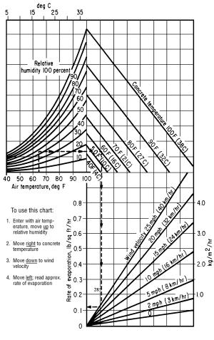
Figure 1 ACI 308-81
511.11 Slipform Construction of Bridge Railing. If Class HP concrete is specified, the Contractor may replace up to two-thirds of the No. 8 size coarse aggregate with No. 57 size coarse aggregate. The Engineer will submit the approved slipform concrete mix design to the Laboratory for record purposes.
If slipforming, provide finished concrete conforming to the following tolerances from plan dimensions:
|
Reinforcing steel cover |
-1/2 inch, +1/2 inch (-13 mm, +13 mm) |
|
Top width dimension |
-0, +1/4 inch (+6 mm) |
|
Bottom width dimension |
-0, +1/2 inch (+13 mm) |
|
Surface flatness |
1/4 inch in 10 feet (6 mm in 3 m) |
|
Vertical alignment (Deviation from a line parallel to the grade line) |
1/2 inch in 20 feet (13 mm in 6 m) |
Tie all joints and splices in bridge railing reinforcing steel. Before placing concrete, perform a slipforming dry run to verify reinforcing clearance and rigidity of the reinforcing cages. Adjust and stabilize the cage as necessary to establish the required clearances and to ensure the cage will not move during slipforming. The Contractor may add any additional diagonal reinforcing steel between the front and rear vertical reinforcing faces to establish the required rigidity.
Repair or patch honeycombing, cracking, tearing, and other defects immediately after concrete exits the slipform equipment. Completely fill defects with concrete without using water to smooth or close the surface.
After the concrete initially sets, but before any shrinkage cracks develop, saw control joints 1 1/4 inches (32 mm) deep into the perimeter of the parapet. Generally, initial set is within 6 hours of batching of the concrete. Ensure that all joints are sawed within 24 hours of placement. Saw control joints using an edge guide, fence, or jig to ensure that the joint is straight, true, and aligned on all faces of the parapet. The joint width shall be the width of the saw blade, a nominal 1/4 inch (6 mm). Caulk the control joints with a polyurethane or polymeric material conforming to ASTM C 920, Type S.
Slip formed concrete requires different slumps than those listed in Item 499 or other plan specified concrete. Provide a slump such that the concrete exiting the slipform does not pull but is stiff enough to prevent waviness and sags in the finished surfaces. Cure slipform concrete according 511.17, Method A. Because slipformed concrete has a low water-cement ratio, timely application of the water cure is critical in helping control shrinkage cracks.
Furnish platforms as necessary to protect traffic passing under the bridge from falling debris during the slipforming operation, to allow access for completing the finishing operation, and to allow the Engineer access to the outside of the parapet.
The Engineer will inspect the slipformed surface for horizontal cracking no earlier than 21 days after completion of the slipforming operation. Repair all horizontal cracks by epoxy injection. If a concrete sealer was applied, repair damage to the sealer after completing the epoxy injection.
511.12 Construction Joints. If construction joints are shown on the plans, place all concrete between consecutive joints in a continuous operation. Do not place concrete against a joint for at least 12 hours, or as required by 511.17.
Obtain the Director’s approval before placing any construction joint not shown on the plans or required by 511.10.
Before placing concrete, determine the location where the day’s concrete placing ends. If practical, end placing the day’s concrete perpendicular to the lines of principal stress and in regions of small shear. Do not install horizontal joints in concrete girders and beams.
Form construction joints using bulkheads with keyways. Locate keyways clear of exposed surfaces by approximately one-third the thickness of the joint.
Where practical, avoid horizontal joints in piers, abutments, and retaining walls, otherwise locate horizontal joints 2 feet (0.6 m) or more above the normal water level.
For construction joints not shown on the plans and above ordinary low water, in abutments, and in retaining walls that retain earth fills, install a 36-inch (1 m) strip of Type B waterproofing according to Item 512 to the back of the joint.
Avoid joints in cantilevered members.
Dampen the surface of the concrete of the horizontal construction joints immediately before placing adjoining concrete.
Place and protect horizontal construction joints between bridge slabs and superimposed curbs, parapets, sidewalks, and median strips in the same manner as the remainder of the slab. Cure the construction joints according to 511.17.
Avoid disturbing the bond between protruding reinforcing steel and the deck concrete. If using the curb areas to place the deck, tie and brace the reinforcing steel to prevent its movement.
Where walls or columns support slabs or beams, place concrete in wall or column to the bottom of the slab or beam and allow the concrete to settle for at least 2 hours before placing concrete in the slab or beam.
511.13 Work Stoppage. If the work is unexpectedly interrupted by breakdowns, storms, or other causes, rearrange the freshly deposited concrete to provide a suitable construction joint. If this joint occurs at a section with shear stress, prevent a plane of weakness by providing an adequate mechanical bond across the joint by forming a keyway, inserting reinforcing steel, or by some other means satisfactory to the Engineer.
511.14 Depositing Concrete Under Water. Except for cofferdam seals and drilled shafts, do not place concrete under water.
511.15 Depositing and Curing Concrete During Cold Weather. If placing concrete when the atmospheric temperature is 32 °F (0 °C) or less, or if weather forecasts predict these temperatures during the curing period, follow the procedures of this subsection.
Heat the water or aggregate, or both, as necessary to produce concrete with a temperature when placed of at least 50 °F (10 °C) but not greater than 70 °F (21 °C).
Place concrete against materials with a temperature of greater than 32 °F (0 °C). If necessary, heat the forms, reinforcing steel, and foundation materials before placing the concrete.
Maintain the concrete surface temperature between 50 and 100 °F (10 and 38 °C) for a period of not less than 5 days, except as modified in 511.15.C. After the minimum cure period of 5 days, reduce the concrete surface temperature at a rate not to exceed 20 °F (11 °C) in 24 hours until the concrete surface temperature is within 20 °F (11 °C) of atmospheric temperature.
Install sufficient high-low thermometers to readily determine the concrete surface temperature. For deck slabs, install high-low thermometers to measure deck bottom surfaces, deck fascia surfaces, and deck top surfaces.
Maintain the concrete curing temperature using a heated enclosure, insulated forms, or by flooding, except cure deck slabs less than 10 inches (250 mm) thick using more than just insulated forms.
Remove falsework and open cold weather concrete to traffic according to 511.17.
A. Heated Enclosure. Construct the heated enclosure to surround the top, sides, and bottom of the concrete. Construct strong and wind proof enclosures that contain adequate space to allow free circulation of air around the forms and concrete.
Before placing concrete, construct the enclosure and heating devices to the extent allowed by the concrete operation. As the concreting operation progresses and as soon as possible after placing concrete, complete construction of the enclosures and apply heat. Supply heat by a method that continuously maintains a reasonably uniform temperature throughout the enclosures and does not discolor the concrete.
Vent combustion-type heating devices outside the enclosure.
If dry heat, other than free steam, maintains the enclosure temperature, immediately cover exposed concrete with two thicknesses of burlap. Continuously wet the burlap and, except for required rubbing of the concrete, do not remove the burlap during the heating period.
If wood forms without liners are left in place more than 2 days after the placing of concrete, thoroughly wet the forms at least once each day for the remainder of the heating period. If forms are removed during the heating period, thoroughly drench the concrete with water and, for the remainder of the heating period, cover and wet the concrete with burlap as specified above.
B. Insulation. Install sufficient thermometers to readily determine the concrete surface temperature. If the surface temperature approaches 100 °F (38 °C), loosen or otherwise vent the forms or insulation to keep the surface temperature within the limits specified above. If insulation does not maintain the minimum required temperature, promptly enclose the concrete as specified in 511.15.A or flood the concrete as specified in 511.15.C.
Use a wind and water resistant insulating material. Ensure edges, corners, and other points of extreme exposure are adequately insulated. Place a tarpaulin or other Engineer approved waterproof cover over the insulation to protect the concrete top surface.
C. Flooding with Water. The Contractor may flood the concrete with water provided flooding does not damage the concrete. Heat the water to a temperature from 50 to 100 °F (10 to 38 °C). The Contractor may stop using heated water after 48 hours if the concrete remains flooded to a depth of 1 foot (0.3 m) above its highest elevation for at least the next 120 hours.
511.16 Removal of Forms. To facilitate finishing, remove forms from vertical surfaces that receive a rubbed surface finish as soon as the concrete has hardened sufficiently that rubbing will not damage it.
511.17 Curing and Loading. Remove falsework and open structures to traffic after the concrete has cured for the time specified by Table 511.17-1.
|
Table 511.17-1 |
|||
|
|
Span[1] |
Age of Concrete
in Days |
|
|
No Beam Test |
Beam Test[2] |
||
|
Removing Falsework |
Over 10 feet (3 m) |
14 |
5 |
|
10 feet (3 m) or less and all pier caps |
7 |
3 |
|
|
Traffic[3] |
Any |
14 |
7 |
|
[1] Span is defined as the horizontal distance between faces of the supporting elements when measured parallel to the primary reinforcement. |
|||
|
[2] Applicable only when the average modulus of rupture for two tests is not less than 650 psi (4.5 MPa). |
|||
|
[3] When placing Class HP concrete for a superstructure between October 15 and March 15, open the deck to traffic no sooner than 30 days after placement. |
|||
If the air temperature surrounding the concrete is maintained between 32 and 50 °F (0 and 10 °C), and if the provisions of 511.15 do not apply, maintain the concrete above 32 °F (0 °C) for 7 days or until a successful beam test except this time shall not be less than 5 days.
If a beam test is not performed, maintain the air temperature surrounding the concrete above 50 °F (10 °C) for 7 days. Extend the 7-day period and the times for removing falsework and opening to traffic one hour each hour the temperature of the air surrounding the concrete is below 50 °F (10 °C) and until the concrete has experienced 7 days, or 168 hours, of temperature above 50 °F (10 °C). Cure concrete as follows:
|
Location |
Curing Method [1] |
|
Superstructure concrete |
Method A |
|
Concrete to which sealer is applied |
Method A |
|
Construction joints |
Method A |
|
Top surface of Class HP concrete deck superstructure concrete |
Method A followed by Method B |
|
Concrete with waterproofing |
Method A or Method B |
|
All other concrete |
Method A or Method B |
|
[1] Method A is water curing. Method B is membrane curing. If using Method B on areas to be waterproofed, remove the curing membrane. |
|
Do not install compression rings on pier columns or similar items of construction for supporting falsework or subsequent construction until after a 72-hour curing period.
Do not apply loads to or perform work on new concrete until workers and materials will not damage the concrete or interfere with its curing. Allow at least 36 hours or until the average of two beam tests is greater than 650 pounds per square inch (4.5 MPa) before working on new concrete, but do not interfere with curing of new concrete.
Concrete curing methods are as follows:
A. Method A, Water Curing. With the exception of the top surface of deck superstructure concrete, protect surfaces not covered by forms immediately after final finishing with two thicknesses of wet burlap. Keep burlap wet for at least 7 days by the continuous application of water. If forms are removed before 7 days, immediately drench the exposed concrete with water and cover it with burlap. Continuously apply water to the burlap for the remainder of the curing period.
Instead of continuous application of water, with the exception of the top surface of deck superstructure concrete, the Contractor may cover the wet burlap with white polyethylene sheeting or plastic coated burlap blankets conforming to 705.06. Place plastic coated burlap blankets wet and with the burlap side against the previous layer of wet burlap. Sufficiently lap and secure adjoining plastic coated blankets or polyethylene sheets at the laps and edges to form a seal that maintains the concrete wet at laps and edges. Cover white polyethylene sheeting or plastic coated blankets containing holes or tears with an additional covering of plastic sheeting or blankets as directed by the Engineer.
Cover the top surface of deck superstructure concrete with a single layer of clean wet burlap after it is bullfloated if necessary, and finished. Keep the burlap wet by a continuous flow of water through soaker hoses and cover the hoses with a 4 mils (100 mm) white opaque polyethylene film for 7 days. After 7 days, allow the surface of the deck to dry.
After curing the top surface of Class HP deck superstructure concrete for 7 days, remove the burlap and standing water. Within 12 hours after removing the burlap, apply a curing membrane and cure the concrete according to Method B.
B. Method B, Membrane Curing. Immediately after the free water has disappeared on surfaces not protected by forms, apply curing material conforming to 705.07, Type 1 or 1D. If forms are removed before the end of the 7-day curing period, apply curing material on the concrete exposed by removing the forms.
Thoroughly agitate curing material immediately before use. Apply the membrane curing material at the rate of at least 1 gallon per 200 square feet (1 L/5 m2) of surface and in a fine mist to provide a continuous, uniform, and water impermeable film without marring the concrete surface. If the film is broken or damaged during the specified curing period, apply curing material as specified above to the damaged or affected areas.
Do not allow workers, materials, and equipment on the concrete during the curing period, unless adequately protecting the membrane curing material from damage.
511.18 Surface Finish. Immediately after removing forms, clean, dampen, and fill with mortar all cavities produced by form ties, honeycomb spots, broken corners or edges, and other defects. Use a mortar of the same proportions used in the concrete being finished. Substitute sufficient white cement for the regular cement in the mortar used to fill holes and perform other corrective work to produce finished patches of the same color as the surrounding concrete. Finish other contiguous exposed surfaces on the structure in a similar manner and to the extent required to produce a uniform appearance.
On all exposed surfaces, remove fins and irregular projections with a stone or power grinder, taking care to avoid contrasting surface textures.
A. Grout Cleaning. If grout cleaning is shown on the plans or necessary for corrective work, wet the concrete surface and then uniformly cover the concrete with a grout consisting of one part cement, 1 1/2 parts fine sand conforming to 703.03, and sufficient water to produce a mortar with the consistency of thick paint. In the quantity determined by the Engineer necessary to match the color of the concrete, use white portland cement in the grout. uniformly apply the grout with brushes or spray guns, completely filling air bubbles and holes. Immediately after applying the grout, vigorously scour the concrete surface with a cork or other suitable float. While the grout is still in a plastic condition and while the grout does not pull from the holes or depressions, finish the surface with a sponge rubber or other suitable float, removing excess grout. After the grout thoroughly dries, vigorously rub the surface with a dry burlap, removing dried grout until there is no visible film of grout remaining on the surface. Perform the entire cleaning operation of each area on the same day. Remove dark spots or streaks that remain after the cleaning operation using a fine grained silicon carbide stone. Stop rubbing with the silicon carbide stone before the surface texture changes. Unless otherwise directed by the Engineer, perform grout cleaning during the final project clean up.
B. Rubbed Finish. If a rubbed finish is shown on the plans, if possible, remove forms within 2 days after placing concrete. Finish the surface as specified above to correct defects. After the mortar used for finishing is thoroughly set, and for a minimum of 2 hours before starting the rubbed finish, thoroughly saturate the concrete with water.
Rub surfaces to be finished with a medium coarse silicon carbide stone until all form marks, projections, and irregularities are removed, all voids are filled, and a uniform surface is obtained. Leave the paste produced by rubbing in place. Other than water, do not apply additional material to the surface. After placing concrete above the finishing area, obtain the final finish by rubbing the concrete with a fine silicon carbide stone and water until the entire surface is of a smooth texture and uniform in color. Protect surfaces with a rubbed finish from damage caused by subsequent construction operations. If damaged, clean and refinish the surface as specified above.
511.19 Roadway Finish. Finish and test concrete deck slabs according to 451.12. Do not groove or broom finish a strip of surface 9 to 12 inches (220 to 300 mm) wide adjacent to curbs and barriers. Provide a broom drag finish on concrete deck slabs in the longitudinal or transverse direction.
The Engineer will approve the finishing machine. Provide a self-propelled machine with forward and reverse drive mechanisms that enable precise control of machine velocity in both directions. The machine shall have two rotating rollers, leveling augers, and either a vibrating pan or vibrating rollers. Furnish the Engineer documentation that verifies the machine is capable of varying the vibrating frequency for pans or rollers from 1500 to 5000 pulses per minute. Do not use vibrating rollers that have fins protruding more then 1/4 inch (6 mm) from the roller. Use a finishing machine capable of finishing transversely while traveling in both directions across the deck. Provide screeds capable of rising above the concrete surface. Provide a finishing machine capable of finishing the full width of the decks between curbs or parapet walls. The wheels of the finishing machine shall run on temporary riding rails adequately supported on the structural steel or falsework of the deck. Make the rail and rail supports of steel and arrange the rail and rail supports so that the weight of the finishing machine and the operator cause zero vertical deflection while traveling across the deck. Ensure the rail is straight, with no sections exceeding a tolerance of 1/8 inch in 10 feet (3 mm in 3 m) in any direction. Elevate support rails a sufficient distance above the slab to allow the simultaneous hand finishing of areas not machine finished. Fabricate and install rail supports to allow removal to at least 2 inches (50 mm) below the top of the slab. Fill holes formed by the removal of rail supports during the final finishing of the slab. Deliver and distribute the concrete at a uniform and adequate rate no more than 10 feet (3 m) directly in front of the finishing machine by suitable mechanical equipment.
511.20 Bridge Deck Grooving. After Class S concrete has cured, saw transverse grooves into the deck.
After water curing Class HP concrete and either before applying curing compound or some period after applying curing compound and before opening the bridge to traffic, saw transverse grooves into the deck. If sawing grooves after applying the curing compound, and concrete deck is less than 30 days old, reapply the curing compound after removing standing water, within 12 hours after sawing grooves in the deck.
The grooving of both Class S concrete and Class HP concrete shall be performed as specified below.
Use diamond blades mounted on a multi blade arbor on a self-propelled machine that was built for grooving of concrete surfaces. The groove machine shall have a depth control device that detects variations in the pavement surface and adjusts the cutting head height to maintain the specified depth of the groove. The grooving machine shall have devices to control alignment. Do not use flailing or impact type grooving equipment.
Begin and end grooves 9 to 12 inches (220 to 300 mm) from curbs, parapet toes, or deck edges, and saw grooves perpendicular to the bridge centerline.
Provide an experienced technician to supervise the location, alignment, layout, dimension, and grooving of the surface.
Saw grooves in a continuous pattern across the surface. Stop sawing 9 to 12 inches (220 to 300 mm) from any device in place in a bridge deck, such as scuppers or expansion joints. Stop sawing 2 inches to 2 feet from skewed expansion joints. Saw grooves in a random pattern spaced at 3/8 to 1 3/4 inch (10 to 45 mm), with 50 percent of spacings less than 1 inch (25 mm). Saw grooves approximately 0.15 inches (4 mm) deep and 0.10 inches (3 mm) wide.
At the beginning of each work shift, furnish a full complement of grooving blades with each saw that are capable of cutting grooves of the specified width, depth, and spacing.
If during the work, a single grooving blade on a machine becomes incapable of cutting a groove, continue work for the remainder of the work shift. The Contractor is not required to cut the groove omitted because of the failed blade. Should two or more grooving blades on a machine become incapable of cutting grooves, cease operating the machine until it is repaired.
Continuously remove all slurry and remaining residue from the grooving operation and leave the deck surface in a clean condition. Prevent residue from grooving operations from flowing across shoulders or across lanes occupied by public traffic or from flowing into gutters or other drainage facilities. Remove solid residue before the residue is blown by passing traffic or by wind.
Provide water as necessary to saw grooves according to this subsection.
511.21 Sidewalk Finish. After placing, strike off the concrete with a template and finish the concrete with a float to produce a sandy texture.
511.22 Sealing Joints and Cracks. After completing all curing operations and allowing the deck to thoroughly dry, seal the following areas with a high molecular weight methacrylate (HMWM) sealer conforming to Supplemental Specification 954 before opening the deck to traffic:
A. Transverse joints in the deck.
B. Joints between the concrete deck and steel end dams.
C. Longitudinal joints in the deck.
D. Longitudinal joints between the deck and safety curb, barriers, and parapets, etc.
E. Cracks discovered in the deck that will be checked on the top and bottom surface before opening the deck to traffic.
511.23 Class HP Concrete Testing. If included as a separate pay item, perform the following tests on the concrete.
A. Rapid Chloride Permeability Tests. Perform test according to AASHTO T 277. Take a minimum of three tests for decks containing less than 100 cubic yards (75 m3) of superstructure concrete. For all other decks, take six tests. Test deck superstructure concrete samples obtained from the actual concrete used.
Provide the Engineer with results of rapid chloride permeability tests at 28, 56, and 90 days.
B. Drying Shrinkage Tests. Perform test according to ASTM C 157 and at the frequency specified for rapid chloride permeability tests.
Provide the Engineer with results of drying shrinkage tests at 4, 7, 14, 28, 56, and 90 days.
C. Heat of Hydration Testing. Perform testing to determine the potential for length change due to thermal expansion and contraction. Immediately after placing the deck, install three thermometers into the fresh concrete at a location that is accessible for readings and representative of the overall deck pour. Locate the thermometer bulbs at 1 inch (25 mm) below the surface of the concrete, at approximately mid-slab, and at 1 inch (25 mm) above the bottom deck form. Leave the thermometers in place throughout the testing time. The Contractor may lubricate and place the thermometers in a thin plastic sheath to facilitate eventual removal.
Record temperatures at the following intervals:
|
Test Intervals |
Time |
|
2 hours |
first 12 hours |
|
3 hours |
second 12 hours |
|
4 hours |
second day |
|
8 hours |
third thru fifth day |
Record ambient air temperatures when taking concrete temperatures. Ensure that all testing is performed by a testing laboratory regularly inspected by the Cement and Concrete Reference Laboratories (CCRL). Furnish a copy of the last CCRL inspection report to the Engineer before the test slab pour.
If the Contractor uses Class HP 1 or 2 for parapets or substructures, perform three additional chloride permeability and drying shrinkage tests for the parapets or substructure concrete. If used for parapets, perform a heat of hydration test as described above with one thermometer located at 1 inch (25 mm) below the top of the parapet and a second thermometer located 19 inches (500 mm) below the top of the parapet, approximately midway between the front and back faces of the parapet. The Engineer will not require additional testing for units constructed with the same concrete mix option as the deck.
Tabulate test results on the attached form and forward the form to the Laboratory no later than 10 days following the completion of the tests.
After removing thermometers, drill out and fill the holes as approved by the Engineer.
511.24 Method of Measurement. The Department will measure the appropriate concrete item by the number of cubic yards (cubic meters) determined by calculations from plan dimensions, in place, completed and accepted.
The Department will not make deductions for the volume of the reinforcing steel, conduits, or structural steel other than beam flanges embedded in deck slabs. The Department will not make deductions for the volume of embedded timber or concrete piles.
Superstructure concrete includes the concrete in deflective parapets not having a metallic railing.
The Department may measure deck concrete by either volume or area using plan dimensions.
511.25 Basis of Payment. The Department will not pay for Class HP concrete Testing until the Laboratory receives all test results.
The Department will not pay for additional test slabs resulting from proportioning or batching sequence modifications for the Class HP.
If the contractor elects to use high early strength concrete, the Department will not pay additional costs associated with the use of these materials even if use is desirable to expedite the work.
The Department will not pay for additional reinforcing steel required to adequately stabilize the cages.
The Department will not pay for repairs to horizontal cracks by epoxy injection or, if a concrete sealer was applied, for repairs to the sealer after the completing the epoxy injection.
The Department will not pay extra for any type of surface finish specified in 511.18, the cost being considered as included in the price bid for concrete.
If the Contractor elects to saw the deck after applying the curing compound, the Department will not pay to reapply the curing compound.
All costs for sealing as specified in 511.22 is incidental to the appropriate concrete item. The Department will not make separate payment for sealing.
The Department will pay for accepted quantities at the contract prices as follows:
Item unit Description
511 Cubic
Yard Class ___
Concrete, ___
(Cubic Meter)
511 Cubic
Yard Class S Concrete,
(Cubic Meter) Bridge Deck
Square Yard
(Square Meter)
511 Cubic
Yard Class HP,
Concrete
(Cubic Meter) Bridge Deck
511 Square
Yard Class HP, Concrete
(Square Meter) Bridge Deck
511 Cubic
Yard Class HP,
Concrete Bridge
(Cubic Meter) Deck (Parapet)
511 Cubic
Yard Class HP,
Concrete
(Cubic Meter) Substructure
511 Lump Sum Class HP Concrete Test Slab
511 Lump Sum Class HP Concrete Testing
512.01 Description
512.02 Materials
512.03 General
512.04 Preparation of Surface
512.05 Primer Coat
512.06 Type A Waterproofing
512.07 Type B Waterproofing
512.08 Type D Waterproofing
512.09 Type 2 Membrane Waterproofing
512.10 Type 3 Membrane Waterproofing
512.11 Method of Measurement
512.12 Basis of Payment
512.01 Description. This work consists of applying the designated type of waterproofing to structures.
512.02 Materials. Furnish materials conforming to:
Asphalt cement.................................. 702.01 (PG 64 - 22)
Asphalt primer for................... 702.02 (RC-70 or RC-250),
.... waterproofing................................................... 702.05
Emulsified asphalt primer,.................. 702.04 (MS-2, SS-1)
Asphalt for waterproofing...................................... 702.06
Hot applied joint sealer........................................... 705.04
Type 3 membrane primer....................................... 705.04
Waterproofing fabric.............................................. 711.24
Sheet Type 2 membrane waterproofing................... 711.25
Sheet Type 3 membrane waterproofing................... 711.29
512.03 General. Apply an even and uniform coating of asphalt materials using brushes, squeegees, or spray equipment.
If using spray equipment, provide portable power pressure type spraying equipment capable of being moved to the location of the waterproofing operation.
Protect concrete surfaces not covered with waterproofing from overspray, spilling, or otherwise marring of the surface with the asphalt materials.
Ensure that the edge of any exposed application is sharply defined true to line with a uniform exposure.
512.04 Preparation of Surface.
A. Asphalt Materials. Remove concrete projections. Using wire brushes and clear water, remove dirt and the outside film of cement. Before applying asphalt materials, ensure that the concrete is clean and dry and the concrete temperature is at least 40 °F (4 °C).
B Membranes. Remove protrusions from the concrete. Sweep off dirt and dust, and blow the concrete clean. Fill joints or cracks greater than 3/8 inch (10 mm) wide with portland cement mortar. In addition to the above, remove oil and grease from surfaces for Type 3 membranes using water and a detergent designed to remove oil and grease from concrete. Flush residual detergent from the surface. Do not allow traffic on the cleaned surface.
512.05 Primer Coat. Apply the primer coat at the rate of 0.10 to 0.15 gallon (0.50 to 0.70 L) of asphalt material per square yard (square meter).
For primer coats applied between June 1 and September 1, use asphalt primer for waterproofing or emulsified asphalt primer conforming to 512.02.
For primer coats applied between September 1 and June 1, use asphalt primer for waterproofing conforming to 512.02.
If practical, apply asphalt emulsion using spray equipment.
If subjected to traffic, spread sand on the primer coat for protection. Broom off excess sand before applying asphalt waterproofing.
512.06 Type A Waterproofing. This type of waterproofing consists of one primer coat and at least two coats of asphalt material conforming to 702.06 to provide a total of at least 1 gallon (5 L) of asphalt per square yard (m2) on flat areas and at least 1/2 gallon per square yard (3 L/m2) on vertical or sloping surfaces. Start applying the waterproofing at the lowest point, and progress to a higher elevation. uniformly cover the surface except apply more asphalt in corners and over construction joints. Apply the asphalt material at a temperature from 250 to 350 °F (121 to 177 °C).
512.07 Type B Waterproofing. This type of waterproofing consists of one primer coat, three coats of asphalt material conforming to 702.06, and two layers of waterproofing fabric conforming to 711.24 applied as follows:
A. On a clean, dry, and well-primed surface, apply a thorough coating of asphalt at a temperature from 250 to 350 °F (121 to 177 °C).
B. Apply the coating at a rate of at least 1/3 gallon per square yard (1.5 L/m2) of surface.
C. While the asphalt is hot enough to penetrate the fabric, lay the fabric according to the following:
1. Surfaces Wider than Normal Fabric Strip. For the first strip, lay a half-width [normally 18 inches (0.5 m) wide] strip of fabric. For the second strip use a full-width strip of fabric, and lap the entire width of the first strip. Lap each succeeding strip 2 inches (50 mm) more than half its full width. Lap the fabric strips in the direction of water flow.
2. Surfaces with Same Width as Fabric Strip. For the first strip, lay a full-width strip. For the second strip, lay another full-width strip, covering the first.
Lay each strip without wrinkles, folds, or pockets. Thoroughly coat the strip with asphalt for the full width of the lap before laying the succeeding strip. Each application shall entirely conceal the texture of the fabric.
D. Apply a final coat of asphalt to provide a thorough covering for the fabric.
E. For all three coats, use a total of at least 1 gallon (5 L) of asphalt waterproofing material per square yard (m2).
Lap ends of fabric strips at least 12 inches (0.3 m), and stagger the end joints.
512.08 Type D Waterproofing. This type of waterproofing consists of one primer coat, one layer of waterproofing fabric conforming to 711.24 over joints, three coats of asphalt material conforming to 702.06, and two shingled plies of asphalt saturated waterproofing fabric conforming to 711.24.
Prime the surface to be waterproofed and allow the primer to dry. Fill joints and irregularities in the surface with asphalt cement. Lay a layer of fabric extending at least 9 inches (230 mm) on both sides of all joints. Leave the underside of this layer unbonded to the concrete surface.
Apply the asphalt at a temperature from 250 to 350 °F (121 to 177 °C) and conceal the texture of each layer of fabric with the asphalt. Use at least 1/3 gallon (1.5 L) of asphalt per square yard (m2) of surface for each application. Begin applying the asphalt and fabric at the low side or sides of the surface, and proceed toward the apex or high side so that water runs over and not against or along the laps of the fabric. Lay the fabric without wrinkles, folds, or pockets. Lap ends of fabric strips at least 12 inches (0.3 m), and stagger the end joints.
Start applying waterproofing by mopping asphalt on a surface slightly wider than half the width of the fabric strip. Immediately lay a half-width strip of the fabric onto the asphalt. Mop asphalt on this strip and an adjacent surface slightly wider than half the width of the fabric, and lay a full width of fabric that entirely covers the first strip. Mop asphalt on the second half of this second strip and an adjacent concrete surface and lay a third strip of fabric that laps the first strip at least 2 inches (50 mm). Continue this process of applying asphalt and laying fabric until the entire surface is covered and each strip of fabric laps the next to last strip already placed by at least 2 inches (50 mm). Finish laying fabric with a partial-width strip and mop the entire surface with asphalt.
512.09 Type 2 Membrane Waterproofing. This type of waterproofing consists of a rubberized asphalt and peel-and-stick waterproofing membrane 711.25. If the ambient temperature is below 50 °F (10 °C), use a manufacturer recommended primer coat for vertical surface application. After installing the primer coat, if required, remove the membrane’s release liner and place the adhesive side on the prepared concrete surface. Lay the membrane smooth and free of wrinkles. Lap joints in membranes by at least 1 inch (25 mm). Store membrane materials indoors at temperatures not to exceed 120 °F (49 °C).
For precast concrete three- and four-sided structures, install Type 2 membrane on the exterior vertical and exterior top horizontal surfaces.
512.10 Type 3 Membrane Waterproofing. This type of waterproofing consists of a primer coat conforming to 705.04 and a waterproofing membrane consisting of a high density asphalt mastic between two layers of polymeric fabric conforming to 711.29.
Keep membrane and primer materials dry before installation.
Heat the membrane primer in an oil primer heated, double-jacket kettle. Use a kettle that is clean and free of other materials with any obvious buildup scraped out. The Contractor may use a single-jacket kettle if the primer is capable of being heated in direct fire to the application temperature. Heat primers within the manufacturer’s recommended temperatures.
On bridges with curbs, apply the primer and membrane 3 inches (75 mm) up the curb face. On prestressed box beam bridges with no approach slab, apply the primer and membrane 6 inches (150 mm) over the ends of the beams. On prestressed and slab bridges with approach slabs, apply the primer 2 feet (600 mm) out onto the approach slab.
If the plans require a Type 3 membrane on the top exterior surface of precast concrete three- or four-sided structures, apply the primer and membrane to overlay the vertical exterior sides of the structure by 12 inches (300 mm).
Apply primer no further than 5 feet (1.5 m) in front of the membrane using a squeegee to fill all voids and imperfections. Apply membrane from the low to the high side of the surface. Apply an extra bead of primer at the edge of the membrane. Lap joints in membranes by at least 3 inches (75 mm). After installing the membrane over the entire surface, seal joints in the membrane by applying primer and smoothing with a V-squeegee.
512.11 Method of Measurement. The Department will measure Waterproofing, of the type specified, by the number of square yards (square meters) or on a lump sum basis.
512.12 Basis of Payment. The Department will pay for accepted quantities at the contract prices as follows:
Item unit Description
512 Square
Yard Type A
Waterproofing
(Square Meter)
Lump Sum
512 Square
Yard Type B
Waterproofing
(Square Meter),
or Lump Sum
512 Square
Yard Type D
Waterproofing
(Square Meter),
or Lump Sum
512 Square
Yard Type 2
Waterproofing
(Square Meter),
or Lump Sum
512 Square
Yard Type 3
Waterproofing
(Square Meter),
or Lump Sum
Item 513 STRUCTURAL STEEL MEMBERS
513.01 Description
513.02 Fabricator Approval Procedure
513.03 Levels of Fabricator Qualification
513.04 General
513.05 Fabricator Documentation Responsibility
513.06 Shop Drawings
513.07 Levels 1 through 6, Pre-Fabrication Meeting
513.08 Materials
513.09 Material Control
513.10 Care of Material
513.11 Workmanship and Straightening
513.12 Finish
513.13 Stiffeners
513.14 Fillers
513.15 Horizontally Curved Beams and Girders
513.16 Joints and Splices
513.17 Pin Holes
513.18 Pins and Rollers
513.19 Holes for High-Strength and Bearing Bolts
513.20 High-Strength Steel Bolts, Nuts, and Washers
513.21 Welding
513.22 Stud Shear Connectors
513.23 Threads for Bolts and Pins
513.24 Shop Assembly
513.25 Nondestructive Testing
513.26 Shipping, Storage, and Erection
513.27 Shop Coating
513.28 Cleaning ASTM A 709/A 709M, Grade 50W (345W) Steel
513.29 Method of Measurement
513.30 Basis of Payment
513.01 Description. This work consists of preparing shop drawings, furnishing and fabricating structural steel members, nondestructive testing, fabricator performed quality control, documentation, cleaning, shop coating, and erecting structural steel and other structural metals. The work also includes any work required to move existing steel structures to the plan location, making necessary repairs and alterations, and connecting or joining new and old construction.
The terms “main,” “secondary,” or “detail,” as referred to in Item 513, are defined as follows: “main” refers to material, members, and fasteners that are primarily stressed by live load and structure weight; “secondary” refers to material, members, and fasteners that do not directly support live load or main members; “detail” refers to essential non-structural material, members, and fasteners.
513.02 Fabricator Approval Procedure. Select fabricators that are listed by the Department before the Contract letting date as evaluated by the Office of Structural Engineering and pre-qualified according to Supplement 1078.
The Office of Structural Engineering may accept subletting of processes that require specialized machinery or knowledge. Submit written requests for subletting to the Office of Structural Engineering. The Office of Structural Engineering will determine if the process is uncommon and will evaluate the qualifications of the proposed sublet fabricator. The fabricator’s quality control staff shall witness and perform quality control of the sublet work.
513.03 Levels of Fabricator Qualification. There are eight levels of fabricator qualification. The Office of Structural Engineering will classify each fabricator at the highest level of fabrication it is qualified to perform.
|
Level |
Description of Capabilities |
|
SF |
Standard fabricated members
described and paid for as Item 516, 517, and 518 and detailed by standard
bridge drawings. Material and
fabrication acceptance by certification with random Department audits of the
work and documentation. |
|
UF |
unique fabricated members
not covered by standard bridge drawings and not designed to carry tension
live load. Examples include curb
plates, bearings, expansion joints, railings, catwalk, inspection access,
special drainage, or other products.
Examples also include retrofit cross frames, retrofit gusset plates,
retrofit lateral bracing, or other miscellaneous structural members not
included in Levels 1 through 6.
Quality assurance of shop drawings, material test reports, and inspection
according to Item 513, SF Level. |
|
1 |
Single span, straight,
rolled beam bridges without stiffeners, Secondary and Detail materials
designed to carry tension live loads such as retrofit moment plates. Case II Loading. Quality assurance of shop drawings, material test reports, and
inspection according to Item 513, Levels 1 through 5. |
|
2 |
Multiple span, straight,
rolled beam bridges without stiffeners.
Case II loading. Quality
assurance of shop drawings, material test reports, and inspection according
to Item 513, Levels 1 through 5. |
|
3 |
Single or multiple span,
straight, dog legged, or curved, rolled beam bridges including
stiffeners. Case I or II
Loading. Quality assurance of shop
drawings, material test reports, and inspection according to Item 513, Levels
1 through 5. |
|
4 |
Straight or bent welded
plate girder bridges. Case I or II
loading. Quality assurance of shop
drawings, material test reports, and inspection according to Item 513, Levels
1 through 5. |
|
5 |
Straight, curved, haunched,
or tapered welded plate girder bridges.
Case I or II loading. Quality
assurance of shop drawings, material test reports, and inspection according
to Item 513, Levels 1 through 5. |
|
6 |
Truss bridges, fracture
critical bridges, fracture critical members, or fracture critical components
new or retrofitted. Case I or II
loading. Quality assurance of shop
drawings, material test reports, and inspection according to Item 513, Level
6. |
513.04 General. Item 501 includes general information pertaining to structural steel fabrication and erection. Shop painting shall conform to Item 514.
Perform all steel fabrication including the shop application of coatings in a pre-qualified structural steel fabricating shop consisting of adequately sized permanent buildings with equipment, heat and light, and experienced personnel to satisfactorily perform all necessary operations. Perform flame cutting, air carbon-arc gouging, cambering, welding, cleaning, and painting inside permanent buildings that are maintained at the required environmental conditions. The fabricator may perform shop assembly of large pieces for fit-up of field connections outdoors. These provisions will not apply to steel requiring fabrication at the bridge site in the repair, alteration or extension of an existing structure.
If repairing, extending, or altering existing structures, take measurements of the existing structure as required to accurately join old and new work. Include these measurements on shop drawings. Measurements shown on the plans that indicate the extent and nature of repair, alterations or extension shall not relieve the Contractor of this responsibility.
At least two weeks before starting shop fabrication, the fabricator shall notify the Office of Structural Engineering and furnish a proposed fabrication schedule for the work.
Unless the Office of Structural Engineering provides a written waiver of a hold or witness point inspection, the fabricator shall store members completed during the inspector’s absence in a manner that allows the inspector to completely and safely inspect the finished work.
The fabricator shall not ship fabricated members performed under Item 513, UF Level or Levels 1 through 6 from the shop without prior hold point inspections unless the Office of Structural Engineering waives the inspection. The Office of Structural Engineering will not conduct the scheduled final inspection until the fabricator completes and inspects with documentation, final fabrication and shop coatings and the Contractor documents approval of shop drawings and material test reports.
The Office of Structural Engineering will not conduct a final fabrication inspection of SF Level members. Instead, the Office of Structural Engineering will conduct random inspections during the fabricator’s work.
The fabricator shall provide an office with the following attributes:
A. A minimum floor area of 120 square feet (11 m2).
B. A minimum ceiling height of 7 feet (2.1 m).
C. Adequate working and storage facilities with one locking file cabinet for the exclusive use of the Department’s inspector, lighting, and electrical outlets.
D. Provisions for heating to a minimum temperature of 68 °F (20 °C) and adequately ventilated.
E. A telephone with direct access to an outside trunk line for the exclusive use of the inspector.
If using steel stamps for identification purposes, use the “mini-stress” or “stressless” type.
513.05 Fabricator Documentation Responsibility. The fabricator shall keep and maintain documentation records as specified in Supplement 1078.
At the Department’s request, provide access to the above documents for audit, inspection, and copying.
513.06 Shop Drawing. Provide shop drawings conforming to 501.04 and the following requirements:
Include details, dimensions, size of materials, match mark diagrams for field connections, a diagram identifying, by some unique mark, each area of a welded splice to be covered by a single radiograph, and other information necessary for the complete fabrication and erection of the metal work.
For multiple span beam and girder bridges, include an overall layout with dimensions showing the relative unloaded vertical and horizontal position of beam or girder segments with respect to a full length base or work line. Account for camber and horizontal curvature of the beams or girders, and the effect of deck surface profile in this layout. Show required offsets for vertical and horizontal curvature at approximately each one-fourth of span length, at field splices, and at bearing points. For horizontally curved members, show the offset to a baseline strung from end to end of the member, every 10 feet (3 m) of length.
Identify the grade (ASTM designation), CVN, fracture critical, or any special testing requirements for each piece of steel. Identify pieces made of different grades of steel with different assembling or erecting marks, even if the pieces have identical dimensions and detail.
Identify the welding procedure by the WPS number at each joint and the location and identification numbers of all radiograph tests.
513.07 Levels 1 through 6, Pre-Fabrication Meeting. After providing the notice and schedule required by 513.04 and at least 7 days after the Department receives shop drawings, conduct a pre-fabrication meeting at the fabricator’s facilities, or another location agreed to by all parties. The fabricator and its quality control specialists for fabrication and painting, the inspector, and the Contractor, or its designated representative, shall attend the meeting. The purpose of this meeting is to review any fabrication issues, including information on shop drawings, inspection, hold or witness points, unique fabrication items, special processes, and both the fabrication and project schedule. The fabrication quality control specialist shall conduct the meeting and record and distribute meeting minutes that document all issues discussed. Fabrication may begin after the pre-fabrication meeting is complete.
513.08 Materials. Furnish materials conforming to 501.07.
513.09 Material Control. Identify and mark each piece of steel according to the shop drawings and the following requirements.
Immediately after removing steel that is furnished in tagged lifts or bundles, mark the individual pieces of steel with the ASTM A 6/A 6M specification identification color code and heat number.
The fabricator may furnish material from stock that is marked with the heat number and mill test report.
If separated from the full-size piece furnished by the supplier, mark excess material placed in stock for later use with the heat number and, if provided, with the ASTM A 6/A 6M specification identification color code.
During fabrication, clearly and legibly mark the specification identification color code and heat number on each piece of steel.
Before cutting steel into smaller size pieces, clearly and legibly mark each smaller size piece with the ASTM A 6/A 6M specification identification color code and heat number.
Unless otherwise approved by the inspector, mark pieces of steel that will be subject to fabricating operations such as blast cleaning, galvanizing, heating for forming, or other operations that may obliterate paint color code and heat number markings with steel stamps or with a substantial tag firmly attached to the piece of steel. At locations acceptable to the Office of Structural Engineering, stamp the heat numbers into main material tested for CVN.
Issue cutting instructions by cross-referencing the assembly marks shown on the shop drawings with the corresponding item covered on the mill purchase order. The fabricator’s system of assembly-marking individual pieces of steel and issuing cutting instructions shall provide a direct reference to the appropriate mill test report.
The fabrication quality control specialist shall provide the Engineer with a letter documenting that the fabricator performed material control according to this specification.
513.10 Care of Material. Store structural material at the shop or field above the ground, upon platforms, skids, or other supports. Use straight structural steel with clean and dry surfaces before working it in the shop. Before using, clean all rusted or corroded material. Only use this material if it conforms to ASTM A 6/A 6M thickness tolerances after cleaning.
513.11 Workmanship and Straightening. If necessary to straighten rolled material, use methods that will not damage the member. If carefully planned and supervised, apply localized heat for straightening. Do not allow the temperature of the heated area to exceed 1150 °F (620 °C) as controlled by pyrometric stick or thermometers. Do not quench to accelerate cooling. Do not kink or offset the material if using mechanic or hydraulic force to camber or strengthen material. Do not cold bend fracture critical materials.
Camber rolled beams as shown on the plans in the pre-qualified fabricating shop using heat or hydraulic jacks. Control heating as specified above and follow a formal shop heating procedure. Camber plate girders by trimming web plates before assembly. During fabrication, shipping, and erection, support and handle members to maintain camber.
Fabricate structural steel to within the dimensional tolerances specified by Articles 3.5 and 9.19 of the AASHTO/AWS Bridge Welding Code, with the following modifications:
A. Waviness, the deviation of the top or bottom surface of a flange from a straight line or plan curvature, shall not exceed 1/8 inch (3 mm) when the number of waves in a 10-foot (3 m) length is four or less, or 1/16 inch (1.6 mm) when more than four, but sharp kinks or bends shall be cause for rejection.
B. For the measurement of camber during lay down, position the bearing points both horizontally and vertically to plan dimensions ±1/8 inch (±3 mm).
C. Measure camber as the vertical offset between the steel and the common base line extending from abutment bearing to abutment bearing. The maximum camber tolerance at mid-span shall be 0 inch (0 mm) and the greater of +3/4 inch (+19 mm) or the designed haunch height. Prorate the maximum camber tolerance at mid-span between the center of the span and each adjacent bearing to provide a smooth unbroken curve.
D. Permissible difference in horizontal curvature of top and bottom flange at any point on centerline of member, when measured as specified in 3.5.1.4, shall not exceed 3/8 inch (10 mm)
513.12 Finish. Plane sheared edges of all main material to a minimum depth of 1/4 inch (6 mm) except for ASTM A 709/A 709M, Grade 36 (250) steel having a thickness of 5/8 inch (16 mm) or less. Remove fins, tears, slivers, and burred or sharp edges from steel members by grinding. If these conditions appear during the blasting operation, re-grind and re-blast the steel members to the required surface profile.
The fabricator may flame cut structural steel. Provide a smooth surface, free from cracks and notches, and use a mechanical guide to provide an accurate profile. Roll and flame cut surfaces according to the AASHTO/AWS Bridge Welding Code, as amended by Supplement 1011.
Provide a surface finish for bearing and base plates and other bearing surfaces that contact each other or concrete according to ANSI B46.1, Surface Roughness, Waviness and Lay, Part I.
|
ANSI B46.1 |
|
|
Steel slabs |
2000 mil (50.0 mm) |
|
Heavy plates in contact in shoes to be welded |
1000 mil (25.0 mm) |
|
Milled ends of compression members, milled or ground ends of stiffeners and fillers |
500 mil (12.5 mm) |
|
Bridge rollers and rockers |
250 mil (6.4 mm) |
|
Pins and pin holes |
125 mil (3.2 mm) |
|
Sliding bearings |
125 mil (3.2 mm) |
513.13 Stiffeners. Place the bearing end of bearing stiffeners flush and square with the web and in a manner so at least 75 percent of the area of the bearing end is in contact with the inner surface of the flange. The other end of the bearing stiffener shall have a tight fit as defined below. Position bearing stiffeners to be vertical after erection. Weld intermediate stiffeners that are not used in pairs to the compression flange, and provide a tight fit for the tension flange. Weld intermediate stiffeners connected to cross frame angles to the top and bottom flange.
A tight fit is defined as the contact between the stiffener and flange over some portion of the end of the stiffener and having no gap greater than 1/16 inch (1.6 mm).
Clip stiffeners 2 1/2 inches (65 mm) along the web and 1 inch (25 mm) along the flange to clear flange-web welds and fillet or rolled shapes.
When attaching stiffeners to the web and flanges, do not extend welds to the edge of the stiffeners or into the clip area. Terminate these welds 1/4 ± 1/8 inch at the flange connections and 1/2 ± 1/4 inch at the web connection.
513.14 Fillers. Detail the shop drawings to show fill plates that compensate for the misalignment of abutting elements due to differences in thickness of flanges and webs at the splice locations. Detail the fill plates to the nearest 1/16 inch (1.6 mm) in thickness, but not less than 1/8 inch (3 mm) thick. However, in the final shop assembly, furnish fills of sufficient thickness to compensate for misalignment of abutting elements due to standard rolling mill tolerances or due to differences in thicknesses of flanges and webs at the splice location. The actual fills used shall compensate for differences in total thickness or relative positions of more than 1/16 inch (1.6 mm) but with no fills less than 1/8 inch (3 mm) thick. Provide fill plates in bolted joints that are flush with the perimeter of the splice plates.
513.15 Horizontally Curved Beams and Girders. If members are to be heat curved, submit the detailed procedure, including necessary calculations, to the Office of Structural Engineering. Obtain the Office of Structural Engineering’s acceptance of the procedure before starting this work.
Curve beams and girders using heat according to AASHTO Standard Specifications for Highway Bridges, except that the fabricator may cut flanges for girders to obtain the required alignment.
513.16 Joints and Splices. In bolted construction where tension or flexural members are spliced, maintain a clearance of not more than 1/4 inch (6 mm) between the abutting surfaces of spliced members. For spliced compression members, face the abutting surfaces to provide a uniform bearing when properly aligned and completely bolted.
In welded construction, prepare abutting surfaces as shown on the shop drawings. Verify the preparation for field welded butt joints in main members by a complete shop assembly according to 513.24.
513.17 Pin Holes. Bore pin holes after the member is fabricated and true to size, at right angles to the axis of the member and parallel to each other. Pin holes for up to 5-inch (127 mm) diameter pins shall not exceed the pin diameter by more than 0.020 inch (0.51 mm) and pin holes for larger pins shall not exceed the pin diameter by more than 0.031 inch (0.79 mm).
513.18 Pins and Rollers. Use pins and rollers made from cold rolled steel, accurately turned to size, straight and smooth, and entirely free from flaws. Pins over 9 inches (230 mm) in diameter shall be annealed. In pins larger than 9 inches (230 mm) in diameter, bore a hole not less than 2 inches (50 mm) in diameter the full length of the axis. Furnish one pilot and one driving nut for each size of pin.
513.19 Holes for High-Strength Bolts and Bearing Bolts. Provide cylindrical holes, perpendicular to the member, clean cut, and free of ragged edges. Remove burrs by countersinking not more than 1/16 inch (1.6 mm) or by grinding. Provide finished holes with a diameter not larger than the nominal diameter of the bolt plus 1/16 inch (1.6 mm). The hole diameter shall not vary by more than 1/32 inch (0.8 mm) from a true circle for 85 percent of the holes in a contiguous group, and not more than 1/16 inch (1.6 mm) for the remainder.
Punch holes using a die with a diameter not exceed that of the punch by more than 1/16 inch (1.6 mm). Ream and drill holes using twist drills and twist reamers. Wherever possible, direct the reamer by mechanical means.
Sub-drill holes 3/16 inch (5 mm) less in diameter than the nominal diameter of the bolt, and ream the holes to size with the parts assembled, except:
A. The fabricator may sub-punch main material conforming to ASTM A 709/A 709M, Grade 36 (250) steel that is less than 3/4 inch (19 mm) thick, and Grade 50 (345) or 50W (345W) steel that is less than 5/8 inch (16 mm) thick.
B. The fabricator may drill full-size holes in materials assembled and adequately clamped together.
C. The fabricator may punch full-size hoes in secondary and detail material conforming to ASTM A 709/A 709M, Grade 36 (250) steel that is less than 3/4 inch (19 mm) thick, and Grade 50 (345) or 50W (345W) steel that is less than 5/8 inch (16 mm) thick.
D. The fabricator may make assemblies such as floor beams connected to girders and rolled beam spans connected by diaphragms through steel templates.
Place all sub-punched or sub-drilled holes with sufficient accuracy such that after assembling (before reaming) a cylindrical pin 1/8 inch (3 mm) smaller than the nominal size of the punched hole may be entered perpendicular to the face of the member without drifting in not less than 75 percent of the contiguous holes in the same plane. All holes shall allow a pin 3/16 inch (5 mm) smaller than the nominal size of the punched holes to be inserted in the above manner.
Do not plug located holes without written approval from the Office of Structural Engineering.
Provide steel templates with hardened bushings in holes that are accurately located in relation to the centerline of the connection as inscribed on the template. The fabricator is not required to use hardened bushings when using a roto-broach, shell drill, or other similar tool, to make the holes.
Ream and drill holes through multiple piles only if the plies of the joint are held tightly together with bolts or clamps and if sub-punched or sub-drilled, only if the joint is pinned. Disassemble and clean the piles of burrs and shavings before final assembly.
The Contractor may drill or punch bolt holes full sized in unassembled pieces or connections, including templates for use with matching sub-sized and reamed holes, using suitable numerically controlled (N/C) drilling or punching equipment. If using N/C drilling or punching equipment, demonstrate the accuracy of the drilling or punching procedure to the inspector according to 513.24.
After holes are reamed or drilled full size, 85 percent of the holes in any contiguous groups shall have no offset greater than 1/32 inch (0.8 mm) between adjacent plies. The remainder of the holes shall not be offset more than 1/16 inch (1.6 mm) between adjacent plies.
If requested in writing, the Office of Structural Engineering may consider other methods of preparing holes for high-strength bolts.
513.20 High-Strength Steel Bolts, Nuts, and Washers. Provide high-strength steel bolts, nuts, and washers conforming for all bolted connections including erection bolts for cross frames and lateral bracing to 711.09.
A. General. Provide the Engineer with access to the work for observing the installation and the tightening and checking of the bolts.
Determine the required bolt length by adding the value from Table 513.20-1 to the grip. The table values include an allowance for manufacturing tolerances and provide a bolt length for threads to protrude through the nut. Add 5/32 inch (4 mm) for each hardened flat washer used and 5/16 inch (8 mm) for each beveled washer used. Adjust the length, as determined by Table 513.20-1, to the next longer 1/4 inch (6 mm); when installed, the end of the bolt shall be flush with or project several thread lengths outside the face of the nut.
TABLE 513.20-1
|
Bolt Size |
To determine
required bolt length, add to
grip[1] |
|
(inches) |
(inches) |
|
1/2 |
11/16 |
|
5/8 |
7/8 |
|
3/4 |
1 |
|
7/8 |
1 1/8 |
|
1 |
1 1/4 |
|
1 1/8 |
1 1/2 |
|
1 1/4 |
1 5/8 |
|
1 3/8 |
1 3/4 |
|
1 1/2 |
1 7/8 |
|
[1] Total thickness of all connected material excluding washers. |
|
TABLE 513.20-1M
|
Bolt Size |
To determine
required bolt length, add to
grip[1] |
|
(mm) |
(mm) |
|
M16 |
24 |
|
M20 |
28 |
|
M22 |
31 |
|
M24 |
35 |
|
M27 |
38 |
|
M30 |
41 |
|
M36 |
47 |
|
[1] Total thickness of all connected material excluding washers. |
|
Use bolts, nuts, and washers with a residual coating of lubricant when received. Bolts, nuts, and washers without their original lubrication shall not be used.
B. Preparation. With the exception of metalizing, galvanizing, and both organic zinc and inorganic zinc primers, remove coatings from joint surfaces, including surfaces adjacent to the bolt heads, nuts, and washers. Remove lacquer, dirt, oil, loose scale, rust, burrs, pits, and other substances or defects that prevent solid seating of the parts or interfere with the development of complete frictional contact. Do not place gaskets or other yielding material between joint surfaces.
C. Installation. For each bolt, place a hardened washer under the element (nut or bolt head) turned in tightening. If an outer face of the bolted parts has a slope of more than 1:20 with respect to a plane normal to the bolt axis, use a smooth beveled washer to compensate for the lack of parallelism.
If necessary, the Contractor may clip washers, at one location, not closer than seven-eighths of the bolt diameter from the center of the washer.
During final assembly of the parts to be bolted, first install a sufficient number of drift pins to provide and maintain accurate alignment of holes and parts, then a sufficient number of bolts tightened to a snug tight condition to bring all the parts of the joint into complete contact. Replace any bolts that were installed before installing drift pins. Before releasing the member from the hoisting equipment, fill half the holes with drift pins and bolts tightened to a snug tight condition in at least 50 percent of the holes (preferably, half pins and half bolts) but use at least two drift pines in each flange and web of each beam or girder. Install bolts starting at the most rigidly fixed or stiffest point and progress toward the free edges.
Use cylindrical drift pines that are not more than 1/32 inch (0.8 mm) smaller than the hole diameter.
Bolts are snug tight when an impact wrench begins to impact the nut or when a man applies full effort using an ordinary spud wrench.
Install bolts in the remaining open holes and tighten the bolts to a snug tight fit, after which all bolts shall be tightened completely by the turn-of-nut method.
Where difficulty is experienced with the fit of the connection and the bolts are used to draw the elements into contact, check all bolts in the affected portion of the connection for a sustained snug tight condition.
Replace drift pins with completely tightened bolts only after all the remaining holes are filled with completely tightened bolts.
Do not field ream holes drilled full size during fabrication.
After bolts are snug tight, the wrench operator shall match-mark the outer face of the nut with the flush or protruding portion of the bolt using a crayon or paint. The Engineer will use the match-marks to determine the relative rotation between the bolt and nut during final tightening using the turn-of-the-nut method.
Commence tightening at the most rigidly fixed or stiffest point and progress toward the free edges, both in the initial snugging up and in the final tightening. If required because of wrench operation clearances, tightening may be done by turning the bolt. If used, provide impact wrenches of adequate capacity to perform the required tightening each bolt in approximately 10 seconds.
Do not reuse galvanized A 325 bolts. Re-tightening previously tightened bolts that became loose by tightening adjacent bolts is not reuse.
Follow the additional bolting requirements in 513.26.
D. Bolt Tension. When all bolts in the joint are tight, the minimum bolt tension for each bolt size is shown in Table 513.20-2.
TABLE 513.20-2
|
Bolt Size (inches) |
Bolt Tension[1] (kips), minimum
A 325 |
|
1/2 |
12 |
|
5/8 |
19 |
|
3/4 |
28 |
|
7/8 |
39 |
|
1 |
51 |
|
1 1/8 |
56 |
|
1 1/4 |
71 |
|
1 3/8 |
85 |
|
1 1/2 |
103 |
|
[1] Equal to 70 percent of specified minimum tensile strengths of bolts, rounded off to the nearest kip. |
|
TABLE 513.20-2M
|
Bolt Size (mm) |
Bolt
Tension[1] (kN),
minimum A 325M |
|
M16 |
91 |
|
M20 |
142 |
|
M22 |
176 |
|
M24 |
206 |
|
M27 |
267 |
|
M30 |
327 |
|
M36 |
475 |
|
[1] Equal to 70 percent of specified minimum tensile strengths of bolts, rounded off to the nearest kN. |
|
TABLE 513.20-3 NUT ROTATION FROM SNUG TIGHT CONDITION
|
|
Disposition of Outer Faces
of Bolted Parts |
||
|
Bolt
Length (as measured from underside of head to extreme end of point) |
Both faces normal to bolt axis |
One face normal to bolt axis and other face sloped not more than 1:20 (bevel washer not used) |
Both faces sloped not more than 1:20 from normal to bolt axis (bevel washer not used) |
|
Up
to and including 4 diameters |
1/3 turn |
1/2 turn |
2/3 turn |
|
Over
4 diameters but not exceeding 8 diameters |
1/2 turn |
2/3 turn |
5/6 turn |
|
Over
8 diameters but not exceeding 12 diameters |
2/3 turn |
5/6 turn |
1 turn |
Attain the bolt tension specified in Table 513.20-2 by tightening all bolts, the applicable amount of nut rotation specified in Table 513.20-3 by the turn-of-nut method.
Nut rotation is relative to bolt, regardless of the element (nut or bolt) being turned. Tighten bolts requiring 1/2 turn and less within ±30 degrees and tighten bolts requiring 2/3 turn and more within ±45 degrees.
E. Inspection.
1. The Engineer will inspect the first completed connection of each bridge according to 513.20.E.2 below and subsequent connections the Engineer deems necessary. Thereafter, where the Engineer has approved the joint compactness and snug-tight condition of bolts prior to bolt tightening by the turn-of-nut method, the bolt tension as required in Table 513.20-2 shall be considered as attained if the amount of nut rotation specified by Table 513.20-3 is verified by the required match-marking.
2. Furnish and use manual torque wrenches to inspect bolts. Perform test to the satisfaction of the Engineer. Calibrate the inspection torque wrenches at least once each workday using a device, approved by the Engineer, and capable of indicating bolt tension. Use three bolts, placed and tensioned individually, representative of the grade, size, length, and condition used in the structure to determine the job inspection torque according to 513.20.E.3. Place a washer under the part being turned.
3. Tighten each of the three representative bolts, using any convenient manner, to the tension shown in Table 513.20-2. Then, using the inspection wrench, apply a slow steady pull to the tightened bolt and measure the torque required to turn the nut or head 5 degrees, approximately 1 inch (25 mm) at a 12-inch (300 mm) radius in the tightening direction. Use the average torque measured in the tensioning of the three bolts as the job inspection torque.
4. With the Engineer present, randomly select for inspection two bolts or 10 percent of the bolts, whichever is greater, from each connection represented by the 3-bolt sample described in 513.20.E.2. Using the inspection wrench, apply the job inspection torque in the tightening direction. The Engineer will accept the connection if the job inspection torque does not turn the nut or bolt head. If the job inspection torque turns a nut or bolt head, apply the job inspection torque to all the bolts in the connection and reinspect the connection as described above.
F. Calibration Devices. The manufacturer of the calibration device or a qualified testing laboratory shall periodically examine each calibration device at least once each year and other times if requested by the Engineer. After calibration, the manufacturer or testing laboratory shall certify that each calibration device accurately indicates the actual bolt tension.
513.21 Welding. Perform welding by the shielded metal-arc, submerged arc, flux cored arc, or stud welding process. Only shielded metal arc (stick) welding is prequalified. All other welding processes require testing and approved by the Office of Structural Engineering. Consideration will be given to other methods of metal-arc welding if a written request is submitted to the Office of Structural Engineering.
In other respects, the AASHTO/AWS Bridge Welding Code, as amended by Supplement 1011, shall govern the work.
Post copies of the shop welding procedures at each welding location.
Weld only fracture critical and main members when the fabrication quality control specialist and inspectors are physically at the facility. The fabricator shall not perform fracture critical welding without prior scheduling with the fabrication quality control specialist and the inspector. The fabrication quality control specialist shall witness the minimum percentages specified in Supplement 1078 and shall check all welding processes.
For non-fracture critical welds, the fabrication quality control specialist shall perform frequent inspections, and check all welding processes.
513.22 Stud Shear Connectors. Perform stud welding according to the AASHTO/AWS Bridge Welding Code, as amended by Supplement 1011, and this subsection.
In addition to the stud bend tests of Article 7.6.6.1 of the AASHTO/AWS Bridge Welding Code, perform bend tests of stud shear connectors at the start of each workday, when welding has been interrupted for an hour or more, when changing grounds, when changing weld settings, and when changing cable loop due to arc blow. Do not weld more than 500 studs without the welds being field bend tested in accordance with the specified procedure. The Contractor may leave in the bent position tested studs that show no sign of failure, as determined by the Engineer.
513.23 Threads for Bolts and Pins. Threads for pins shall conform to the unified Standard Series ANSI B1.1-UNC (ANSI B1.13M) Class 2A (6g) for external threads and Class 2B (6H) for internal threads, except that pin ends having a diameter of 1 3/8 inches (35 mm) or more shall be threaded 6 threads to the inch (4.23 mm/thread).
513.24 Shop Assembly. Remove paint, grease, oil, rust, loose mill scale, and protruding edges or burrs from all contact surfaces. Unless waived by the Office of Structural Engineering, do not assemble and weld flanges and webs to form girders or other similar members and do not accomplish fabrication or assembly that interferes with the repair of a butt weld until the fabrication quality control specialist for the A rated fabricators or the inspector for B and C rated fabricators examines and approves radiographs of all butt welds in the component parts.
Perform fit-up work with the members assembled in unloaded positions as shown on the shop drawing layout required by 513.06. During shop assembly, adequately support members, especially at joints, to prevent misalignment or deflection and designate supports that prevent settlement during the fit-up, reaming or drilling of connections. The fabrication quality control specialist shall maintain records of the actual horizontal and vertical dimensions and relative positions of each assembly for each offset required by 513.06 and, upon request, furnish a copy to the inspector. Reposition members that become a part of two assemblies for the second assembly to the dimensions recorded for the first assembly.
Using steel stamps, match-mark all connecting parts assembled in the shop for the purpose of reaming or drilling of holes for field connections or for fit-up of field welded connections before disassembly. Punch mark bearing centerlines.
Continuous beam and plate girders, including sections adjacent to hinged, pin connected, sliding, or rocker bearing joints, shall have at least three adjacent segments assembled, and holes reamed or drilled while assembled. Check the fit-up of field welded connections by similar shop assembly.
Shop assemble longitudinal or transverse beams and girders that are either framed or connected by diaphragms and floor beams to check fit-up of connections to be field welded, or to ream or drill holes for bolted connections. Assemble trusses in lengths of at least three abutting panels before drilling or reaming field connections.
Include deck plates in the final shop assembly of bridges that involve railroad deck plates, even if welding of these deck plates takes place in the field.
If the fabricator elects to use numerically controlled drilling or punching, the required assembly shall be performed as specified above. The Office of Structural Engineering will consider the Contractor’s written request to use other methods of checking hole alignment and match marking. If the Office of Structural Engineering does not consider, or disapproves the fabricator’s proposed methods of assembly, perform the work according to 513.19 and 513.24.
After fabrication, shop assemble deck expansion devices to check fit-up, straightness, and roadway cross-slope changes. Full width assembly is required with phased construction if expansion devices have interlocking fingers or have mechanical devises that require exact field alignment.
The fabricator may fabricate part-width deck segments without the required shop assembly under the following conditions:
A. The plans require a phased construction sequence.
B. Shop drawings incorporate a lay down, similar to 513.06, defining vertical offset dimensions from a full length common baseline to all roadway changes including sidewalks, rounding, crowns, and field splice points of the expansion device.
Secure parts not completely assembled in the shop with temporary bolts to prevent damage in handling and shipping. In the shop, bolt field splice plates into final position shift the splice plates laterally with respect to their final position so that the ends of the plates are flush with the ends of the member. Without the Office of Structural Engineering’s written acceptance, do not weld or tack-weld to bolted assemblies. Perform authorized welding according to 513.21.
513.25 Nondestructive Testing. Nondestructive testing shall conform to the AASHTO/AWS Bridge Welding Code, as amended by Supplement 1011 and as specified below.
As the Engineer directs, perform ultrasonic or radiographic inspection of field welded repairs in main members for thick scabs, deep kerfs or nicks, and similar gross flaws. Ensure that all examined welds and base metal adjacent to a welded joint conform to the quality requirements specified in 513.21. Submit radiographs, field sketches showing specific locations, lengths and depths of the repair, and two copies of the radiographic or ultrasonic technical reports to the Office of Structural Engineering for acceptance. Receive the Office of Structural Engineering’s acceptance before performing construction activities making welds inaccessible for repair.
The Contractor or fabricator shall notify the Department at least 48 hours before performing nondestructive testing. Provide this notice even if specific hold or witness point inspections are not required by Supplement 1078.
The Office of Structural Engineering has the final authority to accept welds and will resolve controversies regarding the interpretation of radiographs, magnetic particle indications, or the acceptability of welds.
A. Radiographic Inspection of Welds. Before inspection, grind welds smooth. Grind web splices only where radiographed, except grind outside fascia surfaces the full length. Inspect the following welds:
1. The full length of all butt welds in flange material of plate girders or rolled beams. One hundred percent of butt welds in back up bars that remain in the structure.
2. The top and bottom one-third of transverse web splices in plate girders or rolled beams and show any cope holes. If an unacceptable weld occurs, radiograph an adjoining 12-inch (300 mm) length of weld not previously inspected. If unacceptable flaws are found in this adjoining segment, radiograph the remainder of the weld.
3. Butt welds in longitudinal stiffeners attached to tension areas of webs.
4. Twenty-five percent of each longitudinal web splice as selected by the inspector.
5. Full length of field flange cut repairs.
6. Other welds specified in the Contract or AASHTO/AWS Bridge Welding Code.
Use a steel stamp to make the radiograph identification mark shown on the shop drawing layout in the area marked “Weld Identification” of Figures 6.1A through 6.1D of the AASHTO/AWS Bridge Welding Code in a manner to make it visible in the radiograph of the area without resorting to superimposed like markings. Place steel stamped identification marks on flange plates so that after girder assembly the marks are on the inside of flange and outside the area fastened to the web. Identify films of repaired welds by the letter “R”. Do not place steel stamped identification numbers within the weld area. Use superimposed characters to make other required markings.
Use film locations or a technique employed that will show the top and bottom images of the plate edge. Use films 4 1/2 ´ 17 inches (114 ´ 432 mm) where practical and a minimum film size of 4 1/2 ´ 10 inches (114 ´ 254 mm).
Supply a technical report for the RT testing similar appendix III figure E-7 of the AASHTO/AWS Bridge Welding Code, and include the following: Project identification, member piece mark, description of the repairs made, and the qualification level of the technician.
The Department will take ownership of contact films. For main material repairs, provide sketches that clearly show specific locations, lengths and depths of field cuts, or damages repaired by field welding.
B. Magnetic Particle Inspection of Welds. Before magnetic particle inspection (MPI), complete welding required to fabricate each beam or girder, correct all visual defects, and clean the weld. If the fabricator’s quality control plan is acceptable to the Department and additional processing does not produce a potential for cracking, the Department may allow the Contractor to perform MPI before complete welding.
Inspect welds using the procedure and techniques for the dry powder magnetic-particle examination of welds using the prod or the yoke method according to AWS 6.7.6. The prod test equipment shall have a functioning ammeter. Provide a prod magnetizing current of 100 amperes per inch (25 mm) of prod spacing but not less than 400 amperes. Use only aluminum prods.
Inspect at least 1 foot (0.3 m) for every 10 feet (3 m), or fraction thereof, for each size of weld in the following:
1. Flange-to-web welds, including ends of girder after trimming.
2. Moment plate to flange welds.
3. Bearing stiffener welds.
4. Other welds specified in the Contract or AASHTO/AWS Bridge Welding Code.
5. Field weld repairs as directed by the Engineer.
The inspector or the fabrication quality control specialist will select random test sections. Unless waived by the Office of Structural Engineering, the inspector will observe inspection by C-rated fabricators. Position test sections as necessary for the inspection and after considering the safety and convenience to the inspecting personnel.
If a test section contains unacceptable defects, test 5-foot (1.5 m) segments on both sides of the test section, or, if less than 5-foot (1.5 m) segments are on both sides of the test section, test the full length of the weld. Retest welds requiring repair after repairs are complete. If the fabricator’s quality control plan is acceptable to the Department and additional processing does not produce a potential for cracking, the (WHO) may allow the Contractor to perform MPI before complete welding.
MPI will not locate all surface defects of Article 9.21 of the AASHTO/AWS Bridge Welding Code. Unacceptable welds have MPI results that indicate defects exceed the above quality standards.
For each unacceptable defect, the fabricator shall record the piece mark, the location of the defect on the member, the defect description, and the proposed repairs.
C. Ultrasonic Testing of Welds. Perform ultrasonic inspection of the following welds:
1. Complete joint penetration flange-to-web, T, or corner joint welds: 25 percent for non-FCM, 25 percent compression or shear FCM, and 100 percent tension FCM.
2. Complete penetration butt welds: 100 percent tension FCM and 25 percent compression FCM.
3. Other welds: as specified in the Contract or AASHTO/AWS Bridge Welding Code.
The fabrication quality control specialist shall provide the Engineer with specified certification, sketches, technician reports, and a letter documenting that the Contractor performed nondestructive testing according to this specification.
513.26 Shipping, Storage, and Erection. Repair or replace, at the discretion of the Office of Structural Engineering, members damaged by improper handling, storing, or erection.
During transportation, place adequate blocking between members to prevent movement and facilitate unloading. Unless reinforced by additional plates, angles, or other material bolted in place, do not use field connection holes for tie-down. Band together bearing components.
Place material stored in the fabricating shop or in the field on skids or blocks to prevent the metal from contacting the ground. Place and shore girders and beams in an upright position for shipping, and field and shop storage. Field splice plates shall be bolted with temporary bolts, which shall be removed and replaced, when field splice plated are placed in their final position or shifted laterally with respect to their final position. Keep material clean and properly drained. Install bearing devices and anchorages according to Item 516.
Thoroughly clean bearing surfaces and surfaces to be in permanent contact before the members are assembled in the field.
Before erecting structural steel, completely bolt up field splices and connections that started before steel erection.
During erection, the Engineer will allow drifting to draw the parts into position, but do not enlarge the holes or distort the metal. Install drift pins and bolts according to 513.20. Fill at least three-fourths of the holes with completely tightened bolts in splices and connections subject to construction loads during erection. Complete permanent fastening of steel truss tension chord members before removing falsework. Permanently fasten compression chord members after the span is released sufficiently from the falsework to bring the compression chord joints into full bearing. Properly regulate and maintain elevations of panel points and ends of floor beams until the falsework is removed.
Do not enlarge the holes of splices and connections between segments or elements of main members without approval by the Office of Structural Engineering.
Adjust structures to the correct alignment and to the marked bearing centerlines before beginning permanent fastening. Permanently fasten cross frames and lateral bracing in continuous beam or girder spans after completing main connections in adjacent spans; however, install sufficient bracing to maintain structural stability. For erection bolts used to fasten cross frames, use not less than 5/8-inch (16 mm) diameter, and fully tighten bolts according to 513.20.
Erect end cross frames and end dams in a manner that ensures bearing parts remain in bearing contact.
513.27 Shop Coating. For steel surfaces specified to be coated according to Item 514, apply a prime coat in the shop.
513.28 Cleaning ASTM A 709/A 709M, Grade 50W (345W) Steel. Before the new steel is shipped, solvent clean, where necessary, all surfaces of ASTM A 709/A 709M, Grade 50W (345W) and HSP70W (483W) steel that are to be left unpainted to remove all traces of asphalt cement, oil, grease, diesel fuel deposits, chalk, paint marks, and other soluble contaminants according to SSPC-SP 1 Solvent Cleaning. QCP #1 and QCP #2 shall apply according to Item 514.
Shop blast fascia beams or girders to SSPC-SP 6, commercial blast. QCP #3 shall apply according to Item 514.
After placing superstructure concrete, clean, where necessary, the exterior surface and bottom flanges of all fascia beams or girders that are to be left unpainted to remove all traces of asphalt cement, oil, grease, diesel fuel or petroleum deposits, concrete, and other contaminants.
Do not use acid for cleaning.
513.29 Method of Measurement. The Department will measure Structural Steel Members on a lump sum basis or by the number of pounds (kilograms).
If payment is per pound (kilograms), submit weight computations to the Office of Structural Engineering based upon the accepted shop drawings. Deduct waste material, removed by burning, cutting, machining, holes, etc., but include groove weld bevels. Include the weight of all permanent fasteners, shop fillet welds, other metals and preformed bearing pads. Exclude the weight of paint or galvanized coatings. Exclude thickness or weight of members exceeding the plan requirements (due to overweight or other cause), unless authorized by the Department. As an option, measure and record the weight of structural members before painting in the presence of the inspector. Use the following unit weights for computations.
|
|
lb/ft3
(kg/m3) |
|
Steel, cast steel, and deposited weld metal |
490 (7850) |
|
Cast iron |
450 (7210) |
|
Phosphor or leaded bronze |
550 (8810) |
|
Lead |
710 (11370) |
|
Preformed bearing pads |
710 (11370) |
The Department will measure Welded Stud Shear Connectors by the number of each installed and accepted.
513.30 Basis of Payment. If the fabricator’s proposed methods of assembly with numerically controlled drilling or punching fail to produce specified results and the Office of Structural Engineering directs the Contractor to perform work, as per 513.19 and 513.24, the Department will not pay for this work.
For steel surfaces specified to be coated according to Item 514, the cost of applying a prime coat in the shop is incidental to the bid for structural steel.
The Department will not pay for repairing or replacing members damaged by improper handling, storing, transportation, or erection.
The Department will pay for the accepted quantities at the contract prices as follows:
Item unit Description
513 Lump
Sum Structural Steel
Members,
Level
UF
513 Lump
Sum Structural Steel
Members,
Level
1
513 Lump
Sum Structural Steel
Members,
Level
2
513 Lump
Sum Structural Steel
Members,
Level
3
513 Lump
Sum Structural Steel
Members,
Level
4
513 Lump
Sum Structural Steel
Members,
Level
5
513 Lump
Sum Structural Steel
Members,
Level
6
513 Pound
(Kilogram) Structural Steel
Members,
Level
UF
513 Pound
(Kilogram) Structural Steel
Members,
Level
1
513 Pound
(Kilogram) Structural Steel
Members,
Level
2
513 Pound
(Kilogram) Structural Steel Members,
Level
3
513 Pound
(Kilogram) Structural Steel
Members,
Level
4
513 Pound
(Kilogram) Structural Steel
Members,
Level
5
513 Pound
(Kilogram) Structural Steel
Members,
Level
6
513 Each Welded Stud Shear
Connectors
ITEM 514 Painting of Structural Steel
514.01 Description
514.02 Materials
514.03 Quality Control
514.04 Testing Equipment
514.05 Work Limitations
514.06 Protection of Persons and Property
514.07 Pollution Control
514.08 Safety Requirements and Precautions
514.09 Inspection Access
514.10 Job Site Visual Standards
514.11 Surface Preparation
514.12 Washing Shop Primer
514.13 Handling
514.14 Mixing and Thinning
514.15 Coating Application
514.16 Removing Fins, Tears, or Slivers
514.17 Caulking
514.18 Dry Film Thickness
514.19 Repair Procedures
514.20 Method of Measurement
514.21 Basis of Payment
514.01 Description. This work consists of cleaning and painting all steel surfaces.
514.02 Materials. On existing steel, apply a three-coat paint system consisting of an organic zinc prime coat, an epoxy intermediate coat, and a urethane finish coat. The coating system shall conform to 708.02.
On new steel, apply a three-coat paint system consisting of an inorganic zinc prime coat, an epoxy intermediate coat, and a urethane finish coat. The prime coat shall conform to 708.01, and the intermediate and finish coats shall conform to 708.02. Supply the intermediate and finish coats from the same manufacturer. The Contractor may supply the prime coat from a manufacturer other than the manufacturer of the intermediate and finish coats.
For caulking, use a two-component, non-sag, nonshrink 100 percent solids epoxy capable of filling voids up to 1 inch (25 mm) wide.
514.03 Quality Control. Quality control consists of designating quality control specialists to control the quality of work in each phase established by quality control points (QCP). Control quality by inspection, tests, and cooperation with inspection and testing performed by the Engineer and inspector.
A. Quality Control Specialist. Before starting work in the field, identify the individuals dedicated to performing duties as the painting quality control specialists. Provide the Engineer with documentation that the individuals are NACE Certified or have received formal training from one of the following: KTA Tator, S. G. Pinney, or Corrosion Control Consultants. Provide the number of quality control specialists necessary to assign a maximum of three work sites with on-going field work to each quality control specialist.
For work in the fabrication shop, each fabricator shall identify a full-time individual dedicated to performing duties as the painting quality control specialists. Provide the Engineer with the certification or training documents described above no later then the pre-fabrication meeting.
Do not use the QCS to perform production duties including supervision, blasting, painting, waste disposal, mixing, operating or repairing equipment, or other tasks not associated with duties as the quality control specialists while production work is taking place.
Ensure that each QCS is trained and is equipped with material safety data sheets, product data sheets, tools, and equipment necessary to provide quality control on all aspects of the work. The quality control specialists shall have a thorough understanding of the plans and these Specifications. Duties of the quality control specialists include:
1. Inspecting equipment, abrasive, at specified intervals.
2. The work at all QCP.
3. Verifying the Contractor or fabricator performed work according to the specified work limitations.
4. Cooperating with the inspection and testing performed by the Engineer and inspector.
5. Documenting test results and comparing test results with the inspector’s test results.
6. Notifying the foreman of nonconforming work.
7. Stopping work when test equipment is not available and when necessary to ensure the work is performed according to the Contract.
The fabricator’s quality control specialists shall provide the Engineer with a letter that includes specified information or check point data documenting acceptance of the work. The information or checkpoint data consists of the following:
1. Checks on the abrasive to ensure that it has not been contaminated with oil.
2. The profile of the blasted surface.
3. The air and steel temperature and dew point before blast cleaning and painting and at 4-hour intervals during the blasting and painting operation.
4. Readings of the actual dry film thickness.
5. The lot and stock number of the paint and the date of manufacture.
6. TE-24 for the coating used in the shop.
7. Documentation that the paint mixer is functioning properly, that each spray operator has demonstrated the ability to paint, and that all spray equipment is used as per the manufacturer’s recommendation.
B. Quality Control Points (QCP). QCPs are points in time when one phase of the work is complete and ready for inspection by both the quality control specialists and the Engineer before continuing with the next phase or work. At the QCP, the Contractor or fabricator shall provide the quality control specialists and Engineer access to inspect all affected surfaces. If inspection identifies a deficiency, correct the deficiency according to the Contract before starting the next phase of work. Discovery of defective work or material after a Quality Control Point is past or failure of the final product before final acceptance, shall not, in any way, prevent the Department from rejecting the final product or obligate the Department to final acceptance.
|
Quality Control Points |
Purpose |
New
Steel |
Existing |
|
1. Solvent Cleaning |
Remove
asphalt cement, oil, grease, etc. |
Yes |
Yes |
|
2. Grinding Flange Edges |
Remove
sharp corners |
Yes |
Yes |
|
3. Abrasive Blasting |
Blast
surfaces to receive paint |
Yes |
Yes |
|
4. Containment/Waste Disposal |
Contain,
collect, & dispose of abrasive blasting debris |
No |
Yes |
|
5. Prime Coat Application |
Check
surface cleanliness, apply prime coat, check coating thickness |
Yes |
Yes |
|
6. Remove Fins, Tears, & Slivers |
Remove
surface defects and slivers |
Yes |
Yes |
|
7. Washing of Shop Primer |
Remove
all water soluble materials (salt, dirt, etc.) |
Yes |
No |
|
8. Intermediate Coat Application |
Check
surface cleanliness, apply intermediate coat, check coating thickness |
Yes |
Yes |
|
9. Caulking |
Caulk
areas not sealed by the intermediate coat |
Yes |
Yes |
|
10. Finish Coat Application |
Check
surface cleanliness, apply intermediate coat, check coating thickness |
Yes |
Yes |
|
11. Final Review |
Acceptance
and check total system thickness |
Yes |
Yes |
514.04 Testing Equipment. For the project duration, provide the Engineer with the test equipment listed below for the type of work at each work site with ongoing work in the field. With the exception of the recording thermometer, the fabricator shall provide its quality control specialists with the test equipment listed below. The Contractor and fabricator shall maintain all testing equipment in good working order. When no test equipment is available, no work shall be performed.
A. A camera with the following features and five (unless otherwise specified on plans) packs of color film:
1. Uses self developing color print film.
2. Lens with auto focus system.
3. Focuses from 2 feet (0.6 m) to infinity.
4. Built-in fill flash.
B. One Spring micrometer and three rolls of extra-coarse replica tape.
C. One Positector 2000 or 6000, Quanix 2200, or Elcometer A345FBI1; and two sets of calibration plates. The first set shall be 1.5 to 8 mils (38 to 200 mm) and the second set shall be 10 to 25 mils (250 to 625 mm). Both sets shall be as per the NBS calibration standards according ASTM D 1186.
D. One Sling Psychrometer including Psychometric tables.
E. Two steel surface thermometers accurate within 2 °F (1 °C).
F. Flashlight 2-D cell.
G. SSPC Visual Standard for Abrasive Blast Cleaned Steel (SSPC-VIS 1-89).
H. One Recorder Thermometer capable of recording the date, time, and temperature over a period of at least 12 hours.
514.05 Work Limitations. Apply the prime coat to new structural steel inside permanent buildings at the fabricator’s facility. If inside permanent buildings, the fabricator may perform year-round abrasive blasting and painting. Perform abrasive blasting and painting in the field from April 1 to October 31. The Department will not issue a time extension due to adverse weather during the month of April. The plans may require additional work limitations for specific bridges or projects.
A. Temperature. Except for inorganic zinc, apply paint when the steel, air, or paint temperature is 50 °F (10 °C) or higher and expected to remain higher than 50 °F (10 °C) for the cure times listed below. Apply inorganic zinc when the steel, air, or paint is 40 °F (4 °C) or higher. Cure inorganic zinc according to the minimum curing time and temperatures specified in the paint manufacture’s printed instructions.
|
|
50 °F (10 °C) |
60 °F (16 °C) |
70 °F (21 °C) |
|
Primer (Organic Zinc) |
4 hrs |
3 hrs |
2 hrs |
|
Intermediate |
6 hrs |
5 hrs |
4 hrs |
|
Finish |
8 hrs |
6 hrs |
4 hrs |
Monitor the temperatures listed above for cure times using the recording thermometer.
The Contractor may use a heated enclosure or building. Supply heat to continuously and uniformly maintain the required minimum curing temperature within the enclosure or building until the coating has cured.
If combustion type heating units are used, vent the units away from the enclosure or building and do not allow exhaust fumes to enter the enclosure or building. Do not use open combustion in the enclosure or building.
The fabricator may use radiant heat when painting new structural steel inside permanent shop buildings. Locate radiant heaters at least 10 feet (3 m) above all surfaces to be painted. Vent exhaust fumes to prevent fumes from contacting surfaces to be painted.
B. Moisture. Do not apply paint:
1. If the steel surface temperature is less than 5 °F (3 °C) above the dew point.
2. If the steel surface is wet, damp, frosted, or ice-coated.
3. If the relative humidity is greater than 85 percent.
4. During periods of rain, fog, or mist unless the above moisture criteria is met.
If steel was abrasive blasted when the temperature of the steel was less than 5 °F (3 °C) above the dew point, reblast the steel when the steel temperature is at least 5 °F (3 °C) above the dew point.
514.06 Protection of Persons and Property. Collect, remove, and dispose of all buckets, rags, or other discarded materials and leave the job site in a clean condition.
Except for both deck bottoms and backwalls which have not been sealed or are not to have a sealer applied, protect all portions of the structure, that are not to be painted from damage or disfigurement by splashes, spatters, and smirches of paint.
If the Contractor causes direct or indirect damage or injury to public or private property, the Contractor shall restore the property, to a condition similar or equal to the condition existing before the damage or injury.
514.07 Pollution Control. Take the necessary precautions to comply with pollution control laws, rules, or regulations of Federal, State, or local agencies and requirements of this specification.
514.08 Safety Requirements and Precautions. Comply with the applicable safety requirements of the Ohio Industrial Commission and OSHA.
Provide Material Safety Data Sheets (MSDS) at the preconstruction meeting for all paints, thinners, and abrasives used on this project. Do not begin work until submitting the MSDS to the Engineer.
514.09 Inspection Access. In addition to the requirements of 105.10, furnish, erect, and move scaffolding and other appropriate equipment to allow the inspector the opportunity to closely observe all affected surfaces during all phases of the work and for at least 10 workdays after completely painting each structure.
If scaffolding, or the hangers attached to the scaffolding, is supported by horizontal wire ropes, or if scaffolding is directly under the surface to be painted, comply with the following requirements:
A. If scaffolding is suspended 43 inches (1092 mm) or more below the surface to be painted, place two guardrails on all sides of the scaffolding. Place one guardrail at 42 inches (1067 mm) above the scaffolding and the other guardrail at 20 inches (508 mm) above the scaffolding.
B. If scaffolding is suspended at least 21 inches (533 mm) but less than 43 inches (1092 mm) below the surface to be painted, place one guardrail on all sides of the scaffolding at 20 inches (508 mm) above the scaffolding.
C. If 514.09.A and 514.09.B do not apply, place two guardrails on all sides of scaffolding. Placed one guardrail at 42 inches (1067 mm) above the scaffolding and the other guardrail at 20 inches (508 mm) above scaffolding.
D. Provide scaffolding at least 24 inches (610 mm) wide if guardrail is used and 28 inches (711 mm) wide if guardrail is not uses and scaffolding is suspended less than 21 inches (533 mm) below the surface to be painted. If using two or more parallel scaffolding to achieve the proper width, rigidly attach the scaffolding together to prevent differential movement.
E. Construct guardrail as a substantial barrier, securely fastened in place and free from protruding objects such as nails, screws, and bolts. Provide a properly located opening in the guardrail to allow the inspector access onto the scaffolding.
F. Construct rails and uprights of metal pipe, steel angles, or wood. If using pipe railing, provide pipe with a nominal diameter of at least 1 1/2 inches (38 mm). If using steel angle railing, provide 2 ´ 2 ´ 3/8-inch (50 ´ 50 ´ 9 mm) steel angles or other metal shapes of equal or greater strength. If using wood railing, provide 2 ´ 4-inch (50 ´ 100 mm) nominal stock. Space uprights no more than 8 feet (2.4 m) on center. If using wood uprights, provide 2 ´ 4-inch (50 ´ 100 mm) nominal stock..
G. If the surface to be inspected is more than 15 feet (4.57 m) above the ground or water, and the scaffolding is supported from the structure being painted, provide a safety harness (not a safety belt) and lifeline for the inspector. The lifeline shall not allow a fall greater than 6 feet (1.8 m). Provide a method to attach the lifeline to the structure that is independent of the scaffolding, cables, and brackets supporting the scaffolding.
H. If scaffolding is more than 2.5 feet (762 mm) above the ground, provide an access ladder and equipment to attach the ladder onto the scaffolding capable of supporting 250 pounds (113 kg) with a safety factor of at least four. uniformly space rungs, steps, cleats, and treads no more than 12 inches (305 mm) on center. Extend at least one side rail at least 36 inches (914 mm) above the landing near the top of the ladder.
I. If the distance from the ladder to the access point on the scaffolding exceeds 12 inches (305 mm), provide an additional landing that is capable of supporting a minimum of 1000 pounds (454 kg) and at least 24 inches (610 mm) wide and 24 inches (610 mm) long. Size and shape the landing so that the distance from the landing to the point where the scaffolding is accessed does not exceed 12 inches (305 mm). Firmly attach the landing to the ladder; however, do not use the ladder to support the landing.
J. In addition to the scaffold requirements above, comply with all Federal, State, and local laws, ordinances, regulations, orders, and decrees.
K. Furnish all necessary traffic control to allow inspection during and after all phases of the project.
514.10 Job Site Visual Standards. Before starting abrasive blasting, establish job site visual standards by preparing a test section, subsequent test sections, and by using photographs of approved test sections. Use job site visual standards and SSPC-VIS 1-89 standard for blasting. The Contractor or fabricator shall prepare an approximately 20 to 30-square foot (2 to 3 m2) test section from a representative area on the first bridge to be painted. After the Engineer and the Contractor or fabricator agree the test area was blast cleaned according to Plan requirements, photograph the test section and check the steel surface for the proper profile. After the Engineer approves the test section and the job site visual standards are documented by photographs and replica tape, the Contractor or fabricator may start abrasive blasting. The quality control specialists and Engineer will use the job site visual standards (photographs) and the Plan specifications to determine acceptance of blast cleaning procedures. In all cases of dispute, the SSPC-VIS 1-89 standard shall govern. If the Contractor, Engineer, or fabricator believe the initial test section does not establish the proper visual standard for a different bridge another test section on the different bridge may be performed, in the opinion of any of the involved parties, a subsequent bridge is not indicative of the bridge on which the test section was performed, another test section may be requested.
514.11 Surface Preparation.
A. Solvent Cleaning (QCP #1). Wash areas containing oil, grease, asphalt cement, diesel fuel deposits, or other petroleum products (see SSPC-SP 1 for recommended practices). After cleaning with a solvent and before starting abrasive blasting, wash the areas with potable water as detailed below.
Use equipment capable of delivering the water at a nozzle pressure of at least 1000 pounds per square inch (7 MPa) and at a rate of not less than 4 gallons (15 L) per minute. The Contractor or fabricator shall provide the Engineer with equipment specifications that verify both the delivery pressure and rate. Provide gauges on the equipment to verify the pressure during operation. Hold the nozzle a maximum of 12 inches (300 mm) from the surface being washed.
B. Grinding Flange Edges (QCP #2). Before abrasive blasting, round all exposed bottom flange edges of longitudinal beams to a radius of 1/8 ± 1/16 inch (3 ± 1.5 mm). This work has no weather and temperature restrictions.
C. Abrasive Blasting (QCP #3). Do not abrasive blast areas that contain asphalt cement, oil, grease, or diesel fuel deposits. Before abrasive blasting, completely remove all dirt, sand, bird nestings, bird droppings, and other debris from the scuppers, bulb angles, and pier and abutment seats.
Abrasive blast all steel to be painted according to SSPC-SP 10 and as shown on the pictorial surface preparation standards for painting steel surfaces shown in SSPC-VIS 1-89. Maintain steel in a blast cleaned condition until it has received a prime coat of paint.
The Contractor may commercial blast clean the back side of end cross frame assemblies that are 3 inches (75 mm) or closer to backwalls according to SSPC-SP 6.
Cover and protect galvanized and metalized steel (including corrugated steel bridge flooring), adjacent concrete already or specified to be coated or sealed, and other surfaces not intended to be painted, from damage caused by blasting and painting operations. Repair adjacent coatings damaged during the blasting operation. Backwalls and bottoms of decks not sealed nor specified to be sealed do not need to be covered and protected.
For field blasting, use a recyclable steel grit. For shop blasting, use an abrasive that produces an angular profile. All abrasives shall provide a profile from 1.5 to 3.5 mils (40 to 90 mm) as determined by replica tape according to ASTM D 4417, Method C. Clean the abrasive of paint, chips, rust, mill scale, and other foreign material after each use and before each reuse. Use equipment specifically designed for cleaning the abrasive.
Check each load of abrasives delivered to the job site or fabrication shop for oil contamination by adding a small sample of abrasives to tap water. Reject the abrasive if an oil film is detected on the water surface.
To ensure that the compressed air is not contaminated, the quality control specialists shall blow air from the nozzle for 30 seconds onto a white cloth or blotter held in a rigid frame. If the cloth or blotter retains oil or other contaminants, suspend abrasive blasting until retests verify the problem was corrected. Perform this test at the start of each shift and at 4-hour intervals.
The Contractor may simultaneously abrasive blast and paint the same bridge provided the abrasive blasting debris and dust does not contact freshly painted surfaces and does not contaminate paint during the curing period. For shop blasting, the fabricator may simultaneously abrasive blast and paint if the two operations are separated by distance or containment that prevents paint contamination.
For surface preparation of new structural steel in the fabricator’s shop, the Quality Control Specialist shall take replica tape readings as follows:
1. For an automated blasting process, test the greater of 20 percent of the main members or one member per shift. These tests shall consist of taking five random readings per member.
2. For a manual blasting process, test each main member. The test of a main member consists of taking five readings at random locations.
3. For both an automated and manual blasting process, test 15 percent of all secondary members. The test of a secondary member consists of taking one random reading.
Remove abrasives and residue from all surfaces to be painted. Keep all structural steel that was blast cleaned in the field or the fabricator’s shop dust free. Apply a prime coat to steel that was blast cleaned in the field within 12 hours of the beginning of the abrasive blasting operation. Apply a prime coat to structural steel that was blast cleaned in the fabricator’s shop within 24 hours of the beginning of the abrasive blasting operation. If a prime coat is not applied within the times stated above, reblast the steel before applying the prime coat. Remove all dust or abrasives from adjacent work and from the finish coat.
Provide the Engineer with a field wash facilities with and adequate supply of running potable water, soap, and towels for washing face and hands during the surface preparation operation. Properly contain, test, and dispose of the wastewater. Locate a wash facility at each bridge site and in an area that will not be contaminated by the blasting debris.
D. Containment/Waste Disposal (QCP #4). Waste material generated by abrasive blasting operations in the field is a solid waste. Contain, collect, store, evaluate, and properly dispose of the solid waste. Comply with all Federal, State, and local environmental protection laws, regulations, and ordinances including, but not limited to, air quality, waste containment, and waste removal. The Contractor is advised that various governmental bodies are involved with solid waste disposal and the Contractor is responsible for complying with laws enforced by the various governmental bodies.
To prevent contamination of the pavement or soil, park all equipment on ground covers free of cuts, tears, and holes.
Clean equipment of spent abrasives or debris before bringing equipment to the project, moving equipment from one bridge site to another, and removing equipment from the project. Store debris cleaned from equipment with the debris from the structure that generated the debris.
Erect an enclosure to completely surround (around under and over the top on truss type bridges) the blasting operations. The Contractor may use the ground as the bottom of the enclosure if the ground is completely covered with plastic or tarps.
Construct the enclosure of flexible materials such as tarpaulins or containment screens (specifically designed for blasting containments), or construct the enclosure of rigid materials such as plywood. Maintain all materials free of tears, cuts, and holes. Overlap all seams a minimum of 6 inches (150 mm) and fasten the seams together at 12-inch (300 mm) centers or in a manner that ensures a seal that does not allow openings between the screens in the containment. Extend the vertical sides of the enclosure completely up to the bottom of the deck on a steel beam bridge and use bulkheads between beams to enclose the blasting area.
The Contractor may use vacuum blasting instead of constructing a containment if the vacuum blasting equipment is manufactured and marketed for use without a containment has controls that automatically shut down the blasting operation when the blast head brushes do not contact the surface being cleaned.
Collect all debris from blasting operations, equipment, or filters, and that fell to the ground. If practical, store the debris at the bridge site and test and evaluate the debris for disposal. Otherwise, the Engineer and Contractor shall agree on an alternate storage location. Additionally, the Engineer and Contractor shall agree to the location of centralized cleaning stations for recyclable steel. Store debris in steel containers with lids that are locked at the end of each workday.
Obtain the services of a testing laboratory to obtain directly from the project site and evaluate a composite representative sample of the abrasive blasting debris for each bridge site. The person taking the sample will be an employee of the testing laboratory.
Take composite sample in the presents of the Engineer, comply with the requirements of U.S. EPA Publication SW 846 and take individual samples taken from all containers that are on the site at the time of the sampling. Blend individual samples of equal size together to comprise one composite sample. Take one individual sample from each drum and four randomly spaced individual samples from each container other than drums.
Take individual samples with stainless steel tools and place into either clean glass or plastic containers.
Complete a Chain of Custody for all composite samples. The Chain of Custody includes the name of the person taking the sample, the name of the testing laboratory for which the person works, the date and time the sample was taken, the bridge sampled, the Township and Municipality where the bridge is located, and the signatures and dates of all persons possessing the sample in the Chain of Custody.
Sample within the first week of production blasting at each bridge. Continue all blasting and painting operations on the bridge from which waste was generated, only if sampling is done within the time allotted above.
Test composite samples for lead and chromium according to the U.S. EPA Publication SW 846. Provide the Chain of Custody records and test results to the Director immediately after the test results are available. If the blasting debris is hazardous, as defined below, provide the Director with the names of the hauler and treatment facility. Perform all sampling and testing required by the hauler, treatment facility, or disposal facility.
The existing paint removed from bridges may contain lead or chromium. The Contractor is responsible for taking the proper safety precautions to ensure workers in this environment are properly protected (see bid proposal note, entitled “Safety”).
1. Hazardous Waste. The blasting debris is hazardous if the concentration of either lead or chromium exceeds 5.0 mg/L. Label the containers “HAZARDOUS”. Secure the storage location by surrounding the site with a 5-foot (1.5 m) high chain link fence fabric supported by traffic sign drive posts 10 feet (3 m) apart. Drive the traffic signposts into the ground at least 2 feet (0.6 m) deep. Secure the fencing with padlocks at the end of each day. Post hazardous waste warning signs at obvious locations on the fenced enclosure.
The Director will obtain a generator number assigned to the State. After the Director obtains the generator number, arrange for the hauling, treating, and disposing of the hazardous waste. Use a firm licensed by EPA to haul and dispose of the hazardous waste. This firm is also responsible for providing for providing the uniform Hazardous Waste Manifest (EPA Form 8700-22A)
In every case, dispose of all hazardous waste within 60 days after it is generated.
If hazardous waste is not disposed of within 60 days, the Department will consider the Contactor in breach of its contract and the Department will take the following actions:
a. Immediately suspend all abrasive blasting and painting of structural steel on the Project until properly disposing of the hazardous waste.
b. Cease processing all pay estimates.
c. Forward a breach of contract notification to the Contractor’s Surety.
The Contractor is responsible for fines or liens assessed by any governmental agency that has jurisdiction over the disposal of this hazardous waste material.
Decontaminate or dispose of all collection and containment equipment according to EPA guidelines.
2. Non-Hazardous Solid Waste. Hauls and dispose of the waste that the Director determines to be non-hazardous, to a facility licensed to accept non-hazardous solid waste. Before disposing of any material, provide the Engineer with documentation that the disposal facility is licensed by the EPA to accept non-hazardous solid waste. Obtain from the disposal facility and provide the Engineer with a receipt that documents disposal of waste material at the approved landfill.
514.12 Washing Shop Primer (QCP #7). Wash shop primed structural steel after it is erected and the concrete deck is placed and within 30 days of applying the intermediate coat.
Wash the steel with potable water. Use equipment capable of delivering the water at a nozzle pressure of at least 1000 pounds per square inch (7 MPa) and at a rate of not less than 4 gallons (15 L) per minute. The Contractor shall provide the Engineer with equipment specifications that verify both the delivery pressure and rate. Provide gauges on the equipment to verify the pressure during operation. Hold the nozzle a maximum of 12 inches (300 mm) from the surface being washed. The surface is clean when clear rinse water runs off the structure. After rinsing the surface, inspect for remaining dirt and rewash dirty areas until clean.
514.13 Handling. Deliver all paint and thinner in original unopened containers with labels intact. The Engineer will accept containers with minor damage provided the container is not punctured. Thinner containers shall be a maximum of 5 gallons (19 L). Before use, provide the Engineer with shipping invoices for all painting materials used on the Project.
Supply containers of paint and thinner with labels clearly marked by the manufacturer to show paint identification, component, color, lot number, stock number, date of manufacture, and information and warnings as may be required by Federal and State laws.
Store paint at the temperature recommended by the manufacturer and in a storage facility that prevents theft. Provide thermometers capable of monitoring the maximum high and low temperatures inside the storage facility.
Before opening paint or thinner containers, check the labels to ensure the proper container is opened and the paint has not been stored beyond its shelf life. Do not use paint that exceeded its shelf life. Do not open containers of paint and thinner until required for use and then open the oldest paint of each kind first. Solvent used for cleaning equipment is exempt from the above requirements.
Do not use paint that has livered, gelled, or otherwise deteriorated during storage. The Contractor may use thixotropic materials that can be stirred to the normal consistency. Properly dispose of unused paint and paint containers.
514.14 Mixing and Thinning. Thoroughly mix all ingredients immediately before use with a high shear mixer (such as a Jiffy Mixer). Do not mix paint using paddle mixers, paint shakers, or an air stream bubbling under the paint surface. After mixing, carefully examine the paint for uniformity and to ensure that no unmixed pigments remain on the bottom of the container. Before use, strain the paint through strainers of a type to remove skins or undesirable matter and not remove pigment.
Except for primer, mix paint as necessary during application to maintain a uniform composition. Continuously mix primer using an automated agitation system. Do not use hand-held mixers for primer paints.
Do not add thinner to the paint without the Engineer’s approval, and only add thinner if necessary for proper application as recommended by the manufacturer’s printed instructions. In the Engineer’s presence, slowly add the amount of thinner recommended and supplied by the manufacturer to the paint during the mixing process. Do not mix other additives into the paint.
Add catalysts, curing agents, or hardeners that are in separate packages to the base paint only after thoroughly mixing the base paint. With constant agitation, slowly pour the proper volume of catalyst into the required volume of base. Do not pour off liquid that has separated from the pigment before mixing. Use the mixture within the pot life specified by the manufacturer and dispose of unused portions at the end of each workday.
514.15 Coating
Application.
A. General. Paint all structural steel, scuppers, expansion joints except top surface, steel railing, exposed steel piling, drain troughs, and other areas as shown on the plans. Paint galvanized or metalized surfaces if shown on the plans. Unless otherwise shown on the plans or specified below, apply paint by brush, spray, or a combination of brush and spray methods. If brush and spray are not practical to paint places of difficult access, the Contractor may use daubers, small diameter rollers, or sheepskins.
Use daubers, small diameter rollers, or sheepskins to paint the following areas:
1. Where cross-frame angles are located within 2 inches (50 mm) of the bottom flange.
2. Where end cross frames are within 6 inches (150 mm) of the backwall.
3. Where there is less then 6 inches (150 mm) between the bottom of bottom flange and the beam seat.
B. Application Approval. The Engineer may inspect the initial application of the prime, intermediate, and final coats. If the Engineer discovers defects, adjust the method of application to eliminate the defects then continue applying the coat.
C. Additional Information Pertaining to Shop Applied Primer. Apply a prime coat to all structural steel surfaces including insides of holes, behind stiffener clips and contact surfaces of connection, and splice material that is to be fastened with bolts in the shop or field. Apply a mist coating from 0.5 to 1.5 mils (12.5 to 37.5 mm) on surfaces that are to be imbedded in concrete and on surfaces within 2 inches (50 mm) of field welds other than those attaching intermediate or end cross frames to beams or girders. Apply one coat of primer to pins, pin holes, and contact surfaces of bearing assemblies, except do not paint those containing self-lubricating bronze inserts. Once the prime coat is dry, apply erection marks, using a thinned paint of a type and color that is completely concealed by and compatible with the second coat.
Do not handle or remove structural steel coated with inorganic zinc primers from the shop until the paint has cured as specified by the paint manufacturer’s printed instructions.
Reduce the thickness of thick films of inorganic zinc primer by screening, sanding, or sweep blasting. If the primer paint cured longer than 24 hours, apply a re-coating of primer paint according to the paint manufacturer’s printed instructions. If “mud cracking” occurs, abrasive blast and reapply the primer to the affected area. If “checking” occurs, abrasive blast and reapply the primer or remove the “checkering” by screening and evaluate the area by adhesion testing.
D. Surface Cleanliness. All surfaces to be painted shall be free of dust, dirt, grease, oil, moisture, overspray, and other contaminants. If the surface is degraded or contaminated, restore the surface before applying paint. In order to prevent or minimize degradation or contamination of cleaned surface in the field, the prime coat of paint shall be applied within 12 hours of the beginning of the abrasive blasting operation as required in surface preparation above, for steel which is cleaned and painted in the shop, the prime coat of paint shall be applied within 24 hours of the beginning of the blasting operation.
Schedule cleaning and painting when dust or other contaminants will not fall on wet, newly painted surfaces. Protect surfaces that do not receive paint or have already been painted from the effects of cleaning and painting operations. Before applying the next coat, remove overspray and pigeon droppings with a stiff bristle brush, wire screen, or a water wash with sufficient pressure to remove overspray and pigeon droppings without damaging the paint. Before applying the next coat, remove all abrasives and residue from painted surfaces with a vacuum system equipped with a brush type cleaning tool.
Remove all visible abrasives on the finish coat that came from adjacent work.
E. Brush Application. Apply the paint to produce a smooth coat. Work the paint into all crevices, corners, and around all bolt and rivet heads. Apply additional paint as necessary to produce the required coating thickness.
F. Spray Application (General). Apply paint using spray application as follows:
Keep spray equipment clean so that dirt, dried paint, solvents, and other foreign materials are not deposited in the paint film. Remove solvent left in the equipment before using the equipment.
Apply paint in a uniform layer with overlapping at the edges of the spray pattern. Paint the border of the spray pattern first, followed by painting the interior of the spray pattern. Complete painting a spray pattern before moving to the next spray pattern area. Within a spray pattern area, hold the gun perpendicular to the surface and at a distance that will ensure a wet layer of paint is deposited on the surface. Release the trigger of the gun at the end of each stroke. To ensure coverage, spray all bolts and rivet heads from at least two directions or apply the paint to bolts and rivet heads using a brush.
Each spray operator shall demonstrate to the Engineer or inspector the ability to apply the paint as specified before the operator sprays paint.
If mud cracking occurs, the affected area shall be cleaned to bare metal in accordance with surface preparation above and repainted. Fill all gaps and crevices 1/8 inch (3 mm) or less with primer.
Use spray equipment recommended by the manufacturer and suitable for use with the specified paint. Provide adequately sized traps or separators to remove oil and condensed water from the air. Periodically drain the traps during operations. To ensure that the traps or separators are working properly, blow air from the spray gun for 30 seconds onto a white cloth or blotter held in a rigid frame. The Engineer will verify the test results by inspecting the white cloth or blotter. If the cloth or blotter retains oil, water, or other contaminants, suspend painting until retests verify the problem was corrected. Perform this test at the start of each shift and at 4-hour intervals. This is not required for an airless sprayer.
Do not use spray application unless the operation is totally enclosed as required for abrasive blasting, to prevent overspray damage to the ground, public and private property, vegetation, streams, lakes, and other surfaces not to be painted.
G. Prime, Intermediate, and Finish Coat Application (QCP #5, #8, and #10). Apply paint as a continuous film of uniform thickness, free of all defects such as holidays, runs, and sags. Repaint all thin spots or areas missed before the next coat of paint is applied.
Ensure that each coat of paint is properly cured before applying the next coat. Comply with the manufacturer’s written instructions for the time interval between coats and apply the next coat when an additional coat will not cause detrimental film irregularities, such as lifting, wrinkling, or loss of adhesion of the undercoat. Do not exceed the following time intervals. If the prime coat is organic zinc, the maximum time between the prime and intermediate coats is 30 days. There is no maximum time between the prime and intermediate coats for an inorganic zinc primer. The maximum time interval between intermediate and finish coats is 13 days. These maximum recoat times include adverse weather days and the Engineer will not extend the time intervals. If the next coating is not applied within the times stated above, remove the coatings and reblast the steel according to SSPC-SP 10.
Stencil the Completion Date (month and year) of the finish coat and the letters of the applied paint system on the steel in 4-inch (100 mm) letters with black urethane paint. The appropriate letters for the paint systems are as follows:
|
System Comprised of: |
Letters |
|
Inorganic zinc prime coat, epoxy intermediate coat, and urethane finish coat |
IZEU |
|
Organic zinc prime coat, epoxy intermediate coat, and urethane finish coat |
OZEU |
Apply the date and paint system at four locations near the end of each outside beam on the outside web visible from the road or as directed by the Engineer.
514.16 Removing Fins, Tears, or Slivers (QCP #6). Use a grinder to remove all fins, tears, slivers, or any other burred or sharp edges that become evident after applying the prime coat. Retexture ground surfaces to produce a profile from 1.5 to 3.5 mils (40 to 90 mm) and reprime ground surfaces before applying the intermediate coat. The Contractor may begin removing fins, tears, and slivers after blasting and before priming.
Temperature and weather restrictions do not apply to removing fins, tears, and slivers, but the restrictions do apply to applying the prime coat.
514.17 Caulking (QCP #9). After the intermediate coat cures and before applying the finish coat, caulk gaps or crevices greater than 1/8 inch (3 mm).
514.18 Dry Film Thickness (QCP #5, #8, and #10). Determine prime coat thickness; prime and intermediate coat thickness; and prime, intermediate, and finish coat thickness using a Type 2 magnetic gage as follows:
Measure paint thickness at five separate, evenly spaced, spot measurement locations over each 100 square feet (9 m2) of area. Locate the five spot measurements on flanges, webs, cross bracing, stiffeners, etc. At each spot location, take three gage thickness readings of either the substrate or the paint. Move the probe 1 to 3 inches (25 to 75 mm) for each new gage reading. Discard an unusually high or low gage reading that is not consistently repeated. The spot thickness measurement is the average of the three gage readings.
The average of five spot measurements for each such 100-square foot (9 m2) area shall not be less that the specified thickness. No single spot measurement in any 100-square foot (9 m2) area shall be less than 80 percent of the specified minimum thickness nor greater than 150 percent of the maximum specified thickness when organic zinc is applied and 120 percent of the maximum specified thickness when inorganic zinc is applied. Any one of three readings which are averaged to produce each spot measurement, may under run or overrun by a greater amount. Take five spot measurements for each 100-square foot (9 m2) area as follows:
A. For all shop primed steel regardless of size, measure each 100-square foot (9 m2) area.
B. For structures not exceeding 300 square feet (27 m2) in area, measure each 100-square foot (9 m2) area.
C. For structures not exceeding 1000 square feet (90 m2) in area, randomly select and then measure three 100-square foot (9 m2) areas.
D. For structures exceeding 1000 square feet (90 m2) in area, measure the first 1000 square feet (90 m2) as stated in section 2 and for each additional 1000 square feet (90 m2), or increment thereof, randomly select and then measure one 100-square foot (9 m2) area.
E. If the dry film thickness for any 100-square foot (9 m2) area (sections 2 and 3) is not in compliance with the requirements of this subsection, then measure each 100-square foot (9 m2) area.
F. Measure other areas or revise the number of spot measurements as shown on the plans.
Each coat of paint shall have the following thickness measured above the peaks:
|
|
Min. Spec. Thickness |
Max. Spec. Thickness |
Min. Spot Thickness |
Max. Spot Thickness (Inorganic Zn) |
Max. Spot Thickness (Organic Zn) |
|
Prime |
3.0 mils (75 mm) |
5.0 mils (125 mm) |
2.4 mils (60 mm) |
6.0 mils (150 mm) |
7.5 mils (188 mm) |
|
Intermediate |
5.0 mils (125 mm) |
7.0 mils (175 mm) |
4.0 mils (100 mm) |
10.5 mils (263 mm) |
10.5 mils (263 mm) |
|
Subtotal |
8.0 mils (200 mm) |
12.0 mils (300 mm) |
6.4 mils (160 mm) |
16.5 mils (413 mm) |
18.0 mils (450 mm) |
|
Finish |
2.0 mils (50 mm) |
4.0 mils (100 mm) |
1.6 mils (40 mm) |
6.0 mils (150 mm) |
6.0 mils (150 mm) |
|
Total |
10.0 mils (250 mm) |
16.0 mils (400 mm) |
8.0 mils (200 mm) |
22.5 mils (563 mm) |
24.0 mils (600 mm) |
Remove paint with a film thickness greater than the maximum specified thickness unless:
A. The paint does not exhibit defects such as runs, sags, bubbles, or mud cracking, etc.
B. The manufacturer provides a written statement that the excessive thickness is not detrimental.
C. The Director allows the paint to remain in place.
For any spot or average of five spots of a 100-square foot (9 m2) area that exceeds the maximum spot thickness, either remove and replace the coating according to 514.19 or prove to the Department that the excess thickness will not be detrimental to the coating system. In order to prove to the Department that the excess thickness will not be detrimental to the coating system, the Contractor may provide the Department with the following information.
Certified test data proving that the excessive thickness will adequately bond to the steel when subjected to thermal expansion and contraction. This thermal expansion and contraction test shall take place over five cycles of a temperature ranges from -20 to 120 °F (-49 to 49 °C). After the thermal contraction and expansion cycles have taken place, the tested system shall be subjected to pull off tests and the results compared to the results of pull off tests that have been performed on a paint system with the proper thicknesses. In addition to the certified test results, it will also be necessary for the Contractor to provide the Director a written statement from the paint manufacturer stating that this excessive thickness is not detrimental.
If the Director does not approve the excessive coating thicknesses or the Contractor elects not to provide the required written statement from the paint manufacturer and the certified test results when required, the Contractor shall remove and replace the coating. The removal and replacement of the coating shall be done as specified in 514.19.
514.19 Repair Procedures. Remove paint and correct defects or damaged areas, including areas damaged by welding, and in areas that do not comply with the requirements of this specification. Correct defects and damaged areas using the same paint as originally applied except the Engineer may approve using organic zinc to repair inorganic zinc in the field. Retexture the steel to a near white condition and a profile between 1.5 to 3.5 mils (40 to 90 mm). Measure the profile immediately before applying the prime coat to ensure the profile is not destroyed during the feathering procedure.
Feather the existing paint to expose a minimum of 1/2 inch (13 mm) of each coat.
During the reapplication of the paint, apply paint as follows:
A. Apply the prime coat only to the surface of the bare steel and the existing prime coat exposed by feathering. Do not apply the prime coat to the adjacent intermediate coat.
B. Apply the intermediate coat only to the new prime coat and the existing intermediate coat exposed by feathering. Do not apply the intermediate coat to the adjacent finish coat.
C. Apply the finish coat only to the new intermediate coat and the existing finish coat that was feathered or lightly sanded. Do not apply the finish coat beyond areas that were feathered or lightly sanded.
At the perimeter of the repair area, apply the prime and intermediate coats using a brush. Apply the finish coat using either brush or spray.
The Contractor may need to several applications to obtain the proper thickness for each coat.
During the application of the prime coat, the paint shall be continuously mixed.
Perform all surface preparation and painting according to this specification. Instead of abrasive blasting, the Engineer may allow alternate methods of preparing the surface.
Blend repair areas with the adjacent coating and provide a finished surface in the patched areas that is smooth and has an even profile with the adjacent surface.
Submit, in writing, the method of correcting areas with runs to the Director for approval.
514.20 Method of Measurement. The Department will measure Surface Preparation of Existing Structural Steel and Field Painting of Existing Structural Steel Prime Coat by the number of square feet (square meters) of structural steel painted or on a lump sum basis. The Department will measure Field Painting Structural Steel, Intermediate Coat and Field Painting Structural Steel, Finish Coat by the number of square feet (square meters) or pounds (kilograms) of structural steel painted, or on a lump sum basis.
The Department will determine the number of pounds (kilograms) of new structural steel painted by the accepted pay weight of the new structural steel.
For steel beam and steel girder bridges, the Department will determine the surface area by taking a nominal measurement of the beams (i.e., two times the beam depth plus three times the flange width). In addition to this nominal measurement, the Department will add a percentage to account for incidentals such as cross frames, bearing assemblies, stiffeners, expansion joints, scuppers, etc. Thus, it is not necessary for the Inspector to field measure every detail of the bridge to verify quantities. If there is a quantity dispute, exact field measurements of all painted surfaces and/or calculations will govern over the above percentage to account for incidentals.
For extremely complex bridges, such as trusses, the Department will pay for painting on a lump sum basis.
The Department will measure grinding fins, tears, slivers on Existing Structural Steel by the number of man hours expended by the workmen actually doing the grinding and will include the time when the workmen are performing grinding and repairing prime coat and not limited to only the actual grinding duration (i.e., the Department will include all hours of the workmen when assigned to grinding regardless of actual grinding time). The Department will not measure grinding fins, tears, and slivers on new steel but will consider it incidental to unit price for the new steel.
514.21 Basis of Payment. The Department will pay for accepted quantities at the contract prices as follows:
The Department may consider paint as eligible for payment for material on-hand as specified in 109.10, however, only paint that the Contractor can prove to the Engineer will be used during the construction season is eligible for payment. The Contractor shall provide the Engineer calculations indicating the total square feet (square meter) of steel to be painted during the construction season. The Contractor shall also provide calculations showing the total number of gallons (liters) required.
If the Contractor causes damage or injury public or private property, the Department will not pay for restoring the property to its original condition.
The Department will not pay for repairing adjacent coatings damaged during the blasting operation.
The Department will not pay for removing and replacing an area of coating because a spot or maximum average thickness exceeds the maximum spot thickness.
The Department will not pay for additional testing required by the hauler, treatment facility, or landfill.
The Department will pay for caulking under Field Painting Structural Steel, Intermediate Coat.
Item unit Description
514 Square
Foot Surface
Preparation of
(Square Meter) Existing
Structural Steel
Lump Sum
514 Square
Foot Field Painting of
Existing
(Square Meter) Structural Steel,
Lump Sum Prime Coat
514 Square
Foot Field Painting
Structural
(Square Meter) Steel, Intermediate Coat
Lump Sum, Pound
(Kilogram)
514 Square
Foot Field Painting
Structural
(Square Meter) Steel, Finish Coat
Lump Sum, Pound
(Kilogram)
514 Man
Hour Grinding Fins,
Tears, Slivers
on
Existing Structural Steel
ITEM 515 PRESTRESSED CONCRETE BRIDGE MEMBERS
515.01 Description
515.02 Fabricator Approval Procedure
515.03 Levels of Fabricator Qualification
515.04 General
515.05 Fabricator Documentation Responsibility
515.06 Shop Drawings
515.07 Pre-Fabrication Meeting
515.08 Materials
515.09 Materials Approval
515.10 Casting Beds
515.11 Cold Weather Operations
515.12 Equipment
515.13 Inspection Facilities
515.14 Construction Methods
515.15 Concrete
515.16 Release of Prestressing Strands
515.17 Transportation, Storage, and Erection
515.18 Method of Measurement
515.19 Basis of Payment
515.01 Description. This work consists of preparing shop drawings and manufacturing, testing, fabricator performed quality control and documentation, and transporting, storing, and erecting prestressed concrete bridge members.
515.02 Fabricator Approval Procedure. Select fabricators that are pre-qualified and evaluated by the Laboratory according to Supplement 1079.
515.03 Levels of Fabricator Qualification. There are three levels of fabricator qualification. The Laboratory will classify each fabricator at the highest level of fabrication it is qualified to perform.
|
Level |
Description of
Capabilities |
|
1 |
Straight strand prestressed box beam members |
|
2 |
Straight strand prestressed I-beam members |
|
3 |
Draped strand prestressed I-beam members |
515.04 General. Produce all members according to Item 511, except as otherwise specified herein.
515.05 Fabricator Documentation Responsibility. The fabricator shall keep and maintain
records for each project bid line number concerning:
A. Fabricator approval.
B. Shop drawing approval.
C. Material test reports.
D. Welding qualifications.
E. Quality control inspection.
At the Department’s request, the fabricator shall provide access to the above records for audit, inspection, and copying. Retain the documentation for at least 5 years from the date of final shipment from the fabrication shop.
Document quality control activities that
thoroughly inspect fabrication, and verify that fabrication conforms to the
specification requirements. Quality control activities include material
quality checks, dimensional checks, weld inspections, strand tensioning
procedures, release procedures, and concrete release and final strengths. The Department’s evaluation of the
fabricator’s performance, using forms defined in Supplement 1079, includes
validation of the fabricator’s actual records of inspection. This validation is intended to assure that
rating of an individual component reflects the overall quality of all
components.
515.06 Shop Drawings. Provide shop drawings conforming to 501.05 and the following requirements.
Include details, dimensions, size of materials, piece mark diagrams for field connection and erection of steel members, and other information necessary for the complete fabrication and erection of the prestressed members.
515.07 Pre-Fabrication Meeting. At least 7 days after the Department receives shop drawings, conduct a pre-fabrication meeting at the fabricator’s facilities, or another location agreed to by all parties. The fabricator and its quality control specialist, the inspector, and the Contractor, or its designated representative, shall attend the meeting. The purpose of this meeting is to review fabrication issues, including information on shop drawings, inspection, hold points, unique fabrication items, and special processes. The fabrication quality control specialist shall conduct the meeting and record and distribute meeting minutes that document all issues discusses. Begin fabrication after the pre-fabrication meeting is complete and all issues are resolved.
The time of the meeting shall be agreeable to all parties, but no earlier than 7 days after receipt by the Director of the Contractor’s accepted shop drawings. Office of Material Management may waive the pre-fabrication meeting if accepted by the Fabricator and the Contractor. If Contractor submitted shop drawings do not comply with the requirements of 515.06, no pre-fabrication meeting can be scheduled or waived.
515.08 Materials. Furnish materials conforming to:
Reinforcing steel........................................................ 509
Concrete............................................................... 515.15
Portland cement................................... 701.01 thru 701.09
Aggregate*........................................................... 703.02
Air-entraining admixture......................................... 705.10
Chemical admixtures for concrete........................... 705.12
Prestressing steel................................................... 711.27
Transverse tie rods................................................ 711.01
* For fine aggregate, use natural sand for members without a separate wearing course. Modify coarse aggregate as follows:
Do not allow more than 0.4 percent deleterious materials.
For gradation, use No. 57, 6, 67, 68, 7, 78, or 8 size coarse aggregate.
515.09 Materials Approval. The fabricator is responsible of controlling, testing, and validating material requirements for all materials either incorporated into the prestressed fabricated item or supplied under Item 515 as component parts of the fabricated items. The fabricator shall provide supporting documentation to the inspector at the time of final inspection.
The Department will not sample materials at the fabricator’s shop for Department approval; however, the Department may randomly sample materials to check the fabricator’s performance.
515.10 Casting Beds. Use casting beds constructed of steel or concrete that are set above grade to ensure that the beds remain above the accumulation of water as a result of curing operations. Design beds and abutments capable of safely resisting all forces applied to them without appreciable movement or deflection. These forces include compression and eccentric forces due to end-jacking operations, forces at hold down points when draped strands are used, and downward forces due to the dead weight of the members.
515.11 Cold Weather Operations. Conform to the requirements of this subsection if the ambient air temperature is below 50 °F (10 °C). Heat mixing water, aggregates, or both as necessary to produce a concrete temperatures from 50 to 70 °F (10 to 21 °C) when placed. Do not allow water heated above 150 °F (66 °C) to directly contact the cement. Do not place concrete that contacts forms, reinforcing steel, prestressing strand, or other hardware materials with temperatures less than 32 °F (0 °C). If casting bed temperature is less than 30 °F (-1 °C), tension the prestressing strand to provide the design tension at 50 °F (10 °C).
515.12 Equipment. Provide hydraulic jacks of sufficient capacity and stroke to tension strands. Use either single or multiple strand tensioning. Provide tensioning jacks equipped with automatic cutoff valves and equipped with gages with a minimum diameter of 6 inches (150 mm) and 500-pound (2 kN) increments. Calibrate gages for the jacks with which they are to be used. Have a graph or table showing the calibration available for the inspector. Calibrate jacks according to a method acceptable to the Laboratory, at least once every 6 months or as ordered by the Director. Maintain calibration documentation as part of the project’s QC inspection records.
Design the jacking system to ensure uniform stress in all strands. If simultaneously tensioning multiple strands, use approved types of dynamometers to equalize the initial stress on all strands before applying the full tensioning load with the master jack Provide dynamometers with sufficient capacity to ensure that the desired readings are in the middle to upper range.
515.13 Inspection Facilities. The fabricator shall provide the inspector office accommodations conforming to the following requirements:
A. Minimum floor area of 120 square feet (11 m2).
B. Minimum ceiling height of 7 feet (2.1 m).
C. Adequate working and storage facilities, lighting, electrical outlets, and ventilation.
D. Heat capable of maintaining a temperature of not less than 68 °F (20 °C).
E. Telephone with direct access to an outside trunk line for the inspector’s exclusive use.
515.14 Construction Methods. Use metal forms capable of producing members within the tolerances shown on the plans. Forms made of material other than metal may be used for bulkheads and voids. Ensure that the surfaces of the forms in contact with the concrete are smooth and the joints between panels are tight. The soffit form shall have a plane surface at right angles to the vertical axis of the members and have the two bottom edges beveled 3/4 inch (19 mm) with a triangular strip built into the forms. Increase the length of the forms for elastic shortening and normal concrete shrinkage, and design the forms to accommodate this movement.
Use water-resistant forms, constructed of a material that resists breakage and deformation during placement of concrete, for voids in box beams. The form material shall not excessively increase the dead load of the beams.
Prevent the release agent from contacting the prestressing strands or reinforcing steel.
Install and assemble reinforcing steel according to the approved shop drawings. If authorized, weld reinforcing cages using welders qualified to AWS D1.4. Do not weld epoxy coated or galvanized reinforcing steel unless approved by Office of Material Management. Repair all coating areas damaged by welding according to the coating manufacturer’s instructions. Reject reinforcing steel with a loss of cross-section of reinforcing caused by welding. Accurately place strands in the positions shown on the shop drawings. Do not use strands with kinks, bends, nicks, broken wires, scale, loose rust, or other defects. The Contractor may use slightly rusted reinforcing steel provided the rust is not sufficient to cause visible pits. Before placing the concrete, carefully clean the strands of all dirt, grease, oil, or other foreign matters. Do not splice strands within a member.
Tension strands uniformly to the stress indicated on the shop drawings. If multiple stands are stressed simultaneously, use dynamometers to equalize the initial stress on all strands before applying full tension load with master jack. Measure the required stress in the strands using the jacking equipment gages, and check the measured stress by the elongation of the strands. If the stress from the gages and the measured elongation are not within a 5 percent tolerance of the design, stop stressing the strands and determine the reason for the differences. The quality control specialist shall keep a record of all jacking forces and elongations. Secure the strands by suitable anchorage devices capable of developing at least 85 percent of the ultimate strength of the strands. The anchorage shall not allow the strand to slip after the tensioning operation.
If using draped strands, the loss of stress due to friction shall not exceed 5 percent. The quality control specialist shall measure the loss due to friction by a procedure approved by the Laboratory. Tension the strands at both ends. Place hold-down points within 3 inches (90 mm) of the locations shown on shop drawings and within 12 inches (0.3 m) of the locations shown on the plans.
515.15 Concrete. The fabricator shall submit the concrete mix designs to Office of Material Management along with test data confirming the mix conforms to the required 28-day strength while cured with the method to be used for beam fabrication.
Mix the concrete according to Item 499, except that 499.03 does not apply. The plastic air content of the concrete before placement shall be 6 ± 2 percent. Add an approved corrosion inhibiting admixture at the approved dosage.
Maintain the slump according to the manufacturer’s submitted mix design. No slump will be allowed which causes segregation of the mix. Provide a specified water-cement ratio with the mix design and maintain production of the concrete within that limit at all times. If a slump increase is required to conform to the mix design slump, add a chemical admixture conforming to 705.12, Type F or G. Do not use calcium chloride or admixtures containing calcium chloride.
Proportion the concrete materials to provide a minimum cylinder strength of 5500 pounds per square inch (38 MPa), or plan specified strength, in 28 days. Make at least two cylinders for samples from both the first and last loads placed on each casting bed, each day. Determine strength, for both strand release and final shipping, by testing a group of cylinders, which consists of one cylinder from every sample location. Each group of cylinders shall have an average strength of what is specified in the shop drawings, and no individual cylinder shall have less than 95 percent of the specified strength. If producing more than 200 feet (60 m) of beam on the same bed, make at least two additional cylinders for each additional interval up to 200 feet (60 m). The quality control specialist shall determine the sample location for the additional cylinders (generally from the load placed in the middle of the additional beam length).
The inspector may require additional cylinder samples from any location that does not appear to conform to mix design or placement requirements. Include these additional cylinders in the group of cylinders for determining strength.
The fabricator may place concrete in the bottom flange of a box beam before placing the interior forms and reinforcement for the upper portion of the member, provided continuous placement is not interrupted for more than 45 minutes.
Screed the top surfaces of non-composite members and finish the surface with a burlap drag or other means to provide a uniform surface with a gritty texture suitable for waterproofing. Screed the top surface of composite members and finish the surface with a wire broom, in a transverse direction and penetrating the finished surface approximately 1/4 inch (6 mm).
Immediately after final concrete placement, accelerate the cure by covering the concrete with an enclosure suitable to contain live steam or radiant heat. Until applying the steam or radiant heat, maintain an ambient temperature inside the enclosure of at least 50 °F (10 °C). The allowable temperature rise and range of the plastic concrete before initial set shall not be greater than 10 °F (5 °C) per hour; shall not have a total rise of greater than 40 °F (22 °C), and shall not exceed a maximum temperature of 100 °F (38 °C).
Start initial application of the steam or heat from 2 to 4 hours after final concrete placement. If using retarders, start applying the steam or heat from 4 to 6 hours after final concrete placement. If determining the time of initial set according to ASTM C 403, these time limits do not apply.
During the initial application of live steam or radiant heat, the ambient temperature within the curing enclosure shall increase at an average rate not to exceed 40 °F (22 °C) per hour until reaching the curing temperature. Do not allow a maximum curing temperature to exceed 160 °F (71 °C). The fabricator may use a maximum curing temperature of 180 °F (82 °C) if the fabricator can document to the Department that delayed ettringite or alkali silica reaction is not at issue. Maintain the maximum temperature until the concrete has reached the required release strength. De-tension the strands immediately upon completing the accelerated curing.
A. Curing with Low-Pressure Steam. Do not apply live steam directly onto the concrete forms if it causes localized high temperatures.
B. Curing with Radiant Heat. Apply radiant heat using pipes circulating steam, hot oil, or hot water, or using electric heating elements. Minimize moisture loss by covering all exposed concrete surfaces with plastic sheeting, 705.06, or by applying a liquid membrane curing compound, 705.07, to all exposed concrete surfaces. Before bonding field-cast concrete or other materials in the finished structure, remove the curing compound from the shear faces of composite members and other surfaces.
Neatly fill cavities in the exposed surface of beams with nonshrink grout. Clean the concrete, and apply and cure the grout according to the manufacturer’s published recommendations. Reject beams with honeycombing that impairs the member’s performance.
515.16 Release of Prestressing Strands. Do not release prestressed strands until the concrete reaches a minimum strength of 4000 pounds per square inch (28.0 MPa), or plan defined release strength. Determine strength by testing pairs of concrete cylinders (made according to AASHTO T 23 and cured by the same method used to cure the beam) according to AASHTO T 22. Test cylinders in the fabricator’s laboratory. Both tested cylinders shall meet or exceed the required strength of 4000 pounds per square inch (28.0 MPa), or plan defined release strength. Notify the inspector in advance of the testing. The inspector may observe the cylinder testing. A-rated fabricators are not required to provide notification.
Before releasing prestressed strands, loosen or remove forms and hold-downs that restrict either horizontal or vertical movement of prestressed members. Release the strands immediately upon completing accelerated curing. Burn or heat release all strands simultaneously at selected exposed points between anchorages, and follow an approved pre-determined pattern, to equalize the forces being transferred to the various areas of the cross-section of the member. For heat release, use a low-oxygen flame to uniformly heat at least a 4 inches (100 mm) long section of strand.
515.17 Transportation, Storage, and Erection. Do not ship prestressed members until the concrete obtains its 28-day design strength and until receiving the inspector’s approval.
Transport, store, and erect the members in an upright position. Apply approximately the same points of support and direction of reactions during transportation and storage as those applied when the members are in their final position. During storage, provide unyielding horizontal supports capable of maintaining the members in a vertical position. If it is necessary to transport the members in a position other than vertical, obtain the Director’s written approval. At the Directors discretion, repair or replace members damaged by improper handling, storing, transporting, or erecting.
Use lifting devices capable of withstanding the required loads to lift and erect the members. Accurately place the prestressed beams during erection to ensure a uniform load on all bearings. Place box beams to ensure a correct fit of the keyways and to ensure proper grouting of the keyways. Use keyway grouts, 705.22, approved by the Office of Material Management. Mix, install, and cure the grout according to the manufacturer’s published recommendations to obtain a design compressive strength of 5000 pounds per square inch (34.5 MPa).
Do not allow vehicular load on an individual prestressed concrete box beam until the grout in the keyway obtains the specified design strength of 5000 pounds per square inch (34.5 MPa).
If erection of prestressed members requires placing cranes or launching devices on previously erected spans, submit erection procedures for approval according to Item 501.
515.18 Method of Measurement. The Department will measure Prestressed Concrete Bridge Members by the number of members.
The Department will measure the intermediate diaphragms by the number of each placed.
515.19 Basis of Payment. Payment for prestressed concrete beams include all inserts, sleeves, fittings, reinforcing steel fully or partially encased in the members, and all transverse tie rods necessary to complete this work.
The Department will pay for concrete diaphragms, steel diaphragms, and bearing plates or pads, or other expansion materials, as separate items.
The Department will not pay for repaired or replaced members damaged by improper handling, storing, transporting, or erecting.
The Department will pay for accepted quantities at the contract prices as follows:
Item unit Description
515 Each Prestressed
Concrete Non-
Composite
Box Beam
Bridge
Members, Level 1
515 Each Prestressed
Concrete
Composite
Box Beam
Bridge
Members, Level 1
515 Each Straight Strand
Prestressed
Concrete
Bridge I-Beam
Members,
Level 2
515 Each Draped Strand
Prestressed
Concrete
Bridge I-Beam
Members,
Level 3
515 Each Intermediate Diaphrams
ITEM 516 EXPANSION AND CONTRACTION JOINTS JOINT SEALERS AND BEARING DEVICES
516.01 Description
516.02 Fabrication
516.03 Coating
516.04 Materials
516.05 Expansion and Contraction Joints
516.06 Joint Sealers
516.07 Bearing Devices
516.08 Method of Measurement
516.09 Basis of Payment
516.01 Description. This work consists of fabricating, assembling, constructing, coating, and installing expansion and contraction joints, vertical extension of structural expansion joints, joint sealers, or bearing devices of the type and size specified.
516.02 Fabrication. Fabricate metal joint armor and metal bearings according to Items 513. Select a fabricator that is at least pre-qualified at level SF. The Department will base final acceptance of fabricated members on the Engineer’s approval that the fabricated items that can be successfully incorporated into the structures. Submit mill test reports for structural steel, steel castings, bronze, and sheet lead certified according to 501.07.
516.03 Coating. Coat exposed steel bearings according to Items 513 and 514 that are to be attached to structural steel. Galvanize bearings according to 711.02 that are to be attached to concrete beams.
Coat metal parts of expansion joints with metalized 100% zinc wire. Prepare the surface to be coated and apply coating as required by The Society of Protective Coatings SSPC-CS-23.00(1). Apply coating to a minimum thickness of 6 mils. Seal all metalized surfaces embedded or partially embedded in cast-in-place concrete with an epoxy coating meeting the requirements of 708.02 C. Ensure that the sealer covers all peaks, valleys, and surface roughness attributed to metalizing.
Repair metalized coatings damaged during fabrication by removal of the damaged coating and reapplication as specified above. Repair metalized or galvanized coatings damaged during shipping, construction, or field welding as specified above or as follows:
A. Clean surface to be repaired using a wire brush, a light grinding action, or mild blasting. Extend the surface cleaning into the surrounding undamaged metalized or galvanized coating.
B. Remove all weld flux residue and weld splatter by mechanical means such as chipping, grinding, or power scaling.
C. Preheat the surface to be repaired to at least 600 °F (315 °C). Do not overheat the surface above 750 °F (400 °C) nor allow the surrounding metalized or galvanized coating to be burned. Wire brush surfaces to be repaired during preheating.
D. Apply zinc coating by rubbing with a pure zinc stick or sprinkling pure zinc powder on the preheated surface to achieve a minimum coating thickness of 6 mils.
516.04 Materials. Furnish materials conforming to:
Structural steel........................................................... 513
Bearing bolts and anchor rods................................. 513.21
Painting..................................................................... 514
Joint sealer, hot applied.......................................... 705.04
Preformed elastomeric compression stager.............. 705.11
Steel castings........................................................ 711.07
Sheet copper......................................................... 711.15
Bronze........................................... 711.16, 711.17, 711.18
Sheet lead............................................................. 711.19
Preformed bearing pads......................................... 711.21
Elastomeric bearings.............................................. 711.23
Preformed fillers.................................................... 705.03
Swedged anchor bolts or bars*............................... 711.10
* Fabricated by deforming a minimum of 20 percent of the embedded bolt surface with deformations whose radial dimensions are 15 to 20 percent of the bar diameter.
516.05 Expansion and Contraction Joints. Ensure that expansion joints are completely open for the dimension specified for their full length. Remove stones, forms, or other materials that interfere with expansion.
Finish the surface adjacent to preformed expansion joints to a smooth, uniform surface. Use methods that do not interfere with the free compression of the joint material to anchor the expansion joint materials. The joint material shall neatly fill the space, and have a uniform thickness for the full extent of the joint.
516.06 Joint Sealers. Before applying joint sealer to the surface, clean the concrete of foreign matter, curing compounds, oil, grease, dirt, free water, and laitance and clean steel by sand blasting.
Apply joint sealer with a minimum depth of 1 inch (25 mm) at its thinnest section. Fill joints to within 1/4 inch (6 mm) of the roadway surface.
Separate joint sealer from contact with asphalt concrete using a barrier of foil or other material that is impervious to the joint sealer.
As required to prevent bonding of the joint sealer with a joint surface, place a suitable bond breaker barrier before applying the joint sealer.
Remove joint sealer that did not bond to the joint face as intended within 24 hours after placing. Clean the joint by sandblasting and reseal the joint.
Mix and place joint sealer according to the manufacturer’s instructions. Provide the Engineer with a copy of the manufacturer’s instructions.
Protect joint sealer with an impervious masking tape during the application of concrete protective coatings containing mineral spirits.
516.07 Bearing Devices. For sliding plates, lubricate the sliding surfaces with flake graphite, and superimpose plates on each other with their edges flush.
Accurately set the level and alignment of elastomeric bearings, bearing plates, and bolsters. Set bearing plates and bolsters on 1/8-inch (3 mm) thick sheet lead, conforming to 711.19, or on 1/8-inch (3 mm) thick preformed bearing pads, conforming to 711.21.
Set bearing plates or bolsters on bridge seat areas that are flat and smoothly finished. If the bridge seat area is high or uneven, use a bushhammer or grinder followed by thin film of portland cement mortar or paste to fill the pitted surface to bring the seat area to the proper elevation and provide a level, even surface. If the bridge seat area is low, use steel plate shims of the same bearing area as the bearing plates and bolsters to bring the seat area to the proper elevation.
Set elastomeric bearing pads directly on the concrete surface.
Position rockers, elastomeric bearings, and rollers so that, when the completed bridge is at 60 °F (16 °C), the rockers and elastomeric bearings are vertical and the rollers are centered on the base.
Set anchor bolts for bearing devices that are clear of the beam or girder flanges, in the concrete after erecting the main structural steel, except as specified below for bearing devices at abutments. Place reinforcing steel in the bridge seat to not interfere with the drilling of anchor holes. Accurately set anchor bolts in the holes and embed the anchor bolts in cement mortar. Until the anchors’ are installed, prevent water from entering and or freezing in the anchor bolt holes.
If structural steel interferes with the setting of the anchor bolts, set the anchor bolts before erecting the steel. The Contractor may determine the location of the bolts by using a template and form holes or embed the bolts when placing concrete or, drilling holes in the hardened concrete.
Permanently fasten bearing devices to the abutments, steel beams, or girders after backfilling the abutments to within 2 feet (0.6 m) of the top of the bridge seat.
516.08 Method of Measurement. The Department will measure the specified items by the number of each, square feet (square meters), pounds (kilograms), or feet (meters) horizontally along the joint centerline and between the outer limits of the fabricated joint.
For deck resurfacing, the Department will measure Structural Steel Expansion Joints extending vertically by the actual horizontal length of joint.
516.09 Basis of Payment. The Department will pay for accepted quantities at the contract prices as follows:
Item unit Description
516 Foot
or Pound Structural Steel
Expansion
(Meter or Kilogram) Joints
516 Foot
(Meter) Structural
Expansion Joints
Including
Elastomeric
___
Seals
516 Foot
(Meter) Elastomeric
Compression
Seals
for Structural Steel
Joints,
___ Width
516 Foot (Meter) Folder Copper Strip ___
516 Foot
(Meter) Vertical
Extension of
Structural
Expansion Joints
516 Square
Foot ___ Preformed Expansion
(Square Meter) Joint Filler
516 Foot (Meter) Joint Sealer
516 Each,
Foot, Bearing Devices
Square Foot, Pound
(Meter, Square Meter,
Kilogram)
516 Each,
Square Foot ___ inch (___ mm)
(Square Meter) Elastomeric Bearing Pad
516 Each Elastomeric
Bearing with
Internal
Laminates Only
516 Each ___ ´ ___ ´ ___
Elastomeric
Bearing with
Internal
Laminates and
Load
Plate ___ ´ ___ ´ ___
516 Square
Foot 1/8-inch (3 mm)
Preformed
(Square Meter) Bearing Pads
517.01 Description
517.02 Fabrication
517.03 Materials
517.04 Construction Methods, General
517.05 Steel and Iron Railings
517.06 Aluminum Railings
517.07 Method of Measurement
517.08 Basis of Payment
517.01 Description. This work consists of furnishing, constructing, coating, and erecting the type of railing specified. This work also consists of providing and galvanizing structural posts, anchors, and connections.
517.02 Fabrication. Fabricate railing according to Items 513. Select a fabricator that is at least prequalified at level SF. The Department will base final acceptance of fabricated members on the Engineer’s approval that the fabricated items that can be successfully incorporated into the structures. Submit mill test reports for structural steel, steel castings, bronze,and sheet lead certified according to 501.07.
517.03 Materials. Furnish materials conforming to:
Concrete, Class S or Class HP............................. 499, 511
Reinforcing steel................................................. 509, 709
Structural steel........................................................... 513
Preformed fillers
.... (sponge rubber or PVC)......................... 705.03, 711.28
Steel tubing........................................................... 707.10
Paint......................................................................... 708
Metal deep beam rail............................................. 710.06
Ductile iron casings................................................ 711.13
Aluminum............................................................. 711.20
Timber.................................................................. 711.26
Stainless steel fasteners......................................... 730.10
Pipe...................................................................... 748.06
Submit mill test reports for structural steel and aluminum according to 501.07.
517.04 Construction Methods, General. Construct railings as shown on the plans. Install posts for metal railings normal to the grade line. Install the tops of railings parallel to the grade line.
Remove or release shoring or falsework supporting the superstructure before placing railing that has no expansion joints or that is on the concrete parapet.
517.05 Steel and Iron Railings. Unless specified to paint according to Item 514, galvanize all parts of steel and iron railings.
Erect metal deep beam rail elements according to Item 606.
517.06 Aluminum Railings. Use alloy conforming to 711.20 for aluminum railings.
Give the extreme outer surfaces of cast railing posts a 40-grit finish. The Contractor is not required to provide a special finish for other portions of railings. Do not scratch, dent, or cause other damage to railings that may affect the durability or appearance of the railing.
Use galvanized steel anchor bolts and hexagon nuts conforming to 711.02. Coat the entire projecting portion of anchor bolts and fill the space between the bolts and post base with an aluminum-impregnated caulking compound.
Where aluminum contacts concrete or stone masonry, thoroughly coat the contact surfaces with an aluminum-impregnated caulking compound or with a heavy asphalt material paint pigmented with aluminum powder or paste thereby providing an aluminum appearance. Where aluminum or aluminum shims contacts different metal, thoroughly coat the contact surface with an aluminum-impregnated caulking compound or place a synthetic rubber impregnated fabric gasket between the metals.
Weld only where shown on the plans using inert gas shielded metal-arc or tungsten-arc method without flux, or by other approved methods.
517.07 Method of Measurement. The Department will measure Railing by the number of feet (meters) of railing including end posts. If deep beam guardrail is used, the Department will measure the length of railing between the first posts off the bridge excluding the first posts off the bridge. If hand rails or tubular backup rails are used, the Department will not measure any portions extending beyond the first posts off the bridge. If twin steel tube bridge railing is used, the Department will measure the length of the railing between the second post off the bridge including the second post.
517.08 Basis of Payment. The cost of hand rails or tubular backup rails extending beyond the measured limits are included for payment in the unit price bid for the measured length.
The Department will pay for accepted quantities at the contract price as follows:
Item unit Description
517 Foot (Meter) Railing (___)
ITEM 518 DRAINAGE OF STRUCTURES
518.01 Description
518.02 Fabrication
518.03 Materials
518.04 General
518.05 Porous Backfill
518.06 Pipe
518.07 Scuppers
518.08 Excavation
518.09 Method of Measurement
518.10 Basis of Payment
518.01 Description. This work consists of constructing drainage systems.
518.02 Fabrication. Fabricate scuppers according to Item 513. Select a fabricator that is at least pre-qualified at level SF. The Department will base final acceptance of all fabricated members on the Engineer’s approval that the fabricated items can be successfully incorporated into the structures. Submit mill test reports for structural steel, steel castings, bronze, and sheet lead certified according to 501.07.
518.03 Materials. Furnish materials conforming to:
Scuppers, structural steel and cast steel....................... 513
Metal pipe................................................................. 707
Plastic pipe................................................ 707.33, 707.45
Other metals.............................................................. 711
Filter fabric, Type A.............................................. 712.09
Furnish pipe specials of a grade at least as high
as the type of pipe specified.
Furnish porous backfill consisting of gravel, stone, or air-cooled blast furnace slag, with a gradation of 100 percent passing the No. 2 (50 mm) sieve, 30 percent passing the 3/8 inch (9.5 mm) sieve, and 10 percent passing the No. 8 (2.36 mm) sieve. The sodium sulfate soundness loss shall not exceed 15 percent.
518.04 General. As shown on the plans, connect all parts to new or existing sewers or other outlets.
When installing to superstructure, take into account the deflection of spans under full dead load.
518.05 Porous Backfill. Place porous backfill as shown on the plans. When not shown on the plans place at least 18 inches (0.5 m) thick behind the full length of abutments, wing walls, and retaining walls. Measure the thickness of porous backfill normal to the abutment or wall face. The Contractor may leave undisturbed rock or shale within 18 inches (0.5 m) of the abutment or wall. Place sufficient coarse aggregate or other material adjacent to, but not more than 6 inches (150 mm) below, the bottom of the weephole to retain the porous backfill. Compact porous backfill according to Item 203.
518.06 Pipe. For drain pipe leading down from the superstructure, use either galvanized steel pipe, 748.06; or plastic pipe, 707.45. Provide specials, elbows, tees, wyes, and other fittings essential for a complete and satisfactory installation of the same material and quality as the pipe. Construct watertight joints of adequate strength. In steel pipe, weld joints or use clamp-type couplings having a ring gasket. In plastic pipe, make joints according to the applicable ASTM standard. Securely fasten the pipe to the structure with hanger or clamp assemblies that are galvanized according to 711.02.
Place subsurface pipe according to Item 603. If the plans require drainage pipe in the porous backfill, provide plastic pipe conforming to 707.33.
For corrugated metal pipe, perforated specials are not required and the Contractor may make bends with adjustable elbows conforming to the thickness requirements of the pipe specifications.
518.07 Scuppers. Construct secure and watertight connections, including the connections to adjacent concrete. Provide castings, true to form and dimension. Weld the joints of structural steel scuppers. Galvanize scuppers according to 711.02.
518.08 Excavation. Excavate all material encountered to the dimensions necessary to provide ample space at least to install pipe or other drainage facility behind abutments and for outlets.
518.09 Method of Measurement. The Department will measure Porous Backfill and Porous Backfill with Filter Fabric by the number of cubic yards (cubic meters) or lump sum. The Department will measure pipe specials by the same method as the pipe. If pipe is by the foot (meter), the Department will measure the pipe along its centerline.
518.10 Basis of Payment. The cost to backfill, if not separately itemized in the Contract, and excavation is incidental to the drainage facility that necessitates them.
The Department will pay for accepted quantities at the contract prices as follows:
Item unit Description
518 Cubic
Yard Porous Backfill
(Cubic Meter) or
Lump Sum
518 Cubic
Yard Porous Backfill
with
(Cubic Meter) or Filter Fabric
Lump Sum
518 Foot
(Meter) ___ inch (___
mm) ___
Pipe,
Including Specials
518 Each Scuppers,
Including Supports
518 Pound or Foot Trough Horizontal
(Kilogram or Meter) Conductors
518 Pound
or Foot Pipe Horizontal
Conductors
(Kilogram or Meter)
518 Foot
(Meter) ___ inch (___
mm) Pipe
Downspout
Including
Specials
ITEM 519 PATCHING CONCRETE STRUCTURES
519.01 Description
519.02 Materials
519.03 Removal of Disintegrated Concrete
519.04 Preparation of Surface
519.05 Placing of Reinforcing Steel
519.06 Placing, Finishing, and Curing of Concrete
519.07 Method of Measurement
519.08 Basis of Payment
519.01 Description. This work consists of removing all loose and disintegrated concrete; preparing the surface; furnishing and placing reinforcing steel including welded steel wire fabric, dowels, and expansion bolts; placing forms; and placing concrete patches, including curing of same.
519.02 Materials. Furnish materials conforming to:
Concrete, Class S*.............................................. 499, 511
Dowels...................................... 709.01, 709.03, or 709.05
Reinforcing steel........................................................ 509
Welded steel wire fabric.......................... 709.10 or 709.12
* For aggregate for superstructure, conform to 703.02 and use No. 57 or 8 size.
519.03 Removal of Disintegrated Concrete. Remove all loose and disintegrated concrete from the areas to be repaired in such a manner and to such an extent as to expose a sound concrete surface. Provide patches at least 4 inches (100 mm) deep, except on top horizontal surfaces, provide patches at least 3 inches (75 mm) deep. Remove sound concrete (beneath the disintegrated concrete) for a depth of not less than 1/4 inch (6 mm) and not more than 1 inch (25 mm), provided that the above minimum depth of patch is maintained. Make square or, preferably, slightly undercut shoulders having a depth of not less than the specified minimum depth of the patch at the edges of all patches.
Only use pneumatic or hand tools that give results satisfactory to the Engineer in the removal of the disintegrated concrete and in preparing and shaping the areas to be patched.
If working around reinforcing steel, avoid damaging or debonding the reinforcing steel, or shattering the concrete, beyond the area to be patched.
Adequately support reinforcement that is loose, and tie it back into place. Replace reinforcement damaged during removing concrete.
519.04 Preparation of Surface. After removing all disintegrated and loose concrete, properly shape the area to be patched, and install dowels or expansion bolts as necessary to hold the wire fabric to be used in the patch. Thoroughly clean the surface of the area to be patched and all exposed reinforcing steel of all dirt, dust, or other foreign materials with water, air under pressure, or any other method that produces satisfactory results. Thoroughly drench the surface with clean water. Before placing the concrete, allow the surface to dry to a damp condition.
519.05 Placing of Reinforcing Steel. The Department will not require reinforcement for patches on top horizontal surfaces. Reinforce patches on other surfaces with welded steel wire fabric either 2 ´ 2 inch (50 ´ 50 mm) using wire size number W 0.9, or 3 ´ 3 inch (75 ´ 75 mm) using wire size number W 1.4. Cover the entire area of the patch with the fabric, and place and hold the fabric approximately 1 inch (25 mm) from the completed exposed surface of the patch. Securely fasten the fabric to the reinforcing steel in the original structure exposed in removing the disintegrated concrete. If no reinforcing steel is exposed or it is not practical to fasten the fabric to exposed steel, install dowels or expansion bolts at a distance not to exceed 18-inch (0.5 m) centers in both directions, and fasten the fabric to these dowels or bolts.
519.06 Placing, Finishing, and Curing of Concrete. Place and finish Class S concrete according to Items 499 and 511.
Remove the forms within 24 hours after placing the concrete, and finish all exposed surfaces by rubbing to match the surrounding concrete. Apply membrane curing according to 511.17, Method B, immediately after rubbing the surfaces.
After curing and before final acceptance, sound all patched areas. Remove and replace all unsound or visibly cracked areas.
519.07 Method of Measurement. The Department will measure Patching Concrete Structures by the number of square feet (square meters) of the exposed surfaces of all completed patches, irrespective of the depth or thickness of the patch. If a patch includes corners or edges of members such as beams, curbs, and columns, the Department will measure all of the exposed surfaces. If a patch extends completely through a member of a slab, the Department will measure both exposed surfaces.
519.08 Basis of Payment. The Department will pay for accepted quantities at the contract price as follows:
The Department will not pay for replacing reinforcement damaged during concrete removal.
The Department will not pay for removing and replacing of patched areas that are unsound or visibly cracked.
Item unit Description
519 Square
Foot Patching Concrete
Structures
(Square Meter)
ITEM 520 PNEUMATICALLY PLACED MORTAR
520.01 Description
520.02 Materials
520.03 Removal of Concrete
520.04 Reinforcement
520.05 Preparation of Repair Area
520.06 Mixing
520.07 Proportions
520.08 Pressures
520.09 Preconstruction Testing
520.10 Placing
520.11 Inspection and Testing
520.12 Method of Measurement
520.13 Basis of Payment
520.01 Description. This work consists of repairing the surface of concrete structures using pneumatically placed mortar where the depth of repair generally is less than 6 inches (150 mm).
520.02 Materials. Furnish materials conforming to:
Reinforcing steel........................................................ 509
Portland cement ................. 701.01 through 701.05, 701.09
Fine aggregate........................................... 703.02, 703.03
Welded steel wire fabric.......................... 709.10 or 709.12
Use water free from sewage, oil, acid, strong alkalis, vegetable matter, clay, and loam. Potable water is satisfactory for use in mortar.
520.03 Removal of Concrete. In areas to be repaired, remove all loose, soft, honeycombed, and disintegrated concrete, plus a 1/4-inch (6 mm) depth of sound concrete. Remove additional concrete as necessary to permit the placement of the minimum specified mortar thickness of not less then 1 1/2 inches (38 mm), except on top horizontal surfaces where it shall not be less than 3/4 inch (19 mm). Perform all work in such a manner as not to damage or shatter the concrete that is to remain in place. Make square or, preferably, slightly undercut shoulders at the edge of all repair areas.
Encase reinforcing bars exposed after concrete removal, as required above, with pneumatically placed mortar. If these bars are less than 1 inch (25 mm) from the proposed finished surface of mortar, drive them back, if practical, into recesses cut in the masonry to obtain that coverage. If this is impractical because of large concentrations of reinforcing bars, provide the minimum specified mortar coverage by modifying the finish surface as the Engineer approves.
If the bond between the concrete and a primary reinforcing bar has been destroyed, or if more than one-half of the periphery of a bar has been exposed, remove the adjacent concrete to a depth that will provide a minimum 3/4-inch (19 mm) clearance around the bar, except where other reinforcing bars make this clearance impractical. Adequately support reinforcing that has become loose, and tie it back into place. Replace reinforcement that is damaged during construction operations.
Only use pneumatic or hand tools that give results satisfactory to the Engineer in the removal of concrete and in preparing and shaping the areas to be repaired.
If working around reinforcing steel, avoid loosening the steel, or shattering the concrete around it, beyond the repair area.
520.04 Reinforcement. If pneumatically placed mortar is specified to repair areas of unsatisfactory concrete, or for surface coverage of exposed reinforcing steel, place wire fabric in all areas where the thickness of the mortar patch is 1 1/2 inches (38 mm) or more. For areas where the thickness of the mortar patch exceeds 4 inches (100 mm), use a single layer of wire fabric to reinforce each 4-inch (100 mm) thickness of patch or fractional part thereof. Use fabric that is either 2 ´ 2 inches (50 ´ 50 mm) using wire size number W 0.9, or 3 ´ 3 inches (75 ´ 75 mm) using wire size number W 1.4. Place all fabric parallel to the proposed finished surface. Completely encase each layer of fabric in mortar that has taken its initial set before the succeeding layer of fabric is applied. Ensure that fabric supported adjacent to the prepared masonry surface is no closer than 1/2 inch (13 mm) to that surface. Overlap adjacent sheets of fabric by 6 inches (150 mm), and securely tie them together. Carefully pre-bend fabric before installation to fit around corners and into re-entrant angles. Never spring fabric into place.
Place all steel items, including reinforcing bars and wire fabric, no closer than 1 inch (25 mm) to the proposed finished surface of mortar.
Support wire fabric with anchor bolts except where existing reinforcing steel in the repair area is considered by the Engineer to be satisfactory for this purpose. Construct anchors of 1/4-inch (6 mm) minimum diameter expansion hook bolts, and ensure that each bolt has sufficient engagement in sound masonry. For repairs that are generally 4 inches (100 mm) thick or less, space anchors no more than 12 inches (0.3 m) and 18 inches (0.5 m), center-to-center, on overhead and vertical surfaces, respectively, and 36 inches (1.0 m), center-to-center, on top horizontal surfaces. For repairs that exceed 4 inches (100 mm) in thickness, ensure that the anchor bolts are capable of supporting three times the weight of suspended mortar and two times the weight of mortar on vertical surfaces. Use at least three anchors for each patch.
If specified, thoroughly clean reinforcing exposed in the original structure, or exposed after removals as required above, and restore any appreciable reduction in steel area as directed.
520.05 Preparation of Repair Area. After removing all unsatisfactory concrete, properly shaping the sound concrete surface, placing dowels and expansion hook bolts, and restoring steel area as directed, and within 24 hours before placing the mortar, blast clean all surfaces to which the mortar is to bond, including exposed reinforcing steel, existing concrete, and the work face of any previously placed mortar, to remove all spalls, laitance, and contaminants detrimental to the achievement of an adequate bond. The Contractor may blast clean these surfaces using high-pressure water blasting with or without abrasives in the water, abrasive blasting with containment, or vacuum abrasive blasting. If a bonding compound is not specified, drench the prepared masonry surface with water and keep the prepared surface wet during the 2 hours preceding the placement of the mortar. Ensure that all surfaces are damp, but without free water, while placing mortar. The Engineer will approve the preparation and condition of all surfaces immediately before the application of the mortar.
520.06 Mixing. Thoroughly dry mix the materials in a batch mixer. Before placing the mixture in the hopper of the cement gun, remove all materials and lumps over 1/4 inch (6 mm) in size by screening.
Apply the screened sand and cement to the masonry surface within 1 hour after being combined.
520.07 Proportions. Ensure that the mixture as placed in the hopper has a ratio of one volume of portland cement to three volumes of sand.
520.08 Pressures. Use at least 35 pounds per square inch (240 kPa) pneumatic pressure at the cement gun in placing the mixed material. If more than 100 feet (30 m) of hose or a greater lift than 25 feet (7.5 m) is used, increase the pressure proportionately. Maintain the water at a uniform pressure of not less than 25 pounds per square inch (170 kPa) above the pressure of the air on the gage at the cement gun.
520.09 Preconstruction Testing. Before the start of placing any mortar, perform a preconstruction test to verify the operation of the equipment, to confirm the application crew’s capability, and to ensure the pneumatically placed mortar will be of acceptable quality.
Fabricate the test panel by gunning mortar onto the plywood bottom of an open box 4-foot (1.2 m) square and 4 inches (100 mm) deep. Install reinforcement in the test panel that matches the largest size and tightest spacing found for the reinforcement in the bridge. Mount the box vertically and apply the mortar using the same personnel, equipment, and procedures that will be used on the project, until the box is full. Adjust the mixing water to provide mortar of the proper consistency, but do not exceed a total water content, including the free moisture in the aggregate and water added at the nozzle, of 4.5 gallons (17 L) per sack of cement (94 pounds = 42.6 kg).
Take three cores from the test panel, and test them for compressive strength at an independent testing laboratory. Ensure that the strength at 28 days is a minimum of 4200 pounds per square inch (29.5 MPa) or at a minimum compressive strength of 3200 pounds per square inch (22.5 MPa) at 7 days.
After taking the cores, break the test panel and allow the Engineer to carefully examine the interior portions. Ensure that they are substantially free of hollow areas and sand pockets, and ensure that the mortar is well bonded to the reinforcement.
Have each crew proposed to perform this work fabricate a satisfactory panel before allowing that crew to apply mortar to the structure.
520.10 Placing. Place the premixed dry cement and sand by pneumatic equipment with the proper amount of water applied in the mixing nozzle for the correct placement consistency. Apply the mortar as dry as practical to prevent shrinkage cracking. Use shooting strips to ensure square corners, straight lines, and a plane surface of mortar, except as otherwise permitted by the plans or approved by the Engineer. Place shooting strips so as to keep the trapping of rebound at a minimum. At the end of each day’s work, or similar stopping periods requiring construction joints, slope the mortar off to a thin edge. In shooting all surfaces, ensure that the stream of flowing material from the nozzle impinges as nearly as possible at right angles to the surface being covered, and hold the nozzle 2 to 4 feet (0.6 to 1.2 m) from the working surface.
Apply a sufficient number of mortar coats to obtain the required thickness. Finish mortar repairs flush with the original masonry surface, except as noted for areas of exposed reinforcing steel. On vertical and overhead surfaces, do not apply any coat thicker than 1 inch (25 mm), except as the Engineer approves, and place each coat so that it will neither sag nor decrease the bond of the preceding coat. If a successive coat is applied on mortar that has set for more than 2 hours, clean and dampen the mortar surface as required in 520.05 for the prepared masonry surface. Remove deposits of rebound from previous shooting, whether loose or cemented.
After mortar has been placed to the desired thickness, cut off all high spots with a sharp trowel, or screed them to a true plane as determined by shooting strips or by the original masonry surface, or as directed. If using screeds, apply them lightly to all surfaces so as not to disturb the mortar for an appreciable depth, and work them in an upward direction when applied on vertical surfaces. Unless otherwise directed, give the finished mortar surface a flash coat about 1/8 inch (3 mm) thick. Take special care to obtain a sightly appearance on all exposed surfaces.
Cover the pneumatically placed mortar patches with burlap or cotton mats, and keep them wet for 7 days after placing. If it is not practical to use mats, keep the surface wet by sprinkling for the same length of time. If the Engineer determines that the above curing procedures are impractical because of the inaccessibility of isolated repair areas, the Contractor may cure the final mortar surface according to 511.17, Method B. Do not place pneumatically placed mortar when the air temperature is below 50 °F (10 °C) or against a surface in which there remains any frost. Protect all mortar against cold weather according to 511.15.
520.11 Inspection and Testing. After curing and before final acceptance, sound all patched areas. Remove and replace all unsound or cracked areas.
In addition to sounding all patches, the Department will base acceptance of the pneumatically placed mortar on 4-inch (100 mm) diameter cores taken from patched areas and tested for compressive strength. The Engineer will determine the location of the cores, with one core being taken for each 200 square feet (20 m2) of pneumatically placed mortar. Drill the cores completely through the patched area and into the underlying sound concrete at least 2 inches (50 mm). Ensure that the depth of the cores is at least four inches. The Engineer will visually inspect the cores at the site for hollow areas, sand pockets, voids around reinforcing steel, and lack of bond to the underlying concrete. Test the cores at an independent laboratory for compressive strength. The required minimum average compressive strength is 3000 pounds per square inch (21 MPa) at 7 days, with no single core test less than 2600 pounds per square inch (18 MPa).
The Engineer may waive coring on small projects or overhead patches if it is determined by sounding and visual inspection that the patches are sound.
Remove, replace, re-inspect, and re-test all defective patches, as determined by sounding, visible cracks, or unacceptable cores.
Fill core holes with concrete.
520.12 Method of Measurement. The Department will measure Pneumatically Placed Mortar by the number of square feet (square meters) as determined under Method A, unless Method B or another method is specified.
A. Method A. The Department will measure the actual area of exposed surfaces of all completed, tested, and approved patches, irrespective of depth or thickness of the patch. If a patch includes corners or edges of such members as beams, columns, or curbs, the Department will include all of the exposed surfaces; or if a patch extends completely through a member or a slab, the Department will include both exposed surfaces.
B. Method B. For unreinforced mortar repairs, the Department will measure the actual area of exposed surfaces of all completed, tested, and approved patches, irrespective of depth or thickness of patch. If a patch includes corners, or edges of such members as beams, columns, or curbs, the Department will include all of the exposed surfaces. For fabric reinforced mortar repairs, the Department will measure the actual surface area of fabric, complete and in place. The Department will consider fabric laps and layers of fabric closer than 2 1/2 inches (65 mm), center-to-center of layer, as a single layer in area measurements. The Contractor and the Engineer will agree on the measured area of wire fabric before said fabric is encased in mortar, otherwise the Department will obtain the area of the patch for pay purposes as described for unreinforced mortar repairs.
The Contractor is responsible for all test panels, coring repair of core holes, independent laboratory testing of the cores, and replacement of rejected areas and shall include them under Pneumatically Placed Mortar.
520.13 Basis of Payment. The Department will not pay for additional reinforcement to replace that damaged by the Contractor’s operations.
The Department will not pay for removing, replacing, and re-inspecting of defective patched mortar as determined by sounding, visible cracks, or unacceptable cores.
The Department will pay for accepted quantities at the contract price as follows:
Item unit Description
520 Square
Foot Pneumatically
Placed Mortar
(Square Meter)
ITEM 522 STRUCTURAL PLATE CORRUGATED METAL STRUCTURES ON FOOTINGS
522.01 Description
522.02 Materials
522.03 General
522.04 Method of Measurement
522.05 Basis of Payment
522.01 Description. This work consists of furnishing structural plate corrugated metal structures of specified dimensions, including metal bearing angles or channels as required, and erecting same on concrete footings.
522.02 Materials. Furnish plates and bolts conforming to 707.03 or 707.23. Furnish steel bearing angles or channels conforming to 707.03 or 711.01. Furnish aluminum bearing angles or channels conforming to 707.23.
522.03 General. Properly support the metal bearing angle or channel in the position shown on the plans before placing footing concrete.
Erect the plates according to the manufacturer’s assembly instructions. Hold the unsupported edges of all plates in position using temporary props. Progressively install a sufficient number of bolts to hold the plates in position. Do not tighten bolts until tightening will not interfere with the adjustment and matching of additional sections. If using drift pins or pry bars, take care to prevent chipping or injury to the galvanized coating. Tighten the bolts to a final minimum torque of 100 foot-pounds (140 N×m).
Within the limits of backfill, field coat the exterior of the 707.03 conduit above the limits of the bedding. The coating material and application shall conform to AASHTO M 243M. Thoroughly seal around all plate seams and bolts. Allow asphalt mastic material to dry for 48 hours and tar base material to dry for 28 hours before placing the conduit backfill.
Backfill according to the requirements for 603.08, Type A conduit.
522.04 Method of Measurement. The Department will measure the actual number of feet (meters) of the corrugated metal structure, installed in place. The Department will determine the length by taking the average of the two side measurements, end to end, at the point of bearing.
Excavation will be paid for under Item 203 or 503 as shown on the plans.
Concrete footings will be paid for as a separate pay item.
522.05 Basis of Payment. The Department will pay for accepted quantities at the contract price as follows:
Item unit Description
522 Foot
(Meter) ___' ___"
(___ mm)
Structural
Plate Corrugated
Metal
Structure, ___-inch
(___
mm)
523.01 Description
523.02 General
523.03 Equipment
523.04 Test Report
523.05 Basis of Payment
523.01 Description. This work consists of establishing a driving criteria for all the piles of a specified shape, cross-section, and ultimate bearing capacity or as specified on the plans to be installed in the structure. This shall be accomplished by applying dynamic loads with a pile hammer during driving of production piles to determine driving requirements. Apply the dynamic load to the piles by a pile hammer that is operating at its normal operating level. Perform restrike tests when specified in the plans
523.02 General. Perform dynamic tests on a minimum of two
piles. Perform Case Pile Wave Analysis
Program (CAPWAP) analysis on at least one of the two piles tested. Perform test as required by ASTM D 4945
necessary to determine driving requirements to achieve the required ultimate
bearing values for the piles to be installed in the structure.
Perform restrike tests after piles have been driven and a minimum time specified in the plans has elapsed. When performing a restrike, warm the hammer before restriking the pile by applying at least 20 blows to another pile.
Use the hammer selected for driving the test load pile to drive all piles represented by the load test piles. If the Contractor subsequently finds it necessary to use a different hammer or multiple hammers to drive piles represented by dynamic load testing, or if the hammer performance varies subsequent to the dynamic test, complete additional test at no additional cost to the Department.
523.03 Equipment. Supply all required dynamic testing equipment necessary to run the test set forth in ASTM D 4945. Supply personnel with at least Advanced PDA Certification in the DFI/FQA Examination for high-strain dynamic load testing to operate this equipment. Supply the Engineer a copy of the certificate showing that personnel operating dynamic testing equipment are currently certified. Supply all personnel and equipment needed to strike the test pile with the pile hammer.
523.04 Test Report. Perform dynamic test and CAPWAP and immediately provide the Engineer driving criteria for any piles to be driven within the next 48 hours. Within 48 hours after performing the dynamic pile test or restrike tests, supply the Engineer with a written report confirming driving requirements for piles represented by the test. Include in the report, the required blow count for:
A. The different strokes of the ram at 6-inch (150 mm) intervals within the expected range of operation as determined by a wave equation analysis (WEAP), when open ended diesel hammers and drop hammers are used.
B. The selected bounce pressures when closed end diesel hammers are used.
C. The operating air pressure and stroke when an air operated hammer is used.
D. The selected output energy or stroke when a hydraulic hammer is used.
523.05 Basis of Payment. The Department will pay for dynamic load testing after being provided the written test at the contract price as follows:
Item unit Description
523 Each Dynamic Load Testing
523 Each Restrike
524.01 Description
524.02 Materials
524.03 Contractor’s Installation Plan
524.04 Hole Excavation
524.05 Friction Type Drilled Shafts
524.06 Casings
524.07 Slurry
524.08 Excavation Inspection
524.09 Reinforcing Steel for Drilled Shafts
524.10 Concrete for Drilled Shafts
524.11 Free Fall Concrete Placement
524.12 Tremie
524.13 Pumped Concrete
524.14 Construction Tolerances
524.15 Inspection Records
524.16 Method of Measurement
524.17 Basis of Payment
524.01 Description. This work consists of furnishing and installing drilled shafts. The lengths of the drilled shafts shown on the plans are estimated from available subsurface information. Furnish the proposed drilled shafts according to plan requirements, with the understanding that the actual length required is based on conditions encountered during construction and may differ from the estimated length shown on the plans.
524.02 Materials. Furnish material conforming to:
Reinforcing steel, Grade 60 (Grade 400)...................... 509
Concrete, Class S....................................................... 511
524.03 Contractor’s Installation Plan. Submit, for the Engineer’s acceptance, a written installation plan of procedures to follow when excavating the hole, placing the concrete, and monitoring the concrete placement. Submit the installation plan at least 14 Calendar Days before constructing the drilled shafts. Include the following information:
A. Details of the sequence proposed for the overall drilled shaft construction operation.
B. Procedures for maintaining correct horizontal and vertical alignment of the excavation.
C. If using a casing, method to advance the casing.
D. If using a temporary casing, details of the methods to extract the temporary casing and to maintain the concrete slump to keep concrete workable by adding admixtures such as retarders or superplasticizers.
E. If using slurry, details of the methods to mix, circulate, and de-sand the slurry. For polymer slurry, submit the manufacturer’s recommendations for use of the slurry.
F. Details of methods to clean the shaft excavation.
G. Details of reinforcement placement including support and centralization methods.
H. Details of concrete placement including proposed operational procedures for free fall, tremie, or pumping methods.
I. A list of proposed equipment to be used such as cranes, drills, augers, bailing buckets, final cleaning equipment, de-sanding equipment, slurry pumps, tremies, concrete pumps, casings, etc.
Acceptance of the installation plan will not relieve the Contractor of the responsibility for obtaining the required results.
524.04 Hole Excavation. Take precautions to prevent damaging existing structures and utilities. Precautions include, but are not limited to, selecting construction methods and procedures that will prevent excessive caving of the shaft excavation, and monitoring and controlling the vibrations from the driving of casing or sheeting or drilling of the shaft.
When encountered, remove objects such as large boulders. Do not blast unless shown on the plans or authorized in writing by the Engineer.
Unless otherwise shown on the plans, where drilled shafts are to be installed in conjunction with embankment placement, construct shafts after the placement of the fill and completion of any specified settlement periods.
Excavate for the shafts to the dimensions and elevations shown on the plans. Use methods and equipment suitable for the intended purpose and materials encountered. Use either the dry method, wet method, temporary casing method, or permanent casing method as necessary to produce sound, durable concrete foundation shafts free of defects. When a particular method of construction is required on the plans, that method shall be used. If no particular method is specified for use, select and use a method based on site conditions.
If the excavation operation is stopped, protect the shaft cavity by installing a safety cover. The Contractor is responsible for the safety of the shaft excavation, surrounding soil, and the stability of the sidewalls. If necessary to ensure such safety and stability, use a temporary casing, slurry, or other methods accepted by the Engineer. Unless cased to the full depth, do not leave excavations unfilled overnight.
Use appropriate means, such as a cleanout bucket or air lift, to clean the bottom of the excavation of all shafts. Promptly notify the Engineer when unexpected obstructions are encountered.
A. Dry Construction Method. Use the dry construction method only at sites where the groundwater table and site conditions are suitable to allow construction of the shaft in a relatively dry excavation, and where the sides and bottom of the shaft remain stable without any caving, sloughing, or swelling and may be visually inspected before placing the concrete. The dry method consists of excavating the drilled shaft hole, removing accumulated water, and loose material from the excavation, and placing the shaft concrete in a relatively dry excavation. The rate of flow of water into the hole should not be more than 12 inches (300 mm) within a 1-hour period. Do not place the initial concrete if there is more than 3 inches (75 mm) of water in the bottom of the hole.
B. Wet Construction Method. Use the wet construction method at sites where a dry excavation cannot be maintained for placement of the shaft concrete. The wet method consists of using water or slurry to contain seepage and groundwater movement and placing concrete using a tremie or concrete pump. Additionally, use this method to maintain stability of the hole perimeter while advancing the excavation to its final depth, placing the reinforcing cage, and placing the shaft concrete. This method also consists of de-sanding and cleaning the slurry. For drilled shafts that are not socketed into the bedrock and during drilling operations, maintain a water or slurry fluid elevation inside the shaft excavation higher than the static water table. Unless demonstrated to the Engineer’s satisfaction that the surface casing is not required, provide temporary surface casings to aid shaft alignment and position and to prevent sloughing of the top of the shaft excavation. Extend surface casings from the ground surface to a point in the shaft excavation where sloughing of the surrounding soil does not occur.
C. Temporary Casing Construction Method. Use the temporary casing construction method when the stability of the excavated hole and/or the effects of groundwater must be controlled. Remove temporary casings while the concrete remains workable. As the casing is being withdrawn, maintain a 5-foot (1.5 m) minimum head of fresh concrete in the casing so that all the fluid trapped behind the casing is displaced upward without contaminating the shaft concrete. As necessary, increase the required minimum concrete head to counteract groundwater head inside the casing. Do not move the casing by rotating, exerting downward pressure and tapping to facilitate extraction, or extracting with a vibratory hammer. Extract casing at a slow, uniform rate with the pull in line with the shaft axis.
D. Permanent Casing Construction Method. The permanent casing construction method generally consists of driving or drilling a casing to a prescribed depth before excavation begins. If full excavation can not be attained, the Contractor may either excavate material within the embedded portion of the casing or excavate a pilot hole ahead of the casing until the casing reaches the desired penetration. Make the pilot hole no larger than one-half the diameter of the shaft and center the hole in the shaft. Do not overream to the outside diameter of the casing unless specifically shown on the plans.
Ensure that the casing is continuous between the elevations shown on the plans. Unless otherwise shown on the plans, do not use temporary casing instead of or in addition to the permanent casing.
After installing the casing and excavating the shaft, place the reinforcing steel, then place the shaft concrete. After filling the permanent casing with concrete, pressure grout voids between the shaft excavation and the casing with cement grout. Submit the method of pressure grouting the voids to the Engineer for approval. Pressure grouting is required to ensure contact (bearing) between the casing and any surrounding soil layer that is used for lateral support.
524.05 Friction Type Drilled Shafts. Friction type drilled shafts are defined as drilled shafts that do not bear on bedrock and obtain their ability to support load from a combination of end bearing on the soil and adhesion between soil and concrete along the length of the shaft.
For friction type drilled shafts, dry construction method may be used for cohesive soils only. If using a casing for the construction of a friction type drilled shaft, remove the casing completely or partially as shown on the plans. If enough water is entering the hole through the sides and bottom of the hole such that the supporting soils are being eroded, maintain a positive head of fluid in the excavation hole to ensure that water is not continuously flowing into the hole.
If the Engineer determines that the hole sidewall has softened due to excavation methods, swelled due to delays in concreting, or degraded because of slurry cake buildup, overream the sidewall to sound material. If the concrete is not placed the same day that the excavation is completed, protect the excavation with a temporary casing, and redrill the hole at least 6 inches (150 mm) larger in diameter, clean the excavation, and perform slurry test before concreting.
524.06 Casings. Use smooth, watertight, steel casings of ample strength to withstand handling and driving stresses and the concrete and surrounding earth pressures. Provide an outside diameter of the steel casing equal to or greater than the plan diameter of the shaft. If the plan diameter of the bedrock socket is same as the drilled shaft above the bedrock and a steel casing is used, provide a diameter of the bedrock socket as shown on the plans. Ensure that the diameter of the casing is large enough to allow the excavation of the bedrock socket.
Where drilled shafts are located in open water areas, extend the casing a minimum of 12 inches (300 mm) above the water to protect the shaft concrete from water action during placement and curing of the concrete. Cut off the casing at the plan top of drilled shaft elevation after the concrete has cured. If practical, install the casing in a manner that produces a positive seal at the bottom of the casing to prevent piping of water or entry of other material into the shaft excavation.
If it becomes necessary to remove a casing and substitute a longer or larger diameter casing through caving soils, stabilize the excavation with slurry or backfill before installing the new casing. The Contractor may use other methods accepted by the Engineer to control the stability of the excavation and to protect the integrity of the foundation soils.
524.07 Slurry. Slurry used in the drilling process shall be a mineral or polymer slurry. The mineral slurry shall have both a mineral grain size that remains in suspension and sufficient viscosity and gel characteristics to transport excavated material to a suitable screening system. Ensure that the percentage and specific gravity of the material used to make the suspension is sufficient to maintain the stability of the excavation and to allow proper concrete placement. Maintain the level of the slurry at a height sufficient to prevent caving of the hole.
Thoroughly premix the mineral slurry with clean fresh water and allow adequate time for hydration before introduction into the shaft excavation. Agitate, circulate, and adjust the properties of the slurry to prevent the slurry from “setting up” in the shaft excavation.
Perform control tests using suitable apparatus on the mineral slurry to determine density, viscosity, and pH. Conform to the acceptable range of values for these physical properties as shown in Table 524.07-1.
TABLE 524.07-1 MINERAL SLURRY SPECIFICATIONS Range of Values at 68 °F (20 °C)
|
Property |
Test Method |
Time of Slurry Introduction |
Time of Concreting in Hole |
|
Density lb/ft3 (kg/m3) |
Density Balance |
64.3 to 69.1 (1030 to 1107) |
64.3 to 75.0 (1030 to 1201) |
|
Viscosity s/qt (s/L) |
Marsh Cone |
28 to 45 (30 to 48) |
28 to 45 (30 to 48) |
|
pH |
pH Paper or meter |
8 to 11 |
8 to 11 |
If de-sanding is required, do not allow the sand content to exceed 4 percent by volume at any point in the shaft excavation as determined by the American Petroleum Institute sand content test.
Determine density, viscosity, and pH values before and during the shaft excavation to establish a consistent working pattern.
Before placing shaft concrete, use an approved slurry-sampling tool to take slurry samples from the bottom and at mid-height of the shaft. Eliminate heavily contaminated slurry that has accumulated at the bottom of the shaft. Ensure that the mineral slurry conforms to the requirements specified immediately before shaft concrete placement.
Only use polymer slurry after demonstrating to the Engineer that the stability of the hole perimeter can be maintained while advancing the excavation to its final depth by excavating a trial hole of the same diameter and depth as that of the production shafts. Use the same polymer slurry in the trial hole as proposed for the production shafts. If using different sizes of the shafts at the project, use the same size trial hole as that of the largest diameter shaft, except the depth of the trial hole need not be more than 40 feet (12 meters). Only one trial hole per project is required. Do not use the trial hole excavation for a production shaft. After completing the trial hole excavation, fill the hole with sand. The acceptance of the polymer slurry does not relieve the Contractor of responsibility to maintain the stability of the excavation. Polymer slurry shall conform to the manufacturer’s requirements.
524.08 Excavation Inspection. Provide equipment for checking the dimensions and alignment of each shaft excavation. Determine the dimensions and alignment. Measure the final shaft depth after final inspection.
Immediately before placing concrete, ensure that the bottom of the completed drilled shaft excavation is as clean as practical. Remove drilling spoils that adhere to the vertical sides of the bedrock socket.
524.09 Reinforcing Steel for Drilled Shafts. Place the reinforcing steel cage as a unit immediately after inspection of the excavation and before placing concrete. If not placing the concrete immediately after installing the cage, the Contractor may have to remove the cage before placing the concrete to verify the integrity of the excavated area and to ensure loose material is removed from the bottom of the hole.
Tie and support the reinforcing steel so it remains within the required tolerances. Securely tie spacers at quarter points around the cage perimeter and space at intervals not to exceed 5 feet (1.5 m) along the length of the cage. If the size of the longitudinal reinforcing steel equals or exceeds 1-inch (25 mm) in diameter, the Contractor may increase the minimum spacing of the spacing devices to 10 feet (3 m). Use spacers of adequate dimensions to ensure a minimum annular space between outside of cage and side of hole or casing of 3 inches (75 mm) for shaft diameters up to 4 feet (1.2 m) and 6 inches (150 mm) for shaft diameters larger than 4 feet (1.2 m). The Contractor may use round plastic spacers.
Maintain the top of the reinforcing steel cage no more than 6 inches (150 mm) above and no more than 3 inches (75 mm) below the required position. If the reinforcing steel cage is not maintained within tolerances, make acceptable corrections and do not construct additional shafts until the method of reinforcing steel cage support has been approved.
When approved by the Engineer, the Contractor need not provide the reinforcing steel for the extended length of the drilled shaft if it is determined in the field that the Contractor must drill the shaft deeper than the estimated length.
524.10 Concrete for Drilled Shafts. For all drilled shafts, use Class S concrete according to Item 511 except as modified and supplemented as follows. The required slump is 6 ± 1 inch (150 ± 25 mm). Achieve the additional slump over 4 inches (100 mm) by using chemical admixtures conforming to 750.12, Type F or G. The maximum water-cement ratio shall not exceed 0.44. If placing concrete under water, add 10 percent more cement to the concrete mix. If placing concrete using a tremie, further increase the slump to 8 ± 1 inch (200 ± 25 mm), by using chemical admixtures.
For wet method construction, place concrete in one continuous operation from bottom to top of the shaft. After the concrete has reached the top of the drilled shaft, continue pumping and remove all contaminated concrete until acceptable quality concrete is evident at the top of the shaft. Do not vibrate concrete with a vibrator. Carefully remove the casing so that the reinforcing steel cage is not deformed by the force of the downward flowing concrete.
Do not place concrete in any drilled shaft excavation without acceptance from the Engineer. Inspect the drilled shaft excavation immediately before placing the concrete. Provide a light powerful enough to thoroughly inspect the reinforcing steel cage, the sides, and the bottom of the drilled shaft. The inspection for the wet construction method consists of only probing and measuring.
If the elevation of the top of the shaft is below ground at the time of concrete placement, use a casing to prevent caving of materials into fresh concrete.
524.11 Free Fall Concrete Placement. The Contractor may place the concrete in a dry drilled shaft excavation using the free fall method provided the concrete falls to its final position through air without striking the sides of the hole, the reinforcing steel cage, or any other obstruction. Use a centering drop chute, at least 3 feet (1 m) long with the free fall method. Unless shown on the plans, there is no limit to the height of free fall. If the concrete placement causes the shaft excavation to cave or slough or if the concrete strikes the rebar cage or sidewall, reduce the height of free fall or the rate of concrete flow into the excavation, or both.
If the Engineer determines that dewatering is not practical or placement by free fall method cannot be accomplished, place the concrete using a tremie or a concrete pump.
524.12 Tremie. The Contractor may use a gravity tremie to place concrete placement instead of a concrete pump in either wet or dry holes. For uncased wet holes, maintain the drilled shaft excavation full of slurry or water to such a depth that water does not flow into the shaft excavation at any time. To place concrete, use tremies consisting of a tube of sufficient length, weight, and diameter to discharge concrete at the shaft base elevation. If the tremie contains aluminum parts, do not allow these parts to contact the concrete. Use tremies with an inside diameter of at least 10 inches (250 mm). Ensure that the inside and outside surfaces of the tremie are clean and smooth to allow both flow of concrete and unimpeded withdrawal during concreting. Use tremies with a wall thickness adequate to prevent crimping or sharp bends that restrict concrete placement.
For concrete placement, use water-tight tremies. Do not begin underwater placement until the tremie is placed to the shaft bottom elevation. Use valves, bottom plates, or plugs so concrete discharge can begin within one tremie diameter of the base. Either remove plugs from the excavation or use plugs of an Engineer approved material that does not cause a defect in the shaft if not removed. Construct the discharge end of the tremie to allow the free radial flow of concrete during placement operations. Immerse the tremie discharge end at least 10 feet (3 m) in concrete at all times after starting the flow of concrete.
If the tremie line orifice is removed from the fluid concrete column during the concrete pour, and discharges concrete above the rising concrete level, consider the drilled shaft defective.
524.13 Pumped Concrete. Pump concrete into either wet or dry holes. For uncased wet holes, maintain the drilled shaft excavation full of slurry or water to such a depth that water does not flow into the shaft excavation at any time. Use concrete pump pipe at least 4 inches (100 mm) in diameter and constructed with water-tight joints. Arrange the concrete pump equipment so no vibrations result that might damage fresh concrete. Arrange pipes carrying concrete from the pump to the shaft with a minimum number of bends. Anchor the pipe used to convey the concrete to the bottom of the drilled shaft excavation to the steel casing or another suitable stationary object to prevent the pipe from undulating during the initial placement of the concrete. Do not begin placing concrete until the pump line orifice is at the shaft base elevation.
Do not use aluminum pipe as a conveyance for the concrete. Pump an adequate quantity of grout, mortar, or concrete without coarse aggregate through the equipment ahead of the specification concrete to provide lubrication to the pumping system. Do not place the concrete used for lubrication in the shaft. The lubrication process will not be repeated as long as the pumping operations are continuous. Operate the pump so a continuous stream of concrete without air pockets is produced. To prevent the contamination of the concrete placed initially at the bottom of the shaft, seal the outlet end of the pumping pipe with a diaphragm or plug that is flushed out when the hydrostatic pressure from the column of concrete exceeds that of the water in the shaft. Control the initial rate of concrete placement so not to lift or displace the cage of reinforcing steel. Use a water-tight conveying system, and leave the outlet end well below the top of the freshly placed concrete. The preferred concrete placement procedure is to maintain the outlet end of the pumping system at approximately 10 feet (3 m) below the top of the fresh concrete. When the concrete reaches the top of the drilled shaft column, remove all laitance.
If the concrete pump line orifice is removed from the fluid concrete column during the concrete pour, and discharges concrete above the rising concrete level, the drilled shaft shall be considered defective.
524.14 Construction Tolerances. For shafts supporting single columns, position the drilled shaft within 3 inches (75 mm) of the plan location in the horizontal plane at the plan elevation for the top of the shaft. For shafts supporting footings, position the center within 6 inches (150 mm) of the plan location. Do not allow the vertical alignment of the shaft to vary from the required alignment by more than 1/4 inch per foot (21 mm/m) of depth. Construct the supported elements at the plan location. Perform all corrections required to construct the supported elements.
524.15 Inspection Records. Provide all necessary equipment and labor needed to obtain measurements for completing the Inspection Records. Obtain measurements before placing concrete.
524.16 Method of Measurement. The Department will measure Drilled Shafts by the number of feet (meters), measured along the axis of the drilled shaft from the required bottom elevation of the shaft to the proposed top plan elevation. The Department will not measure the length of reinforcing steel projecting from the drilled shaft into the pier column or the footing supported on Drilled Shafts as shown on the plans. If the drilled shaft extends into the bedrock, The Department will divide the total length of each drilled shaft into two segments. The length of the lower segment is the length of the bedrock socket, and the length of the upper segment is the length of the drilled shaft above the bedrock socket.
If a steel casing extending down to bedrock is used, the Department will measure the bedrock socket from the bottom of the casing to the bottom of the drilled bedrock excavation. If the Engineer is assured that a portion of the metal casing is embedded in solid bedrock, and upon the Engineer’s concurrence, the Department may include the embedded distance as a part of the bedrock socket.
524.17 Basis of Payment. Payment is full compensation for performing required excavation; furnishing and placing steel casings; furnishing and placing reinforcing steel and concrete by free fall, pumping, or tremie method; removing casings; casings left in place; supplying equipment and performing slurry testing; supplying and disposing of slurry; and disposing excess excavated material.
The Department will not pay for the cost of performing slurry tests before concreting.
The Department will not make separate payment for the trial holes.
The Department will not pay for corrections required to construct the supported elements.
The Department will pay for accepted quantities at the contract prices as follows:
Item unit Description
524 Foot
(Meter) Drilled Shafts,
___"
(___
mm) Diameter,
above
Bedrock
524 Foot
(Meter) Drilled Shafts,
___"
(___
mm) Diameter,
into
Bedrock
524 Foot
(Meter) Drilled Shafts,
___"
(___
mm) Diameter
526.01 Description
526.02 Materials
526.03 Forming and Placing Reinforcing Steel
526.04 Placing Concrete
526.05 Finishing and Curing
526.06 Side Curbs
526.07 Method of Measurement
526.08 Basis of Payment
526.01 Description. This work consists of constructing reinforced portland cement concrete approach slabs for bridges on the completed and accepted subgrade or subbase.
526.02 Materials. Furnish materials conforming to:
Concrete, Class S, HP 3 or HP 4*............................... 499
Epoxy coated reinforcing steel.................... 509.02, 709.00
Preformed joint filler.............................................. 705.03
Joint sealer............................................. 705.04 or 705.11
* Use the same class of concrete used in the bridges superstructure that the approach slab is attached to unless otherwise shown in the plans. If the super-structure concrete class for the bridge is not identified in the plans use Class S.
526.03 Forming, Furnishing and Placing Reinforcing Steel. Furnish true and straight steel or wooden side forms. Securely brace and hold forms to the line and grade shown on the plans. Do not allow forms to vary more than 1/8 inch (3 mm) from a 10-foot (3 m) straightedge. Do not remove forms for a minimum of 36 hours. Clean and oil forms after each use.
Furnish reinforcing steel and place it in the position shown on the standard construction drawing and firmly secure the steel during placing and setting of the concrete. Tie reinforcing bars at all intersections, except tie reinforcing bars at alternate intersections where bar spacing is less than 1 foot (0.3 m) in any direction.
526.04 Placing Concrete. Immediately before placing concrete according to Item 511.10, thoroughly moisten the subgrade or subbase with water in the amount and manner directed by the Engineer.
526.05 Finishing and Curing. If the approach slab is to serve as a base for an asphalt concrete wearing course, finish and texture the approach slab according to Item 305. If the approach slab is to serve as a wearing surface, provide a broom drag finish in the longitudinal or transverse direction and diamond groove the surface according to 511.20. Cure approach slabs according to 511.17.A, deck superstructure concrete.
Open approach slabs to traffic according to Table 511.17-1.
526.06 Side Curbs. If concrete curb extends across the approach slab, construct side curbs of the dimensions required, and place the concrete curb at the same time as the approach slab. Finish the curb according to Item 609.
526.07 Method of Measurement. The Department will measure Reinforced Concrete Approach Slabs by the number of square yards (square meters) complete in place.
526.08 Basis of Payment. The Department will pay for accepted quantities at the contract price as follows which includes all concrete, curbs, reinforcing steel, dowels, joints and other materials:
Item unit Description
526 Square
Yard Reinforced Concrete
(Square Meter) Approach Slabs
ITEM 601 SLOPE AND CHANNEL PROTECTION
601.01 Description
601.02 Materials
601.03 General Construction
601.04 Riprap
601.05 Grouted Riprap or Rock
601.06 Crushed Aggregate Slope Protection
601.07 Concrete Slope Protection
601.08 Dumped Rock Fill
601.09 Rock Channel Protection
601.10 Paved Gutter
601.11 Tied Concrete Block Mat
601.12 Method of Measurement
601.13 Basis of Payment
601.01 Description. This work consists of protecting slopes, channels, and gutters with riprap, interlock precast concrete blocks, concrete, grouted items, tied concrete block mats, crushed aggregate, or rock items.
Use all suitable material in the work. Alternatively legally use, recycle or dispose of all excavated material according to 105.16 and 105.17.
601.02 Materials. Furnish materials conforming to:
Curing............................................. 451 or 705.07 Type 1
Concrete, Class C............................................... 499, 511
Water for grout..................................................... 499.02
Reinforcing steel.................................................... 509.02
Cement for grout........................................................ 701
Sand for grout....................................................... 703.03
Rock and Aggregate Materials............................... 703.19
Brick and blocks........................................................ 704
Preformed expansion joint...................................... 705.03
Joint sealer............................................................ 705.04
Filter fabric, Type B............................................... 712.09
Provide steel filter fabric securing pins with washers. Use a steel washer having an outside diameter not less than 1 1/2 inches (38 mm). Use securing pins at least 18 inches (0.5 m) long and at least 3/16 inch (5 mm) in diameter that are pointed at one end and fabricated with a head to retain the steel washer.
For tied concrete block mats, the articulating concrete blocks are held together by galvanized steel wire, HDPE mesh, stainless steel wire, or any 75 year mat material. The size of the concrete blocks, the space between the concrete blocks, and the required wire or mesh area shall conform to designs on file with the Office of Structural Engineering.
601.03 General Construction. Cure gutters, concrete slope protection, and grouted riprap according to Item 451, except apply all the membrane cures at the rate of not less than 1 gallon per 200 square feet (1 L/5 m2) of surface.
Mix and place all concrete according to Item
511. Finish to produce a sandy texture.
601.04 Riprap. Construct riprap according to one of the following four alternatives unless specifically itemized in the Contract. The Contractor may elect to use a different alternative at each location on the project.
A. Provide Flat Stones or Broken Concrete. Ensure that individual pieces are roughly rectangular in cross-section with a minimum volume of 1/3 cubic foot (0.01 m3) and a minimum thickness of 3 inches (75 mm). Place individual pieces by hand in courses and so that the pieces overlap the joints in the course below. Place riprap with the flat surfaces roughly perpendicular to the slope and in contact with the courses immediately below and above. Fill spaces between larger pieces with spalls that are rammed into place to present an even and tight surface, pleasing in appearance and varying not more than 3 inches (75 mm) from that shown on the plans. When required by the plans, fill riprap with grout. Compact the backing as riprap construction progresses. Ensure that the thickness of the riprap, measured perpendicular to the slope, is not flatter than 9 inches (230 mm) and averages not flatter than 12 inches (0.3 m).
Approved manufacturers are on file with the office of Materials Management. For approval, manufacturers will submit product information to the Office of Structural Engineering.
B. Provide Interlock Precast Concrete Blocks. Interlock precast concrete blocks are approved by the Office of Structural Engineering. A list of manufacturers is on file with the Laboratory. Place the interlock precast concrete blocks per the manufacturer’s recommendations.
C. Construct Concrete Riprap Using Cloth or Burlap Bags. After soaking the bags with water, fill them with approximately 2/3 cubic foot (0.02 m3) of concrete and place the bags by hand to the limits on the plans. Provide bags with approximate dimensions of 6 ´ 12 ´ 16 inches (150 ´ 300 ´ 400 mm).
Stack the bags on the slope to ensure a minimum of 1/3 cubic yard (0.3 m3) of concrete for each square yard (square meter) of riprap in place as measured along the slope.
Tie the open end of each bag and fold the tie under the bag. Place each tie or fold so that it overlaps the joint in the lower layer. After placing, pierce each bag in the lower layer to allow some concrete to flow out and bond with the top overlying layer.
Stretchers are bags placed with the long length parallel to the streambed flow. Headers are bags placed with the long length perpendicular to the streambed flow. A layer runs horizontally at approximately the same elevation perpendicular to the protected slope grade.
If the slope is 1.5:1 or steeper, make the bottom layer with two bags laid as stretchers. Place the next overlying layer as a header. Place the rest of the overlying upslope layers as stretchers.
If the slope is flatter than 1.5:1, make the bottom layer with two bags as stretchers. Place all remaining layers as headers.
Push or drive No. 4 (No. 13M) reinforcing bars approximately 18 inches (0.5 m) long and spaced approximately 12 inches (0.3 m) apart through the top three layers. When required by the plans, fill voids with grout.
D. Construct a 6-inch (150 mm) Reinforced Concrete Slab. Reinforce the slab approximately midway between the top and bottom of the slab with steel bars or fabricated reinforcement equivalent to No. 3 (No. 10M) round bars, spaced at 24-inch (0.6 m) centers in two directions, or wire fabric according to the standard construction drawing for pavement reinforcing. The Contractor may use formed construction joints. Extend reinforcement through all formed construction joints. Include cutoff walls as shown on the plans in the unit price bid for reinforced concrete slab.
601.05 Grouted Riprap or Rock. When specified, grout in place riprap cloth bags, riprap burlap bags, flat stones, precast blocks, broken concrete, rock, or tied concrete block mats. Make the grout by mixing one part portland cement, three parts sand, and enough water to allow the grout to flow into the joints and cracks.
Prepare the grout in a mixing machine of an approved design and equipped with an accurate graduated regulating device for controlling the amount of water in each batch. Accurately measure and proportion the quantities for each batch, and ensure that the quantities are exactly sufficient for one or more sacks of cement.
Immediately before applying grout, thoroughly wet all surfaces. Place the grout, filling all the joints or voids. Do not add water to the grout after it has been placed.
601.06 Crushed Aggregate Slope Protection. Furnish material conforming to 703.19. Place the material on the filter fabric so that the surface is flush with the embankment slopes. Use a thickness of 12 inches (300 mm) unless a different thickness is specified. Extend the aggregate from the face of the abutments down to the toe of the slope or to normal water elevation, and a minimum of 3 feet (1 m) beyond the outer edges of the superstructures or as shown on the plans.
601.07 Concrete Slope Protection. Construct a concrete slab, 6 inches (150 mm) thick, extending over the embankment area under a bridge from the face of the abutment down to the toe of the slope and extending a minimum of 3 feet (1 m) beyond the outer edges of the superstructure or as shown on the plans. Thicken the bottom 3 feet (1 m) of the concrete slab from 6 to 18 inches (150 to 460 mm) to provide resistance to sliding.
Where pier columns extend through the slab, place 1-inch (25 mm) preformed expansion joint material around the columns and for the full thickness of the slab.
Divide the surface into an equally spaced block grid pattern at approximately 4 to 5-foot (1.2 to 1.5 m) intervals. Make the block grid pattern with one direction horizontally at a constant elevation or as directed by the Engineer, and the other direction parallel to the superstructure centerline, skewed, or as directed by the Engineer. Saw or form the block grid pattern to make joints at a depth of not less than one-fourth the thickness of the slab and approximately 1/8 inch (3 mm) wide.
601.08 Dumped Rock Fill. Furnish material conforming to 703.19. Dump larger pieces at the outer face and smaller pieces in the inner surface of the protected area. Ensure a reasonably smooth and continuous surface conforming to the slope lines shown on the plans. Avoid concentration of fines and small pieces at any location in the completed dumped rock fill material. When required by the plans fill all voids with grout.
601.09 Rock Channel Protection. Furnish material conforming to 703.19. When specified with a filter, provide a filter consisting of filter fabric or a 6-inch (150 mm) bed of aggregate conforming to 703.19. When placing rock, exercise reasonable care to ensure that the finished surface of the protected channel conforms to the channel cross-sections shown on the plans.
If filter fabric is used, prepare the surface to receive the fabric to a relatively smooth surface, free of obstruction and debris. With the long dimension parallel to the flow direction, loosely place the fabric without wrinkles and creases. Where joints are necessary, provide a 12-inch (0.3 m) minimum overlap, with the upstream strip overlapping the downstream strip. Place securing pins with washers at a minimum distance apart of 2 feet (0.6 m) along the joints and at a minimum distance apart of 5 feet (1.5 m) everywhere else. When required by the plans fill all voids with grout.
601.10 Paved Gutter. Mix and place concrete paved gutters according to Items 499 and 511 and to the dimensions and shape shown on the plans or the standard construction drawing.
When gutter constructed under this item is to be tied to an existing concrete base, pavement, or other rigid structure, match the type and location of the joints in the gutter with those in the adjoining pavement.
When gutter constructed under this item is not tied to an existing concrete base, form impressed joints using a device or bar shaped to the gutter cross-section. Make the impression before initial setting of the newly placed concrete. Remove the device or bar as soon as the concrete is in such condition to retain its shape when the bar or device is removed. Form an impressed joint that is 3/8 inch (10 mm) wide at the surface; 1/4 inch (6 mm) wide at the bottom; and a depth equal to one-third the thickness of the concrete. Edge the joints to a radius not greater than 1/4 inch (6 mm). Until the filler is placed, protect the joint from dirt or foreign matter. Fill the impressed joints in such a manner to confine the material to the joint and in no way mar the surface.
Compact the subgrade for all paved gutters according to 204.03. When required by the plans fill all voids with grout.
Approved manufacturers are on file with the Laboratory. For approval, manufacturers will submit product information to the Office of Structural Engineering.
601.11 Tied Concrete Block Mat. When specified, use tied concrete block mat for protection of slopes, channels, and gutters as shown on the plans. Place directly on the filter fabric. Toe in the mat along the top of the slope and along the first or leading edge that is exposed to flow. When required by the plans, fill all voids with grout. Tied concrete block mats are approved by the Office of Structural Engineering. A list of manufacturers is on file with the Lab.
601.12 Method of Measurement. The Department will measure Riprap, Crushed Aggregate Slope Protection, Concrete Slope Protection, and Tied Concrete Block Mats by the square yard (square meter) of the finished surface completed and accepted in place, with or without grout.
The Department will measure Dumped Rock Fill and Rock Channel Protection (with or without filter), by the cubic yard (cubic meter), completed and accepted in place according to the dimensions shown on the plans, excluding rock filter, with or without grout. The Department may determine quantities by volume in the vehicle or by a job conversion weight of acceptable material delivered.
The Department will measure Paved Gutter by the foot (meter) completed and accepted in place.
601.13 Basis of Payment. The Department will specify with grout in the pay item description when required.
The Department will pay for accepted quantities at the contract prices as follows:
Item unit Description
601 Square
Yard Riprap
(Square Meter)
601 Square
Yard Crushed Aggregate
Slope
(Square Meter) Protection
601 Square
Yard Concrete Slope
Protection
(Square Meter)
601 Square
Yard Tied Concrete Block
Mat
(Square Meter)
601 Cubic
Yard Dumped Rock Fill,
Type ___
(Cubic Meter)
601 Cubic
Yard Rock Channel
Protection,
(Cubic Meter) Type ___ with Filter
601 Cubic
Yard Rock Channel
Protection,
(Cubic Meter) Type ___ without Filter
601 Foot (Meter) Paved Gutter
602.01 Description
602.02 Materials
602.03 Construction Requirements
602.04 Method of Measurement
602.05 Basis of Payment
602.01 Description. This work consists of constructing headwalls, pipe cradles, collars, and other brick and masonry units of the types and sizes specified.
Use all suitable material in the work. Alternatively legally use, recycle, or dispose of all excavated materials according to 105.16 and 105.17.
602.02 Materials. Furnish materials conforming to:
Backfill...................................................................... 203
Concrete, Class C.......................................... 499 and 511
Water for grout and mortar.................................... 499.02
Reinforcing steel.................................................... 509.02
Cement for mortar.......................... 701.01 through 701.07
Sand for mortar..................................................... 703.03
Granular base .......... Granular material Type B (203.02.R)
Brick and masonry units.................. 704.01, 704.02, 704.03
Nonshrink mortar................................................... 705.22
Lime for mortar..................................................... 712.04
602.03 Construction Requirements. Construct the designated items as shown on the plans.
Take adequate precautions to prevent concrete and mortar from freezing. Do not set brick and masonry units having a temperature of 40 °F (4 °C) or less with mortar until heated. When required, heat to ensure that a temperature of 50 to 80 °F (10 to 27 °C) is obtained throughout the entire mass of the material. Lay the bricks masonry units with full mortar joints. Cure the exposed surfaces of all brick and block masonry by covering with wet burlap for 48 hours or by applying curing membrane according to Item 511.
Excavate to dimensions that provide ample room for construction. For precast structure headwalls for pipes, slab footers, and cut-off walls, extend the excavation down 6 inches (150 mm) beyond the required bottom elevation and provide a granular base. Remove obstructions as necessary to perform this work.
Protect the sides of all excavations from caving by providing suitable sheeting, shoring, and bracing. Use excavation methods that do not disturb the original material below the bottom of footers or below the additional 6 inches (150 mm) required for precast structures.
If the material found at the bottom of the headwall or below the additional 6 inches (150 mm) required for precast structures is not suitable for a foundation, excavate to further depth to provide a suitable foundation. Backfill the void left by the additional excavation with granular base. The Department will pay for this additional work according to 109.05.
Backfilling shall follow completion of the work as closely as the construction will allow. Place the soil around the work to completion.
Place the granular base or soil in 6-inch (150 mm) loose lifts. Compact according to Item 203 except for the following:
A. Use 95 percent compaction for acceptance.
B. Use a minimum of four passes per lift.
C. Use compaction equipment with a minimum total weight of or minimum centrifugal force of 1 ton (0.9 metric ton). Supply the manufacture’s specifications for this equipment to verify these requirements.
Construct concrete headwalls, concrete cradles, and other concrete masonry using methods specified in Items 499, 511, and 509.
When using precast structures, conform to the following:
A. Use headwalls for pipes, slab footers, cut off walls, headwalls for boxes, headwall for three-sided culverts, and wingwalls that conform to the pre-approved design approved by the Office of Structural Engineering and on file with the Office of Material Management.
B. Construct precast structures using the methods and materials specified in the pre-approved design.
C. Ensure that non-approved manufacturers submit their structural design criteria, analysis method, and structure details for approval. Ensure that approved manufacturers submit changes to their approved designs for approval.
D. Fill the void between the precast pipe headwall and the conduit by using nonshrink mortar.
E. The manufacturer of precast structure items must be certified according to Supplement 1073.
Construct block or brick walls to the thickness shown on the plans. Thoroughly wet blocks or bricks before laying the mortar. Lay the bricks with full mortar joints. Use one of the following mortar compositions:
A. One part portland cement to two parts sand by volume. The Contractor may add lime in an amount not to exceed 10 percent of the cement by weight.
B. One part masonry cement to two parts sand by volume.
602.04 Method of Measurement. The Department will measure Brick Masonry, Block Masonry, and Concrete Masonry by the number of cubic yards (cubic meters) calculated from dimensions shown on the plans.
602.05 Basis of Payment. When a precast structure is used, payment is based on the number of cubic yards (cubic meters) required for the cast in place item and is considered full compensation for construction of the precast structure.
The Department will pay for accepted quantities at the contract prices as follows:
Item unit Description
602 Cubic
Yard Brick Masonry
(Cubic Meter)
602 Cubic
Yard Block Masonry
(Cubic Meter)
602 Cubic
Yard Concrete Masonry
(Cubic Meter)
ITEM 603 PIPE CULVERTS, SEWERS, AND DRAINS
603.01 Description
603.02 Materials
603.03 Excavation
603.04 Bedding
603.05 Laying Conduit
603.06 Joining Conduit
603.07 Exterior Coatings and Waterproofing
603.08 Backfilling
603.09 Placement and Compaction Requirements
603.10 Clearing Site and Restoring Damaged Surfaces
603.11 Field Paving of New or Existing Pipe
603.12 Method of Measurement
603.13 Basis of Payment
603.01 Description. This work consists of constructing or reconstructing long span structures, pipe culverts, sewers, and drains (referred to below as Type A, Type B, Type C, Type D, Type E, and Type F conduit).
Use all suitable material in the work. Alternatively legally use, recycle, or dispose of all excavated material according to 105.16 and 105.17.
603.02 Materials. Furnish materials conforming to:
Soil and granular embankment............................. 203.02.R
Structural backfill, Types 1 and 2............................ 703.11
The Engineer will allow Type 3 structural backfill, conforming to 703.11, to be used as bedding below the pipe only when pumping operations do not control severe ground water problems. Place at least 12 inches (300 mm) of Type 1 structural backfill on top of the Type 3 structural backfill to prevent piping.
Embankment...................................................... 203.02.R
Concrete for collars and encasement,
.... Class C.................................................... 499 and 511
Concrete for field paving using
.... aggregate No. 7, 8, or 78, Class C............. 499 and 511
Reinforcing steel (collars and encasement).............. 509.02
Mortar....................................................................... 602
Non-shrink mortar................................................. 705.22
Bituminous pipe joint filler....................................... 706.10
Resilient and flexible gasket joints for:
.... Concrete sewer and culvert............................... 706.11
.... Vitrified clay, B & S.......................................... 706.12
Preformed butyl rubber joint filler............................ 706.14
4´4 - W1.4 ´ W1.4 galvanized
.... welded wire fabric for field paving..................... 709.08
Type 2 membrane waterproofing............................ 711.25
Type 3 membrane waterproofing............................ 711.29
Fabric wrap, Type................................................. 712.09
Joint wrap................................................... ASTM C 877
Furnish pipe of the size and kind specified in the Proposal and conforming to applicable subsections of 706 and 707. The metric equivalent pipe size may vary with material type for the same English size pipe. The difference in sizes shall not be construed as an exclusion of a material type. The kinds of pipe allowed for each of the designated types of conduit are as follows:
Type A Conduits - Culverts:
Non-reinforced concrete pipe, Class 3..................... 706.01
Reinforced concrete pipe....................................... 706.02
Reinforced concrete pipe, epoxy coated.................. 706.03
Reinforced concrete elliptical pipe........................... 706.04
Precast reinforced concrete box sections................ 706.05
Precast reinforced concrete 3-sided flat
.... topped culverts................................................ 706.051
Precast reinforced concrete
.... arch sections................................................... 706.052
Vitrified clay pipe
.... (extra strength only).......................................... 706.08
Corrugated steel conduits........................ 707.01 or 707.02
Structural plate corrugated
.... steel structures.................................................. 707.03
Precoated, galvanized steel culverts........................ 707.04
Bituminous coated corrugated steel
.... pipe and pipe arches with
.... paved invert....................................... 707.05 or 707.07
Corrugated aluminum alloy pipe............... 707.21 or 707.22
Aluminum alloy structural
.... plate conduits.................................................... 707.23
Corrugated steel box culverts................................. 707.15
Corrugated aluminum box culverts.......................... 707.25
Type B Conduits - Storm sewers or sanitary under pavement:
Non-reinforced concrete pipe, Class 3..................... 706.01
Reinforced concrete pipe....................................... 706.02
Reinforced concrete elliptical pipe........................... 706.04
Precast reinforced concrete box sections................ 706.05
Vitrified clay pipe (extra strength only).................... 706.08
Mortar lined corrugated steel pipe........................... 707.11
Corrugated steel spiral rib pipe................................ 707.12
Bituminous lined corrugated
.... steel pipe........................................... 707.13 or 707.14
Corrugated aluminum spiral rib pipe........................ 707.24
Corrugated polyethylene smooth
.... lined pipe.......................................................... 707.33
Polyvinyl chloride plastic pipe
.... (non-perforated)................................................ 707.41
Polyvinyl chloride corrugated
.... smooth interior pipe........................................... 707.42
Polyvinyl chloride profile wall pipe.......................... 707.43
Polyvinyl chloride sanitary pipe............................... 707.44
Polyvinyl chloride solid wall pipe............................. 707.45
Polyvinyl chloride drain waste
.... and vent pipe.................................................... 707.46
Polyvinyl chloride ABS composite pipe.................... 707.47
ABS drain waste and vent pipe............................... 707.51
ABS sewer pipe.................................................... 707.52
Ductile iron pipe (sanitary)..................................... 748.01
Polyvinyl chloride pipe (sanitary)............................. 748.02
Type C Conduits - Storm sewers or sanitary not under pavement:
Non-reinforced concrete pipe................................. 706.01
Reinforced concrete pipe....................................... 706.02
Reinforced concrete elliptical pipe........................... 706.04
Precast reinforced concrete
.... box sections...................................................... 706.05
Vitrified clay pipe.................................................. 706.08
Mortar lined corrugated steel pipe........................... 707.11
Corrugated steel spiral rib pipe................................ 707.12
Bituminous lined corrugated
.... steel pipe........................................... 707.13 or 707.14
Corrugated aluminum spiral rib pipe........................ 707.24
Corrugated polyethylene
.... smooth lined pipe............................................... 707.33
Polyvinyl chloride plastic pipe
.... (non-perforated)................................................ 707.41
Polyvinyl chloride corrugated
.... smooth interior pipe........................................... 707.42
Polyvinyl chloride profile wall pipe.......................... 707.43
Polyvinyl chloride sanitary pipe............................... 707.44
Polyvinyl chloride solid wall pipe............................. 707.45
Polyvinyl chloride drain waste
.... and vent pipe.................................................... 707.46
Polyvinyl chloride ABS composite pipe.................... 707.47
ABS drain waste and vent pipe............................... 707.51
ABS sewer pipe.................................................... 707.52
Ductile iron pipe (sanitary)..................................... 748.01
Polyvinyl chloride pipe (sanitary)............................. 748.02
Type D Conduits - Drive pipes and bikeways:
Non-reinforced concrete pipe, Class 3..................... 706.01
Reinforced concrete pipe....................................... 706.02
Reinforced concrete elliptical pipe........................... 706.04
Vitrified clay pipe
.... (extra strength only).......................................... 706.08
Corrugated steel conduits........................ 707.01 or 707.02
Structural plate corrugated
.... steel structures.................................................. 707.03
Corrugated aluminum alloy pipe............... 707.21 or 707.22
Aluminum alloy structural
.... plate conduits.................................................... 707.23
Corrugated polyethylene
.... smooth lined pipe............................................... 707.33
Polyvinyl chloride corrugated
.... smooth interior pipe........................................... 707.42
Polyvinyl chloride profile wall pipe.......................... 707.43
Polyvinyl chloride sanitary pipe............................... 707.44
Polyvinyl chloride solid wall pipe............................. 707.45
Type E Conduits - Miscellaneous small drain connections and headers:
Non-reinforced concrete pipe................................. 706.01
Reinforced concrete pipe....................................... 706.02
Reinforced concrete elliptical pipe........................... 706.04
Concrete drain tile, extra quality.............................. 706.07
Vitrified clay pipe.................................................. 706.08
Clay drain title, extra quality................................... 706.09
Corrugated steel conduit.......................... 707.01 or 707.02
Corrugated aluminum alloy pipe............... 707.21 or 707.22
Corrugated polyethylene
.... drainage pipe.................................................... 707.32
Corrugated polyethylene
.... smooth lined pipe............................................... 707.33
Polyvinyl chloride plastic pipe
.... (non-perforated)................................................ 707.41
Polyvinyl chloride corrugated
.... smooth interior pipe........................................... 707.42
Polyvinyl chloride profile wall pipe.......................... 707.43
Polyvinyl chloride sanitary pipe............................... 707.44
Polyvinyl chloride solid wall pipe............................. 707.45
Polyvinyl chloride drain waste
.... and vent pipe.................................................... 707.46
Polyvinyl chloride ABS composite pipe.................... 707.47
ABS drain waste and vent pipe............................... 707.51
ABS sewer pipe.................................................... 707.52
Type F Conduits - Conduits on steep slopes; underdrain outlets:
Corrugated steel conduits
.... (steep slope conduit), Type C.............. 707.05 or 707.07
Corrugated aluminum alloy pipe
.... (steep slope conduit)........................... 707.21 or 707.22
Corrugated polyethylene
.... smooth lined pipe (underdrain outlets)................. 707.33
Polyvinyl chloride plastic pipe
.... (non-perforated underdrain outlets)..................... 707.41
Polyvinyl chloride corrugated
.... smooth interior pipe (underdrain outlets).............. 707.42
Polyvinyl chloride solid wall pipe
.... (underdrain outlets)........................................... 707.45
For the purposes of this specification, the following definitions are used:
A. Long span structure includes all of the following material kinds: 706.05, 706.051, 706.052, 707.15, and 707.25.
B. Plastic pipe includes all of the following materials kinds: 707.31, 707.32, 707.33, 707.41, 707.42, 707.43, 707.44, 707.45, 707.46, 707.47, 707.51, 707.52, and 748.02.
C. Corrugated metal pipe includes all of the following material kinds: 707.01, 707.02, 707.03, 707.04, 707.05, 707.07, 707.11, 707.12, 707.13, 707.14, 707.21, 707.22, 707.23, and 707.24.
D. Iron pipe includes the following material kind: 748.01.
E. Rigid Pipe includes all of the following material kinds: 706.01, 706.02, 706.03, 706.04, 706.08, 706.09, and 748.06.
F. Conduit includes long span structures, pipe, culverts, sewers, drains, or any other item specified herein.
G. Backfill is soil, granular embankment, or structural backfill placed above the bedding to the elevation as describe.
H. A cut situation is an existing field situation when the top of the conduit is below the existing ground where an embankment is to be constructed.
I. A fill situation is an existing field situation when the top of the conduit is above the existing ground where an embankment is to be constructed.
J. A fill situation, meets the requirements of a cut if the fill is constructed to at least 2 feet (600 mm) above the top of the conduit before placing the conduit.
K. The conduit rise is the vertical distance from outside wall to outside wall or outside corrugation measured at the middle of the conduit.
L. The conduit span is the horizontal distance from outside wall to outside wall or outside corrugation measured at the widest point of the conduit.
M. The conduit spring line is equal to the rise divided by two.
The Engineer will allow any of the following alternate material provisions:
A. The Contractor may use Type 1 or 2 structural backfill if granular or soil embankment is required or allowed.
B. Supply pipe of the required size or one size larger.
C. If 707.05 or 707.07 conduit is specifically itemized or specified in the Proposal, the Contractor may provide conduit conforming to 707.04 and having a bituminous paved invert. Provide the same corrugation profile and sheet thickness listed in the Proposal.
D. The Contractor may furnish higher strength concrete or plastic pipe of the same type where lower strength pipe is specified.
E. The Contractor may furnish a thicker metal pipe of the same corrugation profile and type where a lesser thickness is permitted or specified.
F. If 706.02 reinforced concrete pipe is specifically shown on the plans as “special design”, the manufacturer shall submit shop drawings and design calculations by a Registered Engineer for review and written approval before manufacture. Submit a minimum of seven copies of the shop drawings and allow a minimum of 4 weeks for approval. Include the following in the shop drawings:
1. All structural design and loading information.
2. All material specifications.
3. All dimensions.
Design reinforced concrete pipe based on AASHTO Standard Specifications for Highway Bridges, Section 17.
G. If a 706.05 structure is specifically itemized or specified in the Contract, the Contractor may submit to the Department for approval a request to supply a 706.051 structure placed on precast slab bottom, or a 706.052 structure placed on precast slab bottom, that is hydraulically equivalent and meets all cover requirements. These structures and slab bottoms shall conform to the pre-approved design by a Registered Engineer from approved manufacturers on file with the Department. Manufacturers not approved may submit structural design criteria, analysis method, and structure details for approval. The manufacturer shall submit shop drawings and hydraulic calculations by a Registered Engineer for review and approval before manufacture. The bottom slab may be cast-in-place with approval from the Department however there will be no increase in time permitted.
H. If 706.051 or 706.052 is specifically itemized or specified in the Contract, the Contractor may substitute each one for the other upon structure approval for hydraulics and cover. The manufacturer shall submit shop drawings and hydraulic calculations by a Registered Engineer for review and approval before manufacture.
603.03 Excavation. Measure trench widths at the span of the conduit from trench wall to trench wall. Center the trench excavation about the centerline of the conduit.
Use Method A for a cut situation, and use Method B for a fill situation.
A. Method A. Excavate the trench for the conduit. Provide vertical trench walls.
If long span culvert is used, provide a minimum trench width of the span plus 2 feet (0.6 m) on each side.
If rigid or corrugated metal pipe is used, provide a minimum trench width of the span times 1.33.
If plastic pipe is used, provide a minimum trench width of the span times 1.25 plus 1 foot (0.3 m).
Increase these minimums to a width that allows the jointing of the conduit, and the placement and compaction of the backfill.
B. Method B. Construct the embankment to a height at least equal to half of the rise and to a width on each side of the conduit two times the span of the conduit before excavating for the conduit. Excavate the trench in the constructed embankment to a width conforming to Method A above.
Furnish a firm foundation for the conduit bed for its full length. The Engineer will require the removal of unsuitable material below the conduit bedding or below the bottom of the conduit if bedding is not required for the width of the trench. Replace the unsuitable material with structural backfill. Remove rock or shale in the conduit foundation for at least 6 inches (150 mm) below the bottom of the bedding. Replace the rock or shale with structural backfill. Unless in the contract documents, the Department will pay for this work according to 109.05.
If the Engineer changes the flow line by more then one foot (0.3m), the Department will pay according to 109.05.
The Contractor may jack or tunnel the pipe with the written permission of the Director.
603.04 Bedding. Type 1 bedding consists of structural backfill extending at least 6 inches (150 mm) below the bottom of the conduit for the full width of the trench. Compact the bedding according to 603.09.
Use Type 1 bedding for 706.05, or 706.051 and 706.052 on slab bottoms, or corrugated invert plates.
Type 2 bedding consists of structural backfill extending at least 3 inches (75 mm) for all 706 rigid pipe conduits and 6 inches (150 mm) for all other conduits below the bottom of the conduit for the full width of the trench. Extend the bedding up around the pipe for a depth of not less than 30 percent of the rise of the conduit. Shape the bedding to fit the conduit with recesses shaped to receive the bell of bell-and-spigot pipe. Leave the bedding below the middle one-third of the pipe span uncompacted. Compact the remaining bedding according to 603.09.
Use Type 2 bedding for Types A, B, C, and D conduits except for long span structures and for conduits that require Type 3 bedding.
Type 3 bedding consists of a natural foundation with recesses shaped to receive the bell of bell-and-spigot pipe. Scarify and loosen the middle one-third of the pipe span.
Use Type 3 bedding for 706.01, 706.02, or 706.03 Type C and Type D conduits.
Type 4 bedding consists of a natural foundation shaped to fit the conduit with recesses shaped to receive the bell of bell-and-spigot pipe.
Use Type 4 bedding for Types E and F conduits.
603.05 Laying Conduit. Lay the conduit in the center of the trench starting at the outlet end with the bell or groove-end laid upgrade. Ensure that the conduit is in contact with the bedding throughout its full length. Lay metal conduits according to one of the following methods:
A. If the seam is longitudinally either riveted or welded, place the seam or weld at the spring line.
B. If the metal pipe is fabricated helically (having a continuous seam running around the outside of the pipe), arrange the corrugations so the helix angle or twist is rotating downstream in the direction of the flow to increase hydraulic performance.
Maintain flows at all times until the new facilities are completed and in service. Maintain the flows through existing facilities to be replaced unless a temporary bypass conduit is used.
Construct the inlet and outlet ends of all conduit runs with pipe ends as normally fabricated by the manufacturer. If field cutting is necessary, locate the cut end at an interior joint within the run and provide a cradle, collar, or band to ensure a stable joint.
Construct a concrete collar on the last joint if field cutting is necessary to meet a structure or headwall.
Erect 707.03, 707.15, 707.23, and 707.25 conduits according to 522.03. Where two plate thicknesses are specified, locate the thicker plates at the bottom and corner plates in pipe-arch structures, and the bottom row, if centered, or bottom two rows, if not centered, in round structures.
Set the 706.051 units on the concrete footing shown on the plans. Unless otherwise shown on the plans, provide a 3-inch (75 mm) deep by 14-inch (350 mm) wide keyway in the center of the footing. Place the units in a 1/2-inch (13 mm) bed of mortar. If proper line and grade of the structure cannot be maintained on the bed of mortar, set the units on 5 ´ 5-inch (125 ´ 125 mm) masonite or steel shims. Fill the entire keyway joint with mortar.
Set the 706.052 units on the concrete footing shown on the plans. Unless otherwise shown on the plans, provide a 3-inch (75 mm) deep by 14-inch (350 mm) wide keyway in the center of the footing. Place the units on 5 ´ 5-inch (125 ´ 125 mm) masonite or steel shims to provide a minimum 1/2-inch (13 mm) gap between the footing and bottom of the unit’s bottom leg. Fill the entire keyway joint with mortar.
If reinforced concrete pipe has elliptical reinforcing, the top and bottom of the pipe are clearly marked on the pipe. Handle and place reinforced concrete pipe with elliptical reinforcement and reinforced concrete horizontal elliptical pipe with single cage reinforcement with the reinforcement markings along a vertical plane as marked on the pipe. Handle and place reinforced concrete pipe with auxiliary supports (S-stirrups) with the centerline of the auxiliary support system (S-stirrups) in a vertical plane as marked on the pipe.
For 706.05, 706.051, or 706.052 structures fill the lifting devices with mortar. Cover the exterior of the lifting devices with joint-wrap material if outside the limits of the membrane waterproofing. Use joint-wrap with a minimum width of 9 inches (225 mm). Use only lifting devices that do not require a hole through the structure.
For all 707 conduit, use only lifting devices that do not require a hole through the structure.
Immediately after placing conduit, construct the end treatments at both the outlet and inlet ends. These end treatments include headwalls, concrete riprap, rock channel protection, sod or other erosion control items.
603.06 Joining Conduit. Join the conduit sections so that the ends are fully entered and the inner surfaces are flush and even. Furnish sealed, banded, or bolted joints for Types A, B, C, D, and F conduits. Provide open joints for Type E conduits wrapped with 4-inch (100 mm) wide tarred paper or tarred burlap with pack soil placed around this material to hold it in place during backfilling.
The Engineer may allow joint materials other than those listed below, provided the Contractor demonstrates the proposed material makes durable sealed joints.
Furnish joints that do not allow infiltration of backfill material into the conduit or use a fabric wrap on the outside of the conduit.
If using corrugated metal pipe, provide coupling bands conforming to 707.01 or 707.02. These bands will have the same coating as the pipe being joined and use gasketed coupling bands or fabric wrap the coupling bands when using structural backfill Type 2 for the bedding or backfill. A maximum difference between adjacent pipe sections of 1/2 inch (15 mm) will be allowed before coupling bands are placed. Securely strut the end of each pipe section for pipe diameters 54 inches (1350 mm) or greater that have a wall thickness of less than 0.109 inch (2.77 mm). Strut by using wire ties or other approved methods. Remove the strutting after securing the coupling bands.
For 706.03 conduit, use fibrated coal tar joint compound applied according to the manufacturer’s recommendations.
If resilient and flexible gasket joints conforming to 706.11 or 706.12 are specified on sanitary sewer conduits, test the joints for infiltration or exfiltration according to ASTM C 969. If any section of conduit fails to meet the test requirements, make corrections until the test requirements for the section are met.
For 706.01, 706.02, or 706.04, 706.05, or 706.08 that require sealed joints, use any of the following methods:
A. Apply 706.10 to the pipe in sufficient quantity to completely fill the joint once the pipe is placed in its final position. After placing the pipe in its final position, point and trowel the 706.10 to form a smooth transition on the inside and a complete seal on the outside.
B. Apply 706.14 to the pipe in sufficient quantity to seal the joint but not necessarily fill the joint once the pipe is placed in its final position. Immediately before installing 706.14, clean the joint free of all debris then prime both sides of the joint with an asphalt based primer according to the 706.14 manufacturer’s recommendations.
C. Provide 706.11 or 706.12.
After placing 706.05, 706.051, or 706.052 in their final position, clean the joint gap or joint of all debris and perform the following:
A. For 706.05 joints, fill the top exterior joint gap and the bottom and side interior joint gap with mortar. Next, for any exterior joint not covered by membrane waterproofing, cover the exterior joint with a 9-inch (225 mm) wide strip of joint wrap. Center the joint wrap on the joint. Use a continuous length of joint wrap sufficient to extend from the bottom of the vertical face on one side to the bottom vertical face on the other side.
B. For 706.051, grout the top keyway joint with 705.22. The side or leg joints shall also be filled with 705.22 for the key way type joint or filled per 706.05 for a tongue and grove type joint. Clean the joint of all debris immediately before installing the joint filling material. Prepare, place, and cure the 705.22 according to the manufacturer’s recommendations. Wet all surfaces of the keyway joint, but do not allow excess water in the joint. Next, for any exterior joint not covered by membrane waterproofing, cover the exterior joint with a 12-inch (300 mm) wide strip of joint wrap. Center the joint wrap on the joint. Use a continuous length of joint wrap sufficient to extend from the bottom of the vertical face on one side to the bottom vertical face on the other side.
C. For 706.052, install a 7/8 ´ 1 3/8-inch (24 ´ 34 mm) 706.14 joint filler along the outside joint chamfer. Use a continuous length of joint filler sufficient to extend from the bottom of the vertical face on one side to the bottom vertical face on the other side. Before installing the joint filler, prime the joint chamfer with a primer according to manufacturer’s recommendations. Next, cover the exterior joint with a 9-inch (225 mm) wide strip of Type 3 membrane waterproofing centered on the joint, and then apply all waterproofing as shown on the plans. For any exterior joint not covered by membrane waterproofing, cover the exterior joint with a 12-inch (300 mm) wide strip of joint wrap. Use a continuous length of joint wrap sufficient to extend from the bottom of the vertical face on one side of the structure to the bottom vertical face on the other side.
D. For all three of the above structure types, apply an approved epoxy sealer per the plans to all top surfaces not covered by membrane waterproofing. Extend the sealer 1 foot (0.3 m) below the backfill on all sides of the culvert sections including the joint.
The Engineer and Contractor will visually inspect all conduit and joints before any backfill is placed. Rejoin, re-lay, or replace all conduit out of joint tolerance, alignment, settled, or damaged.
603.07 Exterior Coatings and Waterproofing. If shown on the plans, externally apply membrane waterproofing to 706.05, 706.051, or 706.052. Apply the membrane waterproofing to the top surface and extend it vertically down both sides of the structure. Clean the concrete surfaces when the membrane waterproofing does not adhere to the structure. Apply the membrane waterproofing to all surfaces that will be in contact with the backfill. Apply the waterproofing according the appropriate requirements of Item 512.
For 707.03, 707.15, 707.23, and 707.25 conduits, coat the exterior of the conduit above the limits of the bedding and within the limits of backfill. Ensure that all plate seams and bolts are thoroughly sealed. The coating material and application shall conform to AASHTO M 243. Allow asphalt mastic material to dry 48 hours and tar base material to dry 28 hours before placing the conduit backfill. Rib stiffeners do not need to be coated.
603.08 Backfilling. Place backfill to the limits described and according to the compaction requirements. Place the backfill in the trench and embankment outside the trench uniformly on both sides of the conduit for all conduit installations.
The Contractor may operate small compaction equipment with less than a total weight of 1 ton (0.9 metric ton) over the conduit to compact the backfill. Do not use hoe rams on top of the conduit until 2 feet (0.6 m) of backfill is compacted on top of the conduit. The Contractor may operate compaction equipment with less than a total weight of 8 tons (7 metric tons), but more than 1 ton (0.9 metric ton), over the conduit after placing and compacting 2 feet (0.6 m) of backfill. Do not operate equipment with a total weight of 8 tons (7 metric tons) or more, until placing and compacting a cover of 4 feet (1.2 m) over the top of the conduit. The above restrictions apply when working within one span on each side of the conduit, or 6 feet (1.8 m), whichever is less.
As shown on the plans, encase conduits with the specified thickness of Class C concrete.
For long span structures, place and compact structural backfill over the top of the section to a minimum depth of 2 feet (0.6 m) for a fill situation and 4 feet (1.2 m) for a cut situation or to the subgrade elevation whichever is less and for a width of 2 feet (0.6 m) on each side of the section. Use soil, granular embankment, or structural backfill to construct the adjacent embankment and for the remaining depth to the subgrade. Construct the adjacent material according to Item 203.
Backfill Types A and B conduits except for long span structures as follows:
A. In a cut situation, place and compact structural backfill above the bedding for the full depth of the trench. Within the trench and more than 4 feet (1.2 m) above the top of the conduit, if the trench can accommodate compaction equipment, the Contractor may construct Item 203 Embankment.
B. In a fill situation, place and compact structural backfill above the bedding for the full depth of the trench specified in 603.03.B. Above these limits, uniformly place the lesser of one pipe span or 4 feet (1.2 m) of structural backfill on each side of the conduit and to a depth of 2 feet (0.6 m) above the top of the conduit. Construct the embankment outside the limits of the backfill.
Backfill Type C conduits as follows:
A. In a cut situation, for plastic pipe, place and compact structural backfill above the bedding and to 12 inches (300 mm) over the top of the pipe. All other conduit material types place and compact backfill.
B. In a fill situation, for plastic pipe, place and compact structural backfill above the bedding for the full depth of the trench specified in 603.03.B. Above these limits, uniformly place the lesser of one pipe span or 4 feet (1.2 m) of structural backfill on each side of the conduit and vertically to the top of the conduit. Then place for a depth of 12 inches (300 mm) structural backfill over the top of the pipe equal to the trench width centered on the pipe center line. Construct the embankment outside the limits of the backfill. All other conduit material types place and compact backfill.
Types D and F conduits above the bedding place and compact backfill for all situations.
Backfill all Type E conduits as follows for all situations:
Type E conduits above the bedding place and compact backfill to a height equal to two-thirds of the conduit rise then place and lightly compact backfill for a depth of 12 inches (0.3 m) above the pipe. Place no stones larger than 4 inches (100 mm) that will be part of the embankment in contact with the pipe.
603.09 Placement and Compaction Requirements. Place soil, granular embankment, or Structural Backfill Type 1 or 2 in lifts not to exceed 8 inches (200 mm). The Department will perform all compaction testing according to Supplement 1015. The compaction requirements per material type are as follows:
A. For soil embankment, compact each lift until 96 percent of AASHTO T 99 is achieved.
B. For granular embankment and Structural Backfill, Type 1 compact each lift of material according to 603.09.E using mechanical devices, hoe rams, jumping jacks, hand devices, vibrating plates, or other equipment that meets the restrictions in Item 603.08. Provide compaction equipment that compacts the material under the haunch of the pipe. If the compaction equipment cannot fully compact the material under the haunch, supplement the compaction equipment by using shovel slicing, spud bars, or mechanical spud bars to compact the material under the haunch of the pipe. Use shovel slicing and spud bars in conjunction with the compaction operations to compact the material and to manipulate the material under the haunch of the pipe.
C. Compact each 8-inch (200 mm) loose lift of Type 2 Structural Backfill by the following methods.
1. If compaction is elected, compact the material according to 603.09.E.
2. If flooding is elected use the following:
a. Construct a 6-inch (150 mm) high wall surrounding the lift to be flooded. The wall may be the pipe, backfill material, or the trench walls. The walls are to hold the water before the water dissipates through each loose lift.
b. Pond 4 inches (100 mm) of water on each 8-inch (200 mm) loose lift.
c. Allow the water to dissipate and for the lift to stabilize before placing the next lift. If the water does not readily dissipate or the material remains unstable, change to method 1 the compaction method.
d. Provide drainage through the use of drainage ditches, pumps, or other equipment.
D. Place Structural Backfill Type 3 in layers not to exceed 12 inches (300 mm) loose depth. Vibrate, tamp, or compact to approximately 85 percent of the original layer thickness.
E. At the beginning of the work, construct a test section in the conduit trench. The Engineer will use at least 96 percent of the test section maximum dry density for acceptance of the production areas. Use at least the same number of passes or compactive effort used to construct the test section to compact the production areas. Use compaction equipment with a total weight or centrifugal force of at least 1/2 ton (0.5 metric tons). Supply the manufacture’s specification for the compaction equipment. Except when using a hoe ram, use at least six passes with the compaction equipment in the production areas.
The Engineer may reduce the minimum passes if the passes are detrimental to compaction.
Construct a new test section if the pipe type, bedding material, backfill material, or trench conditions change.
F. If using trench boxes with either Type A or B conduits, configure the trench box so that the bedding and backfill material is compacted directly against the trench walls.
G. The Engineer may adjust the lift thickness to obtain the required compaction, fill all the voids, achieve the proper seating of the backfill material, and achieve the stability of the backfill material and the pipe. Do not use equipment or methods that compromise the structural integrity of the pipe.
603.10 Clearing Site and Restoring Damaged Surfaces. Immediately after completion of the placing and compacting of the backfill remove and dispose of all surplus material according to 603.01 and clear the site and restore all required surfaces
603.11 Field Paving of New or Existing Pipe. Field pave the bottom of the conduit with concrete as shown on the plans.
For new pipe installations, do not pave until at least 4 feet (1.2 m) of fill is placed on top of the conduit, or the top of subgrade is reached. If the paving is placed before completion of the entire fill, clean any gaps between the conduit and concrete paving, then fill with heated bituminous material conforming to 705.04.
Reinforce the paving with 4 ´ 4-W1.4 ´ W1.4 galvanized welded wire fabric (or comparable). Provide a mesh with a width 4 inches (100 mm) less than the finished paving. Securely fasten the mesh to the conduit near each edge and at the center of the mesh at points not more than 4 feet (1.2 m) apart along the flow line of the culvert. Repair any damage to the galvanizing or other coating material caused by placement or by tack welding. Use wire brushing and paint with zinc rich paint to make the repairs.
For aluminum structural plate, securely fasten the mesh to the circumferential seam bolts with galvanized tie wire.
Provide a paving that is 3 inches (75 mm) thick measured from the top of the corrugations of the conduit. Provide galvanized reinforcing steel support chairs beneath the mesh where necessary. Give special care to the mesh during concrete placement. After placing the concrete, strike it off with a template to produce the proper radius, and finish with a float to produce a smooth finish. Cure the concrete according to 451.10.
603.12 Method of Measurement. The Department will measure conduit by the number of feet (meters), measured from center-to-center of appurtenant small structures or between open ends inclusive of lengths of pipe bends and branches. The Department will not deduct for catch basins, inlets, or manholes that are 6 feet (2 m) or less across, measured in the direction of flow. Where the location of an appurtenance or an open end is changed with the approval of the Engineer to accommodate full conduit sections, the Department will measure the length placed. Conduits placed on slopes steeper than 3:1 or with beveled or skewed ends will be measured along the invert.
When the pay item calls for concrete encasement, payment for furnishing and placing the concrete encasement, and for any additional excavation required shall be included in the unit bid price for the pertinent conduit. When the pay item calls for a new conduit to be field paved, payment for the field paving, including all work and materials necessary for the item, shall be included in the unit bid price for the pertinent conduit.
The Department will measure field paving of existing pipe by the number of feet (meters).
603.13 Basis of Payment. The Department will pay for accepted quantities at the contract prices as follows:
Item unit Description
603 Foot
(Meter) ___" (___
mm) Conduit,
Type
___
603 Foot
(Meter) ___ ´ ___
Conduit, Type ___
603 Foot (Meter) ___" (___ mm) Conduit
Reconstructed, Type ___
603 Foot (Meter) Type ___ Precast Reinforced
Concrete
Flat Topped
Three-Sided
Culvert, ___'
(___
mm) Span ´ ___'
(___
mm) Rise
603 Foot
(Meter) Type ___Precast
Reinforced
Concrete
Arch Sections,
___'
(___ mm) Span
´ ___'
(___ mm) Rise
603 Foot
(Meter) ___' (___ mm)
Rise ´ ___'
(___
mm) Span Conduit,
Type
A Corrugated
Steel
Box Culvert,
___'
(___ mm) Minimum
Cover,
___' (___ mm)
Maximum
Cover
603 Foot
(Meter) ___' (___ mm)
Rise ´ ___'
(___
mm) Span Conduit,
Type
___Corrugated
Aluminum
Box Culvert,
___'
(___ mm) Minimum
Cover,
___' (___ mm)
Maximum
Cover
603 Foot
(Meter) ___" (___
mm) Conduit,
Type
___, with Field
Paving
of Pipe
603 Foot
(Meter) ___" (___
mm) Conduit,
Type
___, Field Paving
of
Existing Pipe
ITEM 604 MANHOLES, CATCH
BASINS, INLETS, INSPECTION WELLS, JUNCTION CHAMBERS, precast Reinforced
Concrete outlets,
OR MONUMENTS
604.01 Description
604.02 Materials
604.03 Construction Methods, General
604.04 Excavation and Backfill
604.05 Brick and Block Masonry
604.06 Precast Concrete Modular Construction
604.07 Concrete (Cast-In-Place)
604.08 Method of Measurement
604.09 Basis of Payment
604.01 Description. This work consists of constructing or reconstructing manholes, catch basins, inlets, inspection wells, junction chambers, precast reinforced concrete outlets, or monuments of the type and sizes specified; or adjusting existing castings to grade, as specified.
Use all suitable material in the work. Alternatively legally use, recycle, or dispose of all excavated materials according to 105.16 and 105.17.
604.02 Materials. Furnish materials conforming to:
Structure concrete, Class C................................. 499, 511
Brick and masonry units............................................. 704
Precast reinforced concrete manhole,
.... catch basin, and inlet sections............................. 706.13
Precast reinforced concrete outlet.......................... 706.15
Preformed expansion joint fillers............................. 705.03
Epoxy coated reinforcing steel.................... 509.02, 709.00
Cast frames, grates, and covers... 711.12, 711.13, or 711.14
Welded frames and grates.......................... 513.17, 711.01
Steps......................................... 711.13, 711.30, or 711.31
Resilient and flexible gasket joints........................... 706.11
Curing materials......................................... 705.05, 705.07
Mortar....................................................................... 602
604.03 Construction Methods, General. Construct the specified structures according to the plans. Place inlets, catch basins, inspection wells, junction chambers, monuments, or precast outlets at the locations and elevations shown on the plans according to the standard construction drawings or as directed by the Engineer. Place manhole castings at the elevation and station with offset to the center of the casting or as directed by the Engineer. Place the manhole base at the elevation shown with station and offset to agree with the pipe station and offset according to the standard construction drawings or as directed by the Engineer. Use flat slab top manholes as shown on the standard construction drawing. Use covers with lifting devices that remain in place after construction.
If the Engineer changes the structure elevation by more than 1 foot (0.3 m), the Department will pay according to 109.05.
Thoroughly mortar the underdrain outlet pipe to the precast reinforced concrete outlet. Furnish and place lateral sewer connections including drops and leads except pipe included in Item 603.
Locate or cut consults as shown on the standard construction drawings so they do not protrude inside the structure walls.
Take adequate precautions to prevent structure concrete or mortar cement from freezing. Preheat the brick, concrete block, or precast concrete structure throughout the entire mass to a temperature between 50 to 80 °F (10 to 27 °C) before placing the mortar if the ambient temperature is 40 °F (4 °C) or less.
Set iron frames, tops, and covers of the type shown on the plans in a mortar bed.
Prevent earth or debris resulting from construction operations from entering the manholes, catch basins, junction chamber, inlets, and precast reinforced concrete outlets. Remove any debris.
If reconstruction is specified, perform the following:
A. Carefully remove and clean the existing castings.
B. Remove the existing walls of manholes down to the spring line or below as necessary.
C. Remove existing walls of catch basins and inlets below the window openings, grates, or any points of wall failure.
D. Using the salvaged casting, reconstruct the structure to the new grade, conforming as nearly as practicable to the existing dimension and type of construction.
If adjustment to grade is specified, perform one of the following methods:
A. Carefully remove and clean the existing frame, adjust the height of supporting walls, and reset the existing frame in a bed of concrete mortar or structure concrete to the new grade.
B. Carefully remove the existing cover or grate and install a casting or an approved adjusting device on file at the Laboratory or an adjusting device approved by the Engineer to the new grade and install per the manufacturer’s recommendations.
604.04 Excavation and Backfill. Excavate to dimensions that provide ample room for construction.
The Engineer will require the removal of unsuitable material below the structure bedding. Replace unsuitable material with Item 603 Structural Backfill. When the Engineer requires the removal and replacement of unsuitable material below the bedding for precast structures and below the structure for cast-in-place structures, the Department will provide compensation according to the Contract or by Supplemental Agreement.
Ensure that the backfilling follows the completion of the work as closely as the type of construction will permit. Do not disturb the structure while backfilling. Backfill structures located within the pavement area with structural backfill to the subgrade according to Item 603, Type A or B conduit. Backfill structures outside of the pavement area according to Item 603, Type C conduit.
604.05 Brick and Block Masonry. Thoroughly wet brick and concrete block masonry units before laying in the mortar, and lay the brick or concrete block masonry units with full mortar joints.
Take adequate precautions to prevent concrete and mortar from freezing. Do not set brick and masonry units having a temperature of 40 °F (4 °C) or less with mortar until heated. When required, heat to ensure that a temperature of 50 to 80 °F (10 to 27 °C) is obtained throughout the entire mass of the material.
Cure the exposed surfaces of all brick and block masonry by covering with wet burlap for 48 hours or by applying curing membrane according to Item 511.
604.06 Precast Concrete Modular Construction. Furnish precast bases on a compacted structural backfill bed having a minimum thickness of 3 inches (75 mm). Ensure that the structural backfill bed is level and uniformly support the entire area of the base.
After placing pipe, thoroughly grout all openings in the structures with mortar. Seal all joints between modules with materials specified in Item 603 for Type A, B, C, D, or F conduit.
Cure median inlets with the same materials and methods specified in 622.07.
The manufacturer of precast modular items must be certified according to Supplement 1073.
604.07 Concrete (Cast-In-Place). Place and furnish structure concrete as shown on the plans.
604.08 Method of Measurement. The Department will measure Manholes, Inlets, Catch Basins, Monument Assemblies, Reference Monuments, Inspection Wells, Junction Chambers, and Precast Reinforced Concrete Outlets, whether new, reconstructed, or adjusted to grade, by the number of each type of structure complete and accepted.
604.09 Basis of Payment. The Department will pay for accepted quantities at the contract prices as follows:
Item unit Description
604 Each Manholes
604 Each Inlets
604 Each Catch Basins
604 Each Monument Assemblies
604 Each Reference Monuments
604 Each Inspection Wells
604 Each Junction Chambers
604 Each Manhole, Catch
Basin or
Inlet
Reconstructed
to
Grade
604 Each Manhole, Catch
Basin,
Inlet,
or Monument Box
Adjusted
to Grade
604 Each Precast Reinforced
Concrete
Outlet
605.01 Description
605.02 Materials
605.03 Pipe Underdrains Construction
605.04 Construction Underdrains
605.05 Prefabricated Edge Underdrains
605.06 Underdrain Outlets
605.07 Aggregate Drains
605.08 Method of Measurement
605.09 Basis of Payment
605.01 Description. This work consists of constructing pipe or rock-cut underdrains with or without a filter fabric, construction underdrains, prefabricated edge underdrains and aggregate drains.
Use all suitable material in the work. Alternatively legally use, recycle, or dispose of all excavated material according to 105.16 and 105.17.
605.02 Materials.
Concrete, Class C.......................................... 499 and 511
Reinforcing steel.................................................... 509.02
Filter fabric, Type A.............................................. 712.09
Use granular material consisting of No. 8, 9, or 89 size air-cooled blast furnace slag, limestone, or gravel. Use granular material with a maximum sodium sulfate soundness loss of 15 percent.
For 605.02.A through 605.02.B, use the pipe of the same size and kind listed in the Proposal. If the kind of pipe is not specifically itemized in the Proposal, use any of the listed types.
A. Pipe for 605 Rock-Cut Underdrains.
Corrugated polyethylene drainage tubing
.... (perforated)...................................................... 707.31
Polyvinyl chloride plastic pipe................................. 707.41
Polyvinyl chloride corrugated
smooth interior pipe
.... (perforated per 707.31)...................................... 707.42
Polyvinyl chloride solid wall pipe
.... (perforated per 707.31)...................................... 707.45
B. Pipe for 605 Pipe Underdrains
Perforated concrete pipe........................................ 706.06
Concrete drain tile, extra quality.............................. 706.07
Perforated vitrified clay pipe................................... 706.08
Clay drain tile, extra quality.................................... 706.09
Corrugated steel underdrains, Type III.................... 707.01
Corrugated polyethylene
.... drainage tubing, (perforated).............................. 707.31
Polyvinyl chloride plastic pipe................................. 707.41
Corrugated aluminum alloy pipe and
.... underdrains, Type III......................................... 707.21
If the size of the underdrains required is a 6-inch (150 mm) shallow pipe underdrain and the kind of pipe material is not specifically itemized, then use a 4-inch (100 mm) 707.31 perforated corrugated polyethylene drainage tubing.
C. Pipe for 603 Type F Conduit Underdrain Outlets.
Corrugated polyethylene
.... smooth lined pipe .............................................. 707.33
Polyvinyl chloride plastic pipe
.... (non‑perforated)................................................ 707.41
Polyvinyl chloride corrugated
.... smooth interior pipe........................................... 707.42
Polyvinyl chloride solid wall pipe............................. 707.45
D. Pipe
for 605 Construction Underdrains
6 inch (150 mm) Corrugated polyethylene drainage
... tubing (perforated)........................................... 707.31
E. Pipe for 605 Prefabricated Edge Underdrains. Use pipe conforming to 712.10.
605.03 Pipe Underdrains Construction. Construct underdrains as follows:
A. Excavation. Excavate trenches to such dimensions allowing ample room for construction. Construct the trench widths to extend at least 4 inches (100 mm) on each side of the underdrain. However, if placing a 4-inch (100 mm) diameter underdrain, construct the trench width to at least 10 inches (250 mm) with a minimum of 2 inches (50 mm) on each side of the underdrain. Excavate the bottom of the trench, insofar as practical, to the size and form of the underdrain, and excavate bell holes to allow proper placing of the underdrain. Remove obstructions encountered while excavating for the underdrains.
If underdrains are to be placed within or beneath an embankment, construct the embankment to the elevation of the top of the subgrade before trenching for the underdrain.
If filter fabric is specified, line the underdrain trench with filter fabric. Place the filter fabric to completely surround the granular material. Overlap the filter fabric at the top of the trench. Match the overlap to the trench width. At other seams, overlap filter fabric a minimum of 12 inches (0.3 m).
B. Laying Underdrain. Lay the underdrain true to line and grade with close fitting joints. Use locking bands or smooth sleeve type couplers matching the underdrain material type to join 707.01, 707.31, 707.41, and 707.21. When bell and spigot underdrain is used, lay it with the bell end facing up grade. Set the underdrain on a solid bed shaped to fit the underdrain throughout its entire length. Make all necessary connections with branches, wyes, tees, transitions, and bends that match the underdrain material type. Close the upper ends of underdrains with suitable plugs.
Lay perforated underdrain so that the perforations are in the bottom half of the underdrain.
C. Backfilling. Inspect the underdrains before placing any granular material. Place the granular material for the full width of the trench around the underdrain, and extend it to the bottom of the pavement or base as shown on the plans. If underdrains are placed outside of the pavement or base area, extend the granular material to within 4 inches (100 mm) of the finished grade. Fill the remaining depth of the trench with 203 embankment material.
D. Protection. Place the pavement over the underdrain trench within 90 days after placing the trench backfill. If the trench remains open for longer than 90 days, remove and replace backfill contaminated by soil.
605.04 Construction Underdrains. Construct construction underdrains as follows:
A. Excavation. Construct the trench width to at least 10 inches (250 mm) with a minimum of 2 inches (50 mm) on each side of the underdrain. Excavate the bottom of the trench to allow proper placing of the underdrain. Remove obstructions encountered while excavating for the underdrains.
B. Trench depth and backfill. Construct the trench depth to that shown on the plans or 30 inches (750 mm). Backfill the trench with granular material for the full width of the trench and to the full height of the trench.
C. Outlet. Outlet the construction underdrains as possible into the ditch or drainage structures. There is no change in pipe types for the outlet.
D. Removal. Construction underdrains are not to be removed at any time. If the construction practice used requires the construction underdrains to be removed then install replacements as soon as possible.
605.05 Prefabricated Edge Underdrains. Install the prefabricated edge underdrains against the outside wall of a 4-inch (100 mm) trench, and backfill the trench adjacent to the pavement with granular material. Place the granular material in one or more lifts with a vibratory compactor run over the final lift to compact the granular material before placing the asphalt plug. Place the first layer of the granular material simultaneously with the trenching operation to hold the edge underdrains flush against the trench wall.
Splice the prefabricated edge underdrains as required before placing in the trench, using material furnished by the manufacturer and according to the manufacturer’s directions. Require the manufacturer to furnish all material required for the splices, and furnish any equipment required for splicing. Construct splices to prevent separation of adjoining sections of the prefabricated edge underdrain panels.
605.06 Underdrain Outlets. Construct pipe outlets concurrently with underdrains. Provide all outlets on the slope with a precast reinforced concrete outlet according to Item 604.
Place the underdrains outlets according to Item 603 using outlet fittings. For the backfill use structural backfill Type 1 as defined in Item 603. Require the manufacturer to supply outlet fittings that transition between the underdrains and the outlet pipe. Have the underdrains and outlets on fractured slab projects, such as crack and seat, rubblized, or break and seat projects, in place and functional before fracturing the existing pavement.
Mark all underdrain outlets with a wooden lath prior to final seeding. Clean all debris from the outlets after final seeding.
605.07 Aggregate Drains. Construct the aggregate drains after the completion of pavement.
A. Excavation. Excavate trenches for aggregate drains to a minimum width of 12 inches (0.3 m) and to the depth shown on the plans. Slope the bottom of the trench to drain and keep it free from loose particles of soil. Excavate the trench so that a clean exposure of the granular pavement courses to be drained.
B Placing and Backfilling. Use granular material for the drains. Place the aggregate to a minimum depth of 8 inches (200 mm) above the bottom of the trench. The remaining depth of the trench backfill with suitable embankment material according to Item 203.
605.08 Method of Measurement. The Department will measure Unclassified Pipe Underdrains, 4" (100 mm) Construction Underdrains, Shallow Pipe Underdrains, Deep Pipe Underdrains, Rock Cut Underdrains, and Prefabricated Edge Underdrains by the number of feet (meters) completed and accepted in place, measured from end to end of each run.
The Department will measure Aggregate Drains by the number of feet (meters) completed and accepted in place, measured along the bottom of the trench.
605.09 Basis of Payment. The Department will pay for pipe outlets under 603 Conduit, Type F.
Rock Cut Underdrains are placed in rock and all required trenching in the rock is included under Rock Cut Underdrain.
The Department will pay for accepted quantities at the contract prices as follows:
Item unit Description
605 Foot
(Meter) ____ "
(____ mm)
Unclassified
Pipe
Underdrains
605 Foot
(Meter) 6" (150 mm)
Construction
Underdrains
707.31
605 Foot
(Meter) ____ "
(____ mm)
Shallow
Pipe
Underdrains
605 Foot (Meter) ____ " (____ mm)
Deep Pipe Underdrains
605 Foot (Meter) Aggregate Drains
605 Foot
(Meter) ____ "
(____ mm)
Rock
Cut Underdrains
605 Foot
(Meter) ____ "
(____ mm)
Prefabricated
Edge
Underdrains
606.01 Description
606.02 Materials
606.03 Setting Posts
606.04 Erecting Rail Elements
606.05 Guardrail Rebuilt
606.06 Impact Attenuators
606.07 Method of Measurement
606.08 Basis of Payment
606.01 Description. This work consists of constructing or reconstructing guardrail, guardrail posts, bridge terminal assemblies, end terminals, and impact attenuators, including the furnishing, assembling, and erecting of all component parts and materials.
Guardrail shall be deep beam rail Type 5, 5A, or 8. Appurtenances shall include bridge terminal assemblies, end terminals, and impact attenuators. Construction of the various types of guardrail include the furnishing, assembling, and erecting of all component parts and materials, complete in place, at the location shown on the plans or as directed, and according to the manufacturer’s recommendations where applicable.
606.02 Materials. Furnish materials conforming to:
Concrete, Class C, F, or S.............................. 499 and 511
Reinforcing steel.................................................... 509.02
Deep beam rail and hardware................................. 710.06
Pressure treated guardrail posts
.... and blockouts.................................................... 710.14
Steel guardrail posts............................................... 710.15
Guardrail posts...................................................... 710.16
Galvanizing............................................................ 711.02
Use galvanized steel posts, rails, bolts, fittings, and other accessories.
For guardrail, use deep beam rail Type 5, 5A, or 8.
606.03 Setting Posts. Set or drive posts plumb in a manner that prevents battering or distorting of posts. Trim posts that are set or driven more than 1-inch (25 mm) above grade. Treat trimmed posts with a preservative material specified in 712.06. Backfill post holes with acceptable material, placed in layers, and thoroughly compacted.
Space Type 5 guardrail posts 6 feet, 3 inches (1.905 m) on center measured along the centerline of the rail and construct with blockouts. Construct each end of Type 5 guardrail barricades without blockouts and with a flared end section.
Space Type 5A guardrail posts 3 feet, 1 1/2 inches (953 mm) on center measured along the centerline of the rail and construct with blockouts. Construct each end of Type 5A guardrail barricades without blockouts and with a flared end section.
Space Type 8 guardrail posts 6 feet, 3 inches (1.905 m) on center measured along the centerline of the rail and construct with blockouts.
606.04 Erecting Rail Elements. Erect standard design (single-faced) guardrail of the type shown on the plans. Erect barrier design (double-faced) guardrail as shown on the plans.
Erect rail elements in a manner resulting in a smooth, continuous installation. Use shop-curved rail on curves with radii from 5 to 70 feet (1.5 to 22.4 m).
Except where otherwise required, such as expansion joint bolts, draw bolts tight. Tighten bolts through expansion joints as tight as possible without preventing the rail elements from sliding past one another longitudinally. Provide bolts long enough to extend at least 1/4 inch (6 mm) beyond the nuts.
Do not use splice bolts that extend more than 1/2 inch (13 mm) beyond the nuts. For double-faced guardrail, provide bolts that extend from 1/4 to 1 inch (6 to 25 mm) beyond the nuts.
Fabricate all metal in the shop. Do not perform burning or welding in the field. The Engineer may approve making holes in the field, but only for special details in exceptional cases. The Engineer may approve field punching, cutting, and drilling if the Contractor demonstrates that its methods do not damage the surrounding metal.
Repair galvanized surfaces that have been abraded such that the base metal is exposed, including threaded portions of all fittings and fasteners, and cut ends of bolts as specified by ASTM A 780.
Erect guardrail so that the bolts at expansion joints are located at the centers of the slotted holes. Splice the rail elements by lapping in the direction of traffic. Ensure that the plates at each splice make contact throughout the area of the splice.
606.05 Guardrail Rebuilt. As shown on the plans, rebuild existing guardrails. Unless otherwise shown on the plans, rebuild units of the same type and spacing of members as the existing guardrail.
For re-erecting, obtain the rail element from specified salvage sources. Furnish the following new materials: posts, blockouts, bolts, washers, and incidental hardware as necessary to complete the guardrail, except: (1) existing steel posts and blockouts that are not damaged and have a good galvanized coating may be reused, and (2) reuse guardrail splice bolts that are undamaged and were not removed during salvage may be reused.
606.06 Impact Attenuators. Before installing the attenuator, make all corresponding shop drawings from the manufacturer available for the Engineer’s inspection. Include installation drawings and instructions with the shop drawings that completely describe the attenuator system.
Grade the top of each foundation at the same elevation as the adjacent travel lane and/or paved shoulder.
Adjust the location of the anchors to avoid pavement joints.
606.07 Method of Measurement. The Department will measure Guardrail, new or rebuilt, of the type specified by the number of feet (meters) from center-to-center of end posts, excluding anchor assemblies. If, however, end connections are made to masonry or steel structures, the Department will measure to the center of the normal post bolt slot. If rail element is used across a bridge, the Department will measure to the first post off the bridge.
The Department will measure Anchor Assembly of the type specified by the number each assembly furnished and erected complete.
The Department will measure Bridge Terminal Assembly of the type specified by the number of each assembly furnished and erected complete.
The Department will measure Impact Attenuator of the type specified by the number of each furnished and erected complete.
The Department will measure Guardrail Post of the kind specified by the number of each furnished and erected.
606.08 Basis of Payment. The additional costs associated with furnishing and installing extra-length posts instead of standard-length guardrail posts are incidental to Guardrail Post, 8-foot (2.44 m) or Guardrail Post, 9-foot (2.75 m).
For the extra costs associated with furnishing and installing extra-length posts in lieu of standard-length guardrail posts, payment for 9-foot (2.75 m) guardrail posts is considered full compensation.
The Department will pay for accepted quantities at the contract prices as follows:
Item unit Description
606 Foot (Meter) Guardrail, Type ___
606 Foot
(Meter) Guardrail,
Barrier Design,
Type
___
606 Foot (Meter) Guardrail, Rebuilt, Type ___
606 Each Anchor Assembly, Type ___
606 Each Anchor Assembly,
Type ___,
Barrier
Design
606 Each Bridge Terminal
Assembly,
Type
___
606 Each Impact Attenuator, Type ___
606 Each Guardrail Post
606 Each Guardrail Post,
8-foot
(2.44
m)
606 Each Guardrail Post, 9-foot
(2.75 m)
607.01 Description
607.02 Materials
607.03 Clearing and Grading
607.04 Post Assemblies
607.05 Horizontal Deflection
607.06 Line Posts
607.07 Fabric
607.08 Barbed Wire
607.09 Method of Measurement
607.10 Basis of Payment
607.01 Description. This work consists of furnishing and erecting fence and gates of the types designated. Construct fence in a manner that provides a rigid, taut fence closely conforming to the surface of the ground.
Fence is designated by the following types:
A. Type 47 [47-inch (1195 mm)] woven wire fence fabric with steel line posts.
B. Type 47RA [47-inch (1195 mm)] woven wire fence fabric with wood line posts.
C. Type CL [60-inch (1525 mm)] chain-link fence fabric with top rail.
D. Type CLT [60-inch (1525 mm)] chain-link fence fabric with tension wire.
607.02 Materials. Furnish materials conforming to:
Concrete, Class C, F, or S.............................. 499 and 511
Reinforcing steel.................................................... 509.02
Barbed wire.......................................................... 710.01
Woven steel wire fence ........................................ 710.02
Chain-link fence.................................................... 710.03
Fence posts, braces, and dimension lumber.............. 710.11
Steel line posts and ties, Type 47 fence................... 710.11
Expansion shield anchors, self drilling...................... 712.01
607.03 Clearing and Grading. Perform clearing and grading as necessary to construct the fence to the required alignment, and provide a reasonably smooth ground profile at the fence line.
607.04 Post Assemblies. Securely brace end, corner, gate, and pull or intermediate anchor posts in position during the curing period of the concrete encasement. The Engineer will not require forms for post encasement.
For Type 47 and Type CLT fence, ensure that the maximum spacing between intermediate anchor post assemblies, or between end post assemblies and intermediate anchor post assemblies, are 660 feet (200 m).
607.05 Horizontal Deflection. At points of horizontal deflection, construct the fence as follows:
A. Type 47 Fence. If the fence changes alignment by more than 1 degree but not more than 4 degrees, install either steel line posts encased in concrete or wood posts without encasement at all horizontal deflection points. If the change in alignment is more than 4 degrees and less than 30 degrees, build an intermediate anchor post assembly at the deflection point. If the change in alignment is 30 degrees or more, build a corner post assembly at the deflection point.
B. Type CL Fence. If the fence changes alignment by more than 1 degree but not more than 4 degrees, install line posts encased in concrete at all horizontal deflection points. If the change in alignment exceeds 5 degrees, provide a post brace and truss rod in each fence panel adjacent to the post located at the angle point. If the change in alignment exceeds 5 degrees, construct the footings for all post located at deflection points as specified for end posts.
607.06 Line Posts. Set line posts according to the following:
A. Type 47 Fence. Space line posts at intervals not to exceed 12 feet (3.6 m). Anchor line posts at the bottom of dips or depressions in the ground surface in concrete. If channels or streams cross the fence line, construct crossings as shown on the plans.
On tangents, place line posts so that the fabric, when installed on the side toward the highway, is 2 feet (0.6 m) from the Right-of-Way line. If adjacent to Right-of-Way lines with less than 5740 feet (1750 m) radius (in excess of 1 degree curvature), construct line posts on chords so that the fabric, when installed on the side toward the highway, is not less than 2 feet (0.6 m) or more than 8 feet (2.4 m) from the Right-of-Way line.
Locate posts at points of horizontal deflection so that the fence fabric will bear against the post.
B. Type CL Fence. Protect the tops of driven line posts by drive caps or other method to prevent distortion of the exposed end. Space line posts at not more than 10-foot (3 m) centers, and place them so that, when the wire is fastened on the side toward the highway, it is 1 foot (0.3 m) from the Right-of-Way line.
607.07 Fabric. If setting posts in concrete, do not erect the fabric until after 5 days from the time of setting the posts when using regular cement, or until after 3 days when using high early strength cement.
Stretch and securely fasten Type 47 fabric to line posts using galvanized ties. At a minimum, use one tie each for the top and bottom horizontal wires and one tie for each alternate horizontal wire below the top horizontal wire.
Fasten chain-link fabric to the line posts using clips or bands spaced approximately 14 inches (0.4 m) apart, and to the top rail or top tension wire using bands or tie wires at approximately 24-inch (0.6 m) intervals or less. Join successive rolls of fabric by weaving a single picket into the ends of the rolls to form a continuous mesh.
607.08 Barbed Wire. If barbed wire is specified, stretch and fasten it in the same manner as woven wire fabric.
607.09 Method of Measurement. The Department will measure Fence, Type ___ by the number of feet (meters), complete in place. The Department will measure along the top of the fence from outside to outside of end posts, exclusive of gates and other openings.
The Department will count Gate, Type ___ by the number of complete units of the size and type specified.
607.10 Basis of Payment. The Department will pay for accepted quantities at the contract prices as follows:
Item unit Description
607 Foot (Meter) Fence, Type___
607 Each Gate, Type___
ITEM 608 WALKS, CURB RAMPS, AND STEPS
608.01 Description
608.02 Materials
608.03 Concrete Walks
608.04 Asphalt Concrete Walks
608.05 Crushed Aggregate Walks
608.06 Concrete Steps
608.07 Curb Ramps
608.08 Method of Measurement
608.09 Basis of Payment
608.01 Description. This work consists of constructing walks, curb ramps, and steps.
608.02 Materials. Furnish materials conforming to:
Aggregate Base................................... 304.01 and 304.02
Asphalt concrete Type 1............................................. 448
Concrete, Class C.......................................... 499 and 511
Reinforcing steel.................................................... 509.02
Crushed aggregate meeting
.... grading requirements of..................................... 703.10
Expansion joint material.......................................... 705.03
608.03 Concrete Walks. Construct concrete walks as follows:
A. Excavation. Excavate to the required depth and to a width that allows installation and bracing of forms. Shape and uniformly compact the subgrade to a surface conforming to the plans.
B. Forms. Use either fixed forms or slip-form methods. For fixed-form construction, use wooden or metal forms that extend the full depth of the concrete and that do not spring under the concrete pressure. For slip-form construction, perform the work according to 609.04.C.
C. Placing and Finishing. Immediately before placing concrete, thoroughly moisten the subgrade. Deposit concrete in a single layer, strike it off with a template, and smooth it with a float to obtain a sandy texture. Do not plaster the concrete. Use a 1/4-inch (6 mm) radius edging tool to edge all outside edges and joints. Divide the surface of the walks into equally spaced rectangular blocks at approximately 5-foot (1.5 m) intervals. Saw or form transverse joints to a depth of not less than one-fourth the thickness of the slab and to a width of approximately 1/8 inch (3 mm). Install 1/2-inch (13 mm) thick expansion joint filler between the walk and any fixed structure that extends the full depth of the walk. Install 1-inch (25 mm) thick expansion joint filler between the walk and the back of curb that is on a 250-foot (75 m) or smaller radius, such as at street intersections.
D. Slope. Construct the surface of the walk with a transverse slope rate of 0.02 and with the low side adjacent to the roadway.
E. Curing. Cure concrete according to Item 451, except apply membrane cure at a rate of not less than 1 gallon per 200 square feet (1 L/5 m2) of surface.
608.04 Asphalt Concrete Walks. Construct asphalt concrete walks as follows:
A. Excavation and Forms. Excavate and construct forms according to 608.03.A and 608.03.B.
B. Base. Place and thoroughly compact aggregate base in layers not exceeding 4 inches (100 mm) in depth.
C. Asphalt Placement and Compaction. Place asphalt concrete in one or more courses to provide the required depth when compacted using a hand roller or power roller of a type and weight acceptable to the Engineer.
608.05 Crushed Aggregate Walks. Construct crushed aggregate walks as follows:
A. Excavation. Excavate according to 608.03.A.
B. Forms. Construct forms of wood or metal of acceptable rigidity and to the depth of the necessary loose material. Back forms with compact soil to the height of the completed walk.
608.06 Concrete Steps. Construct concrete steps as follows:
A. Excavation and Forms. Excavate and construct forms according to 608.03.A and 608.03.B.
B. Placement and Finishing. Place and finish concrete according to Item 511, except finish the treads of steps to produce a sandy texture.
C. Slope. Slope step treads at a rate of 0.01 and toward the next lower step.
D. Curing. Cure steps according to Item 511.
E. Railing. If specified, install hand railing according to Item 517.
608.07 Curb Ramps. Excavate, form, place, finish, and cure according to 608.03.A, 608.03.B, 608.03.C, and 608.03.E. Finish ramps to a rougher final surface texture than the adjacent walk and with striations transverse to the ramp slope using a coarse broom or other method approved by the Engineer.
608.08 Method of Measurement. The Department will measure Concrete Walk, Asphalt Concrete Walk, and Aggregate Walk by the number of square feet (square meters) of finished surface, complete in place.
The Department will measure Curb Ramps in new concrete walk by the number of each completed curb ramp. The Department will measure Curb Ramps in existing walk by the number of square feet (square meters) of finished surface completed.
The Department will measure Concrete Steps by the number of feet (meters), along the front edge of each tread. Where steps are constructed with integral walls, the Department will include the thickness of the integral walls with the tread width measurement.
608.09 Basis of Payment. Payment for walks, curb ramps, and steps is full compensation for excavation, backfill, base course material, reinforcing steel, hand railing, expansion joint material, and incidentals necessary to complete the specified items.
Payment for curb ramps in new concrete walk includes the cost of any additional materials, grading, forming and finishing not included in the new walk, which is measured through the curb ramp area. Payment for curb ramps in existing concrete walk includes all materials, grading, forming, and finishing of the curb and walk of the ramp.
The Department will pay for accepted quantities at the contract prices as follows:
Item unit Description
608 Square
Foot Concrete Walk
(Square Meter)
608 Square
Foot Asphalt Concrete
Walk
(Square Meter)
608 Square
Foot Aggregate Walk
(Square Meter)
608 Each,
Square Foot Curb Ramps
(Square Meter)
608 Foot (Meter) Concrete Steps
ITEM 609 CURBING, CONCRETE MEDIANS, AND TRAFFIC ISLANDS
609.01 Description
609.02 Materials
609.03 Stone Curb
609.04 Cast-in-Place Concrete Curb and Combination Curb and Gutter
609.05 Asphalt Concrete Curb
609.06 Concrete Median and Traffic Island
609.07 Method of Measurement
609.08 Basis of Payment
609.01 Description. This work consists of furnishing and constructing curb, combination curb and gutter, medians, and traffic islands. This work also consists of excavating, backfilling, furnishing and installing joint materials, and disposing of surplus excavation and discarded materials according to Item 203.
609.02 Materials. Furnish materials conforming to:
Concrete, Class C...................................................... 499
Preformed filler..................................................... 705.03
Tie bar steel, epoxy coated
.......................................... 709.00, 709.01, 709.03, 709.05
Coated dowel bars................................................. 709.13
Furnish the best quality of Berea or Amherst gray sandstone, or sandstone of equal quality.
Furnish asphalt concrete curb conforming to a 448 Type 1 intermediate course, designed for medium traffic, using a PG 64‑22. Conform the asphalt concrete to the composition requirements with the fine aggregate content set at the maximum allowed under this composition. Provided the Contractor meets the composition requirements, the Contractor may add mineral filler conforming to 703.07. Add the mineral filler using a method approved by the Laboratory.
609.03 Stone Curb.
A. Cutting and Dressing. Ensure that 95 percent of all straight curb pieces are at least 5 feet (1.5 m) long, with no pieces less than 42 inches (1.1 m). The Contractor may use a piece as short as 30 inches (0.8 m) for closure. For curves with a radius of 50 feet (15 m) or greater, the Contractor may use radially jointed straight curb pieces between 36 and 42 inches (0.9 and 1.1 m) long. For curves and corners with a radius of less than 50 feet (15 m), use pieces a minimum of 36 inches (0.9 m) long, and dress, joint, and set pieces to the radii specified. For all curves and corners, use curb sections that are approximately uniform in length.
Dress all curb to a straight edge on top and on the exposed face and ends to a depth of at least 6 inches (150 mm) below the gutter elevation. Dress the ends at right angles to the face for straight curb and radially for curb on curves. Do not allow slack or hollow joints. Do not leave any projections after dressing the ends of any curb section that exceed 1/8 inch (3 mm) from the plane of the end of that section. Cut the edge next to the gutter to a 3-inch (75 mm) radius and dress the top to a 1/4-inch (6 mm) bevel rising from the exposed face. Use a pitching tool on the edge at the back to hand dress curb to the specified width.
B. Setting. Set the curb on a thoroughly compacted subgrade and with a 1 in 20 batter from the vertical backward from the gutter. If the subgrade consists of clay soils or soils of a character that do not allow free drainage, place a minimum 3-inch (75 mm) thick firm bed of porous material as a foundation for the curb. Use a heavy rammer to settle the curb into place. Place and compact a minimum 4-inch (100 mm) wide porous backfill behind the curb to within 6 inches (150 mm) of the top. Bring the balance of the backfill to the level of the top of the curb for a distance of 2 feet (0.6 m) behind the curb with soil or other acceptable material. Thoroughly tamp the backing in layers not exceeding 6 inches (150 mm) in thickness, loose measurement, with an approved tamper or rammer. Perform as much of the backfilling and tamping as is consistent with alignment of the curb at the time the stone is first set. Set circular curb in plastic concrete 6 inches (150 mm) thick as shown on the plans. Extend concrete the width of the curb plus 6 inches (150 mm) behind the curb, and bring concrete up behind the curb to within 4 inches (100 mm) of the top.
C. Joints. Set curbs such that below the dressed portions the space between ends of adjacent sections of curbing is not less than 1/8 inch (3 mm) at any point and not more than 4 inches (100 mm). Cushion the joints between the dressed portions of adjacent sections of curbing with 1/8-inch (3 mm) thick expansion joint material. Trim expansion joint material flush with the curbing on all edges.
If placing sandstone curb after placing pavement, fill remaining joints with dry sand to within 2 inches (50 mm) of the surface of the pavement, and fill to the pavement surface with asphalt concrete. Take care in filling this joint so that no asphalt concrete comes in contact with the exposed surface of the curb.
D. Reusing Existing as New Curb. If specifically allowed by the plans, and to the extent available, use acceptable stone curb sections removed under Item 202 instead of furnishing new stone curb. Use salvaged curb at locations designated by the Engineer. Place all salvaged sections of curb continuously without interspersing salvaged and new curb sections. Haul and store salvaged curb as necessary. Cut, dress, set, and install joints in salvaged curbs according to the requirements for new curbs.
609.04 Cast-in-Place Concrete Curb and Combination Curb and Gutter.
A. Forms and Joints. Use approved steel forms for curbs. Securely brace and hold forms to the line and grade shown on the plans. The Contractor may use approved flexible forms of steel or wood to construct the radius of a circular curb 200 feet (60 m) or less. Immediately before placing concrete, clean the inner surface of the forms, and coat this surface with a form release agent.
Where curb and combination curb and gutter is not constructed integral with, or tied to, the base or pavement, construct 1/4-inch (6 mm) wide contraction joints at 10-foot (3 m) intervals using steel separator plates, a grooving tool, or a saw according to Item 451. For combination curb and gutter, construct the joint to an average depth of 2 inches (50 mm) or more. For curb, construct the joint to an average depth of one-fifth or more of the curb height. Where expansion joints occur in the abutting pavement, separate the section being placed with 1-inch (25 mm) 705.03 preformed filler.
Where the curb is integral with, or tied to, the base or pavement, construct the same type of joints as used in the pavement. Space joints identically with the joints in the base or pavement.
Leave curb forms in place until their removal will not crack, shatter, or otherwise injure the concrete. Do not seal transverse joints in cast-in-place concrete curb and combination curb and gutter.
If curbs are to later serve as a support for a finishing machine in the placing of a surface course, align supporting edges so that the distance between the curbs is within 1/2 inch (13 mm) from that specified.
B. Placing. Place concrete in forms prepared as described above, and vibrate the concrete to eliminate all voids.
Place concrete for curb that is integral with the concrete base or pavement while the base or pavement concrete is plastic. Where the presence of the finishing equipment on the forms at the end of the day’s run prevents completing the curb, install No. 5 (No. 16M) tie bars vertically in the pavement at 1-foot (0.3 m) intervals and in a line 3 inches (75 mm) inside of and parallel to the pavement edge. Install these tie bars to within 1 1/2 inches (38 mm) of the subgrade or subbase and 2 inches (50 mm) above the concrete base or pavement surface. Water cure this horizontal construction joint between the concrete base or pavement and the curb, or membrane cure the concrete base or pavement and remove the membrane before placing the curb. Immediately before placing the concrete curb, brush mortar (consisting of one part cement to two parts sand with enough water to form a workable mortar) into the surface area of the hardened concrete pavement or base where the curb is to be placed. Do not allow the mortar to dry before placing the curb on top of it.
C. Slip-Form Placement. The Contractor may use a self-propelled machine to place concrete curb or curb and gutter. Force the concrete through a mold of the proper cross-section to obtain the proper density and cross-section. If using a track, set and secure the track on which the machine operates to the exact line and grade given by the Engineer. Use concrete of a consistency that provides the desired shape and remains as placed without slumping of the vertical faces.
D. Finishing. Without adding extra mortar, float the top of the curb to thoroughly compact the concrete and produce a smooth and even surface. Round the edges of the curb using a tool specially designed for this purpose. Immediately after removing the forms, rub the exposed face of the curb with a float to eliminate unnecessary tool marks. Provide a finished surface free of irregularities and waves, and uniform in texture.
E. Protection. Cure concrete according to Item 451, except apply membrane cure at a rate of not less than 1 gallon per 200 square feet (1 L/5 m2) of surface.
609.05 Asphalt Concrete Curb. Use one of the following methods, or other method approved by the Engineer, to furnish and place an asphalt concrete curb of the required cross-section.
A. Method A. After completing the surface course, paint or spray only the area to be occupied by the asphalt concrete curb with asphalt material conforming to 407.02. Apply the asphalt material at the rate of 0.15 gallon per square yard (0.7 L/m2). Place the curb with a hand-operated or self-propelled machine consisting of a hopper and power-driven screw, which forces the material through an extrusion tube. Force the material through a die attached to the end of the extrusion tube to obtain the proper density and cross-section.
B. Method B. As an independent operation preceding the final rolling of the asphalt concrete surface course that the curb is placed, place loose asphalt concrete of sufficient height and shape by hand methods using suitable templates or by other means to produce the specified cross-section. Compact the loose asphalt concrete using a hand-operated mechanical vibrating tamper equipped with a compacting shoe of such shape that will produce the specified final cross-section dimensions of the curb.
609.06 Concrete Median and Traffic Island.
A. Forms and Joints. Securely brace and hold approved steel forms to the line and grade shown on the plans. The Contractor may use approved flexible forms of steel or wood to construct a radius of 200 feet (60 m) or less. Immediately before placing concrete, clean the inner surface of the forms, and coat this surface with a form release agent.
Where medians and traffic islands are not anchored to the pavement, construct contraction joints at 10-foot (3 m) intervals using steel separator plates, a grooving tool, or saw according to Item 451. Construct the joint using steel separator plates, a grooving tool, or saw according to Item 451. Construct the joint to a minimum depth of 2 inches (50 mm).
Where, as shown on the plans, the medians or traffic islands are anchored to the pavement, construct the same type of joints in the median or traffic island as used in the pavement. Space the joints identically with the joints in the pavement.
Leave forms in place until their removal will not crack, shatter, or otherwise injure the concrete.
B. Placing. Before placing a concrete median or traffic island on subgrade, sprinkle the subgrade with water until thoroughly moistened at times and in a manner directed by the Engineer.
Place the concrete in forms prepared as described above, and vibrate the concrete to eliminate all voids.
C. Slip-Form Placement. The Contractor may use a self-propelled machine to place medians and traffic islands. Force the concrete through a mold of the proper cross-section to obtain the proper density and cross-section. If using a track, set and secure the track on which the machine operates to the exact line and grade given by the Engineer. Use concrete of a consistency that provides the desired shape and remains as placed without slumping of the faces.
D. Finishing. Without adding extra mortar, finish the top of the median or traffic island to a broom texture. Round the edges using a tool specially designed for this purpose. Immediately after removing the forms, rub the exposed faces with a float to eliminate unnecessary tool marks. Provide a finished surface free of irregularities and waves, and a uniform texture.
E. Protection. Cure concrete according to Item 451, except apply membrane cure at a rate of not less than 1 gallon per 200 square feet (1 L/5 m2) of surface.
609.07 Method of Measurement. The Department will measure Sandstone Curb, Curb, Combination Curb and Gutter, and Asphalt Concrete Curb by the number of feet (meters) complete in place, measured along the front face of the curb section.
The Department will measure Concrete Traffic Island and Concrete Median by the number of square yards (square meters) or the number of cubic yards (cubic meters) complete in place.
609.08 Basis of Payment. The Department will pay for accepted quantities at the contract prices as follows:
Item unit Description
609 Foot (Meter) Sandstone Curb
609 Foot (Meter) Curb, Type ___
609 Foot
(Meter) Combination Curb
and
Gutter,
Type ___
609 Foot
(Meter) Asphalt Concrete
Curb,
Type
___
609 Square
Yard or Concrete Traffic
Island
Cubic Yard
(Square Meter or
Cubic Meter)
609 Square
Yard Concrete Median
Cubic Yard
(Square Meter or
Cubic Meter)
ITEM 610 CELLULAR RETAINING WALLS
610.01 Description
610.02 Approval by Director
610.03 Materials
610.04 Manufactured units
610.05 Excavation
610.06 Backfill
610.07 Wall Construction
610.08 Method of Measurement
610.09 Basis of Payment
610.01 Description. This work consists of constructing retaining walls composed of a series of cells formed by assembling precast reinforced concrete or galvanized metal units to form stable walls.
Concrete cellular walls consist of a series of rectangular or triangular cells formed by building up tiers of precast reinforced concrete units.
Metal cellular retaining walls consists of pairs of columns, one column in the plane of the front of the wall and the other column in the plane of the rear of the wall. The column pairs are spaced longitudinally with overlapping S-shaped facing and rear members, and transversely with overlapping U-shaped members.
610.02 Approval by Director. Submit to the Director for acceptance, 30 days before the work is to begin, drawings of the units to be furnished. Only submit information for walls produced by manufacturers whose type of wall, and design of units comprising same, has been in successful commercial use for a period of at least 3 years.
610.03 Materials. Sample and test materials as the Laboratory directs. Furnish manufactured units conforming to:
A. Concrete Cellular Wall. Use concrete conforming to Item 499, Class C. Use reinforcing steel conforming to 509.02.
B. Metal Cellular Wall. Provide units made from galvanized metal sheets. Use base metal conforming to AASHTO M 218. Ensure that both sides of the sheets are galvanized by the hot-dip process. Provide an average spelter coating of not less than 2 ounces per square foot (610 g/m2) on each side of the sheet and a spelter coating of at least 1.8 ounces per square foot (550 g/m2) on any 2 1/4 ´ 2 1/2-inch (57 ´ 64 mm) area on each side of double exposed surfaces. Provide finished sheets that are free from injurious defects, such as blisters, flux, and uncoated spots.
Use metal sheets with a minimum thickness of 0.057 inch (1.45 mm), unless otherwise shown on the plans.
Furnish three copies of the manufacturer’s “Analysis and Coating Test Certificate” containing the following information covering each project or order on which galvanized metal walls are furnished.
A. Heat or heats used for units.
B. Analysis of each heat.
C. Amount of spelter coating for each heat.
D. Total units of each size and thickness.
E. Name of Contractor.
F. Name of County, Interstate, U.S., or State route number, and section.
G. Project number or state purchase order number.
Send one copy of the certificate to the Laboratory and two copies to the Engineer. With each copy of the certificate, include a written statement, signed by a person having legal authority to bind the manufacturer, that the information and test results are correct and that the material complies with all contract requirements.
Furnish 5/8-inch (16 mm) diameter bolts, galvanized according to 711.02 and at least 1 1/4 inches (32 mm) long, measured from the underside of the bolt head.
610.04
Manufactured units.
A. Concrete Cellular Wall. Cast concrete cellular wall units in substantial, unyielding steel forms. Properly assemble, clean, and oil the forms before placing concrete in the forms. During the placing and setting of the concrete, hold the forms rigidly in place on a smooth and level platform.
Secure the reinforcement to ensure that it remains in the required position while placing concrete.
Vibrate the fresh concrete to fill all space in the form with concrete, to densify the concrete, and to surround the reinforcement. Reject units with segregated areas.
Cure the units by covering with burlap, that is kept wet at least 7 days or by applying steam for at least 24 hours.
The Engineer will reject reinforced concrete units for any of the following reasons:
1. Exposure of the reinforcing.
2. Defects that indicate imperfect mixing, placing, or curing.
3. Fractures and cracks.
B. Metal Cellular Wall. Fabricate galvanized metal cellular wall units so that units of the same nominal size are fully interchangeable. Do not drill, punch, or drift holes to correct manufacturing defects. Replace all units with improperly punched holes.
If possible, maintain a minimum forming radius of 1 inch (25 mm). Hot-dip galvanize all units formed with less than 1-inch (25 mm) radius after forming.
610.05 Excavation. Excavate according to Item 203. Obtain the Engineer’s approval that the bearing for the foundation of the walls is firm and to the proper elevation before erecting the wall.
610.06 Backfill. Below the elevation of the proposed ground line at the face of the wall, fill the cells formed by the units with soil as defined in 203.02.R. Above the elevation of the proposed ground line at the face of the wall, fill the cells with material conforming to 203 Granular Material Type B, except that the percent passing the No. 200 (75 mm) sieve shall not exceed 5 percent.
Place the material in layers that compact to a depth not to exceed 6 inches (150 mm). Compact the material to the density established by the Engineer using approved tampers or compactors. Add water as directed by the Engineer.
Fill the space behind the wall according to 503.09, except as noted below.
Backfill around the wall and in the interior cells, concurrent with wall erection and as close to the wall elevation as allowed by the type of construction.
Do not use rolling equipment directly over a portion of the wall until placing at least 12 inches (0.3 m) of compacted fill.
610.07 Wall Construction. Construct the wall types as follows:
A. Concrete Cellular Wall. Place sills to the required grade and alignment, and support the entire sill length on the foundation material. Do not shim the sill.
Place and interlock the headers perpendicular to the sills and stretches. Use templates to ensure that members are placed in the proper position and with the proper face batter.
Before placing sills, spread two layers of asphalt impregnated paper on all points of contact between the sills and the foundation material to ensure a uniform bedding.
After constructing two tiers of the wall, check and, if necessary, adjust the alignment, grade, and batter of the units, and backfill to this height before adding subsequent units. Complete the remainder of the wall.
B. Metal Cellular Wall. Use templates to ensure that members are placed in the proper position and with the proper face batter.
After placing the columns and constructing two tiers of the wall, check and, if necessary, adjust the alignment, grade, and batter of the units, and backfill to this height before adding subsequent units. Complete the remainder of the wall.
Carefully handle members, and remove and replace damaged members.
610.08 Method of Measurement. The Department will measure Cellular Retaining Wall by the number of square feet (square meters) of facial area complete in place.
610.09 Basis of Payment. Payment is full compensation for furnishing all materials, backfilling, including the interior filling, watering, and disposing of surplus materials.
The Department will not pay for replacing any unit with improperly punched holes.
The Department will not pay for removing or replacing members damaged during handling.
The Department will pay for Excavation Not Including Embankment Construction under Item 203.
The Department will pay for accepted quantities at the contract price as follows:
Item unit Description
610 Square
Foot Cellular Retaining
Wall
(Square Meter)
ITEM 613 LOW STRENGTH MORTAR BACKFILL
613.01 Description
613.02 Materials
613.03 Mix Proportioning
613.04 Mix Adjustment
613.05 Alternate Mixes
613.06 Mixing Equipment
613.07 Mixing the Materials
613.08 Placing Mortar
613.09 Method of Measurement
613.10 Basis of Payment
613.01 Description. This work consists of placing a low strength mortar backfill around conduits and at other locations. Perform the work for this item according to Items 603 and 499, except as modified below.
613.02 Materials. Furnish materials conforming to:
Cement.................................................. 701.01 or 701.04
Fly Ash................................................................. 701.13
Furnish fine aggregate consisting of foundry sand, natural sand, sand manufactured from stone, gravel, or air-cooled blast furnace slag. Conform to the fine aggregate gradation requirements of 703.05. Use fine aggregate that is fine enough to stay in suspension in the mixture to ensure proper flow.
613.03 Mix Proportioning. Furnish a low strength mortar mixture listed below or provide an alternate mix conforming to 613.05.
|
|
Type 1[1] |
Type 2 |
Type 3 |
|||
|
lb/yd3 |
kg/m3 |
lb/yd3 |
kg/m3 |
lb/yd3 |
kg/m3 |
|
|
Cement |
50 |
30 |
100 |
59 |
0 |
0 |
|
Fly Ash, Class F |
250 |
148 |
[2] |
[2] |
1500 |
890 |
|
Fly Ash, Class C[4] |
0 |
0 |
0 |
0 |
297 |
297 |
|
Fine Aggregate [3] |
2910 |
1726 |
2420 |
1436 |
0 |
0 |
|
Water (Target) |
500 |
297 |
210-300 |
125-178 |
850 |
504 |
|
[1] The Contractor may add an air-entraining agent specifically designed for the use in the low strength mortar mixture. [2] Entrained air is substituted for fly ash in this mix. (Approximately 5 percent) [3] Saturated Surface Dry [4] Class C Fly
Ash may be substituted for Class F Fly ash in Type 1 mixes with an approved
mix design meeting the alternate mix design criteria of this specification. |
||||||
These mixtures of materials are expected to yield approximately 1 cubic yard (1 m3) of material of a flowable consistency. Make small adjustments, as necessary, in the amounts of the materials in a mix to achieve the final product.
613.04 Mix Adjustment. Make one or more 1 cubic yard (1 m3) trial batches at different water contents to ensure a flowable material. The mixture is too dry if cracks develop in the mixture as it flows into place.
Adjust the proportions to maintain the total absolute volume. For large adjustments, see 613.05.
In order to expedite the settlement of a Type 1 mixture without entrained air, bleed water may appear on the surface immediately after the material is struck off. A delay in bleeding indicates there are too many fines in the mixture. The Contractor may reduce the fly ash quantity in increments of 50 pounds (30 kg) until the mixture is bleeding freely. Add approximately 60 pounds (36 kg) of sand to replace each 50 pounds (30 kg) increment of fly ash to maintain the original yield.
613.05 Alternate Mixes. The Contractor may submit alternate mixes for approval. Furnish the mix design and test data from an independent test laboratory 30 days before the intended usage for approval.
Submit an alternate mix design for all mixes that:
A. Vary more than 300 pounds (178 kg) in fine aggregate, 100 pounds (59 kg) in water, 20 pounds (12 kg) in cement, or 200 pounds (119 kg) in fly ash from the 613.03 mixes. These are considered large adjustments.
B. Have less than 50 pounds (30 kg) of cement in the Type 1 mixes or less than 100 pounds (59 kg) of cement in the Type 2 mixes.
C. Use alternate materials.
D. Contain foundry sand.
E. Contain fly ash not conforming to 701.13.
F. Use fine aggregate gradations other than 703.05.
The Contractor may use foundry sand if it meets the requirements of the Division of Surface Water Policy 400.007 “Beneficial Use of Non-Toxic Bottom Ash, Fly Ash and Spent Foundry Sand and Other Exempt Wastes,” and all other regulations. Ten days before using a mixture containing foundry sand on the project, submit written permission from the Ohio EPA to the Engineer. The Contractor may elect to have an independent ODOT consultant pre-qualified in remedial design environmental site assessment review the proposed usage. The consultant will provide all documentation utilized to ensure that the proposed usage obeys all Ohio EPA regulations. The consultant shall coordinate all EPA required meetings, documentation, and testing requirements. The consultant shall certify the report or reports to the Department.
Provide alternate mixes with an unconfined compressive strength between 50 and 100 pounds per square inch (345 and 689 kPa) at 28 days when tested according to ASTM D 4832. Ensure that the long term (12-month) unconfined compressive strength is less than 100 pounds per square inch (689 kPa).
Ensure that the final mix has the required strength, fills the voids of the intended usages and sets up within 12 hours (4 hours for Type 3 or Type 3 alternate mixes). The proportioning, yield, consistency, workability, compressive strength, and all other requirements are the sole responsibility of the Contractor.
613.06 Mixing Equipment. Provide the mixing capacity and delivery equipment to place the material without interruption as much as practical. Deliver and place Type 1 and 2 mixes or Type 1 and 2 alternate mixes from ready mixed concrete trucks, or deliver them from a batch plant.
Deliver and place Type 3 mix using volumetric mobile mixers. Calibrate volumetric mixers properly and sufficiently mix the materials in the mixer to produce a uniform material.
613.07 Mixing the Materials. Discharge the mixture within 2.5 hours after adding water.
613.08 Placing Mortar. Unless specifically shown on the plans, do not place the mortar within 3 (1 m) feet of the subgrade elevation. Discharge the flowable material from the mixer by any reasonable means into the space of the plan intended usage. Bring the fill material up uniformly to the fill line shown on the plans. The Contractor may begin placing the other fill material over low strength mortar backfill material as soon as the surface water is gone. The Engineer reserves the right to reject the mix if a flowable mixture is not produced.
Before placing the low strength mortar backfill as backfill for 603 Conduit, secure the conduit to prevent it from floating during placement of the flowable material.
613.09 Method of Measurement. The Department will measure Low Strength Mortar Backfill by the number of cubic yards (cubic meters) completed and accepted in place, computed from the plan lines. The Department will not pay additional compensation for over excavated areas or for a change in the material blends.
613.10 Basis of Payment. The Department will pay for accepted quantities at the contract prices as follows:
Item unit Description
613 Cubic
Yard Low Strength
Mortar Backfill
(Cubic Meter)
613 Cubic
Yard Low Strength
Mortar Backfill
(Cubic Meter) (Type ___)
614.01 Description
614.02 Traffic Facilities
614.03 Traffic Control - General
614.04 Work Zone Marking Signs
614.05 Road Closed
614.06 Detour Signing
614.07 Traffic Maintained
614.08 Flaggers
614.09 Law Enforcement Officer
614.10 Work Zone Traffic Signals
614.11 Work Zone Pavement Markings
614.12 Pavement Marking Operations
614.13 Asphalt Concrete for Maintaining Traffic
614.14 Performance
614.15 Method of Measurement
614.16 Basis of Payment
614.01 Description. This work consists of maintaining and protecting vehicular and pedestrian traffic according to these provisions. For through traffic, the Special Provisions or the plans will designate whether the highway will be closed with detours, roads and run-arounds provided or whether traffic will be maintained through all or portions of the project.
614.02 Traffic Facilities. Construct and maintain facilities for vehicular and pedestrian traffic of the highway, including all walks, roads, bridges, culverts, and traffic control devices. The Department will maintain public highways used as a detour beyond the work limits of the contract.
A. For local traffic, provide and safely maintain drives, roads, run-arounds, walks, structures, and other facilities. Provide safe vehicular and pedestrian ingress and egress for all property adjacent to any improvement. Provide approaches and crossings of intersecting highways and maintain them in a safe condition. Maintenance includes snow and ice removal as needed.
B. When the highway under construction is being used by through traffic, including periods of suspension of the Work, maintain it so that it is smooth, free from holes, ruts, ridges, bumps, and dust. For the portions of highway being used, provide the necessary outlets to allow free drainage. Maintain pipe trenches or other openings left in hard surface pavements with material of comparable quality. Contractor maintenance responsibilities, including pothole patching begins for a section of highway when the Contractor begins the Work in that section and ends with the acceptance of the Work under 109.11 or 109.12. The two directions of a divided highway are considered separate highway sections and the start of Work on one direction does not begin maintenance responsibilities on the other direction.
C. Remove from the Project as necessary, abrasives and salt residues left by Department or local government snow and ice control operations.
614.03 Traffic Control General. Conform to the requirements of the plan, standard construction drawings shown on the plans, and the OMUTCD for Streets and Highways, hereinafter called the Ohio Manual, for the installation, maintenance, and operation of all traffic controls and traffic control devices. When the plans or standard construction drawings do not cover a specific traffic control situation, place the necessary traffic control devices according to the Ohio Manual and use the procedures required by the Ohio Manual.
Use portable changeable message signs pre-qualified according to Supplement 1061.
Use drums, signs, sign supports, barricades, impact attenuators, and other traffic control devices that are certified to meet NCHRP 350 safe-crash standards or as modified by Contract Documents. Do not use heavy non-yielding devices or supports that do not conform to the current standards of NCHRP 350 unless allowed by Contract Documents.
Use Type G or H reflective sheeting complying with 730.19 and 730.192, respectively, for faces of construction signs, barricades, vertical panels, object markers, and stripes on glare screen panels. In addition, the Contractor may also use Type G sheeting referred to as damage control for these devices, provided it meets 730.19.
Use fluorescent orange reflective sheeting for all orange construction signs, object markers, and stripes on glare screen paddles.
Furnish drums with Type G reboundable reflective sheeting complying with the requirements of 730.191. Ensure that owner identification markings on construction drums are no more than 1 inch (25 mm) in character height and are located at least 2 inches (50 mm) below the reflectorized bands or on the top or bottom horizontal surfaces of the drum. Ballast the drums according to the manufacturer’s recommendations.
Furnish traffic cones consisting of a highly visible orange predominant color. Ensure that the pavement markings for traffic maintenance conform to Item 640.
Furnish warning signs in advance of channelizing devices such as barricades, drums, vertical panels, and cones. Keep retroreflective materials clean and in good condition.
If equipment, vehicles, and material are stored or parked on highway rights-of-way, locate them not less than 6 feet (2 m) behind existing guardrail or not less than 30 feet (9 m) beyond the traveled way unless otherwise permitted by the Engineer. At night if any such material or equipment is stored between the side ditches, or between lines 6 feet (2 m) behind any raised curbs, clearly outline them with dependable lighted devices that are approved by the Engineer.
614.04 Work Zone Marking Signs. Furnish, install, maintain, and subsequently remove work zone marking signs and their supports within the work limits according to the following requirements:
A. Erect a NO EDGE LINES sign in advance of any section of roadway lacking Ohio Manual standard edge line markings. Ensure these signs are in place before opening the roadway to traffic. Erect these signs on each entrance ramp, at intersections of through roads to warn entering or turning traffic of the conditions, and at least once every 2 miles (3 km) along the roadway. Remove these signs when they no longer apply.
B. Erect a DO NOT PASS sign at the beginning and a PASS WITH CARE sign at the end of each no passing zone lacking Ohio Manual standard center line markings.
614.05 Road Closed. When the highway is closed to traffic, furnish, erect, maintain, and subsequently remove advanced warning signs and supports, barricades, ROAD CLOSED signs on the barricades, and Type B yellow flashing lights at the following locations:
A. Work limits of the project.
B. Work limits on all intersecting roads.
C. Any other points specified in the Contract.
Throughout construction, furnish, erect, maintain, and subsequently remove all signs, lights, barricades and other traffic control devices required by the Ohio Manual, plans, or standard construction drawings for the maintenance of local traffic.
614.06 Detour
Signing.
A. Department Detour Signing. When the Contract Documents do not require the Contractor to furnish the signing for designated detour routes, the Department will furnish, erect, maintain, and subsequently remove the detour routing signs and supports required on the designated detour highways outside the Project.
B. Contractor Detour Signing. When the Contract Documents provide a pay item for Detour Signing and the plans provide a detour-signing plan, provide, maintain, and subsequently remove all required detour signing and supports according to the detour signing plan.
614.07 Traffic Maintained. Where the highway under construction is being used by through traffic, including periods of suspension of the work, furnish and maintain pavement markings, lights, construction signs, barricades, guardrail, sign supports, and such other traffic control devices. Also, provide law enforcement officers, watchmen, and flaggers as necessary to maintain safe traffic conditions within the work limits as directed by the Engineer.
The Department will furnish and erect regulatory signs and guide signs, unless otherwise shown on the plans, within the work limits on all traffic maintained projects. The Contractor is responsible for maintenance of these signs. The Engineer will approve the erection and removal of any regulatory signs not shown on the plans.
Keep existing signs and traffic control devices in use within the work limits during the construction period unless otherwise indicated on the plans. If existing signs and other traffic control devices must be relocated or modified as a consequence of the work, provide suitable supports and modify the devices with prior approval of the Engineer and the concurrence of the maintaining agency. Keep existing STOP or YIELD signs functioning at all times. The Contractor may adjust the position of these signs with the Engineer’s approval. Relocate existing signs that must be adjusted laterally according to the Ohio Manual. Restore relocated or modified signs to the position and condition that existed before construction as directed by the Engineer. When signs are to be covered, provide an opaque covering that covers the entire message, symbol and all of the sign within the border. Do not use fastenings that damage the sign or reflective face; however, the Contractor may use rivets to attach rigid overlay panels. Do not apply adhesive tapes directly to the face of the sign.
When an existing signal operation must be interrupted for a period of time, provide a traffic control method approved by the Engineer.
Whenever it is necessary to divert the flow of traffic from its normal channel into another channel, clearly mark the channel for such diverted traffic with cones, drums, barricades, vertical panels, pavement markings, or flashing arrow panels. Also use this method of marking where working adjacent to the part of the highway in use by the public.
Obtain the approval of the Engineer before closing a traffic lane or establishing a one-way traffic operation.
614.08 Flaggers. Whenever one-way traffic is established, use at least two flaggers unless the Engineer authorizes otherwise, and erect signs, cones, barricades, and other traffic control devices according to the Ohio Manual. Reflectorize traffic control devices as previously noted. Maintain positive and quick means of communication between the flaggers at the opposite ends of the restricted area.
Equip flaggers according to the standards for flagging traffic contained in Part 7 of the Ohio Manual. When a flagging operation, other than an intersection or a spot location best controlled by a single flagger, ensure that each flagger uses a STOP/SLOW paddle conforming to the Ohio Manual. Mount the paddle on top of a 6 1/2-foot (2 m) handle. Ensure that each face of the paddle is made of Type G reflective sheeting meeting the requirements of 730.19. While flagging, do not allow flaggers to perform other work activities. The Contractor may, instead of flaggers, or supplementing them, furnish, install, and operate a traffic signal or signals, for the purpose of regulating traffic according to a written agreement approved by the Engineer.
614.09 Law Enforcement Officer. When shown on the plans, furnish for the services of a law enforcement officer and patrol car equipped with flashing lights.
614.10 Work Zone Traffic Signals. If shown on the plans, furnish, erect, maintain, and subsequently remove signal equipment conforming to Item 632 and 732, and signal controller equipment of a proper type and capacity to provide the required operation. Subject to the Engineer’s approval, the Contractor may use new equipment that is to be installed later on the project, or may install used equipment in good condition provided such used equipment meets current Department specifications. The performance test in 632.28 and the working drawing requirements of 632.04 are waived. Recondition used equipment as necessary to ensure proper operation. Operate work zone traffic signals conforming to the requirements of the Ohio Manual and subject to the approval of the Engineer.
Procure and pay for electric power for work zone traffic signals. Do not alter the operation of an approved work zone traffic signal without the Engineer’s approval. Correct any malfunctions or failures without delay. Cover or remove work zone traffic signals not in use.
614.11 Work Zone Pavement Markings. Furnish, install, maintain, and, when necessary, remove work zone retroreflective pavement markings on existing, reconstructed, resurfaced or temporary roads within the work limits, according to the following requirements.
A. Acceptability and Expected Duration. The Engineer will evaluate the markings according to the three performance parameters contained in Supplement 1047. Repair or replace the markings when the numerical rating is six or lower for durability, and four or lower for visual effectiveness and night visibility. Repair or replace unsatisfactory markings immediately and at no additional cost to the Department, if the markings were in place for 120 calendar days or less. The Department will compensate under the applicable contract pay item for work zone pavement marking for the ordered replacement of worn markings after 120 calendar days under traffic.
B. Work Zone Marking Specifications. Unless otherwise shown on the plans, the Contractor may use either 642 paint or 740.06; Type I or Type II preformed material for work zone pavement markings. Furnish painted markings according to Item 642 except that:
1. The deduction for deficient material specified in 641.11 does not apply.
2. The Contractor may use either conventional or fast dry paint where the markings are not likely to be tracked.
3. When applied to new asphalt concrete pavement surfaces placed by the Contractor, use the specified application rate from Table 614.11-1.
|
Table 614.11-1 |
|||
|
Type of Pavement Marking |
Gallons per Mile
of Line Width of Line
(inches) |
||
|
4 |
8 |
12 |
|
|
Solid Line |
24 |
48 |
72 |
|
10-foot Dashed Line |
6 |
-- |
-- |
|
4-foot Dashed Line |
2.4 |
-- |
-- |
|
Dotted Line |
8 |
-- |
-- |
|
Arrows, Symbols, and Words |
1.5 gallons per 100 square feet |
||
|
Table 614.11-1M |
|||
|
Type of Pavement Marking |
Liters per
Kilometer of Line Width of Line (mm) |
||
|
100 |
200 |
300 |
|
|
Solid Line |
57 |
113 |
170 |
|
3.0 m Dashed Line |
14 |
-- |
-- |
|
1.2 m Dashed Line |
5.7 |
-- |
-- |
|
Dotted Line |
19 |
-- |
-- |
|
Arrows, Symbols, and Words |
0.6 liters per square meter |
||
4. When applied to planed asphalt concrete pavement surfaces, use the specified application rate from Table 614.11-2.
|
Table 614.11-2 |
|||
|
Type of Pavement Marking |
Gallons per Mile
of Line Width of Line
(inches) |
||
|
4 |
8 |
12 |
|
|
Solid Line |
29 |
58 |
87 |
|
10 foot Dashed Line |
7.2 |
-- |
-- |
|
4 foot Dashed Line |
2.9 |
-- |
-- |
|
Dotted Line |
9.6 |
-- |
-- |
|
Arrows, Symbols, and Words |
1.8 gallons per 100 square feet |
||
|
Table 614.11-2M |
|||
|
Type of Pavement Marking |
Liters per
Kilometer of Line Width of Line
(mm) |
||
|
100 |
200 |
300 |
|
|
Solid Line |
68 |
136 |
204 |
|
3.0 m Dashed Line |
17 |
-- |
-- |
|
1.2 m Dashed Line |
7 |
-- |
-- |
|
Dotted Line |
23 |
-- |
-- |
|
Arrows, Symbols, and Words |
0.72 liters per square meter |
||
Ensure that Type I and II preformed material conform to 740.06, except do not place any preformed material containing metal on any surface unless it will be removed later. Remove work zone pavement markings of 740.06 preformed material before placement of 642 or 644 surface course markings at that location. Ensure that preformed material conforms to Item 645, except as modified in this specification.
C. Work Sequence. Ensure that work zone markings are complete and in place on all pavement, including ramps, before exposing the pavement to traffic. When work zone markings conflict with the traffic pattern, remove them according to 641.10.
D. Tolerances. Place lines for final surfaces according to the tolerances of 641.07. On surfaces other than final, the Department will allow tolerances twice that in 641.07. Perform layout and premarking according to 641.06.
E. Marking Dimensions.
1. Class I Markings (Full Pattern). Apply Class I work zone markings to the standard dimensions as defined in Item 641 with the following exceptions: make transverse and crosswalk lines 8 inches (200 mm) wide, and make stop lines 12 inches (300 mm) wide.
2. Class II Markings (Abbreviated). Class II work zone markings are defined as follows:
a. Center Lines. Class II center lines consist of single, yellow 4-inch (100 mm) wide by a minimum of 4 feet (1.2 m) long dashes spaced at a maximum of 40 feet (12.0 m) intervals.
b. Lane Lines. Class II lane lines consist of white 4-inch (100 mm) wide by a minimum of 4 feet (1.2 m) long dashes spaced at a maximum of 40 feet (12.0 m) intervals.
c. Gore Markings. Class II gore markings are continuous, white 4-inch (100 mm) wide lines placed at the theoretical gore of an exit ramp or diverging roadways.
F. Conflicting Markings. Before placing work zone markings, remove or cover all conflicting existing markings visible to the traveling public.
1. Removal and Covering of Markers.
a. Removal Methods. Remove the markings by using small handheld grinders or scarifiers, sandbasting, or other methods approved by the Engineer. Exercise care during marking removal not to scar, discolor or otherwise damage the pavement surface.
b. Covering Conflicting Markings. Do not cover, remove, or obliterate existing markings by overlaying them with black paint or asphalt; however, with the Engineer’s approval, use removable, nonreflective, preformed tape that minimizes contrast with the pavement where markings need to be covered temporarily.
2. Raised Pavement Markers. Remove the prismatic retro-reflector within any raised pavement marker that is in conflict with the work zone pavement markings. When the work zone pavement markings are removed and the raised pavement marker is no longer in conflict, thoroughly clean the recessed reflector attachment area of the casting and install a new prismatic retro-reflector of the same kind and color. The cost for this work is incidental to the various pay items.
G. Allowable Duration of Work Zone Markings.
1. No Passing Zones. When existing permanent no-passing-zone markings are removed or obliterated as the result of a construction operation (pavement grinding, asphalt concrete pavement overlays, etc.) and the section of pavement continues to be used by the traveling public, place final center line markings as specified by the plan within 3 Calendar Days. The Contractor may use equivalent 614 Class I center line markings instead of final markings.
a. Subsequent Work in No Passing Zones. If, after the original markings are removed or obliterated, the Contractor returns to the subject no passing zone and places a plan-specified pavement course within the 3-Calendar Day limit, or performs work in preparation for a subsequent pavement course, the Contractor shall have temporarily satisfied the conditions of the previous paragraph. In this event, the 3-Calendar Day limit will begin again.
b. Liquidated Damages. For each Calendar Day beyond 3 days that this work remains incomplete, the Department will assess liquidated damages in the amount of $1000 per Calendar Day. The Department will treat the time for the completion of no-passing-zone markings as an interim Completion Date.
2. Passing Zones. Conform to the 21-day limit described below for sections of pavement where passing is permitted in both directions.
3. Allowable Duration of Class II Lane Lines and Gore Markings and Absence of Edge lines. Any time existing permanent lane lines, gore markings, or edge lines have been removed or obliterated as the result of a construction operation (pavement grinding, asphalt pavement overlays, pavement widening, etc.) and the section of pavement continues to be used by the traveling public, place final pavement markings as specified by the plan within 21 Calendar Days. The Contractor may use equivalent 614 Class I markings instead of final markings.
a. Subsequent Work. If, after the original markings are removed or obliterated, the Contractor returns to the subject section of pavement and places a plan-specified pavement course within the 21-Calendar Day limit, or performs specified work that requires a lane closure (except routine maintenance required by 614.02), the Contractor shall have temporarily satisfied the conditions of the previous paragraph. In this event, the 21-Calendar Day limit will begin again.
b. Liquidated Damages. For each Calendar Day beyond 21 days that this work remains incomplete, the Department will assess liquidated damages in the amount of $1000 per Calendar Day. The Department will treat time for the completion of these markings as an interim Completion Date.
(1) Continuous Project. If a section of pavement is in a continuous part of the project, then a new 21-day limit for renewed work on a section applies to all sections in that part.
(2) Project in Sections. If the project is in parts and the traveling public could not discern the parts as one continuous project, then a new 21-day limit in one part will not apply to the other parts.
(3) Freeways and Divided Highways. Treat the two directional sides of a freeway as separate parts. Work on one side of a freeway does not create a new 21-day limit for the other side.
614.12 Pavement Marking Operations. Perform moving marking operations with a truck equipped with necessary flashers and signs, and protect the operations with a similarly equipped vehicle or vehicles separated a sufficient distance to provide adequate advance warning. Use the extreme left or right lane for the marking operation when possible. Where three or more lanes exist in one direction, perform the marking operation so that traffic passes on one side only.
Protect stationary marking operations in intersections, school zones, gores and other areas with traffic control devices such as advance warning signs and cones.
For stationary operations such as loading material and cleaning equipment, make every effort to have all equipment completely off the traveled way. When equipment cannot be removed from the traveled way, operate all traffic control devices on the vehicles and station flaggers and vehicles to protect the worksite and the traveling public while maintaining two-way traffic.
614.13 Asphalt Concrete for Maintaining Traffic. The Contractor may use either a Type 1 or Type 2 mix of Item 448 asphalt concrete PG 64-22, or an asphalt concrete surface course the Engineer approves. Place surface course materials as and where the Engineer directs for maintenance of the existing pavement, shoulders, or structures.
Where materials are placed in small quantities or under adverse conditions, the Engineer may waive specification requirements for placing and finishing if, in the judgment of the Engineer, it is determined that the Contractor can obtain satisfactory results in providing a smooth and durable pavement surface.
614.14 Performance. If, in the opinion of the Engineer, the Contractor is not furnishing proper maintenance of traffic facilities and proper provisions for traffic control, the Department may take the necessary steps to place them in proper condition, and the Department will deduct the cost of such services from any money that may be due or become due the Contractor.
614.15 Method of Measurement. The Department will measure Work Zone Marking Signs as the number of sign installations, including the sign, necessary supports, and all attachment hardware. The Department will include all other work zone signs under Maintaining Traffic unless separately itemized.
The Department will measure Work Zone Pavement Markings complete in place, by class and material, in the units designated.
The Department will measure line quantities as the length of the completed stripe, including gaps, intersections, and other sections of pavement not normally marked.
614.16 Basis of Payment. Unless separately itemized, the lump sum price bid for Maintaining Traffic shall include the cost of removal or covering of conflicting pavement markings and layout, application and removal of pavement markings when required, maintaining the existing highway in a safe condition for public use, removing abrasive and salt residue remaining from snow and ice control performed by the Department or local governments, providing flaggers; and their equipment; and furnishing, maintaining in an acceptable condition, and subsequently removing the following work zone traffic control items as required by the Contract Documents:
A. Signs, supports, and warning lights.
B. Drums, cones, gates, barricades, and vertical panels.
C. Flashing arrow panels.
D. Work zone traffic signals.
E. Lighting for work zone signals and flaggers.
If traffic permanently damages beyond use, any of the following items, the Department will compensate the Contractor for the fair market value of the damaged item according to 109.05 provided the Contractor has pursued but failed to obtain compensation from the motorist. Follow the procedures given in 107.15 for compensation for traffic damage to completed permanent items of Work, to obtain compensation from the motorist before requesting compensation from the Department.
A. Flashing arrow panel.
B. Work zone signal, pole, or controller.
C. Lighting unit or pole.
D. Changeable message sign.
The lump sum price bid for Detour Signing includes the cost of the Contractor furnishing, installing, maintaining, and removing the detour signing shown on the plans and their necessary supports.
The Department will pay for the following items under their associated item numbers: 502 Bridges, 615 Roads and Pavement, 622 Portable Concrete Barrier. The Department will pay for aggregate and calcium chloride authorized by the Engineer and used for Maintaining Traffic under Items 410 and 616.
The Department will pay for accepted quantities at the contract prices as follows:
Item unit Description
614 Lump Sum Maintaining Traffic
614 Lump Sum Detour Signing
614 Each Replacement Drum
614 Each Replacement Sign
614 Each Object Marker, ___ - Way
614 Each, Work Zone Pavement
Mile, Foot Markings
(Kilometer,
Meter)
614 Each Work Zone Raised
Pavement
Marker
614 Each,
Sign Month Portable Changeable
Message
Sign
614 Each Work Zone Speed Limit Sign
614 Each Work Zone Marking Sign
614 Hour Law Enforcement
Officer
with Patrol Car
614 Each Barrier Reflector
614 Each Work Zone
Crossover
Lighting
System
614 Each Work Zone Impact
Attenuator
614 Mile
(Kilometer) Work Zone Lane
Line,
Class
___, ___*
614 Mile
(Kilometer) Work Zone Center
Line,
Class
___, ___*
614 Foot Work Zone
Channelizing
(Meter) Line, Class I, ___*
614 Mile
(Kilometer) Work Zone
Edgeline,
Class
I, ___*
614 Foot Work Zone Gore
Marking,
(Meter) Class II, ___*
614 Foot Work Zone Stop
Line,
(Meter) Class I, ___*
614 Foot Work Zone Crosswalk
(Meter) Line, Class I, ___*
614 Foot Work Zone Dotted
Line,
(Meter) Class I, ___*
614 Cubic
Yard Asphalt Concrete
for
(Cubic Meter) Maintaining Traffic
* Type material (642 paint; 740.06, Type I or Type II; or left blank to allow any of the three.
ITEM 615 ROADS AND PAVEMENTS FOR MAINTAINING TRAFFIC
615.01 Description
615.02 Fences
615.03 Earthwork
615.04 Guardrail
615.05 Pavement
615.06 Sidewalk
615.07 Maintenance
615.08 Removal
615.09 Method of Measurement
615.10 Basis of Payment
615.01 Description. This work consists of providing, maintaining, and subsequently removing roads and pavements for maintaining traffic.
615.02 Fences. If necessary, replace permanent fencing with temporary fencing while occupying any temporary Right-of-Way, provide, erect, and maintain comparable temporary fencing during the period of construction. Take ownership of the existing fence. The Contractor may use this material in the erection of the temporary fence.
Before occupancy of the temporary Right-of-Way is terminated and before removal of the temporary fence, the Engineer will notify the property owner to reinstall permanent fencing according to the Right-of-Way settlement.
615.03 Earthwork. Excavate and construct embankment necessary for providing and maintaining temporary roads and any associated drainage facilities, as well as subsequent removal of temporary roads and restoration of the areas to their original condition, according to Item 203. Construct adequate side ditches in cut sections, and provide drainage pipe and culverts where necessary. Ensure that the width of the road from out to out of the shoulders is not less than 26 feet (7.8 m) and the side slopes are not steeper than 1.5:1, unless otherwise shown on the plans. If sidewalks are required, increase the width of embankment accordingly.
615.04 Guardrail. Where the height of the embankment is 5 feet (1.5 m) or more, measured at the outside edge of the berm, and the side slope is steeper than 4:1, provide guardrail at a distance of at least 1.5 feet (0.5 m) from the edge of the required width of the surface course. Conform to one of the types of guardrail specified in Item 606, except that the Department will allow the Contractor to re-use material in good condition.
615.05 Pavement. Unless otherwise shown on the plans, ensure that the pavement surface is not less than 20 feet (6.0 m) wide and is constructed of the materials and in the manner specified.
If a traffic-compacted surface course is shown on the plans, construct it according to Item 410. Furnish and apply calcium chloride according to Item 616. The Engineer will specify the amount of original and subsequent applications of aggregate and calcium chloride.
Where Class A or Class B pavement is shown on the plans, provide either rigid pavement or flexible pavement conforming to the following minimum requirements:
|
Minimum
Course Thickness Required |
|||
|
Pavement Type |
Course Make-Up |
Class
A |
Class
B |
|
Rigid |
452 |
9 in (230 mm) |
7 in (180 mm) |
|
Flexible |
448 Type 1[1] |
1 1/4 in (32 mm) |
1 1/4 in (32 mm) |
|
|
448 Type 2[2] |
1 3/4 in (45 mm) |
1 1/2 in (38 mm) |
|
|
302[3] |
7 in (180 mm) |
5 in (125 mm) |
|
|
304 |
4 in (100 mm) |
4 in (100 mm) |
|
[1] Meet surface course requirements. The Contractor may use Type 2 surface. |
|||
|
[2] Meet intermediate course requirements. |
|||
|
[3] The Contractor may use 301 or 448 Type 2 intermediate course. |
|||
For the indicated pavement type and courses, conform to the requirements for the pertinent items except as modified below.
For rigid pavements, conform to Item 452. Tiebars or hookbolts for longitudinal joints are not required. Use dowels only at transverse expansion and construction joints. Conform to the quality requirements set forth in 499.02 for the materials, except the requirements of 703.13. Do not follow the joint sealing requirements of 451.15. Use Class F concrete. However, for any part of the 452 pavement that is to be incorporated into the permanent pavement, the above exclusions do not apply and conformance to Items 452 and 499 is required.
For a 448 course, if the Contractor spreads and finishes the materials by acceptable hand methods, the Department will waive the requirements for smoothness. Use a PG 64-22 asphalt binder, unless part of the temporary pavement is to be incorporated into the permanent pavement.
For a 304 course, if the Contractor spreads the aggregate by approved hand methods, the Department will not require side forms. If the 304 course is to be removed, the Contractor may use reclaimed asphalt concrete or portland cement concrete pavement.
Determine the thickness of the courses by field measurement.
615.06 Sidewalk. If temporary walks are required, provide one of the types specified in Item 608.
615.07 Maintenance. Maintain all portions of the temporary facilities in good condition with respect to both safety and smoothness for travel as long as it is needed for maintenance of traffic. If the Engineer determines that the Contractor is not properly maintaining the temporary facilities, the Department may put them into proper condition according to 105.14.
615.08 Removal. If the temporary facilities are no longer needed, remove them, except such portions of the embankment as are shown on the plans to be a part of the new roadway embankment, and leave the area in a neat condition.
Take ownership of all material removed, unless otherwise shown on the plans. Use all suitable material in the work or legally use, recycle, or dispose in accordance with 105.16 and 105.17.
615.09 Method of Measurement. The Department will measure the quantity of Pavement for Maintaining Traffic by the number of square yards (square meters) of pavement surface placed, maintained, and removed as directed, measured complete in place.
The Department will measure the quantity of Traffic Compacted Surface under Item 410 and Calcium Chloride under Item 616.
615.10 Basis of Payment. Payment for Roads for Maintaining Traffic will not include those specified for Item 410 Traffic Compacted Surface or Item 616 Calcium Chloride.
If the Department puts temporary facilities into the proper condition due to the Contractor’s failure to do so, the Department may deduct the cost required to perform this service from money due or may become due the Contractor.
The Department will pay for accepted quantities at the contract prices as follows:
Item unit Description
615 Square
Yard Pavement for
Maintaining
(Square Meter) Traffic, Class A
615 Square
Yard Pavement for
Maintaining
(Square Meter) Traffic, Class B
615 Lump
Sum Roads for
Maintaining
Traffic
616.01 Description
616.02 Construction Requirements
616.03 Method of Measurement
616.04 Basis of Payment
616.01 Description. This work consists of applying water or dust palliative for the alleviation or prevention of dust nuisance originating from earthwork construction operations from within the project construction limits.
616.02 Construction Requirements. Perform dust control operations at the time and location and in the amount ordered by the Engineer. Maintain control of the application of water or dust palliative at all times to minimize dust but not to create saturated soil conditions. The Engineer will determine whether water or dust palliative is to be used to alleviate or prevent dust nuisance, and the amounts of each material to be used. Do not apply calcium chloride to areas that will be subsequently seeded or sodded.
Furnish and apply water used for dust control by means of tanks equipped with suitable sprinkling devices.
Use dust palliative consisting of 712.02 calcium chloride or a brine solution containing a minimum of 30 percent by weight of calcium chloride. Spread the calcium chloride uniformly over the surface.
616.03 Method of Measurement. The Department will measure Water by the M gallons (cubic meters) applied and measured either in tanks, tank wagons, or trucks of predetermined capacity; or by means of meters of a type and furnished and installed by the Contractor at no expense to the Department; or determined by weight conversion.
The Department will measure Calcium Chloride by the number of tons (metric tons) by weight measurement, furnished and applied. When brine is used, the Department will determine the weight of calcium chloride by multiplying the number of gallons (cubic meters) by the factor 0.0024 (0.575).
616.04 Basis of Payment. The Department will pay for accepted quantities at the contract prices as follows:
Item unit Description
616 M
Gallons Water
(Cubic Meter)
616 Ton (Metric Ton) Calcium Chloride
ITEM 617 RECONDITIONING SHOULDERS
617.01 Description
617.02 Materials
617.03 Prosecution
617.04 Shoulder Preparation
617.05 Furnishing and Compacting Additional Aggregate
617.06 Method of Measurement
617.07 Basis of Payment
617.01 Description. This work consists of preparing the shoulder, and furnishing and compacting additional aggregate on the existing or prepared shoulder.
Use all suitable material in the work. Alternatively, legally use, recycle, or dispose of all excavated materials according to 105.16 and 105.17.
617.02 Materials. Furnish materials conforming to 703.18.
617.03 Prosecution. If reconditioning shoulders in connection with a resurfacing project and where traffic is maintained, place shoulder material along with the paving operations as rapidly as possible. Complete all shoulder reconditioning within 4 days following the placement of the surface course or any course that results in a drop-off of 2.0 inches (50 mm) or greater.
617.04 Shoulder Preparation. If shoulder preparation is specified, loosen the existing surface to a depth of 1 to 2 inches (25 to 50 mm). If the surface is an asphalt mix or seal, cut the surface along the edge of the pavement with a blade or disc to give a straight vertical edge. Reduce pieces of loosened material that exceed approximately 1 1/2 inches (38 mm) in size to at least this maximum size or consider these pieces unsuitable material. Remove and dispose of oversized or other unsuitable material that would interfere with placing of aggregate. Reshape the loosened material as necessary to conform to the requirements for placing aggregate.
617.05 Furnishing and Compacting Additional Aggregate. Spread aggregate with approved spreaders. Do not dump or store aggregate on the pavement. Remove spilled aggregate from the pavement as spreading progresses.
Perform the initial compaction of the material using crawler-type tractors, tamping rollers, trench rollers, suitable pneumatic tire equipment, or other suitable equipment. Use compaction equipment weighting at least 6 tons (5 metric tons) and use a minimum of four total passes. Perform final compaction of the surface of the shoulder using approved pneumatic tire equipment. Compact the aggregate immediately after the spreading operation to prevent loss of contained moisture and displacement of the material.
Apply water as directed by the Engineer when required to aid compaction and to prevent segregation of the material.
617.06 Method of Measurement. The Department will measure Shoulder Preparation by the number of square yards (square meters).
The Department will measure Compacted Aggregate, Type___ by the number of cubic yards (cubic meters) in place computed from the profile grade and typical sections.
The Department will measure Water by the number of M gallons (cubic meters) according to 616.03.
If the plans provide for the use of aggregate in a variable width or depth course and the Department cannot readily calculate the quantity from profile grade and typical sections, the Department will determine the volume by converting weight (mass) to cubic yards (cubic meters) according to Table 617.06-1.
|
Table 617.06-1 |
||
|
Aggregate |
lb/yd3 |
kg/m3 |
|
Crushed stone |
3800 |
2255 |
|
Crushed gravel |
3900 |
2315 |
|
Crushed slag, less than 90 lb/ft3 (1450 kg/m3)[1] |
3600 |
2140 |
|
Crushed slag, 90 to 100 lb/ft3 |
4000 |
2375 |
|
Crushed slag, more than 100 lb/ft3 |
4500 |
2670 |
|
Crushed recycled concrete |
3400 |
2020 |
|
Recycled asphalt concrete |
4000 |
2400 |
|
[1] Based on average dry rodded weight of standard sizes of slag on record at the Laboratory. The conversion factors listed are the long gradation weights. These numbers are based on the dry rodded weights of No. 67, 57, or 8 gradation. The Department will determine slag weights based on weights obtained from the original source. |
||
The Department will classify salvaged or mixed materials according to the material that makes up the majority of the mixture.
The moistures of the delivered material will be less than 2 percent above saturated surface dry condition or the payment will be based on the dry densities and dry weights.
Furnish freight bills or certified weigh bills according to Item 109.
617.07 Basis of Payment. The Department will pay for accepted quantities at the contract prices as follows:
Item unit Description
617 Square
Yard Shoulder
Preparation
(Square Meter)
617 Cubic
Yard Compacted
Aggregate,
(Cubic Meter) Type___
617 M
Gallons Water
(Cubic Meter)
ITEM 618 RUMBLE STRIPS ON SHOULDERS
618.01 Description
618.02 Construction of Type 2 Rumble Strips on Shoulders
618.03 Construction of Type 3 Rumble Strips on Shoulders
618.04 Method of Measurement
618.05 Basis of Payment
618.01 Description. This work consists of forming or grinding depressions (rumble strips) in paved shoulders.
Construct rumble strips according to the standard construction drawings.
618.02 Construction of Type 2 Rumble Strips on Shoulders. Furnish equipment to grind the depressions with a rotary cutting head that will produce the required dimensions and a pattern of cutting tips to produce a smooth cut with approximately 0.06 inches (1.5 mm) between peaks and valleys. Ensure that the cutting head is on its own suspension system, independent from that of the power unit, to allow the head to align itself with the slope of the shoulder or any irregularities in the shoulder surface. Equip the cutting tool with guides or a guidance system, clearly visible to the operator, to provide for consistent alignment. Take effective measures to control dust during the grinding operation. Remove and dispose of all grinding materials deposited on the roadway pavement in a manner approved by the Engineer and before opening the roadway to traffic.
618.03 Construction of Type 3 Rumble Strips on Shoulders. Before beginning full production work on Type 3 shoulder rumble strips, construct a 100-foot (30 m) length of rumble strip on the project to demonstrate to the Engineer the ability to achieve the desired depressions or pattern and without tearing or snagging the existing surface. The Contractor may select the method of installation, such as using specially constructed manually guided floats. Do not form raised areas or ridges or allow projections above the general plane of the shoulder in excess of 0.35 inches (9 mm).
618.04 Method of Measurement. The Department will measure Rumble Strips by the number of feet (meters) or mile (kilometer) as the sum of the lengths of the individual segments. The Department will measure lengths along the inside edge of the shoulder, from the center of the first depression in a segment to the center of the last depression in that segment. If Rumble Strips are provided on more than one shoulder, the Department will measure lengths separately for each shoulder segment and add the individual lengths together to obtain the total length.
618.05 Basis of Payment. The Department will not pay for repairing surface damage and extraneous marks caused by the Contractor’s operations.
The Department will pay for accepted quantities at the contract prices as follows:
Item unit Description
618 Feet
(Meter), Rumble Strips,
Type 2
Mile (Kilometer) (Asphalt Concrete)
618 Feet
(Meter), Rumble Strips,
Type 2
Mile (Kilometer) (Concrete)
618 Feet
(Meter), Rumble Strips,
Type 3
Mile (Kilometer)
619.01 Description
619.02 General
619.03 Method of Measurement
619.04 Basis of Payment
619.01 Description. This work consists of providing, maintaining, and subsequently removing a field office for the exclusive use of the Department for the duration of the Contract at a location approved by the Engineer.
619.02 General. Furnish a completely functional field office of the type specified in the Contract by the date directed by the Engineer.
Furnish each field office with a means for maintaining a room temperature between 68 and 80 °F (20 and 27 °C).
Furnish electric service for each field office.
Furnish potable hot and cold water for each field office.
Furnish neat, sanitary, enclosed toilet accommodations for each field office. Furnish associated lavatory and sanitary supplies. Portable facilities may be provided with the approval of the Engineer.
For projects requiring moisture and density
control of construction materials, provide the field office with a lockable
wood or metal storage box of sufficient size to store a nuclear density gauge and an electrical connection for the gauge.
For the type of field office specified, provide the items indicated in Table 619.02-1
|
Table 619.02-1 Field Office |
|||
|
Item |
Type A |
Type B |
Type C |
|
Minimum ceiling height, ft (m) |
7 (2.1) |
7 (2.1) |
7 (2.1) |
|
Floor space, ft2 (m2) |
150 (14) |
500 (46) |
1000 (93) |
|
Separate enclosed room, ft2 (m2) (Part of specified floor space) |
0 (0) |
0 (0) |
100 (9) |
|
Telephone service & telephones[1] |
2 |
4 |
4 |
|
Facsimile machine |
--- |
1 |
1 |
|
Copying machine[2] |
1 |
1 |
1 |
|
Base radio & 4-hand held units[3] |
--- |
--- |
1 |
|
Calculator with tape |
1 |
2 |
3 |
|
Desk and chair set |
1 |
3 |
5 |
|
Work table,
30 ´
72-inch |
1 |
2 |
3 |
|
4-drawer, legal size, lockable metal file cabinet |
--- |
1 |
2 |
|
2-drawer, metal file cabinet |
1 |
2 |
2 |
|
Portable fire extinguishers[4] |
1 |
1 |
2 |
|
Plan rack[5] |
1 |
1 |
2 |
|
All-weather parking spaces |
4 |
8 |
10 |
|
[1] For each telephone specified, provide the telephone itself, all wiring necessary to connect the phone and computers or fax machines to the phone company system, and a working separate phone number for each telephone. Connect one phone to a recorded answering device. For Types B and C, provide one speakerphone. |
|||
|
[2] Capable of producing multiple copies of documents up to 8 1/2 ´ 14-inch (216 ´ 356 mm) in size; provide the copier with all necessary maintenance and paper supplies. |
|||
|
[3] Capable of transmitting and receiving voice communication between office and any area on the project site. |
|||
|
[4] Type 2-A:10-B:C, 5-pound (2.27 g) size |
|||
|
[5] Capable of handling the breakdown of 22 ´ 34-inch (559 ´ 864 mm) sized plans in to ten sections. |
|||
With the Engineer’s written approval, the Contractor may modify the requirements for the field office.
Maintain all utility services (e.g., electric, security, telephone, water) for the duration of the project.
619.03 Method of Measurement. The Department will measure Field Office, Type ___ by the number of months the office is maintained. A partial month at the end of the project will be paid as a full month.
619.04 Basis of Payment. The Department will pay for accepted quantities at the contract price as follows:
Item unit Description
619 Month Field Office, Type ___
620.01 Description
620.02 Materials
620.03 Layout
620.04 Removal for Storage or Disposal
620.05 Installation
620.06 Method of Measurement
620.07 Basis of Payment
620.01 Description. This work consists of furnishing and installing delineators or reflectors, removing existing delineators for storage or disposal, and restoring the surface where delineators are removed.
620.02 Materials. Furnish materials conforming to:
Concrete, Class C or F............................................... 499
Reflectors............................................................. 720.01
Posts, flexible........................................................ 720.03
Steel hardware...................................................... 730.08
Brackets............................................................... 730.09
Stainless steel hardware......................................... 730.10
Aluminum hardware.............................................. 730.17
Reflective sheeting................................................ 730.19
Use flexible posts that have the same composition and physical properties as posts of the same manufacturer’s identification that were prequalified according to Supplement 1020. The Department will furnish the names of manufacturers and identification of prequalified flexible posts upon request.
Delineators consist of reflectors mounted on flexible posts or brackets. Rectangular reflectors are reflective sheeting adhered to either a flexible post or an aluminum plate. If specified, furnish reflectors separately. Use delineators conforming to the requirements of the OMUTCD for Streets and Highways. The colors of reflectors of each type are:
Type C Rectangular white
Type D Rectangular yellow
Type E Rectangular red
620.03 Layout. Lay out all delineator locations to ensure their proper placement. The Engineer will approve the layout before installation is started.
620.04 Removal for Storage or Disposal. Remove delineators, including reflectors, posts, brackets, and miscellaneous hardware. The Contactor shall store removed items on the project for salvage by the Department or disposal by the Contractor. Remove and dispose of concrete for delineator post embedment.
Restore surfaces where delineator posts or concrete for embedment are removed. Remove delineators designated for salvage by the Department without unnecessary damage, and store them at places approved by the Engineer within the Project limits. Take ownership of delineators removed for disposal.
620.05 Installation. Install delineators facing traffic, except install red reflectors facing wrong-way traffic. Do not remove the protective paper covering the face of flexible post-mounted reflectors until after installation. Ensure that posts are not more than 1:50 out of plumb. If soil conditions may cause the post to be out of plumb, the Contractor may drive a pilot shaft before installation.
Install flexible posts using methods and equipment that conform to the post manufacturer’s recommendations on file with the Department unless prior written Department approval of alternate techniques is obtained.
620.06 Method of Measurement. The Department will measure Delineator of each type and kind by the number, including reflectors, supports and hardware, in place, completed and accepted.
If separately itemized, the Department will measure Reflector of each type by the number.
The Department will measure Delineator Removed for (Storage or Disposal) by the number.
620.07 Basis of Payment. The Department will pay for accepted quantities at the contract prices as follows:
Item unit Description
620 Each Delineator, Type
___,
Post
Mounted
620 Each Delineator, Type
___,
Bracket
Mounted
620 Each Temporary
Delineator,
Type
___
620 Each Delineator Removed
for
(Storage
or Disposal)
620 Each Reflector, Type
___
ITEM 621 RAISED PAVEMENT MARKERS (RPM)
621.01 Description
621.02 Materials
621.03 Layout
621.04 Installation
621.05 Reflector Replacement
621.06 Reflector Color
621.07 Method of Measurement
621.08 Basis of Payment
621.01 Description. This work consists of preparing the pavement and furnishing and placing plowable raised pavement markers (RPMs) and prismatic retroreflectors.
When the Contract Documents require the use of recycled RPMs, conform to Supplement 1082 for pickup and transfer procedures
621.02 Materials. Furnish materials from the Department’s Prequalified List conforming to the following:
Castings................................................................ 721.01
Prismatic retroreflectors (reflectors)....................... 721.02
Casting adhesive.................................................... 721.03
Reflector adhesive................................................. 721.04
621.03 Layout. Before placing RPMs, lay out the location of all RPMs. Locate RPMs within 5 percent of specified spacing. Do not place RPMs under the following conditions:
A. On pavement surfaces with cracking, spalling, or failure of underlying base material.
B. Within 1 foot (0.3 m) of active signal detector loop wires. Exercise care to ensure that detector lead-in cables are not cut.
C. Over pavement markings except with the Engineer’s approval.
D. At a pavement construction joint or within an intersection.
E. Within 3 feet (1 m) of a bridge expansion joint.
If the initial location of a RPM is determined to violate one of the aforementioned conditions, relocate the affected RPM longitudinally. Relocate the RPM within a distance not exceeding 25 percent of the specified RPM spacing. If necessary to relocate the RPM to a distance greater than 25 percent of the specified RPM spacing, do not install the affected RPM.
Center the RPMs along double yellow centerline between the two painted lines. Place RPMs installed along an edge or channelizing line so that the marker casting is no more than 1 inch (25 mm) from the edge of the painted line. Place the RPMs installed along a lane line or dashed yellow centerline between and in line with the dashes.
Install replacement RPMs within 1 foot (0.3 m) longitudinally of the damaged or missing RPM.
621.04 Installation. Cut parallel slots into the pavement for installing RPM castings. Remove residue or loose material resulting from the cutting operation from the pavement.
Install the RPM casting within 24 hours after cutting the slots into the pavement. On new pavement surfaces, the Contractor may begin RPM placement as soon as the pavement markings for that section are completed and dry.
Ensure that the RPM casting is free of dirt, dust, oil, grease, rust, moisture, or any foreign matter that impairs adhesion to the pavement. Clean contaminated castings by sandblasting or other means approved by the Engineer.
Place RPMs when the pavement surface temperature and the ambient air temperature are at least 40 °F (5 °C) and the pavement is dry. Heat both parts of the RPM casting adhesive to 100 ± 10 °F (38 ± 5 °C) during installation when either the pavement surface or ambient air temperature is between 40 and 50 °F (5 and 10 °C).
|
Ambient Air Temperature |
Minimum Period Protected from
Traffic |
|
|
°F |
(°C) |
Minutes |
|
100 |
(38) |
15 |
|
90 |
(32) |
20 |
|
80 |
(27) |
25 |
|
70 |
(21) |
30 |
|
60 |
(16) |
35 |
|
50 |
(10) |
45 |
|
40 |
(5) |
60 |
Do not allow traffic on the RPMs until the adhesive has cured.
Mix the casting adhesive according to the manufacturer’s recommendations. Complete the mixing operation and placing of the RPMs rapidly. Do not use any mixed batch that becomes so viscous that it cannot be readily extruded from under the RPM with light pressure.
Before applying the casting adhesive, clean and dry the slots of loose material. Fill the cleaned slots with adhesive. Place sufficient adhesive in and between the slots to ensure that all voids beneath and around the casting are filled. Place the keels of the casting into the slots in a manner to ensure that the tips of the RPM snowplow deflecting surfaces are below the pavement surface and that all four lugs on the keels of the casting are in contact with the pavement.
Attach the reflector to the casting before installation or after the adhesive in the pavement slots has cured. Remove all dirt, dust, oil, grease, rust, moisture, parts of damaged reflectors, or any foreign matter that impairs adhesion of the reflector to the casting. Sandblast the reflector attachment area to at least 80 percent bare metal. Apply adhesive in a single bead, sufficient to squeeze out on all sides when pressure is applied to seat the reflector. Apply at least 100 pounds (45 kg) of seating pressure. Do not apply adhesive material on the reflective surface of the reflector. Apply the reflector when the pavement surface temperature and the ambient air temperature are at least 40 °F (5 °C) and the casting surface is dry. Do not attach the reflector to the casting when rain over the work site is imminent.
621.05 Reflector Replacement. Replace damaged, non-retroreflective, or missing reflectors within the existing marker installations where the casting remains intact with the appropriate reflector type. The Engineer will determine the location of replacement reflectors.
Perform the cleaning and attachment procedure for replacing reflectors within existing RPM installations according to 621.04.
621.06 Reflector Color. Use the appropriate reflector color for the following applications:
A. Channelizing Lines. White one-way reflectors facing traffic.
B. Lane Lines. White one-way or white/red two-way reflectors as specified, with white facing traffic.
C. Edge Lines. One-way reflectors facing traffic matching the edge line color or two-way reflectors with the edge line color facing traffic and red in the opposite direction.
D. Center Lines. Yellow two-way reflectors.
621.07 Method of Measurement. The Department will measure RPMs by the number of each furnished, complete with reflectors, in place, and accepted.
The Department will measure RPM Casting, Installation Only by the number of each supplied by the Department excluding an attached reflector, complete in place and accepted.
The Department will measure RPM, Installation Only by the number of each supplied by the Department including an attached reflector, complete in place and accepted.
The Department will measure RPM, Reflectors by the number of each, complete in place, for use on Department furnished castings or on existing RPM castings in the pavement, and accepted.
621.08 Basis of Payment. The Department will pay for accepted quantities at the contract prices as follows:
Item unit Description
621 Each RPM
621 Each RPM Casting,
Installation
Only
621 Each RPM, Installation Only
621 Each RPM Reflector
622.01 Description
622.02 Materials
622.03 Placing Concrete
622.04 Portable Concrete Barrier
622.05 Joints
622.06 Finish
622.07 Curing
622.08 Method of Measurement
622.09 Basis of Payment
622.01 Description. This work consists of furnishing and placing portland cement concrete barrier on the accepted and prepared subgrade, subbase course, or existing pavement. This item also consists of furnishing, placing, maintaining, and removing portable concrete barrier.
622.02 Materials. Furnish materials conforming to:
Concrete, Class C...................................................... 499
Reinforcing steel and wire fabric............................ 509.02
Forms .................................................................. 515.05
Preformed filler .................................................... 705.03
Curing materials........................................ 705.05, 705.06,
............................................................. or 705.07 Type 2
Precast concrete .................................................. 706.13
Dowel bars.......................................... 709.01 thru 709.05
Steel..................................................................... 711.01
622.03 Placing Concrete. Construct concrete barrier by cast-in-place, precast, or slip-form methods. For slip-form construction, conform to 609.04.C.
622.04 Portable Concrete Barrier. Furnish individual sections not less than 10 feet (3 m) long. If intending to use the barrier at one location on the project, the Contractor may slip-form barriers in place without joints, or with grooved or sawed joints to facilitate removal. As directed by the Engineer, repair or replace barrier sections damaged during handling or by traffic, for the life of the project.
622.05 Joints. Construct joints for cast-in-place or slip-formed barrier of the type and dimensions and at the locations specified.
A. Contraction Joints. The Contractor may construct unsealed contraction joints by either sawing, using metal inserts inside the forms, using a grooving tool, or using full-width 3/4-inch (19 mm) thick preformed joint filler conforming to 705.03. Make joints that are sawed, tooled, or formed by inserts a minimum of 1/8 inch (3 mm) wide and 3 inches (75 mm) deep. Saw joints as soon as curing allows sawing to the required depth with minimal spalling of the concrete surface.
B. Expansion Joints. Use 3/4-inch (19 mm) preformed joint filler conforming to 705.03 to construct expansion joints at the centerline of and around each bridge pier column and on either side of each sign support foundation.
C. Horizontal Construction Joints. If and as shown on the plans, the Contractor may place horizontal construction joints.
622.06 Finish. Immediately following removal of fixed forms or slip-form construction, check the surface of the barrier with a straightedge and correct all irregularities of more than 1/4 inch in 10 feet (6 mm in 3 m). Finish and make corrections to the barrier surface according to 511.18.
622.07 Curing. Cure concrete according to 511.17, Method B and the following additional requirements. Apply the curing compound using an approved mechanical sprayer equipped with a shield to protect the spray from wind. For small areas, the Engineer will allow the use of other acceptable methods.
Do not apply any load or conduct any work that will damage newly placed concrete. Allow a minimum of 36 hours of cure time to elapse on any concrete placed first at a horizontal construction joint. The Contractor may cure precast sections according to 515.15. With the Engineer’s approval, the Contractor may also use radiant heated forms for curing.
The Contractor may use 511.17, Method A for curing of short sections of barrier (leave-outs); however, before the curing is completed for any leave-outs, apply material conforming to 705.07, Type 2 at the normal rate specified in 511.17, Method B.
The Contractor may cure horizontal construction joints between the foundation and the upper portion of the barrier, and between portions of the upper barrier placed separately according to 511.17, Method A or B. Do not remove the membrane before placing the next portion of the concrete barrier.
622.08 Method of Measurement. The Department will measure Concrete Barrier by the number of feet (meters) along the centerline of the top of the barrier, including all transitions, end terminals, and bridge pier sections as specified, complete in place.
The Department will measure Portable Concrete Barrier and Portable Concrete Barrier, Bridge Mounted by the number of feet (meters) for each application of the barrier placed according to the plans. The Department will measure each re-use of barrier sections at a different location required by the plans separately.
The Department will not measure repaired or replacement barrier sections damaged during handling or by traffic.
622.09 Basis of Payment. The cost of all inserts, sleeves, fittings, connectors, reinforcement, dowels, preformed filler, excavation, and backfill is incidental to these items.
The Department will pay for accepted quantities at the contract prices as follows:
Item unit Description
622 Foot (Meter) Concrete Barrier, Type ___
622 Foot
(Meter) Portable
Concrete Barrier,
___"
(___ mm)
622 Foot
(Meter) Portable
Concrete Barrier,
___"
(___ mm) Bridge
Mounted
ITEM 623 CONSTRUCTION LAYOUT STAKES
623.01 Description
623.02 General
623.03 Basis of Payment
623.01 Description. This work consists of furnishing, placing, and maintaining construction layout stakes necessary for the proper prosecution of the work under the contract and removing all stakes at the completion of the project.
623.02 General. The Department will locate and reference the centerline of the project and all intersecting roads and streets and will establish benchmarks along the line of the improvement outside construction limits. The Department will establish one benchmark for use at each structure with a span greater than 20 feet (6.1 m). The Department will not locate the centerline of short street intersection returns. Locating and referencing the centerline consists of locating and referencing control points such as point of curve, point of tangent, and sufficient points on tangent to provide a line of sight. Establish reference points outside the construction limits in such a manner that they will be available to reestablish the control points at any time during the course of the work. The Engineer will identify to the Contractor control points set by the Department and will keep the field notes in the field office.
Furnish field forces and set all additional stakes for the project, including interchanges, that are needed to establish offset stakes, reference points, slope stakes, pavement and curb line and grade, stakes for bridges, culverts, sewers and drainage structures, paved gutters, walls, monuments, fence, Right-of-Way lines, and any other horizontal or vertical controls, including supplementary benchmarks, necessary to secure a correct layout of the work. Determine the location of slope stakes for grading work by a calculation method, and make a copy of these calculations available to the Engineer for the project records. Set stakes for the line and grade of pavement and curb at sufficient station intervals but not exceeding 50 feet (20 m) to ensure conformance to plan line and grade. Staking of Right-of-Way lines consists of placing tall stakes, properly identified and readily discernible, at points of change in width or direction of the Right-of-Way line and at points along the line so that at least two of the stakes can be seen distinctly from any point on the line. Before beginning construction, stake Right-of-Way lines at locations where construction is to be performed. The Engineer will not require the Contractor to set additional stakes to locate a utility line that is not included as a pay item in the Contract, or to determine the property line between the properties.
The Contractor may elect to perform portions of this work by electronic methods. Submit a plan of action to the Engineer detailing the means and methods to produce the desired results. After the plan of action is approved, layout the first 1000 feet (300 m) of the project by conventional methods. The Department will evaluate the first 1000 feet (300 m) using electronic methods to verify the accuracy of the equipment. Ensure that the accuracy of the electronic methods are within 2 percent of the conventional methods.
Once the accuracy of the electronic methods is established, use the conventional methods to set every 1000 feet (300 m) of the project measured along the centerline. A ground control point is required for every structure, and a print out of the work is required for every 200 feet (60 m) of the project.
If the electronic methods are found to be out of the above tolerance, submit a plan of action to correct the problem. If the problem persists, return to conventional methods.
The Contractor is responsible for having the finished Work conform to the lines, grades, elevations, and dimensions shown on the plans. Any inspection or checking of the Contractor’s layout by the Engineer and the acceptance of all or any part of it does not relieve the Contractor of the responsibility to secure the proper dimensions, grades, and elevations of the several parts of the work. Exercise care in the preservation of stakes and benchmarks, and reset them at no additional cost to the Department when any are damaged, lost, displaced, or removed. Use competent personnel and suitable equipment for the layout work required and that a Registered Engineer or a Registered Surveyor supervises the operation. Do not engage the services of any person or persons employed by the Department for the performance of any of the work covered by this specification.
Verify survey information shown on the plans, except for the centerline of the project, which may be use to lay out the Work.
The removal of layout stakes at the completion of the Work is a final cleanup item that is required as a condition of full payment of 624 Mobilization.
623.03 Basis of Payment. The Department will pay for accepted quantities at the contract price as follows:
Item unit Description
623 Lump Sum Construction Layout Stakes
624.01 Description
624.02 Limitation
624.03 Method of Measurement
624.04 Basis of Payment
624.01 Description. This work consists of the preparatory work and operations including, but not limited to, those necessary for the movement of personnel, equipment, supplies, and incidentals to the project site; for the establishment of all field offices, buildings, and other facilities necessary for work on the project; for all other work and operations that must be performed or costs incurred before beginning the Work on the other contract items; and for demobilization.
If Mobilization is not included as a pay item in the Contract, the Department will not pay for this work separately but will consider it incidental to the other Contract Items.
624.02 Limitation. The Department will limit the sum of the partial payments specified in 624.04.A and 624.04.B to the amounts shown in Table 624.02-1 under “Maximum Total of Partial Payments”. The Department will pay the balance of the lump sum amount bid, if any, as specified in 624.04.C.
|
Table 624.02-1 |
||
|
Total Contract
Amount |
Maximum Total of
Partial Payments |
|
|
More than |
Up to, inclusive |
|
|
($) |
($) |
($) |
|
0 |
50,000 |
0 |
|
50,000 |
100,000 |
2,000 |
|
100,000 |
200,000 |
4,000 |
|
200,000 |
500,000 |
10,000 |
|
500,000 |
1,000,000 |
20,000 |
|
1,000,000 |
2,000,000 |
40,000 |
|
2,000,000 |
5,000,000 |
100,000 |
|
5,000,000 |
10,000,000 |
200,000 |
|
10,000,000 |
20,000,000 |
400,000 |
|
20,000,000 |
40,000,000 |
800,000 |
|
40,000,000 |
60,000,000 |
1,200,000 |
|
60,000,000 |
80,000,000 |
1,600,000 |
|
80,000,000 |
-- |
2,000,000 |
If the lump sum amount bid for Mobilization exceeds the total shown in Table 624.02-1 for partial payments, the Department will pay the excess upon completion of the project.
624.03 Method of Measurement. The Department will measure Mobilization as a unit, acceptably performed.
624.04 Basis of Payment. The Department will make partial payments according to 109.09 and as modified by the following schedule:
A. The Department will release 50 percent of the lump sum amount bid for Mobilization or 50 percent of the amount shown in 624.02, whichever is less, to the Contractor with the first estimate payable, but not sooner than 15 days after the start of work at the project site.
B. The Department will release an additional 40 percent of the lump sum amount bid for Mobilization or 40 percent of the amount shown in 624.02, whichever is less, with the first regular estimate after 10 percent of the original total contract amount, including payments for delivered materials but excluding Mobilization, is earned.
C. Upon completion of all work on the project, including final cleanup, the Department will release payment of the remaining 10 percent of the lump sum amount bid for Mobilization and any amount of the lump sum price bid for Mobilization, in excess of the total amount shown in 624.02 for partial payment. Final cleanup includes but is not limited to the removal of layout stakes installed under Item 623 and as Directed by the Engineer, sediment and erosion control items installed under Item 207.
The Department will pay for accepted quantities at the contract price as follows:
Item unit Description
624 Lump Sum Mobilization
625.01 Description
625.02 Materials
625.03 General
625.04 Certified Drawings
625.05 Light Poles and Towers
625.06 Foundations
625.07 Luminaires
625.08 Glare Shields
625.09 Ground Rods
625.10 Pull Boxes
625.11 Trench
625.12 Conduit
625.13 Cable
625.14 unit Type Duct-Cable Systems
625.15 Connections
625.16 Power Service
625.17 Structure Grounds
625.18 Junction Boxes
625.19 Electrical Tests
625.20 Light Pole Identification
625.21 Methods of Measurement
625.22 Basis of Payment
625.01 Description. This work consists of furnishing and installing electrical materials and equipment complete and ready for service. This work also includes excavating and backfilling, disposing of surplus materials and restoring disturbed facilities and surfaces to a condition equal to that existing before this Work started, and electrical testing as specified.
625.02 Materials. Furnish new materials conforming to the Underwriters’ Laboratories, the National Electrical Code, and local codes for the area of installation. Do not furnish materials containing polychlorinated biphenyls.
Use electrical parts, wire, switches, and other elements of the installations that are of ample capacity to carry the required current without heating or drop of potential.
Ensure that every manufactured item has a nameplate or indelible markings that identify the manufacturer and the manufacturer’s model, serial number, part number, or other means of product identification.
Furnish materials conforming to:
Concrete........................................................... .499, 511
Reinforcing steel.................................................... 509.02
Sand..................................................................... 703.06
Anchor bolts and nuts................................. 725.01, 725.21
Light poles, bracket arms....................................... 725.01
Cable.................................................................... 725.02
unit type duct-cable systems.................................. 725.03
Conduit...................................................... 725.04, 725.05
Pull boxes...................................... 725.07, 725.08, 725.09
Junction boxes....................................................... 725.10
Luminaires..................................... 725.11, 725.13, 725.21
Lamps.................................................................. 725.14
Cable connectors and connector kits....................... 725.15
Cable splicing kits.................................................. 725.15
Ground rods.......................................................... 725.16
Structure ground cable........................................... 725.17
Power service components..................................... 725.19
Wood service poles................................................ 725.19
Light towers.......................................................... 725.21
Portable power units.............................................. 725.21
625.03 General. Use lighting terminology as defined in the American National Standard Practice for Roadway Lighting. Exceptions are as follows:
A. A luminaire includes the direct appurtenances such as a reflector, refractor, housing, and supports that are integral with the housing and high intensity discharge (HID) or fluorescent ballasts when applicable. The luminaire includes the lamp.
B. A light pole includes the pole, bracket arm if required, transformer base, couplings, slip plates or other break-away device as specified, and integral hardware to support luminaries.
C. A light tower includes a shaft with base plate, pole head, luminaire ring, integral lowering mechanism, complete lightning protection system, internal power cable, and connecting and associated hardware to support luminaries.
For items of electrical equipment, use components from the same manufacturer, as far as practicable.
Ensure that each system conforms as to voltage, amperage, frequency, and type specified. Furnish and install all incidentals necessary to provide a complete and practical working unit or system.
Perform installations according to the National Electrical Code, National Electrical Safety Code, and local laws and codes governing such work.
625.04 Certified Drawings. Submit, to the Engineer before the installation of the item, two copies of the shop drawings and catalog cuts, which identify and describe each manufactured item being incorporated into the construction. Certify in writing that each manufactured item conforms to all contract requirements for that item. Ensure that the documents describing each item indicate the project number (including the construction year) and the bid reference number under which the item is being installed. Ensure that the documentation contains all the information needed to determine that the item supplied meets all applicable requirements along with all information needed to obtain an identical replacement unit from the manufacturer. If a given item is listed under multiple bid item reference numbers, provide a separate and complete documentation package for each bid item reference number under which the item is to be installed. If multiple items are incorporated under a single bid reference number, submit all interdependent items together. The required certified drawings are for documentation and record purposes only and do not require Department acceptance.
625.05 Light Poles and Towers. Erect light poles and towers upon the completed concrete foundations or other specified type of mounting. Plumb or align light poles by using metal shims. Plumb or align towers with leveling nuts. After erection, adequately ground each light pole as specified in 625.09 or 625.17, and fasten hand hole covers or transformer base doors in place.
After erection, inspect galvanized poles for defects in the galvanized surfaces. Place two coats of zinc-rich primer over minor scratches. Do not apply the second coat until after the first coat has adequately dried. The Department will not accept poles with major scratches or defects in the galvanized surfaces.
625.06 Foundations. Excavate for foundations to the dimensions shown on the standard construction drawings or plans. Place cast-in-place concrete, Class C according to Item 511. Forms are not required for portions of foundations extending more than 6 inches (150 mm) below the ground line, unless the soil does not have sufficient stability to stay in place during the placing of the concrete. If rock is encountered during excavation and when the Engineer directs, decrease the total depth of the foundation by an amount not exceeding one-half of the depth of the rock excavation required to obtain the foundation depth shown on the plans. When, in the Engineer’s opinion the bottom of an excavation has an unstable condition, deepen or enlarge the excavation as the Engineer directs. When a cave-in occurs, excavate using casing, sleeving, or other methods with the Engineer’s approval. Perform all necessary dewatering of the excavation.
Place reinforcing steel as specified according to Item 509. Install anchor bolts for light poles and towers in the foundations according to the pole manufacturer’s drawings and anchor bolt setting templates. Finish the tops of foundations smooth and level.
After removing forms, backfill excavated spaces around the foundations with suitable material placed and tamped in thin layers as the Engineer directs.
625.07 Luminaires. Adjust light pole luminaires vertically and horizontally to provide the required mounting height and the specified alignment with the roadway. At pole locations where the profile grade exceeds 4 percent, orient the luminaries so that the vertical axis of the luminaire is perpendicular to the longitudinal centerline of the roadway at that location. Level tower luminaries by means of the adjustment device provided.
After completing all other work and just before leaving the job, clean refractors with a detergent and clean reflectors with an approved cleaner to provide the maximum lumen output possible.
Ensure that the lamps are compatible with ballasting characteristics of the specified luminaries.
625.08 Glare Shields. Furnish and install glare shields as designated. Obtain the shields from the manufacturer of the luminaries with which they are used.
625.09 Ground Rods. Furnish and install a ground rod of the specified type and size as shown on the plans. Test each ground rod according to 625.19. If the earth resistance measurement exceeds 10 ohms for traffic signal controller and tower lightning ground rods and 25 ohms for all other ground rods, install a second ground rod as shown on the standard construction drawings. Temporarily connect the two rods together with ground cable, and remeasure the earth resistance. If the measured earth resistance still exceeds the required value after the second rod is driven and interconnected, the Engineer will direct the Contractor to install a grounding grid as shown in the standard construction drawings. Use the grid to bond light poles and structures in continuous series to some point on a type of terrain that allows obtaining an acceptable earth ground.
If rock is encountered and acceptable earth grounds cannot be accomplished, install a grounding grid as shown in the standard construction drawings.
Connect rods and cable by exothermic welds with two coats of insulating varnish applied over the welds and exposed cable.
625.10 Pull Boxes. Furnish the types and sizes of pull boxes and covers as specified, and locate them as shown on the plans. Excavate to the outside dimensions of the pull box. Furnish a 6-inch (150 mm) gravel base below the pull box. After setting boxes to proper grades, backfill the excavated spaces around the boxes with suitable material placed and thoroughly tamped in thin layers.
If installing pull boxes in paved areas, remove an adequate area by saw cutting on the sides, or by removal back to an expansion joint. Adjust the cover surface to be slightly above the surrounding pavement. Place pavement matching the surrounding area from the pull box rim to the existing pavement, allowing no gaps larger than 1/4 inch (6 mm).
625.11 Trench. For trenches located adjacent to and parallel with curbs or pavements, do not deviate more than 6 inches (150 mm) from the lines designated. Construct trenches to a minimum depth of 2 feet (0.6 m) and a maximum width of 12 inches (0.3 m).
Place trench backfill in layers not exceeding 4 inches (100 mm) in thickness and compacted with mechanical tampers or other approved compaction equipment as directed. Backfill with material consisting of suitable soil or granular material. For around and in the first 4 inches (100 mm) above the top of unit type duct-cable not encased in concrete, do not backfill with material containing pieces larger than 1/2-inch (13 mm). For trenches in areas of pavement and stabilized aggregate shoulders, backfill with granular material.
For trenches in paved areas, remove the existing pavement for at least 6 inches (150 mm) beyond the edge of the underlying trench. For sawcut lines, follow existing joints or grooves where possible, and premark lines and obtain the Engineer’s approval before sawing. For replacement for flexible pavement, use Class C concrete and placed to within 2 inches (50 mm) of the surface, with a 404 surface course. For replacement for rigid pavement, use Class C concrete, and place, finish, and texture to the Engineer’s satisfaction.
In paved areas, the Contractor may utilize a narrow slit type trench with a minimum depth of 2 feet (0.6 m) and a minimum width of 4 inches (100 mm). Backfill with Class C concrete to full depth. The Contractor may use tamped soil or granular material for the bottom 4 inches (100 mm) around the conduit.
625.12 Conduit.
A. General. Install conduit of the type and size shown on the plans. Use bends in conduit only when necessary. Ensure that the total bending between adjacent junction boxes and/or pull boxes does not exceed 180 degrees and that the total bending between adjacent light poles does not exceed 270 degrees. Ensure that the radius of any field bend is not less than 12 times the internal diameter of the conduit. When bending metal conduit, do not damage the protective covering or reduce the internal diameter at the bend.
Galvanize all rigid ferrous metal conduit, and fittings and appurtenances thereto. Use conduit large enough that the wires may be easily drawn into the conduit without excessive pull. If the plan size of conduit is not sufficient for the specified number of wires, notify the Engineer of the problem. Ream all cut ends of metallic conduit to remove rough edges. Paint all conduit threads with zinc rich paint so there are no unprotected surfaces and so the joint is watertight and electrically bonds the jointed sections of conduit.
Check each conduit run by rodding or by pushing a mandrel through the conduit run. Remove any obstructions that may develop in the conduit.
For conduit that will not have circuit wire or cable pulled into it during construction, install a No. 10 AWG copper-clad, aluminum-clad, or galvanized pull wire in the conduit. Close the ends with capped bushings, or otherwise seal ends in an approved manner to completely keep all moisture and foreign matter out of the conduit. Completely seal terminal points of all conduits containing wire or cable by applying heat shrinkable tubing or pre-molded boots. Furnish equivalent temporary sealing approved by the Engineer immediately after placing conduit where conductors or cables are not installed promptly in the conduit.
B. Conduit on Structures and in Barriers and Parapets. Securely fasten conduit to structures when shown on the plans. When shown on the plans, build conduit into structures, parapets, or barriers, supporting it during concrete placement and slip forming so the final installation is at the elevation shown on the plans.
Properly drain conduit using a T-coupling at the low point of each concrete encased run, unless the conduit is sloped to drain into junction boxes. If conduit is sloped, provide junction boxes with drains. Furnish expansion fittings at all expansion joints on structures and with suitable copper jumpers to ensure electrical continuity of the grounding system.
Ensure that all metallic conduits have electrical continuity and are adequately grounded. Fit the ends with approved bushings. Design and connect all boxes, fittings, expansion joints, and other appurtenances to the conduit so that adequate electrical continuity from one conduit to another is secured. If not using boxes or fittings, provide suitable means to accomplish adequate electrical continuity between the several parts.
Where conduit enters a junction box through a slip hole, provide locknuts to fasten the conduit to the junction box.
C. Underground Conduit. When the plans show conduit underground, install conduit of the type, size, and locations shown on the plans, at the bottom of trenches. For underground conduits to be encased in concrete, use Class C concrete for the encasement, and provide a minimum thickness of 3 inches (75 mm). Use spacers as shown in the standard construction drawings.
D. Conduit Jacked or Drilled Under Pavement. If placing conduit under existing pavement or paved shoulder, conform to 725.04. Install conduit by jacking or drilling, subject to the Engineer’s approval. If placed by drilling, ensure that the bore does not exceed the conduit diameter by more than 5 percent. Place the conduit with a minimum amount of disturbance to the roadway.
625.13 Cable. Install copper wire cables of the types and sizes required as shown on the plans or directed by the Engineer.
Support cable installed in light poles by cable grips attached to J hooks at the tops of the poles. Do not drag the cable against the openings to the bracket arm.
Identify all cables, except structure grounding system cables, and pole and bracket cable, entering an accessible enclosure (such as a pull box, handhole, transformer base, device housing) for the purpose of being terminated or connected to another cable in such enclosure with tags or bands as specified in 725.18. Do not make splices between terminations. Exothermically welded joints in structure grounding systems and taps required for circuit branches are not considered splices.
625.14 unit Type Duct-Cable Systems. Install unit type duct-cable (duct-cable) at the bottom of trenches. When allowed by the Engineer install duct-cable by vibratory-plowing, at a depth of 2 feet (600 mm) or as shown on the plans. Furnish a method to assure the Engineer that the duct-cable is plowed in to the specified depth. Do not install duct-cable when the temperature of the duct is below 32 °F (0 °C), except with the Director’s permission.
Before installation, ensure that the duct-cable is “paid-out” from its reel as the reel is moved alongside and parallel to the trench. Do not pull duct-cable off a reel located in a stationary position. Furnish duct-cable of sufficient length to ensure there are no splices between terminations in pull boxes, handholes, and junction boxes. Make allowances for extensions into pull boxes for splicing, and for extension of the conductors through the handholes in light poles.
Install duct-cable as straight as possible to facilitate cable replacement.
Completely seal terminal points and splice locations of duct-cable by applying heat shrinkable tubing or pre-molded boots. Promptly perform sealing upon completion of the installation. Identify all conductors or cables as specified in 725.18.
625.15 Connections. Make cable connections in the handholes or transformer bases of all light poles, or in junction boxes within concrete barrier medians and above pavement elevation, by using approved factory preassembled cable connector kits. For cable connections below ground line, use permanent water resistant cable splicing kits if connection is directly buried or in accessible enclosure. Ensure that each kit provides a splice conforming to ANSI C 119.1 when applied according to the manufacturer’s instructions.
For connector kits used in cable connections installed at the last light pole or pull box on a circuit, plug the vacant wire opening according to the manufacturer’s recommendations.
Until completing cable connections, adequately protect all cable connector kits and exposed cable ends by enclosing in plastic bags, taping, or other approved means.
625.16 Power Service. Furnish and install all equipment necessary to provide complete electrical service to the roadway facilities. Make all necessary arrangements with the local electrical power company for connections to establish electrical service. The Department will reimburse the Contractor by Supplemental Agreement for power company fees for establishment of service and electricity. This compensation is for invoiced cost without mark up.
Equipment includes, but is not necessarily limited to, the following items: wood poles, hardware for dead-ending an overhead line, lightning arrestor, weatherhead, conduit riser, meter base, fused main disconnect switch, magnetically held lighting contactor, HOA switch for control of contactor, photoelectric cell, over-current protection devices for each individual branch circuit fed by the control center, enclosures, conduits, fittings cables, and connectors.
Install the components of the lighting control center in the enclosure with the fused disconnect switch, which is part of the power service. If using multiple enclosures, label each enclosure with the appropriate designation of the principal component contained therein (such as “SERVICE SWITCH,” “SIGNAL POWER,” “MAIN LIGHTING SWITCH,” “TRANSFORMER,” “LIGHTING CONTACTOR”). Stencil labels on the outside of the enclosure door or cover in black, weather-resistant paint.
At the time of installation, ensure that the photoelectric cell faces due north unless other orientation is required. Do not rotate the sensor element more than 45 degrees east or west of due north, tilt the sensor element off of horizontal, or shield the sensor element with auxiliary devices without the Engineer’s approval.
Connect all equipment housings and conduits to a ground rod installed as specified in 625.09. Connect lightning arrestors on incoming service to equipment ground wire only when grounded neutral service is used and transformation is not required. Otherwise, separately ground these lightning arrestors to a butt ground or to an additional ground rod installed as specified in 625.09 and located a minimum of 1 foot (0.3 m) from the base of the pole and all other ground rods. Protect grounding cables installed on a pole using wood or plastic ground wire moldings.
Do not fuse service neutrals. Do not switch grounded service neutrals; however connect them to a neutral bar in the disconnect enclosure with a screw type pressure connector. Simultaneously switch all ungrounded neutrals with the associated line conductors.
625.17 Structure Grounds. Furnish a complete grounding system for each bridge, wall, or other structure having electrical elements contained therein or attached thereto.
To provide continuity in the grounding of conduit at light poles on bridge structures, install ground cable between grounding lugs of each grounding bushing and the ground lug or bolt in the pole base. If the plans require the use of a raceway employing a junction box, connect the cable between three grounding bushings through a 1 1/2-inch (38 mm) conduit to the pole ground connection.
To minimize potential differences between units of a bridge structure, electrically tie each unit to each adjacent unit both longitudinally and transversely with grounding cable connecting the outside girders or beams together as shown on the plans. Transverse electrical ties are not necessary when the lateral separation between sections of parallel bridges is 6 feet (1.8 m) or greater.
Apply two coats of insulating varnish over all exothermic welds and exposed cable.
625.18 Junction Boxes. Furnish and install junction boxes of the size and types specified as required. For junction boxes embedded in concrete, provide drains.
625.19 Electrical Tests.
A. General. Furnish all personnel and equipment required to perform the following tests, and furnish two certified copies of complete test records to the Engineer on test reporting forms supplied by the Engineer or alternate certification approved by the Engineer.
B. Ground Test. Measure each ground rod, structure ground, and ground grid for earth resistance immediately after being installed and before the ground wire is attached. If the earth resistance measurement exceeds 10 ohms for traffic signal controller and tower lightning ground rods or 25 ohms for all other ground rods, proceed as specified in 625.09. For reporting purposes, express the units of measurement in ohms.
C. Cable Continuity Test. Before performing any cable insulation tests, high voltage tests, or performance tests on primary feeder cable, secondary feeder cable, distribution cable, or other special circuits, perform a continuity test with a volt-ohmmeter or other approved instrument. Conduct continuity tests with electrical loads, power sources, and grounds, including earth grounds, disconnected.
Measure each conductor against every other conductor and ground, including earth ground, to ensure that no short circuits, cross circuits, or other improper connections exist. No voltage shall exist between any conductor and another conductor including ground. One at a time, temporarily short each circuit branch at its termination, and measure for continuity to ensure that no open circuits exist, that the circuit branch is according to plan, that no high resistance connections exist, and that each circuit is properly identified.
D. Cable Insulation Test. Measure the insulation resistance for each insulated cable, except pole and bracket cable, located in each primary feeder, secondary feeder, and distribution circuit, including duct-cable used in distribution circuits. Perform the test on each cable of each circuit with all ballasts disconnected and all connections to earth grounds, including ground rods and grounding connections to light poles, disconnected. For reporting purposed, express the units of measurements in megohms. Ensure that the cable insulation resistance exceeds 10 megohms. The above testing requirements are waived for those circuits on which a high voltage direct current test is to be performed.
E. High Voltage Test. If shown on the plans and before the 10-day performance test begins, perform a high voltage test according to Supplement 1003 on all insulated cables and connections installed. Do not perform the test until after all new construction (such as guardrail, fence, delineator posts, and sign supports) in the immediate vicinity of the location of the cable run being tested has been completed.
For operation of the test equipment, furnish a source of electrical energy, preferably the power line that will ultimately supply the electrical system. Ensure that the supply voltage is well regulated (±5 percent) and free of transient variations. If the voltage is not steady, or if it is necessary to use portable generating equipment, insert a voltage regulator with adequate power capacity in the supply line. Ensure that the test equipment has an adequate milampere capacity capable of supplying a variable, metered direct current voltage from 0 to 6000 volts to the circuit, and a meter to read the system leakage current.
F. Performance Test. Before acceptance, operate the lighting system, including automatic control equipment and other specified apparatus, from sunset to sunrise for 10 consecutive days without interruption or failure. If a lamp or ballast should fail, immediately replace it; such a failure will not require a restart of the test. Record each fault, the method and date of correction of each, and the beginning and end of the 10-day test. Notify the Engineer at least 3 days before the commencement of this performance test.
If the performance test is conducted before all other tests, energize and manually operate the entire roadway lighting system, including control equipment for a minimum period of 1 hour to ensure that all connections disturbed by later tests are completely restored.
Arrange with the supplying agency to purchase electrical power necessary to conduct the performance test. The Department does not consider portable generating plants a suitable source of power for the performance test.
G. Luminaire Lowering Device Test. Before acceptance, demonstrate to the Engineer the workability of the luminaire lowering devices by lowering and raising the luminaire assembly on each tower on two separate occasions during the 10-day performance test. Record the cause of and the method and date of correction for each malfunction.
625.20 Light Pole Identification. Identify each light pole and light tower by a number that indicates both the circuit number and the pole number. Ensure that the identifying numbers are as shown on the circuit drawings and on the plans, or as specified by the maintaining agency shown on the plans. Locate the identification approximately 7 feet (2.1 m) above the ground line, on the quadrant of the surface of the pole that faces oncoming traffic, and apply identification when the ambient temperature is above 40 °F (4 °C).
625.21 Method of Measurement. The Department will measure Light Pole, Light Tower, Light Tower Maintenance Platform, Luminaire, Glare Shield, Pull Box, Connector Kit, Cable Splicing Kit, Structure Grounding System, Light Pole Anchor Bolts on Structure, and Portable Power unit by the number of each furnished and installed, complete in place. The Department will include furnishing and placing light pole identification under Light Pole and Light Tower. The Department will include bracket arms under Light Pole; however, if separate bracket arms are required, the Department will measure Bracket Arm by the number of each, complete in place.
The Department will measure Light Pole Foundation and Light Tower Foundation by the number of each furnished and installed including any necessary dewatering and use of any necessary sleeving and casing, complete and in place, and will include reinforcing steel, anchor bolts, and conduit ells as shown on the plans.
The Department will measure Ground Rod by the number of each 10-foot (3 m) section of rod furnished and installed, complete in place, and will include grounding cable and all specified tubing, fittings, and connections.
The Department will measure Trench by the number of feet (meters) of trench completed, measured from center-to-center of foundations, pull boxes, etc., and will include excavating, backfilling with granular and other backfill material, compacting, disposing of surplus materials, and restoring disturbed facilities and surfaces. When vibratory-plowing is allowed in lieu of trenching, the Department will measure it the same as Trench and pay for it at the bid price for Trench and will include the cost of installation depth verification.
The Department will measure Trench in Paved Areas by the number of feet (meters) of trench completed, measured from center-to-center of foundations, pull boxes, etc., and will include excavating, sawing and removing of pavement, backfilling with granular and other backfill material, compacting, disposing of surplus materials, and restoring disturbed facilities and surfaces. The Department will measure trench in pavements or sidewalks less than 6 inches (150 mm) thick as Type A and in pavements 6 inches (150 mm) or greater as Type B.
The Department will measure Conduit by the number of feet (meters) of conduit furnished and installed, measured from center-to-center of pull boxes, foundations, etc., and will include all fittings and appurtenances, joints, bends, grounds, and concrete encasement where specified.
The Department will measure Conduit Jacked or Drilled Under Pavement by the number of feet (meters) installed, measured in place, as accepted by the Engineer, and will include excavating, furnishing conduit, jacking or drilling, and restoring the jacking pits, pavements, sod, and other disturbed areas to their original condition.
The Department will measure Distribution Cable by the number of feet (meters) of distribution cable furnished and installed, measured as the sum of the distances from center-to-center of foundations, pull boxes, etc., plus 10 feet (3 m) per each spacing to allow for slack and splicing leads multiplied by one of the following, as applicable:
A. By two for two-wire distribution circuits.
B. By three for three-wire distribution circuits.
The Department will measure Pole and Bracket Cable by the number of feet (meters) of pole and bracket cable furnished and installed, measured as twice the light pole mounting height plus twice the designated arm length or lengths.
The Department will measure Duct-Cable by the number of feet (meters) of duct cable furnished and installed, measured from center-to-center of pull boxes, foundations, etc., plus 10 feet (3 m) per each spacing to allow for slack and splicing leads.
The Department will measure Power Service by the number of each, complete in place, determined as one unit for each of the installations specified.
The Department will measure Junction Box by the number of each furnished and installed, complete in place, and will include the junction box drain and the conduit section between the junction box and the adjacent light pole base.
The Department will measure High Voltage Test on a lump sum basis.
625.22 Basis of Payment. The Department will not pay for obtaining required permits.
If, in the Engineer’s opinion, unstable conditions at the bottom of the excavation exist, the Department will pay for additional quantities of excavation and foundation concrete required by the Engineer by Supplemental Agreement.
If necessary because rock is encountered and acceptable earth grounds cannot be accomplished, the Department will pay for a grounding grid by Supplemental Agreement.
The Department will include all costs of labor, materials, equipment, and incidentals required to perform electrical tests, except for high voltage tests, in the contract unit prices for the respective items tested.
The Department will pay for accepted quantities at the contract price as follows:
Item unit Description
625 Each Light Pole
625 Each Light Pole Foundation
625 Each Light Tower
625 Each Light Tower Foundation
625 Each Light Tower
Maintenance
Platform
625 Each Luminaire
625 Each Bracket Arm
625 Each Glare Shield
625 Each Ground Rod
625 Each Pull Box, (Type), (Size)
625 Foot (Meter) Trench
625 Foot
(Meter) Trench in Paved
Areas,
Type
___
625 Foot (Meter) Conduit, (Type), (Size)
625 Foot
(Meter) Conduit Jacked
or Drilled
Under
Pavement, (Size)
625 Foot
(Meter) No. ___ AWG, ___
volt
Distribution
Cable
625 Foot
(Meter) No. ___ AWG,
Pole and
Bracket
Cable
625 Foot
(Meter) ___" (___
mm) Duct-Cable
with
___ No. ___ AWG,
___-volt
Cables
625 Each Connector Kit, Type ___
625 Each Cable Splicing Kit
625 Each Power Service
625 Each Structure Grounding System
625 Each Light Pole Anchor
Bolts on
Structure
625 Each Junction Box
625 Each Portable Power unit
625 Lump Sum High Voltage Test
626.01 Description
626.02 Materials
626.03 Layout
626.04 Installation
626.05 Method of Measurement
626.06 Basis of Payment
626.01 Description. This work consists of furnishing and installing barrier reflectors on galvanized steel guardrail, concrete barrier, retaining wall, and bridge parapets.
626.02 Materials. Furnish materials from the Department’s Prequalified List conforming to the following:
Barrier Reflectors.................................................. 720.04
Conform to the manufacturer’s recommendations for corrosion resistant fasteners, brackets, or adhesives.
Use barrier reflectors that are mountable on guardrails, concrete barriers, retaining walls, and bridge parapets. For guardrail mount, the unit must fit within the channel exposed to traffic and not protrude beyond the depth of the channel. For wall or parapet mount, the barrier reflector may not extend further than 5 inches (125 mm) in a horizontal direction towards the traffic lanes.
626.03 Layout. Lay out all locations to ensure proper placement. The Engineer will approve the layout before installation of the reflectors.
Furnish reflectors at the beginning and the end of all barrier runs and at least one additional point evenly spaced between the termini. Space the reflectors at 100 feet (30 m) on tangents and on curves of less than 5 degrees (more than 350 m radius). Space the reflectors at 50 feet (15 m) for curves of greater than 5 degrees (350 m radius or less).
The Contractor may vary the spacing on tangents and curves of less than 5 degrees (more than 350 m radius) from 65 feet to 125 feet (20 m to 40 m) in the final 250 feet (80 m) to achieve even spacing of the reflectors.
If using a guardrail anchor assembly or a guardrail bridge terminal assembly, place the first (or last) reflector near the first (or last) post rather than at the end of the assembly.
If using a buffer end section or similar device on the end of the guardrail, place the first reflector so that it is visible to approaching traffic.
If tying guardrails, barriers, retaining walls, or bridge parapets together in a continuous run, use the total length of the run for determining the number and location of reflectors.
If installing a run of rail or barrier that is at varying distances from the edge of pavement, place a reflector where the run first approaches closest to the pavement. If this results in spacing greater than 125 feet (40 m), or 65 feet (20 m) in cases where 50-foot (15 m) standard spacing is required, install an additional reflector. If a non-reflectorized impact attenuator is in place, place an additional reflector on the face of the attenuator nearest to, and directed toward, approaching traffic.
626.04 Installation. Attach the reflector with a suitable corrosion resistant fastener, bracket, or adhesive conforming to the manufacturer’s recommendations.
On concrete barriers, retaining walls, and bridge parapets, place the top of the reflector so its height is 26 inches (650 mm) above the near edge of pavement, except that the top of the reflector is at least 3 inches (75 mm) below the top of the concrete barrier.
Install guardrail reflectors within the concave surface of the guardrail. The Contractor may attach guardrail reflector by using a bracket that fits under the head of the post bolt, by applying the above referenced adhesive according to the manufacturer’s recommendation, or by other acceptable method.
Remove loose concrete, rust, dirt, and other loose material from the surface of the concrete barrier or guardrail using a wire brush. Remove dust created by wire brushing before applying adhesive. Apply adhesive to clean and moisture-free surfaces according to the manufacturer’s recommendations.
Ensure that the reflector face is clean and free of dust, dirt, adhesive, or any foreign material after installation.
Except if mounted in the concave recess of guardrail, rotate the reflective face of one-way reflectors upward from the vertical (or plumb) position 2 to 3 degrees to facilitate “rain washing” of the reflector face.
When replacing reflectors on a concrete surface, locate the new reflector approximately 3 inches (75 mm) horizontally in either direction from the old location.
If specified, use bi-directional reflectors (white/white) on the outside of curves on two-lane highways.
Use barrier reflectors that are the same color as the adjacent edge line.
626.05 Method of Measurement. The Department will measure Barrier Reflector, Type ___ by the number of each in place, completed and accepted. The Department will classify the reflectors for measurement as follows:
|
Mounting Location |
One-Way |
Bi-Directional |
|
Guardrail |
Type A |
Type A2 |
|
Concrete barrier, retaining walls, or bridge parapets |
Type B |
Type B2 |
If a bi-directional reflector consists of two one-way reflectors mounted back-to-back, the Department will measure it as one bi-directional reflector.
626.06 Basis of Payment. The Department will pay for accepted quantities at the contract prices as follows:
Item unit Description
626 Each Barrier Reflector, Type A
626 Each Barrier Reflector, Type B
626 Each Barrier Reflector, Type A2
626 Each Barrier Reflector, Type B2
ITEM 630 TRAFFIC SIGNS AND SIGN SUPPORTS
630.01 Description
630.02 Materials
630.03 Certified Drawings
630.04 Sign Fabrication
630.05 Foundations
630.06 Sign Supports
630.07 Sign Erection
630.08 Sign Shipment and Storage
630.09 Transportation of Stored Signs, Extrusheet
630.10 Covering of Signs
630.11 Barrier Wall Assembly for Sign Supports
630.12 Removal and Storage, Reerection, or Disposal of Signs and Supports
630.13 Inspection
630.14 Method of Measurement
630.15 Basis of Payment
630.01 Description. This work consists of furnishing and installing traffic signs, sign supports, and foundations complete and ready for service. This work also includes necessary excavation and backfill, disposal of discarded materials, and restoration of disturbed facilities and surfaces to a condition equal to that existing before this work started.
630.02 Materials. The acceptance of materials and products is based on Certified Test Data, furnished in triplicate, or on test results of samples according to 106.02, as required by the Laboratory.
Transfer manufacturers’ guarantees or warranties on all traffic sign material to the Department or other maintaining agency upon completion and acceptance of the project.
Furnish materials conforming to:
Concrete, Class C............................................... 499, 511
Steel:
.... Structural steel.................................................. 711.01
.... Reinforcing steel............................................... 509.02
.... U-channel posts.............................................. 730.015
.... Square posts................................................... 730.016
.... Tube and pipe................................................... 730.01
.... Anchor bolts and nuts........................................ 730.02
.... Poles and arms................................................. 730.03
.... Base and arm plates.......................................... 730.04
.... Handhole covers............................................... 730.05
.... Pole caps.......................................................... 730.06
.... Arm caps......................................................... 730.07
.... Hardware......................................................... 730.08
.... Stainless steel................................................... 730.09
.... Stainless steel hardware.................................... 730.10
.... Messenger wire................................................ 732.18
Aluminum:
.... Sheet and plate................................................. 730.11
.... Extrusions......................................................... 730.12
.... Tube and pipe................................................... 730.13
.... Castings........................................................... 730.14
.... Forgings........................................................... 730.15
.... Welding rods..................................................... 730.16
.... Hardware......................................................... 730.17
Other materials:
.... Decals.............................................................. 725.18
.... Reflective sheeting, Type F................................ 730.18
.... Reflective sheeting, Type G............................... 730.19
.... Reflective sheeting, Type H............................. 730.192
.... Reflective sheeting, Type .J............................. 730.193
.... Nonreflective sheeting ...................................... 730.20
.... Silk screen inks................................................. 730.22
.... Transparent electronic cuttable films ................. 730.23
.... Plywood........................................................... 730.25
630.03 Certified Drawings. Conform to 625.04 for certified drawing. Submit sign support certified drawings that cover all design types such as ground mounted, rigid overhead, span wire mounted, and overpass structure mounted supports. On the drawings, show overall height, sign clearance above foundation, span length, sign locations, sign overall heights and widths, and glare shield height and location, if applicable.
Submit sign design certified drawings that show the overall extrusheet size dimensions including glare shield, panel type and length, temporary overlay sign dimensions and location on the covered sign, the type and quantity of assembly and mounting hardware, and guide sign legend details. Furnish guide sign legend details that include sheeting type, copy type, character size and spacing, and reference or code numbers. Indicate the guide sign background and legend colors. For the sign layout, conform to standards maintained by the Department. It is not necessary to submit drawings of standard warning, regulatory, or route marker signs.
630.04 Sign Fabrication. Sign types include flat sheet, double faced, extrusheet, and temporary overlay. Flat sheet signs consist of one-piece units made of aluminum. Double faced signs consist of flat sheet aluminum or extruded aluminum blanks with legend on both sides. Extrusheet signs consist of a number of horizontal panels assembled to form a complete sign. Temporary overlay signs consist of an aluminum sheet covering portions or entire surfaces of extrusheet signs.
Prior to reflective sheeting application, clean aluminum sign surfaces either by total immersion in a tank containing an alkaline solution of the manufacturer’s specification or by steam cleaning with an alkaline solution of the manufacturer’s specification, followed by a thorough rinsing with running water. After cleaning, etch the surface with an acid solution, and dry. Do not allow cleaned and etched surfaces to become contaminated by contact with oil or grease.
Use Type G or H reflective sheeting for background and reflective legends. Do not use reboundable or damage control sheeting for permanent signs. Use sign legends according to the OMUTCD and the FHWA Standard Alphabets for Highway Signs.
For flat sheet signs, cut blanks of the thickness, size, and shape specified from sheets of aluminum. Drill or punch bolt holes to finish size. Apply reflective sheeting to the surface according to the manufacturer’s recommendations, with no blisters, wrinkles, tears, or blemishes. For reflective legends, use reverse silk screen transparent ink, electronic cuttable film, or direct applied reflective sheeting copy. For nonreflective legends, use direct silk screen black ink or direct applied nonreflective black sheeting copy. For double faced mile marker signs, use flat sheet aluminum and apply reflective sheeting and legend to both sides. For double faced street name signs, use extruded aluminum blanks with a minimum thickness of 0.063 inch (1.6 mm) and thicker, stiffened edges, and apply reflective sheeting and legend to both sides.
Use fluorescent yellow green reflective sheeting for the following signs: SCHOOL (W-78), School Crossing (W-81), School Crossing Advance (W-82), School Zone Advance (W-82S), yellow portions of school speed limit (R-10S, R-12B, R-12), SCHOOL ENTRANCE (W-75), SCHOOL BUS STOP AHEAD (W-79), SCHOOL BUS TURN AHEAD (W-80), Advance Bicycle Crossing (W-76B), Bicycle Crossing (W-76AB), Advance Pedestrian Crossing (W-76P), Pedestrian Crossing (W-76AP), Advance Handicap Crossing (W-76H), Handicap Crossing (W-76AH), SAFETY ZONE (W-84), and Playground (W-88). Fabricate supplemental signs [such as SHARE THE ROAD (WP1-76), Advisory Speed Plate (W-143), and Distance Plates (W-145A, W-145B)] from fluorescent yellow green sheeting when used with a sign above.
Extrusheet panels consist of flat sheet aluminum reinforced with aluminum extrusions attached by spot welding. Panels extruded in a single operation may be used in lieu of extrusheet panels. Do not use extruded panels and extrusheet panels in the same sign. Apply reflective sheeting to the panel surface according to the manufacturer’s recommendations, with no blisters, wrinkles, tears, or blemishes. Bolt together the minimum number of full length, sheeted panels to achieve the sign height, using aluminum bolts, washers, lock washers, and nuts. For reflective legends, use direct applied reflective sheeting copy. For nonreflective legends, use direct applied nonreflective black sheeting copy. Fabricate route shields for use on extrusheet signs as separate flat sheet signs, and attach with aluminum blind rivets.
For temporary overlay signs, use 0.080-inch (2.0 mm) thick flat sheet aluminum, with a maximum panel size of 8 ´ 4 feet (2.4 ´ 1.2 m). Apply sheeting and legend as described above for extrusheet signs. Attach temporary overlays to extrusheet signs in the shop or field using aluminum blind rivets at a maximum spacing of 18 inches (0.5 m) on the peripheries of the temporary overlays and 24 inches (0.6 m) within the interior.
For lighted signs, cover glare shield and rectangular luminaire support tube with nonreflective sheeting matching the predominant sign color.
Furnish 4 ´ 2.5 inch (100 ´ 62 mm) sign identification stickers of Type F reflective sheeting as shown in Figure 1. For signs fabricated in English based sizes, use white stickers with red ink legend. For signs fabricated in hard metric based sizes, regardless of the sign message units contained on the sign face, use yellow stickers with red ink legend. Place the stickers on the back side of the sign in the lower right corner of rectangular signs, or in an equivalent location for other sign shapes, approximately 3 inches (75 mm) from side and bottom sign edges (for smaller signs, these dimensions may be reduced). Position the sticker so it can be read horizontally and is clearly visible, not near bolt holes or rivets, and not obstructed by the sign support when erected.
Silk screen the fabrication data onto the face of the sticker, and include the sheeting manufacturer identification code and year of fabrication. Alternatively, the numbers 0-1-2-3-4-5-6-7 and 02-03-04-05-06 may be silk screened onto the sticker with the correct sheeting manufacturer identification code and fabrication year punched out, respectively. At the time of sign erection, indicate the erection data by scratching out the appropriate month and year.
Figure 1
|
Sticker design: |
|
|
PROPERTY OF THE STATE
OF OHIO |
|
|
UP TO $2500 FINE AND 5 YEARS IMPRISONMENT FOR
DAMAGING OR REMOVING THIS SIGN OHIO REV. CODE SEC. 4511.17 |
|
|
MANU ID * |
FAB. ** |
|
EREC 1
2 3 4 5 6
7 8 9 10 11
12 01 02 03 04 05 06 07 08 |
|
|
* ID No. |
**Year of
Manufacture |
|
Alternate
design: |
|
|
PROPERTY OF THE STATE
OF OHIO |
|
|
UP TO $2500 FINE AND
5 YEARS IMPRISONMENT FOR
DAMAGING OR REMOVING THIS SIGN OHIO REV. CODE SEC. 4511.17 |
|
|
0 1
2 3 4 5 6
7 |
02 03
04 05 06 |
|
EREC 1
2 3 4 5 6
7 8 9 10 11
12 01 02
03 04 05
06 07 08 |
|
630.05 Foundations. Locate sign support foundations so the plane of the sign surface is at a right angle to the roadway lanes served (except for signs not intended for this orientation). Install foundations in accordance with 632.14.
630.06 Sign Supports. Sign supports consist of ground mounted, rigid overhead, span wire, and overpass structure mounted types. Fabricate sign supports according to the applicable requirements of Item 513, and weld according to 513.21. The approval of fabricators according to 501.03 will not apply. Hot-dip galvanize steel structural members according to 711.02. Galvanize steel hardware according to 730.08.
Tighten threaded fasteners, except anchor bolt nuts, by the “turn of the nut” method according to 513.20.
Furnish anchor bolts with a leveling nut, plain washer, lock washer, and anchor nut conforming to 730.02. Use anchor nuts with a plain washer against the base plate upper surface and a lock washer under the nut.
Tighten anchor bolt nuts according to 513.20, except that under Table 513.20-3, use the “nut rotation from snug tight condition” from 1/12 to 1/6 turn instead of 1/3 turn.
Apply anaerobic adhesive complying with Federal Standard MIL S 46163, Type II, Grade N to anchor bolts and other threaded connections 1/2-inch (13 mm) diameter or larger, according to the manufacturer’s recommendations. Do not use anaerobic adhesive with torque-limiting nuts.
Submit alternate designs or materials for sign supports for acceptance at least 21 days in advance of a bid opening date. The Director will give notification of the acceptance or rejection of the alternate design to the bidder at least 7 days in advance of a bid opening date.
A. Ground Mounted Supports. Ground mounted supports consist of structural sections of the material and weights required. Drive the ground mounted supports into the earth or embed them in concrete, as specified. The support lengths shown on the plans are approximate. Determine the exact length of supports before fabrication.
1. Post Supports. Mark each driven post with a line of paint 6 inches (150 mm) above the specified driving depth. Drive posts to the specified depth without bending, distortion, or end mutilation. Do not splice posts. Do not place posts in drainage ditches. If unable to install the post at the specified location, relocate the post with the Engineer’s approval.
Install posts located in paved areas through a hole provided by sleeving or core drilling. After the post is in position, patch the hole with asphalt concrete or an approved asphalt material.
For groupings of flat sheet signs in multiple arrangements mounted on posts, provide sign backing assemblies.
For one-way and street name sign supports, use square posts for mounting signs at right angles to other signs on the post.
For temporary sign supports and their placement, conform to the OMUTCD.
2. Beam Supports. Furnish ground mounted beam supports from rolled steel sections. Furnish slip base connections when specified. Bolt the pieces of each beam together, and preload the assembly bolts before delivery to the project. Carefully handle assembled breakaway beams during transportation and erection. Upon erection, perform the final specified torquing on all threaded fasteners.
At least 4 weeks after erecting signs on breakaway beams, inspect the breakaway feature for evidence of shifting or loose fasteners. Re-torque all loose fasteners to specified values. Loosen and re-torque slip base plate fasteners even if no shifting or looseness is detected. However, if the base plate connection was made with torque limiting nuts, re-torque only if looseness is detected. Apply anaerobic adhesive to the re-torqued conventional nuts, or, as an alternate, use new torque limiting nuts with the proper range.
B. Rigid Overhead Supports. Rigid overhead supports consist of single poles with cantilevered arms, or span types supported between end frames. Furnish supports that include brackets for attaching disconnect switch, and pipe couplings for sign wiring. Furnish anchor bolts and conduit ells [at least one 2-inch (50 mm) minimum diameter] for installation in the foundation. Upon erection, set support poles and end frames on their foundations, and plumb using the leveling nuts followed by secure tightening of the nuts on the anchor bolts. Plumb poles supporting cantilevered signs following erection of signs as required. Do not use concrete grouting in the space between the foundation surface and support base.
Do not provide cover bases or individual anchor bolt covers on support anchor bases regardless of support location.
Furnish overhead sign supports with sign attachment assemblies for attaching extrusheet signs and/or sign hanger assemblies for mounting flat sheet signs to the support chords. Furnish luminaire support assemblies for lighted signs.
When specified, furnish sign support identification stickers of Type F reflective sheeting listing the support type, design number, span/arm length, county, route, and section number (example: TC-7.65, design 6, 80 ft span, CUY-90-17.58). Apply stickers only when the ambient temperature is above 40 °F (4 °C). Locate the sticker approximately 8 feet (2.4 m) above groundline on the quadrant of the sign support facing approaching traffic. Identify sign supports spanning opposing directions of traffic with two stickers, each on a support member facing traffic.
Rigid span supports consist of a box truss supported by single plane truss end frames. Fabricate box trusses from aluminum or steel tubular members with built-in camber, and mark each section “TOP”. Do not erect box trusses unless at least one sign or damping device approved by the Engineer is installed within 8 hours. Provide for the attachment of a luminaire bracket arm on combination overhead sign supports.
C. Span Wire Supports. Furnish span wire sign supports with sign hanger and messenger wire assemblies. Furnish anchor bolts and conduit ells [at least one 2-inch (50 mm) minimum diameter] for installation in the foundation.
Achieve a span wire sag under load of 4 to 5 percent of the span. Adjust poles to be essentially vertical after span wire tensioning.
D. Overpass Structure Mounted Supports. Mount the supports on the overpass structure so the bottom of the signs are in a level position, regardless of bridge slope.
E. Sign Attachments. Use sign attachment assemblies to attach extrusheet signs to rigid overhead supports. Use sign hanger assemblies to attach flat sheet signs to span wire or rigid overhead supports. Use sign support assemblies to attach flat sheet or extrusheet signs to poles or bridge parapets. Use sign backing assemblies for groups of signs attached to a sign post, and to attach exit number or supplemental panels to an extrusheet sign.
630.07 Sign Erection. Erect signs on ground mounted or overhead supports according to the schematic signing layout. Do not remove an existing sign until the replacement sign is either erected or available for immediate erection. Do not erect a replacement sign on a new support more than 24 hours before the removal of the existing sign.
A. Flat
Sheet Sign Erection.
Use steel bolts, wide washers, lock washers and nuts. Use bearing plates between the sign and U-channel post at each bolt. Field drill signs mounted on messenger wire or mast arms to match holes in brackets.
B. Extrusheet
Sign Erection.
Use self-aligning aluminum mounting clips, aluminum or stainless steel rectangular head bolts, aluminum or stainless steel washers, and stainless steel elastic stop nuts, to attach extrusheet signs to beam or U-channel post supports, and for U-channel post sections used to attach exit number and supplemental panels to extrusheet signs. Use aluminum bolts, washers, lock washers, and nuts to assemble extrusheet signs shipped in two pieces.
630.08 Sign Shipment and Storage. Package and ship finished flat sheet signs to assure adequate protection of the sign face, using methods and materials as recommended by the reflective sheeting manufacturer.
Ship extrusheet signs up to 8 feet (2.4 m) high completely assembled. Extrusheet signs over 8 feet (2.4 m) high may be shipped in two pieces for field assembly. Keep extrusheet signs rigid by backbracing or crating.
Store signs, whether provided by the Contractor or furnished by the Department, off the ground in a vertical position with adequate covering or shelter to prevent packing material from getting wet. Immediately remove packing material that does become wet from contact with sign faces to prevent damage to the reflective sheeting.
Identify extrusheet signs on a detachable form on the sign back giving the project number and year, sign reference number, sign legend sketch, and station location. Identify the underlying sign for signs shipped with an attached temporary overlay sign.
630.09 Transportation of Stored Signs, Extrusheet. Transport extrusheet signs removed for storage to the ODOT Sign Shop, 1606 West Broad Street, Columbus, Ohio. Load, secure, transport, and unload the signs by suitable means to avoid damage to the sign panels. Large signs may be carefully disassembled to facilitate transportation.
Make deliveries between 8:00 am and 2:00 pm. Late arrivals must unload the following day. The Department will not accept deliveries on Saturday, Sunday, and holidays. Notify the Sign Shop Administrator at (614) 351-2850 at least 3 days before delivering the signs. For delivery arrangements other than those described above, obtain advance approval from the Sign Shop Administrator.
The Department will provide personnel and a 1000-pound (450 kg) capacity forklift for unloading.
630.10 Covering of Signs. Install temporary covers, and subsequently remove and dispose of them as shown on the plans or as directed by the Engineer. For the covering material, use a sturdy opaque material and obtain the Engineer’s approval of the proposed method of covering and attachment.
630.11 Barrier Wall Assembly for Sign Supports. If an existing overhead sign support is located in a median where concrete barrier is to be placed, provide a barrier wall assembly as shown on the plans.
630.12 Removal and Storage, Reerection, or Disposal of Signs and Supports. Carefully dismantle signs and sign supports indicated for removal. Either store on the project, reerect, or dispose of removed signs and sign supports. To ensure maintenance of adequate traffic control at all times, remove signs only with the Engineer’s approval.
Remove sign supports in a manner to avoid damage. Remove sign service to the support by disconnecting and removing cables at the service pull-box. Ensure that connection of remaining cables conforms to 625.15. Remove support foundations to at least 1 foot (0.3 m) below subgrade or finished groundline. Backfill and restore surfaces to a condition equal to that of the existing before the work started and dispose of surplus material according to 603.10 at no cost to the Department.
Furnish mounting hardware for signs to be reerected. Field drill as necessary. Furnish anchor bolts and conduit ells for installation in the foundation for overhead sign supports to be reerected.
Remove temporary overlay signs so as not to damage the underlying sign.
630.13 Inspection. After erection, the Engineer will inspect signs under both day and night conditions. Correct deficiencies in lateral position or visibility to the Engineer’s satisfaction.
630.14 Method of Measurement. The Department will measure Ground Mounted Post Support by the number of feet (meters), and will include driving, hardware for anchor base installation, and furnishing and placing of patching materials for excavations in paved areas.
The Department will measure Ground Mounted Beam Support by the number of feet (meters) measured from the bottom of the foundation, and will include furnishing and placing of patching materials for excavations in paved areas.
The Department will measure One Way Support and Street Name Sign Support by the number of feet (meters), and will include driving, hardware for anchor base installation, and furnishing and placing of patching materials for excavations in paved areas.
The Department will measure Temporary Sign Support by the number of feet (meters) or the number of each furnished, erected, maintained, and removed.
The Department will measure Breakaway Beam Connection by the number of each set of connection parts with necessary welding and drilling of holes as required for the breakaway function in one beam, and will include base plates, fuse plate, hinge plate, bolt retainer plate, and bolts assembled to specified torques.
The Department will measure Overhead Sign Support by the number of each, and will include anchor bolts and conduit ells furnished for the foundation, sign attachment assemblies, luminaire support assemblies when required, and identification stickers when specified.
The Department will measure Combination Overhead Sign Support with light pole extension by the number of each, and will include anchor bolts and conduit ells furnished for the foundation, sign attachment assemblies, sign hanger assemblies, luminaire support assemblies when required, and identification stickers when specified. Bracket arms and roadway lighting luminaires are not included.
The Department will measure Sign Attachment Assembly by the number of separately itemized assemblies, and will include one overhead sign bracket, U-bolts, clamps, and miscellaneous hardware.
The Department will measure Luminaire Support Assembly by the number of separately itemized assemblies, and will include one support arm, other necessary structural members, and miscellaneous hardware.
The Department will measure Span Wire Sign Support by the number of each support, and will include two strain poles with span wire clamps and anchor shackles, anchor bolts and conduit ells furnished for foundations, messenger wire, clamps, thimbles, and sign hanger assemblies with hangers, braces, lengths of post, and miscellaneous hardware.
The Department will measure Overpass Structure Mounted Sign Support by the number of each support, and will include attachment work and hardware, to attach one individual sign.
The Department will measure Sign Hanger Assembly by the number of each, and will include all parts necessary to attach one individual sign.
For pole mounted sign supports, the Department will measure Sign Support Assembly by the number of each, and will include bands, brackets, hardware, and posts sufficient to attach each sign or set of signs to an individual pole.
For bridge mounted sign supports, the Department will measure Sign Support Assembly by the number of each, and will include post, hardware, and attachment work.
The Department will measure Sign by the number of square feet (square meters) of signs, and will include the furnishing of identification stickers, sign backing assemblies, mounting bolts, washers, nuts, bearing plates, clips, and rivets. For square, rectangular, circular, or irregular shaped signs, the Department will determine measurement by multiplying the largest dimensions of width and height. For triangular shaped signs, the Department will determine measurement by multiplying the largest dimension of width and one-half the largest dimension of height. The Department will include the area of the glare shields for lighted signs as an integral part of the sign.
The Department will measure Sign, Double-Faced by the number of each, and will include mounting fittings and hardware.
The Department will measure Sign Erected by the number of square feet (square meters) of signs erected, and will include mounting hardware, the assembly of signs that are in more than one piece and the installation of required sign backing assemblies. The Department will exclude the furnishing of signs. For square, rectangular, circular, or irregular shaped signs, the Department will determine measurement by multiplying the largest dimensions of width and height. For triangular shaped signs, the Department will determine measurement by multiplying the largest dimension of width and one-half the largest dimension of height. The Department will include the area of the glare shields for lighted signs as an integral part of the sign.
The Department will measure Sign Backing Assembly by the number of separately itemized assemblies, and will include back bracing for each group of flat sheet signs attached to a post or posts, or a single assembly for backing posts used to attach an exit or supplemental panel to a guide sign.
The Department will measure Covering of Sign by the number of square feet (square meters) of sign face covered, and will include the subsequent removal and disposal of the covering.
The Department will measure Barrier Wall Assembly by the number of each.
The Department will measure Removal and Storage, Reerection, or Disposal of Sign by the number of each sign removed and stored, reerected or disposed of. Major signs are defined for measurement as being 40 square feet (3.7 m²) or larger.
The Department will measure Removal and Storage, Reerection, or Disposal of Support by the number of each support removed and stored, reerected or disposed of, and will include removal of foundations and restoration of surfaces. With reerection, the Department will include furnishing of anchor bolts, conduit ells, necessary field drilling, and hardware.
The Department will measure Transportation of Stored Sign by the number of each extrusheet signs delivered to the ODOT Sign Shop in Columbus.
630.15 Basis of Payment. The Department will not pay for relocating posts from their planned location.
The Department will pay for accepted quantities at the contract prices as follows:
Item unit Description
630 Each Ground Mounted
Beam
Support
Foundation
630 Each Rigid Overhead
Sign
Support
Foundation
630 Each Span Wire Sign
Support
Foundation
630 Foot
(Meter) Ground Mounted
Support,
___
Post
630 Foot
(Meter) Ground Mounted
Support,
___
Beam
630 Foot (Meter) One-Way Support, ___ Post
630 Foot
(Meter) Street Name Sign
Support,
___
Post
630 Foot
(Meter) Temporary Sign
Support,
or Each ___ Post
630 Each Breakaway Beam Connection
630 Each Overhead Sign
Support,
Type
TC-___, Design___
630 Each Combination
Overhead Sign
Support,
Type TC-___,
Design___
630 Each Sign Attachment Assembly
630 Each Luminaire Support Assembly
630 Each Span Wire Sign
Support,
Type
TC-17.10,
Design
___
630 Each Overpass Structure
Mounted
Sign Support,
Type
TC-___, Design___
630 Each Sign Hanger
Assembly,
(Span
Wire, Mast Arm)
630 Each Sign Support
Assembly,
(Pole
or Bridge Mounted)
630 Square
Foot Sign, (Flat Sheet,
Extrusheet,
(Square Meter) Temporary Overlay)
630 Each Sign,
Double-Faced, (Street
Name,
Mile Marker)
630 Square
Foot Sign Erected,
(Flat Sheet,
(Square Meter) Extrusheet, Temporary
Overlay)
630 Each Sign Backing Assembly
630 Square
Foot Covering of Sign
(Square Meter)
630 Each Barrier Wall
Assembly,
Type
TC-___, Design___
630 Each Removal of Ground
Mounted
(Major)
Sign and (Storage,
Reerection,
or Disposal)
630 Each Removal of Ground
Mounted
(Beam,
Post) Support and
(Storage
or Disposal)
630 Each Removal of
Overhead
Mounted
Sign and
(Storage,
Reerection,
or
Disposal)
630 Each Removal of
Overhead Sign
Support
and (Storage,
Reerection,
or Disposal),
Type
TC-___
630 Each Removal of Overlay
Sign
630 Each Transportation
of Stored
Sign,
Extrusheet
ITEM 631 SIGN LIGHTING AND ELECTRICAL SIGNS
631.01 Description
631.02 General
631.03 Materials and Equipment
631.04 Sign Service
631.05 Signs Wired
631.06 Disconnect Switch
631.07 Luminaire
631.08 Controls
631.09 Electrical Signs
631.10 Removal and Storage or Reerection
631.11 Inspection and Testing
631.12 Method of Measurement
631.13 Basis of Payment
631.01 Description. This work consists of furnishing and installing sign lighting or electrical sign equipment, complete, tested, and ready for service.
631.02 General. Perform installations according to the National Electrical Safety Code. Furnish overhead sign lighting with mercury vapor luminaires, and integrate electric power with roadway lighting circuits.
Furnish certified drawings according to 625.04.
Conform to the requirements of Supplement 1063 for the installation or testing of electrical items installed under 631.08 and 631.09.
Protect wire and cable by installing entirely within support structure interiors, enclosures, junction boxes, and rigid or flexible conduit. Ensure that the methods, materials, and locations of splicing and the methods of connecting and identifying wire and cable conform to Item 625, Item 725, and the plans. Furnish grounding systems according to 625.09.
Power service is furnished under Item 625.
631.03 Materials and Equipment. Furnish materials and equipment that are new, of first quality, of current design, and free from defects, and that comply with the National Electrical Code and local codes for the area of installation. Do not furnish materials containing polychlorinated biphenyls.
Use electrical parts, wire, switches, and other elements of the installations that are of ample capacity to carry the required current without excessive heating or drop of potential.
Ensure that each item of equipment bears a nameplate, indelible marking, or brand that identifies the type, model, catalog number, and manufacturer.
Furnish materials conforming to the following:
Ground rod............................................................ 625.09
Sealing, conduit...................................................... 625.12
Cable and wire, 600-volt......................................... 725.02
Conduit, rigid......................................................... 725.04
Mercury vapor ballast............................................ 725.11
Mercury vapor lamp.............................................. 725.14
Power service....................................................... 725.19
Disconnect Switch ................................................ 725.19
Switch Enclosure................................................... 725.19
Mercury vapor luminaire........................................ 731.01
Changeable message sign, electric type................... 731.03
Changeable message sign, drum type...................... 731.04
Internally illuminated fixed message sign................. 731.05
Sign flasher assembly............................................. 731.06
School speed limit sign assembly............................. 731.07
Conduit, flexible..................................................... 731.08
Timer with enclosure............................................. 731.10
631.04 Sign Service. Sign service consists of all cable and other equipment to provide a complete electrical service from either an underground or overhead source to the disconnect switch.
Route sign service cable from a pull box to the switch enclosure for overhead supported signs by means of underground conduit, foundation conduit ell, and the interior of the structural member supporting the enclosure.
Route sign service for overpass structure mounted signs through underground and structure attached conduit terminating at a switch enclosure. Attach the conduit by 0.02-inch (0.5 mm) thick by 3/4-inch (19 mm) wide passivated stainless steel straps spaced at intervals of not more than 5 feet (1.5 m). Route sign service cable from a distribution system direct drop to the switch enclosure by means of a conduit riser with weatherhead. Form a drip loop into the cable. Use either a cast aluminum or galvanized ferrous metal weatherhead of a threaded design. Attach the conduit by straps as described in the previous paragraph.
For sign service, use single conductor stranded copper. When the connection is to highway lighting distribution and circuit cable, use the same cable for sign service. In other applications, use sign service cable rated at 600 volts minimum and not smaller than No. 4 AWG.
631.05 Signs Wired. Ensure that signs wired complete the electrical system from the disconnect switch to the luminaires.
Furnish continuous wiring from the disconnect switch to a junction box mounted on the sign support or overpass structure. Install junction box in a manner that allows sign removal as a unit by the disconnection of the wires and the removal of sign attachment hardware. Install a junction box for each sign.
Furnish continuous wiring from the junction box to the first luminaire and between additional luminaires.
Use wire rated at 600 volts, single conductor and not smaller than No. 10 AWG.
Route wire on overhead sign supports from the disconnect switch enclosure through structural member interiors. Support wire hanging within the interior of steel vertical members by looping over the J-hook provided. After wiring in the disconnect switch enclosure, seal the nipple in the enclosure back with self-fusing high-dielectric insulating compound.
Assemble flexible or rigid conduit on the sign structure or lighting support arms with condulets, and attach them to the structure by clamps located within 6 inches (150 mm) of each conduit end and separated by not more than 24 inches (0.6 m).
631.06 Disconnect Switch. Install lighted signs with a disconnect switch within a lockable, weatherproof enclosure. For the switch, use a two-pole (minimum), single-throw, fused safety disconnect type, rated at 600 volts, 30 amperes with the fuse size as specified. Furnish a solid neutral bar.
For the enclosure, use stainless steel NEMA 250, Type 4. Furnish space for a chase nipple in the enclosure back. Field drill a hole through the enclosure and install the nipple. Ensure that enclosures also have a 1/4-inch (6 mm) diameter weep hole located in the bottom surface.
Furnish each enclosure with at least one padlock. Use padlocks with a bronze or brass lock body and a corrosion protected steel shackle. Key all padlocks for a project alike, and obtain the appropriate master key number from the maintaining agency.
When specified, furnish and install bracket assemblies on existing overhead sign supports or on concrete structures. Use bracket assemblies made of steel, galvanized according to 711.02, or aluminum.
631.07 Luminaire. Include a lamp of the wattage specified.
Locate ballasts integral with the luminaire. Furnish weatherproof ballast housings made from corrosion resistant materials.
631.08 Controls. When specified, furnish photoelectric controls when sign lighting is fed by uncontrolled circuits.
When specified, furnish and install the timer with enclosure to provide automatic school speed limit sign operation.
631.09 Electrical Signs. Furnish changeable message signs that conform to the Contract Documents. The pay item will specify if the display capabilities are limited message or unlimited message. The Contractor may use line units of these types as inserts in a panel sign, singly or grouped to provide a multiline sign. Hardware and software shall be complete to operate and maintain the sign.
Furnish internally illuminated signs consisting of the single or double face type. The sign support is furnished under another pay item. Furnish suspended signs that hang plumb, are properly oriented, and locked in place.
Furnish sign flasher assemblies consisting of a pair of flashing beacons and source of illumination for a sign face. The sign, support, and foundation are furnished under other pay items.
Furnish school speed limit sign assemblies that conform to the Contract Documents. School speed limit sign assemblies consist of a reflectorized school speed limit 20 during restricted hours or R-10S sign fitted with a pair of flashing beacons arranged above and below the sign.
631.10 Removal and Storage or Reerection. Carefully remove sign lighting equipment (such as luminaires, disconnect switches, or ballasts) and electrical signs, and either store on the project for salvage by the Department or reerect elsewhere on the project. Clean and restore luminaires to be reerected to an operating condition, fitted with new lamp boots, relamped with the proper type and size lamp, and provided with new hardware.
631.11 Inspection and Testing. Ensure that the sign lighting systems and electrical signs meet all requirements of the ground, cable insulation, and performance tests specified in 625.19. Correct lamps, ballasts, and transformers that failed during the performance test by replacing the faulty component; the entire test period will not require restarting.
During the performance test, make final adjustment to sign lateral position and aiming angles of luminaires to eliminate excessive brightness and glare, and to obtain optimum sign face reflected brightness, uniformity of illumination, visibility, and legibility, to the satisfaction of the Engineer.
631.12 Method of Measurement. All of the following methods of measurement include all hardware necessary to securely mount the associated item including angles, plates, tubes and channels.
The Department will measure Sign Service by the number of complete units for each support, and will include conduit, conduit riser, weatherhead, fittings, cables, trenching, and backfilling.
The Department will measure Sign Wired and Sign Wired, Overpass Structure by the number of complete units of wiring for each individual sign, and will include junction boxes, rigid or flexible conduit, condulets, clamps, wires, and connectors.
The Department will measure Disconnect Switch with Enclosure by the number of each, and will include field drilling and padlocks.
The Department will measure Switch Enclosure Mounting Bracket Assembly by the number of each, and will include two brackets and field drilling.
The Department will measure Ballast and Photoelectric Control by the number of each separate item.
The Department will measure Mercury Vapor Luminaire by the number of each, and will include lamps and luminaire support arm.
The Department will measure Changeable Message Sign by the number of each, and will include cabinet, external enclosures, conduit, electrical, electronic and auxiliary components, and remote control units to provide a fully functional unit.
The Department will measure Internally Illuminated Fixed Message Sign by the number of each, and will include lamps and ballasts.
The Department will measure Sign Flasher Assembly by the number of each, and will include sign lighting fixtures, beacons, flasher control unit with enclosure, and lamps.
The Department will measure School Speed Limit Sign Assembly by the number of each, and will include sign, beacons, flasher control unit with enclosure, and lamps.
The Department will measure Timer with Enclosure by the number of each, and will include field drilling and padlocks.
The Department will measure Removal and Storage or Removal and Reerection of sign lighting equipment or electrical signs by the number of each like items removed and stored or reerected.
631.13 Basis of Payment. The Department will pay for grounding systems under Item 625.
The Department will pay for accepted quantities at the contract prices as follows:
Item unit Description
631 Each Sign Service
631 Each Sign Wired
631 Each Sign Wired, Overpass Structure
631 Each Disconnect Switch with
Enclosure,
Type ___
631 Each Switch Enclosure Mounting
Bracket
Assembly
631 Each Ballast, Type ___
631 Each Photoelectric Control
631 Each Mercury Vapor Luminaire,
Type
___, with ___-watt Lamp
631 Each Changeable Message Sign,
(Limited,
Unlimited)
Message
631 Each Internally Illuminated Fixed
Message
Sign, Type ___
631 Each Sign Flasher Assembly
631 Each School Speed Limit Sign
Assembly,
___
inches ´ ___
inches
(___
mm ´ ___
mm)
631 Each Timer with Enclosure
631 Each Removal of (Luminaire,
Disconnect
Switch,
Ballast,
etc.) and (Storage
or
Reerection)
ITEM 632 TRAFFIC SIGNAL EQUIPMENT
632.01 Description
632.02 Contractor Personnel Requirements
632.03 Materials and Equipment
632.04 Certified Drawings
632.05 General
632.06 Vehicular Signal Head, Conventional
632.07 Vehicular Signal Head, Optically Programmed
632.08 Pedestrian Signal Head
632.09 Pedestrian Pushbutton
632.10 Loop Detector unit
632.11 Detector Loop
632.12 Magnetometer Detector unit
632.13 Magnetometer Sensor Probes
632.14 Foundations
632.15 Signal Support
632.16 Strain Pole
632.17 Wood Pole
632.18 Down Guy Assembly
632.19 Pedestal
632.20 Conduit
Riser
632.21 Cable
Support Assembly
632.22 Messenger Wire
632.23 Cable and Wire
632.24 Power Service
632.25 Covering of Vehicular Signal Heads
632.26 Removal of Traffic Signal Installation
632.27 Reuse of Traffic Signal Equipment
632.28 Testing
632.29 Method of Measurement
632.30 Basis of Payment
632.01 Description. This work consists of furnishing and installing traffic signal equipment, complete and ready for service. This work also includes necessary excavation and backfill, disposal of discarded materials, restoration of disturbed facilities, and surfaces to a condition equal to that existing before the Work started, and electrical testing as specified.
Pull boxes, conduits, ground rods, and cable splicing kits required for traffic signal equipment installations are specified in Item 625.
632.02 Contractor Personnel Requirements. Conform to the requirements of Supplement 1063 for the installation or testing of traffic signal equipment.
632.03 Materials and Equipment. Furnish new materials and equipment of first quality, of current design, and free from defects.
Use electrical parts, wire, switches, and other elements of the installations capable of carrying the required current without excessive heating or drop of potential.
Ensure that major items or assemblies of equipment bear a nameplate, indelible marking, or brand that identifies the type, model, catalog number, and manufacturer.
Furnish materials and equipment conforming to:
Concrete, Class C............................................... 499, 511
Steel*:
.... Poles, supports, arms, appurtenances
.... and anchor bases....................... 730.02, 730.03, 730.04,
..................................................... 730.05, 730.06, 730.07,
................................................................. 732.12, 732.11
.... Pedestals.......................................................... 732.15
.... Hardware......................................................... 730.08
.... Stainless steel hardware.................................... 730.10
Other Items:
.... Conduit, rigid..................................................... 725.04
.... Ground rod....................................................... 725.16
.... Pull boxes.................................. 725.07, 725.08, 725.09
.... Identifying tags or bands.................................... 725.18
.... Signal heads................... 732.01, 732.02, 732.03, 732.05
.... Lamps.............................................................. 732.04
.... Pushbuttons...................................................... 732.06
.... Detectors.................................. 732.07, 732.08, 732.09
.... Probes.............................................................. 732.10
.... Wood poles....................................................... 732.13
.... Down guys....................................................... 732.14
.... Conduit risers.................................................... 732.16
.... Cable supports.................................................. 732.17
.... Messenger wire................................................ 732.18
.... Cable and wire.................................................. 732.19
.... Power service................................................... 732.20
.... Disconnect Switch with enclosure...................... 732.21
* Acceptance of materials and products is based on certified test data, furnished in triplicate, or on test results of samples according 106.04, as required by the Laboratory.
Furnish vehicular signal lamps conforming to 732.04 and prequalified according to Supplement 1046.
632.04 Certified Drawings. Furnish certified drawings according to 625.04.
632.05 General. Ensure that major items of traffic signal equipment used in combination are compatible, interchangeable, and, whenever feasible, provided by the same manufacturer or supplier. Furnish electrical materials, equipment, and installations according to the National Electrical Code and the National Electrical Safety Code, and conform to local laws and codes.
Ensure that the traffic control equipment installed in controller cabinets are shop prewired according to a wiring diagram that conforms to plan and specification requirements of the specific project and intersection, and show all wire harness and field connections required, with abbreviations according to Table 632.05-1. Furnish a neat and legibly drawn wiring diagram, reproduced on durable paper, and place two copies in a plastic envelope fastened to the inside of the controller cabinet.
Identify cable and wire by tags or bands at pull boxes and controller cabinets, with size, material, and method of marking that conform to 725.18, except ensure that the identification on the tags or bands conforms to the wiring diagram with abbreviations according to Table 632.05-1. The Contractor may identify field wiring using an indelible pen on a plastic tag instead of embossed letters.
Use spade terminals for wiring connected at signal heads and the wiring connected at terminal blocks within controller cabinets. However, for incoming power wiring, use either spade terminals or bared conductor wire connected to terminal points utilizing screw or spring applied clamping surfaces compatible with both cooper and aluminum wire and providing a positive grip. Neatly lash and fasten completed wiring to interiors with clamps and/or ties.
Table 632.05-1 Table and Wire Identification
|
Cable |
Tag |
|
Ground |
GND |
|
Power (2 wire)1Æ 120 volt |
AC +AC- or CAN |
|
Power (3 wire) 1Æ 120/240 volt |
AC + 1 |
|
Phase A |
Æ
A |
|
Phase A, pedestrian signal |
Æ
A PD |
|
Overlap, phase A + C |
Æ
A + C |
|
Detector lead-in, phase A |
DET A |
|
Detector lead-in, phase A |
DET A CALL |
|
Detector harness[1] |
DET A |
|
Interconnect |
IC |
|
Pre-emption, fire |
PE FIRE |
|
Pre-emption, railroad |
PE RR |
|
[1] Place the tag next to the MS plug at the detector amplifier. |
|
When constructing the traffic control system, cooperate with the agency supplying the electric service. Supply 120/240 volt, single-phase, three-wire (grounded neutral) power to the disconnect switch.
After completion of the 10-day performance test in compliance with 632.28 and until acceptance, the Contractor is responsible for the care and maintenance of traffic control equipment installed or reused as part of the Contract.
Upon acceptance of the project, transfer to the Department all manufacturers’ guarantees or warranties covering installed electrical or mechanical equipment. Furnish two copies of wiring diagrams, service manuals, and instructions on installation and maintenance for each different type, model, or system of equipment used on the project.
632.06 Vehicular Signal Head, Conventional. Furnish heads in arrangements such that from one to a maximum of five sections assembled with the specified lens size, color, and circular or arrow configuration form a specific signal face. Mount signal faces alone as a one-way head, or combined with additional faces to form a two-way, three-way, or a maximum of a four-way head.
Furnish multi-way heads with top and bottom brackets for mounting purposes. Fit faces of lesser height in multi-way heads with pipe spacers. Close openings unused for mounting purposes with weatherproof caps.
Install signals in a plumb condition, using a balance adjustor only if necessary. Fit heads mounted on mast arms, except those intended to be rigidly mounted, with a universal hanger allowing the head to swing in both longitudinal and transverse directions. Use drop pipes of suitable length only when necessary to bring the bottom of the signal heads to a proper roadway clearance. Use disconnect hangers for suspended heads when specified.
Orient each signal face to its traffic approach, and lock faces in place by the serrated or other type device incorporated in signal housing and support hardware.
Install lamps of the proper wattage and light center distance in each section. Rotate lamp sockets positioning the open portion of the lamp filament in an upward position.
632.07 Vehicular Signal Head, Optically Programmed. Furnish heads of this type consisting totally of optically programmed sections unless an intermix of optically programmed and conventional sections is specified. Install lamps in each optically programmed section.
Program each signal section according to the plan requirements. For 8-inch (200 mm) sections, use an extender tool as recommended by the manufacturer to program each section. Upon completion of the project, deliver one extender tool per project to the maintaining agency.
632.08 Pedestrian Signal Head. Furnish heads with the type of light source and symbol height specified. Orient each signal head to its crosswalk, and lock heads in place by the serrated or other type device incorporated in signal housing and support hardware. Close openings unused for mounting purposes with weatherproof caps.
632.09 Pedestrian Pushbutton. Properly orient and install pushbuttons on poles or pedestals. Service pushbuttons mounted on steel poles by wiring inside the poles. Furnish 3/4-inch (19 mm) diameter holes through the back of the housing and the pole wall, install a rubber grommet, and route wiring through until no external wiring is visible. Plug any unused conduit attachment holes. Attach the housing by machine or self-tapping screws in the housing back wall. Service pushbutton mounted on wooden poles through conduit. Furnish pedestrian pushbutton signs of the legend and size required.
632.10 Loop Detector unit. Install and tune detector units to their loops with the sensitivity set for optimum operation and any interference or cross talk eliminated between other detector units in the cabinet. Perform a field check to ensure that no extraneous detections are occurring by observing each detector unit’s operation to determine that a signal occurs only when a vehicle enters its associated loop. If actuations are observed when there is no vehicle in the loop, eliminate the extraneous detections.
632.11 Detector Loop. Saw slots in the pavement for installation of vehicle detector loop wire in the configuration, dimensions, and combinations required. Cut an extension from the loop to the pavement edge to allow wire routing to an adjacent pull box.
Furnish slots 1/16 to 1/8-inch (1.6 to 3 mm) wider than the outside diameter of the loop wire or tubing. Ensure that the slot depth provides a covering of not less than 3/4-inch (19 mm) above the uppermost detector wire tubing after the loop installation is completed. Before installing loop detector wire, brush and blow all slots clean of loose material and completely dry. Install loop detector wire according to 632.23.
Fill the slots completely with a flexible embedding sealant, prequalified according to Supplement 1048. Do not disturb slots until sealant has cured.
For loop detector wire installations in new asphalt, the Contractor may saw slots and embed sealant in a subsurface course with subsequent covering by the surface course, subject to the Engineer’s approval.
632.12 Magnetometer Detector unit. Install detector units in cabinets; connect units to pavement embedded sensor probes.
632.13 Magnetometer Sensor Probes. Properly locate and install probes in holes in pavement or bridge slabs. Form probe holes during concrete placement by pouring around a vertical piece of capped PVC or other non-metallic conduit. Drill probe holes in existing pavement. Center probe positions on bridge slabs in the steel reinforcing grid square nearest to the plan location using a metal locator, such as a Pachometer. Install sensor probe leads in non-metallic conduit, in sawed pavement slots, or by other design methods. Embed probes, and leads if installed in slots, with flexible sealant according to 632.11.
632.14 Foundations. Locate support foundations, and stake with the proper elevation. If underground or overhead obstacles are encountered during stakeout, or to correct slope and subsurface difficulties, change foundation location and orientation with the approval of the Engineer. Ensure that the approved location provides a safe clearance from overhead power lines for construction operations, in compliance with the National Electric Safety Code. The Contractor is responsible for the correct location, elevation, and orientation for all poles and pedestals installed on the foundations.
Excavate for foundations using an earth auger to specified dimensions according to 503.04. Exercise caution when excavating in areas of underground installations to avoid their disturbance or damage. When a cave-in occurs, excavate using casing, sleeving, or other methods, with the Engineer’s approval. If subsurface obstructions are encountered, remove the obstructions, or replace the excavated material and relocate the foundation, with the Engineer’s approval. If bedrock is encountered, the Contractor may reduce that portion of the specified foundation depth within the bedrock up to 50 percent. Perform all necessary dewatering of the excavation.
Perform foundation concrete work according to Item 511, except that the loading restrictions in 511.17 are modified by this subsection. Place the concrete against undisturbed soil or compacted embankment. Form the top of the foundations to a nominal depth of 6 inches (150 mm) below the groundline.
Before placing foundation concrete for embedded supports, position and brace the supports with any necessary rake to ensure that the supports, after tensioning, assume an essentially vertical position. For foundations for anchor base type supports, provide the required reinforcing rods, and have anchor bolts and conduit ells accurately held by a template.
Remove forms and templates once the concrete has hardened sufficiently so as not to be susceptible to damage. Remove bracing for embedded supports after 7 days. After 14 days, load embedded supports, and erect and load supports on anchor base foundations. The Contractor may erect and load supports after 7 days if the tests of two beam specimens of concrete yield an average modulus of rupture of not less than 650 pounds per square inch (4.5 MPa).
632.15 Signal Support. Furnish supports with mast arms with the required pole and arm length, anchor bolt circle diameter, and anchor bolt size.
Ensure that the combination signal supports with light pole extension provide for the attachment of a luminaire bracket arm.
For support designs not specifically shown on the plans, demonstrate, to the Director’s satisfaction, that supports are structurally equivalent to the specified design.
Furnish individual anchor bolt covers or cover bases for poles erected in sidewalks, traffic islands, curbed areas, and seeded areas of urban character as specified in 659.09, or when directed by the Engineer. Do not use concrete grouting in the space between the foundation surface and support base.
Conform to the requirements of 630.06 for threaded fasteners, anchor bolts, anchor bolt nuts, and anaerobic adhesive.
632.16 Strain Pole. Furnish strain poles for the attachment of messenger wire with the required pole length. Use anchor base type strain poles unless the type for concrete embedment is specified.
Ensure that the combination strain poles with light pole extension provide for the attachment of a luminaire bracket arm.
Adjust anchor base type poles, and set embedded type poles with the initial rake so that when loaded the poles assume an essentially vertical position.
Conform to the requirements of 630.06 for threaded fasteners, anchor bolts, anchor bolt nuts, and anaerobic adhesive.
Furnish individual anchor bolt covers or cover bases under conditions as specified by 632.15.
632.17 Wood Pole. Set wood poles in holes excavated by an earth auger to a minimum depth of 6 feet (1.8 m). Use an auger with a diameter approximately 4 inches (100 mm) greater than the pole butt. Hold poles with initial rake, up to a maximum of 12 inches (0.3 m), while tamping backfill into place, so that under messenger wire tensioning conforming to 632.22, the poles assume an essentially vertical position. Furnish backfill material no greater than 1 inch (25 mm) in size, and thoroughly tamp material in lifts not exceeding 6 inches (150 mm), to the satisfaction of the Engineer. If concrete embedment is specified, brace the poles until the concrete has set.
Liberally coat field holes bored for the attachment of messenger or guy wire with approved creosote base paint and fitted with 5/8-inch (16 mm) thimble-eye through-bolts and 3-inch (75 mm) washers. Securely attach and protect ground wire furnished as part of another work item with a wood or plastic molding for a minimum distance of 10 feet (3 m) above groundline.
632.18 Down Guy Assembly. Install and tension guy assemblies before erecting signals such that they will resist the major portion of the horizontal loading caused by loading of the messenger wire.
632.19 Pedestal. Furnish pedestals for the support of traffic control equipment with a cast or plate steel base, unless a transformer type base is specified.
632.20 Conduit Riser. Attach risers to poles to provide a wiring raceway and include a weatherhead, conduit, necessary fittings, and pole attached clamps. Attach risers to poles by clamps spaced at intervals not exceeding 5 feet (1.5 m). Paint conduit risers mounted on painted poles to match the poles.
632.21 Cable Support Assembly. Use cable support assemblies to eliminate strain on cables, or groups of cables up to a maximum of four, entering the interior of poles through a weatherhead or mast arm. If required, include a length of messenger wire forming a sling with ends formed of lapped wire, thimbles, and clamps as part of the assembly.
632.22 Messenger Wire. Arrange messenger wire with accessories between two or more poles to provide support and attachment for traffic control equipment. Accessories used with messenger wire include bullrings, thimbles, preformed guy grip dead ends, and three bolt clamps. Furnish bullrings at messenger wire network corners. Use thimbles to attach messenger wire to the shackles of strain pole clamps and bullrings.
Adjust the length of the messenger wire under the load of traffic control equipment so the sag at the lowest point is not greater than 5 percent or less than 3 percent of the span. Attach signal cable to messenger wire with lengths of preformed helical lashing rod that are of a proper internal diameter to tightly secure the cable to the messenger wire. Attach interconnect cable with preformed lashing rod or spinning wire.
632.23 Cable and Wire. Fashion cable at traffic signal equipment weatherhead entrance fittings into a drip loop that extends at least 6 inches (150 mm) below the entrance. Do not allow the cable to chafe on the equipment. Support cables installed in strain poles and signal supports with cable support assemblies according to 632.21.
Do not use splices in any cable or wire, except at the following locations:
A. At the junction of detector wire and lead-in cable.
B. At the junction of power cable and the power supply source or service cable.
C. On long lengths of interconnect or service cable.
For splices allowed in aerial installations, accomplish splicing in weathertight splice enclosures. For splices allowed in underground installations, accomplish splicing in pull boxes or poles where the splice is encapsulated with poured waterproof epoxy insulation according to 725.15.
Install signal cable between signal heads and controller cabinets, and install interconnect cable between controller cabinets of different intersections. Route signal and interconnect cable by aerial installation supported by messenger wire or within underground conduit. If specified, use aerial self-supporting integral messenger type interconnect cable with a figure “8” cross-section and include pole clamps and splice enclosures. Ground the supporting messenger wire of interconnect cable.
Provide loop detector wire consisting of detector wire inserted into flexible plastic tubing. Ensure that the tubing encases the wire continuously from the splice at the lead-in cable, through the entire loop turns, and back to the splice. Install loop detector wire in sawn roadway slots forming loops according to 632.11. Furnish the required number of turns of wire installed for each loop, and push the wire carefully into the slots with a blunt tool to avoid damaging the tubing. Run the wire continuously around the loop perimeter and through a slot leading to the pavement edge and by underground conduit to a roadside pull box or pole with 5 feet (1.5 m) at each end for slack and splice. uniformly twist wires and tubing installed from the loop to the splice with lead-in cable at 3 to 5 turns per foot (10 to 16 turns per meter). Splice the loop ends to lead-in cable, which are connected to the controller cabinet. Join the wires by a mutually twisted in-line splice, rosin core soldered, and wrapped in vinyl or equivalent electrical tape, and encapsulate wires with an approved poured waterproof epoxy insulated splice according to 725.15. Extend and seal the tubing ends into the poured epoxy splice. Also, solder crimped terminals to the conductors and the shield for connections inside the cabinet.
For magnetometer sensor probe installations, splice the leads from the probes to the specified lead-in cable by the same method. Route lead-in cable within underground conduit or by aerial installation supported by messenger wire.
Install power cable from the power supply source to the controller cabinet. If multi-conductor power cable is specified, the Contractor may substitute multiple single conductors.
Install service cable aerially from a remote power source to the vicinity of the controller cabinet with the support cable functioning as the electrical neutral. Furnish connections used with aluminum power or service cable of an approved type for aluminum to aluminum or aluminum to copper connections, and insulate connections with an approved vinyl mastic pad.
632.24 Power Service. Furnish and install all equipment necessary to provide complete electrical service to each signal installation as shown on the plans. Make all necessary arrangements with the local electrical power company for connections to establish electrical service. The Department will reimburse the Contractor by Supplemental Agreement for power company fees for establishment of service and electricity. This compensation is for invoiced cost without mark up.
Power service consists of equipment to provide a pole attached wiring raceway and disconnect switch for use with power cable routed from the service entrance to the controller cabinet. The power service installation includes a weatherhead, conduit and fittings, a disconnect switch with enclosure, meter base and attachment clamps.
Terminate the conduit riser at an electric meter base or at the disconnect switch enclosure. Bend the conduit away from the pole at the top and bottom of the riser to allow the conduit to enter straight into the enclosure or meter base hub, and to provide space for the weatherhead when the riser is pulled tight against the pole. Furnish watertight conduit connections between the meter base and enclosure by using conduit hubs listed on the enclosure UL label.
From the switch enclosure, make a connection to either a controller cabinet, a pull box, an underground conduit, or a conduit riser. Ground the switch enclosure neutral bar directly to the pole grounding lug.
Paint conduit risers mounted on painted poles to match the poles.
632.25 Covering of Vehicular Signal Heads. Cover vehicular signal heads if erected at intersections where traffic is maintained before energizing the signals. Use a sturdy opaque covering material and method of covering and cover attachment as approved by the Engineer. Maintain covers, and remove and dispose of them when directed by the Engineer.
632.26 Removal of Traffic Signal Installation. Remove signal heads, cable, messenger wire, strain poles, cabinet, controller, or other incidental items required by the Engineer. Remove support foundations to at least 1-foot (0.3 m) below subgrade or finished groundline. Backfill, restore surfaces, and dispose of surplus material according to 603.09. Store removed items on the project for salvage by the maintaining agency, or reuse removed items as part of a new installation on the project under another item of work. Dispose of all items not designated for salvage or reuse. As specified in 614.03, do not remove signals until a new signal system or a temporary traffic control method approved by the Engineer is in operation. Suitably protect stored equipment.
632.27 Reuse of Traffic Signal Equipment. Reinstall or re-erect specified traffic equipment, removed from existing signal installations within the project. Clean and restore reused equipment to an operating condition, and relamp signals with the proper type and size lamp. Furnish all additional hardware and incidentals necessary to allow reuse of the equipment.
632.28 Testing.
A. General. Furnish all personnel and equipment required to successfully perform the following tests, and furnish to the Engineer six certified copies of complete test records, test reporting forms supplied by the Engineer, or alternate certification approved by the Engineer.
B. Ground Test. Measure each ground rod for earth resistance according to 625.19, except that measurements are not necessary immediately after installation.
C. Short-Circuit Test. Before performing any cable insulation tests or performance test, perform a short-circuit test with a volt-ohmmeter or other approved instrument. Conduct short-circuit tests with electrical loads, power sources, equipment grounds, and earth grounds disconnected. Test signal cable routed to signal heads with connections made to lamp sockets without lamps installed. Measure each conductor against every other conductor and ground to ensure that no short-circuits, cross-circuits, or other improper connections exist. Ensure that continuity does not exist between any conductor and another conductor including ground.
D. Circuit Continuity Test. Temporarily jumper each circuit branch at its termination and the temporarily looped circuit measured for continuity to ensure that no open circuits exist, that the circuit branch is according to plan, that no high resistance connections exist, and that each circuit is properly identified. Test the lead-in cable for loop detector wire before and after splicing the cable to the loop wire. As an alternative, perform the circuit continuity testing of signal head cable by applying 120 volts to each outgoing circuit and observing that only the proper lamps are lighted.
E. Cable Insulation Test. Ensure that the insulation resistance measured to ground is not less than 10 megohms for each conductor of cable or wire terminating at the controller cabinet. Perform insulation testing with all conductors disconnected from their points on the terminal blocks. Measure insulation resistance for the wire of roadway loops after the embedding of the wire with sealant in slots. Include a list of the resistance readings for each conductor in the test results. After completing the cable insulation test, connect all cabinet wiring according to the wiring diagram. Demonstrate to the satisfaction of the Engineer that all circuits are continuous and operating correctly with freedom from shorts, crosses, and unintentional grounds.
F. Functional Test. Before the 10-day performance test begins, make the following checks and demonstrate to the Engineer that the system is ready for the performance test. Ensure that the incoming AC voltage is a nominal 120 volts. If the supplied voltage under load is less than 100 or more than 130 VAC, contact the power company to arrange correction. Ensure that the cabinet ventilating fan, fan thermostat, and convenience outlet with lamp is operational. Correct timing settings on the controller as shown on the plans. Check all cabinet switches including the power on/off switch and flash switch. Check all controller functions to verify correct operation. Check the detector units to determine which pavement loop is associated with which detector unit. Check the visual indication of detector units to determine that each vehicle class (truck, car, or motorcycle) entering sensor areas is detected on the associated detector unit and that no extraneous calls occur when the sensor area is vacant. Check the flash switch to verify transfer of signal operation to flash and return to stop-and-go. Check the conflict monitor to verify that it is not activated by normal signal operations or by the manipulation of cabinet switches. If the monitor is activated, determine the cause of the problem and make appropriate changes and adjustments before beginning the performance test. Test the conflict monitor by artificially causing a number of different conflicting indications, and verify that at each test the monitor causes the signals to begin flashing and places the controller in a “stop timing” mode. Obtain artificial causation either by touching a jumper wire between two conflicting load switch outputs or by other methods approved by the Engineer. Ensure that the signal flashes when the monitor is disconnected.
G. Performance Test. At least 7 days before the performance test begins, notify the Engineer of the starting date. The Engineer will notify the maintaining agency. Before acceptance, operate the traffic control system continuously for 10 consecutive days without major malfunction or failure. Immediately replace or repair minor failures (such as lamps, a single detector unit, or an individual signal head, etc.) that do not cause restart of the test. Major malfunctions or failures (such as a master or local controller, interconnect equipment, etc.) will cause termination of the test and, after replacement or repair, the beginning of a new 10-day test. Monitor items that have been repaired or that are replacements for a 10-day period to provide assurance of their reliability. Record, for inclusion in the test result, the method and date of correction of each fault, and the beginning and end of the test.
632.29 Method of Measurement. The Department will measure Vehicular Signal Head and Pedestrian Signal Head by the number of complete units, and will include all support or mounting hardware, disconnect hangers, closure caps, dimmers, and lamps or gas-filled grids as required. Optically programmed heads shall include programming. For programming purposes, 8-inch (200 mm) programmed heads shall include one extender tool per project.
The Department will measure Pedestrian Pushbutton by the number of individual units, and will include pedestrian pushbutton signs.
The Department will measure Loop Detector unit and Magnetometer Detector unit by the number of individual units, adjusted and tuned, and will include a wiring harness. If multi-channel detector units are used, the Department will consider each channel as an individual detector unit up to the number of units specified.
The Department will measure Magnetometer Sensors Probe by the number of individual probes, and will include pavement cutting, probe and lead installation, and application of sealant.
The Department will measure Detector Loop by the number of complete detector loops installed in the pavement, and will include pavement cutting, loop detector wire with tubing in place, application of sealant, conduit, trenching, backfilling, and surface restoration from the edge of pavement to the pull box.
The Department will measure Strain Pole Foundation, Signal Support Foundation, and Pedestal Foundation by the number of complete units, and will include excavation, dewatering, sleeving, casing, reinforcing steel, concrete, backfilling, disposal of surplus excavation, and installation only of anchor bolts and conduit ells.
The Department will measure Signal Support, Combination Signal Support, Strain Pole, Combination Strain Pole, Strain Pole Embedded, Combination Strain Pole Embedded, Wood Pole, and Pedestal by the number of complete units of each, and will include pole arms, weather-heads and blind half couplings, anchor bolts and conduit ells furnished for foundations, and required individual anchor bolt covers or cover bases.
The Department will measure Down Guy by the number of individual units, and will include messenger wire, pole clamp or thru-bolt, washer, clamps, guy grips, insulator, guy guard, and anchor.
The Department will measure Conduit Riser by the number of complete units, and will include weatherhead, conduit, fittings, clamps, and hardware.
The Department will measure Messenger Wire by the number of feet (meters) in place, and will include all necessary accessories such as, grips, thimbles, clamps, bullrings, and lashing rod. The Department will measure from pole center to pole center, or pole center to bullring, or bullring to bullring. The Department will not measure any length of messenger wire for attachment to poles, or bullrings by bending, lapping, or wrapping.
The Department will measure Signal Cable, Interconnect Cable, Loop Detector Lead-In Cable, Magnetometer Lead-In Cable, Power Cable, and Service Cable by the number of feet (meters) in place. Cable inside of poles shall include cable support assemblies. Aerial cable shall include pole attachment hardware, splices, splice enclosures, and ground connection. Lead-in cable shall include poured epoxy insulated splices. The Department will measure: (1) horizontally from center-to-center of pull boxes, poles, cabinets, power sources, and signal heads with an additional allowance of 5 feet (1.5 m) at each pull box and terminating points for slack and connections; and (2) vertically between pole or conduit outlets. If single-conductor power cable is substituted for multi-conductor cable, the Department will measure required length of multi-conductor cable.
The Department will measure Power Service by the number of complete units, and will include weatherhead, conduit, fittings, clamps and other necessary hardware, installation of meter base, ground wire connection, and disconnect switch with enclosure.
The Department will measure Covering of Vehicular Signal Head by the number of individual signal heads covered, and will include materials and labor to erect, maintain, and remove the covering.
The Department will measure Removal of Traffic Signal Installation by the number of installations removed, and will include storage when required.
The Department will measure Removal of (Item) and (Storage or Reerection) by the number of specific traffic signal installation parts (such as a signal head, controller unit, or pole) removed, and will include storage when required.
The Department will measure Reuse of (Item) by the number of traffic signal equipment items reused, and will include cleaning, restoring, and relamping.
632.30 Basis of Payment. The costs to arrange service by the supply agency are included under Power Cable.
The costs of personnel, materials, equipment, electrical energy, and incidentals required to conduct performance tests are included under the contract unit price for the respective items tested.
The Department will pay for accepted quantities at the contract prices as follows:
Item unit Description
632 Each Vehicular Signal
Head,
___-Section
___ inch
(___
mm) Lens ___-Way
632 Each Vehicular Signal
Head,
Optically
Programmed,
___-Section,
___ inch
(___
mm) Lens, ___-Way
632 Each Pedestrian Signal
Head,
Type
___
632 Each Pedestrian Pushbutton
632 Each Loop Detector unit
632 Each Detector Loop
632 Each Magnetometer Detector unit
632 Each Magnetometer Sensor Probe
632 Each Strain Pole Foundation
632 Each Signal Support Foundation
632 Each Pedestal Foundation
632 Each Signal Support,
Type
TC-___,
Design ___
632 Each Combination Signal
Support,
Type TC-___,
Design
___
632 Each Strain Pole, Type
TC-___,
Design
___
632 Each Combination Strain
Pole,
Type
TC-___, Design ___
632 Each Strain Pole
Embedded,
Type
TC-___, Design ___
632 Each Combination Strain
Pole
Embedded,
Type
TC-___,
Design ___
632 Each Wood Pole, Class
___,
(Length)___
feet (___ m)
632 Each Down Guy
632 Each Pedestal, (Length)
___ feet
(___
m)
632 Each Pedestal, (Length)
___ feet
(___m),Transformer
Base
632 Each Conduit Riser, ___
inch
(___
mm) Dia.
632 Foot
(Meter) Messenger Wire,
(No.)
Strand
___ inch (___ mm)
Dia.,
with Accessories
632 Foot
(Meter) Signal Cable,
___-
Conductor
No. ___ AWG
632 Foot
(Meter) Interconnect
Cable, ___-
Conductor
No. ___ AWG
632 Foot (Meter) Interconnect Cable, Integral
Messenger
Wire Type,
___-Conductor
No.
___ AWG
632 Foot (Meter) Loop Detector Lead-In Cable
632 Foot (Meter) Magnetometer Lead-In Cable
632 Foot
(Meter) Power Cable,
___-
Conductor
No. ___ AWG
632 Foot
(Meter) Service Cable,
___-
Conductor
No. ___ AWG
632 Each Power Service
632 Each Covering of
Vehicular
Signal
Head
632 Each Removal of Traffic
Signal
Installation
632 Each Removal of (Item)
and
(Storage
Or Reerection)
632 Each Reuse of (Item)
ITEM 633 TRAFFIC SIGNAL CONTROLLERS
633.01 Description
633.02 Contractor Personnel Requirements
633.03 Materials and Equipment
633.04 Certified Drawings
633.05 General
633.06 Testing and Prequalification
633.07 Controllers
633.08 Cabinets
633.09 Cabinet Riser
633.10 Foundations
633.11 Controller Work Pad
633.12 Flasher Controller
633.13 Controller, Master, Traffic Responsive
633.14 Remote Monitoring Station
633.15 Telephone Service
633.16 Training
633.17 System Analysis
633.18 Method of Measurement
633.19 Basis of Payment
633.01 Description. This work consists of furnishing and
installing traffic signal control equipment, including controllers, cabinets,
auxiliary equipment, and specified accessories, completely wired, at the
locations shown on the plans and ready for service.
633.02 Contractor Personnel Requirements. Conform to the requirements of Supplement
1063 for the installation or testing of traffic signal equipment.
633.03 Materials and Equipment. Furnish new materials and equipment of first
quality, of current design, and free from defects.
Use
electrical parts, wire, switches, and other elements of the installation
capable of carrying the required current without excessive heating or drop of
potential.
Ensure
that each item of equipment bears a nameplate, indelible marking, or brand that
identifies the type, model, catalog number, and manufacturer. Use equipment conforming to the types,
models, and systems specified.
Furnish
material and equipment conforming to:
Concrete
.... (cabinet foundations and work pads)................ 499, 511
Conduit...................................................... 725.04, 725.05
Controller unit........................................................ 733.02
Cabinet and auxiliary equipment.............................. 733.03
Cabinet riser.......................................................... 733.04
Flasher controller................................................... 733.05
Controller, master, traffic responsive....................... 733.06
Remote monitoring station...................................... 733.07
Telephone service.................................................. 733.08
633.04 Certified Drawings. Furnish certified drawings according to 625.05.
633.05 General. Ensure that major items of traffic signal control equipment used in combination are compatible, interchangeable, and, whenever feasible, provided by the same manufacturer or supplier.
Ensure that controller cabinets are shop prewired according to 632.05.
Before starting installation, furnish to the Engineer, two copies of each cabinet wiring diagram, service manuals, and installation and maintenance instructions for each installation, including all components and interconnections. Supply one additional copy of the cabinet wiring diagrams in a clear plastic pouch fastened to the inside of the controller door. Before beginning the 10-day performance test, replace or modify these documents as necessary to reflect current conditions. Upon completion of the work and before its acceptance, replace or modify the documents as necessary.
Transfer manufacturers’ guarantees or warranties on all installed traffic signal control equipment to the maintaining agency upon completion and acceptance of the project.
If required by the plans to install equipment furnished by others, store and care of the equipment upon receipt.
633.06 Testing and Prequalification. For all traffic control equipment, perform functional tests and a 10-day performance test according to 632.28. Do not clear conflict monitor logs during the 10-day test. Ensure that logs note power-up to start the test and all events until the test is complete. Restart the test upon correcting a noted event. Notify the Engineer at least 3 days before beginning the 10-day performance test. The Engineer will notify the maintaining agency of the beginning of the test. Ensure that the following testing and prequalification requirements are met:
A. For traffic control equipment required by this specification to meet NEMA Standards Publication TS-1 or TS-2, conform to the following:
1. Furnish a certified test report indicating compliance to all requirements of NEMA Standards Publication TS-1 or TS-2 as applicable.
2. Furnish the name and location of the laboratory testing facility as well as the identification of the principal personnel who conducted the equipment testing and a summary of their qualifications.
3. Ensure that the laboratory provides Department representatives access to those parts of the laboratory where the testing was done.
4. Upon request, furnish a copy of the actual test data results for review and analysis.
B. For traffic control equipment required by this specification to meet CalTrans specifications, use a product or manufacturer as stated in this specification that is listed on the CalTrans Qualified Products List.
C. For Type 170/2070 controllers, use conflict monitors listed on the Department’s prequalified list as specified in Supplement 1060.
633.07 Controllers. Install controller units, consisting of the timing unit, software, and signal timing, into the specified type of prewired cabinet.
Program controller units as shown on the plans unless otherwise directed by the Engineer. If the plan timing data or the supplemental timing data supplied by the Engineer does not exactly fulfill the timing requirements of the installed equipment, notify, in writing, the Engineer of the problem and identify the discrepancies. The Engineer will consult with the maintaining agency and notify the Contractor within 2 weeks. After programming, briefly operate controllers, with the signals turned off by means of the signal shutdown switch, to ensure that operation is reasonable and conforms to the plans.
If the plans show two or more intersection controllers operated in a progressive signal system, coordinate signals by relating the various controller cycle start times to a zero time base, or other cycle start time at an adjacent signalized intersection. Ensure that the controller unit software provides coordination capability to allow associated controllers to be operated within the progressive traffic system. Coordination equipment shall supervise the operation of its associated controller by causing the end of certain phases and the beginning of the following phases to occur at set points. Program coordination timing according to the coordination timing data shown on the plans or provided by the Engineer.
633.08 Cabinets. Mount cabinets by attaching to pedestal or pole or by installing on a concrete foundation. Arrange foundation mounted cabinets so that control equipment, terminal blocks, or shelves are no closer than 6 inches (150 mm) to the top of the foundation and at least 18 inches (0.5 m) from the ground line or sidewalk level. Attach pole or pedestal mounted controller cabinets at a height that allows convenient access to all controller components by service personnel.
Make field connections for the conductors of signal cable, power cable, interconnect cable, and detector lead-in cable. Connect conductors so the outgoing traffic signal circuits are of the same polarity as the line side of the power supply. For traffic signal circuit common return, use the same polarity as the grounded side of the power supply. Ground the grounded side of the power supply to the cabinet in an approved manner. Neatly arrange and route all field wiring to the appropriate terminal blocks. Identify field wiring according to 725.18 except mark with either indelible pen or embossed letters.
Except for power wiring, fit field wiring entering the cabinet with spade terminals to ensure a good connection. For incoming power wiring, either use spade terminals or connect the bare conductor wire to terminal points utilizing screw or spring applied clamping surfaces compatible with either copper or aluminum wire and providing a positive grip. After completing field wiring, seal the conduit entering the cabinet in an approved manner with a removable sealing compound (no foam sealants), or a molded plastic or rubber device that is compatible with the cable jacket, the insulation, and the conduit material.
For foundation mounted cabinets, seal the joint between the controller cabinet and the foundation with a quality, clear silicon caulk.
633.09 Cabinet Riser. Cabinet risers provide an extension of the cabinet between the ground mounted cabinet and the foundation. Bolt the riser to the foundation, and bolt the cabinet to the riser.
Use a type (size and shape) of cabinet riser compatible with the type of controller cabinets specified for the project.
Seal the joints between the controller cabinet and cabinet riser, and between the cabinet riser and foundation with a quality, clear silicon caulk.
633.10 Foundations. Construct foundations for controller cabinets according to 632.14, except that excavation by earth auger is not required and the foundation does not require reinforcing steel. Hold anchor bolts, conduit ells, and similar appurtenances in the proper position until the concrete has set.
633.11 Controller Work Pad. Construct controller work pad according to 608.03, except that transverse joints are not required. Provide the top of the pad nominally 1 inch (25 mm) above ground line. If the controller cabinet has both front and back doors, the work pad shall encompass three sides of the cabinet foundation to include the non-hinged cabinet door side of the foundation.
633.12 Flasher Controller. Furnish and install a flasher controller with cabinet and mounting hardware when indicated. The flasher controller is for the operation of flashing beacons.
633.13 Controller, Master, Traffic Responsive. The traffic responsive master controller supervises and controls the operation of an interconnected system of local controllers. Ensure that the master controller is able to communicate with a remote monitoring station. Locate this master controller in a local intersection controller cabinet unless otherwise shown on plans. If the local controller cabinet size is not sufficient to accommodate the master controller and its associated wiring, furnish the proper size cabinet for the local intersection controller to house the local controller, master controller, modem, and all auxiliary devices.
633.14 Remote Monitoring Station. Install, test, and operate the remote monitoring station, consisting of computer equipment, communications equipment, and software, in one or more locations in the maintaining agency’s facilities as shown on the plans. The maintaining agency shall furnish telephone service at these stations.
633.15 Telephone Service. Make arrangements with the local telephone company to have telephone service furnished to intersection cabinet locations shown on the plans. Maintain the telephone account until the signal system has been tested and accepted by the Engineer. After acceptance of the signal system, transfer the telephone account to the maintaining agency.
Furnish and install a minimum size 1-inch (25 mm) conduit, twisted pair, shielded telephone cable, and conduit risers necessary to bring the telephone line from the telephone company service location into the controller cabinet. Furnish and install the modem and the lightning protection for the telephone lines in the controller cabinet.
633.16 Training. Furnish training for the traffic signal control equipment installed as part of the Contract. Furnish all handouts, manuals, and product information. For the training, use the same models of equipment furnished for the project. The maintaining agency shall furnish the facilities in which the training will take place. Furnish all media and test equipment needed to present the training. Unless otherwise shown on the plans, the minimum training requirements are as follows:
A. Sixteen hours on how to operate the system, analyze system performance, and revise critical operating parameters.
B. Eight hours of field trouble-shooting and maintenance procedures.
C. Eight hours of follow-up training after the maintaining agency has operated the system for a minimum period of 30 days.
D. Four hours for preemption device training if emergency vehicle preemption is shown on the plans.
633.17 System
Analysis.
A. General. Prepare signal timing and traffic progression programs, load the programs into the signal system, evaluate the performance of the system, and refine the programs as necessary to optimize traffic flow and operation. Collect and evaluate traffic data, analyze traffic signal progression and timing, develop traffic adjusted pattern selection parameters, perform the system evaluation and refine the system operation, and prepare and submit a summary report for review and approval by the Engineer.
If a project contains individual sub-systems that are connected to the remote monitoring station, perform all work as outlined in this subsection for each sub-system. If required, analyze signal “sub-systems” together and coordinate traffic progression programs to optimize the overall traffic flow between the various sub-systems.
Optimize only the cycle lengths, phase splits, permissives, and offsets without changing the actual controller phasing provided in the plan.
B. Systems Engineer or Technician. Employ a systems engineer or technician to perform the work required by this subsection and submit to the Engineer for approval three copies of a resume documenting the following qualifications:
1. A minimum of 5 years experience in traffic engineering or traffic engineering technology.
2. The systems engineer or technician’s education including training in traffic engineering technology and signal system design.
3. The systems engineer or technician’s familiarity with the closed loop system installed and experience in setting up and fine tuning a system of that type. Furnish a list of other closed loop systems that the systems engineer or technician has programmed into the traffic responsive mode for documentation purposes.
Also, submit to the Engineer for approval a brief description of proposed methodology of data collection and analysis of:
a. System parameter usage in system evaluation.
b. Frequency and measurement of travel time and delay.
c. Comparison of actual versus system measurements of delays (level of service).
The systems engineer or technician, under authority of the Contractor, is responsible for the operation of the system from the completion of the signal system acceptance until completion and acceptance of the final summary report by the Engineer. The systems engineer or technician shall provide a 24-hour emergency phone number and shall respond to system related problems as deemed necessary by the Engineer 24 hours a day, 7 days a week. If there is a guarantee period, the Engineer reserves the right to request a systems analysis throughout the entire duration of this period, if new or continuing problems occur with the operation of the traffic responsive system.
The Engineer reserves the right to request that the Contractor furnish a new systems engineer or technician if the current systems engineer or technician fails to perform the required duties in a timely and professional manner or fails to have a firm understanding of the operation and programming of the closed loop system constructed.
C. Traffic Programs. The systems engineer or technician shall develop signal progression and timing programs from count and occupancy data obtained from the local intersection and system loop detectors, supplemented by field counts and measurements as required. The systems engineer or technician shall develop the following signal progression programs and parameters:
1. Three inbound preferential (a.m. peak).
2. Three outbound preferential (p.m. peak).
3. Three average (off peak). The three average programs should utilize varying cycle lengths based on traffic volume, density, and occupancy to minimize overall intersection approach delay time.
4. Two special programs for either high congestion or queue backup.
5. A minimum of three timing plans for a back up time base coordinated system. The systems engineer or technician shall program the timing plans into the system, to supplement the timing plans shown on the plans.
6. Define system parameters that enable the system to automatically transfer into a “free operation” mode during light traffic volume periods and to automatically transfer to a computer selected coordinated mode during heavy traffic volume periods. The systems engineer or technician shall establish the following system parameters:
a. Volume, occupancy and directionality thresholds.
b. Transition smoothing factors.
c. System detector assignment.
d. System detector weighting.
The systems engineer or technician may use the software provided with the remote monitoring station to help assist in the analysis of the operation of the closed loop system.
D. System Travel Time Studies. The systems engineer or technician shall conduct a series of travel time studies for each system or sub-system artery constructed as part of the project, to measure the time it takes to travel from 0.25 mile (0.4 km) in advance of the beginning of each system or sub-system to 0.25 mile (0.4 km) after the end of that system or sub-system, in each direction. Ensure that the travel time study parameters are based on the posted speed limit; however, be aware that during peak periods it may not be possible to obtain the posted speed due to larger traffic volumes.
The systems engineer or technician shall conduct four separate sets of travel time studies for each of the following field conditions:
1. Before beginning construction, with the existing signal system in operation (no lane closures shall be in effect during this analysis).
2. Before implementing the traffic responsive mode, while the new traffic signal system is operating under the “time of day” mode (as is shown on the plans).
3. After placing the system(s) in the traffic responsive mode.
4. After the system operation meeting and making final system adjustments.
Each set of travel time studies shall include a minimum of five runs through the system per direction. The systems engineer or technician shall conduct travel time studies during good weather conditions (i.e., no snow, rain, or fog). The Engineer may omit the pre-construction travel time studies if the project includes substantial changes to the roadway geometrics (i.e., roadway widening, reconfiguring of pavement markings, etc.) that would affect the results of a comparison of the level of improvement over preexisting conditions.
The four separate sets of travel time studies shall include the following:
1. Conduct the first set of travel time studies between the hours of 7:00 a.m. and 9:00 a.m. on weekdays.
2. Conduct the second set of travel time studies between the hours of 11:30 a.m. and 1:00 p.m. weekdays.
3. Conduct the third set of travel time studies between the hours of 4:00 p.m. and 6:00 p.m. weekdays.
4. Conduct the fourth set of travel time studies during any of the following non-peak hour periods:
a. 9:00 a.m. to 11:00 a.m. Monday through Saturday.
b. 7:00 p.m. to 10:00 p.m. Monday through Saturday.
c. 7:00 a.m. to 10:00 p.m. Sunday.
The systems engineer or technician shall furnish a written report documenting, at a minimum, the date of travel time study, day of week, time of day, total time of travel, and total time the vehicle was stopped for each trip.
The systems engineer or technician shall use the reports furnished from each of the four field conditions for which system travel time studies are prepared as one means of measuring the efficiency of the new system.
E. Draft System Summary Report. The systems engineer or technician shall prepare a draft system summary report after travel time studies for the first three field conditions are performed. Submit two copies each to the Engineer and the maintaining agency(s) of the signal system for the evaluation and review of the system programming, operation, and efficiency.
The report shall summarize the signal progression and timing programs that were entered into the system. The report shall also include a copy of the systems log after operating in the traffic responsive mode to verify the number of programs used throughout the day as well as the frequency of program changes. The systems engineer or technician shall provide a minimum of at least 4 days of systems logs. The systems engineer or technician shall limit three of the four logs to the weekdays of Monday through Friday; the fourth log shall be on a Sunday. The systems engineer or technician shall include copies of all data and analysis calculations for the system timing in the report. The draft system summary report shall include an evaluation of the system operation, efficiency, and performance and copies of all travel time study data.
F. System Operation Meeting and Final System Summary Report. After the draft system summary report has been submitted, the Engineer will schedule a meeting that includes the systems engineer or technician, the Contractor, the Engineer, and representative(s) from the maintaining agency(s) to discuss the operation of the traffic responsive closed loop signal system. This meeting shall occur within 4 weeks after the draft system summary report has been submitted to the Engineer and maintaining agency(s).
The purpose of this meeting is to discuss the operation of the traffic responsive closed loop signal system and to receive comments and recommendations from the Engineer and/or the maintaining agency(s) regarding potential modifications to the operation of the system. The systems engineer or technician shall answer questions regarding the system summary report as well as the operation of the closed loop system.
The systems engineer or technician shall make final adjustments to the system as directed by the Engineer to address any concerns discussed at this meeting. The systems engineer or technician shall perform the final travel time study before submitting the final report. The systems engineer or technician shall submit one copy of a final system summary report to the Engineer and one additional copy for each maintaining agency for review and approval. The final report shall include any revisions to the draft report that are required as a result of the system operation meeting.
633.18 Method of Measurement. The Department will measure Controller unit, Type ___, with Cabinet, Type ___ by the number of each complete unit, and will include controller unit with software, all required auxiliary equipment, loop detector units, and a prewired cabinet, with all items completely wired and tested. Ground mounted cabinets will include anchor bolts and conduit ells for installation in the foundation. Pole mounted cabinets will include pole mounting hardware.
The Department will measure Controller unit, Type ___ by the number of each controller timing unit with software, and will include any signal timing programming or installation. The Department will measure Controller unit, Type ___, Furnish Only by the number of each controller timing unit with software, and will exclude any signal timing programming or installation.
The Department will measure Cabinet, Type ___ by the number of each complete prewired cabinet installed, and will include all required auxiliary equipment and loop detector units (excluding controller unit), with all items completely wired and tested. Ground mounted cabinets will include anchor bolts and conduit ells for installation in the foundation. Pole mounted cabinets will include pole mounting hardware. The Department will measure Cabinet, Type ___, Furnish Only by the number of each complete prewired cabinet, and will include pole mounting hardware and anchor bolts, but will exclude installation, controller unit, and detector units.
The Department will measure Cabinet Riser by the number of each unit, and will include materials, mounting hardware, and installation.
The Department will measure Cabinet Foundation and Controller Work Pad by the number of each complete unit, in place, complete and accepted, and will include excavation, concrete, backfilling, and disposal of surplus excavation. One complete Controller Work Pad unit may encompass several sides of a controller cabinet installation.
The Department will measure Flasher Controller by the number of each complete flasher assembly with cabinet installed and tested.
The Department will measure Controller, Master, Traffic Responsive by the number of each unit, and will include installation, signal system software, programming, and any increase in cabinet size to house the master controller in the local intersection cabinet. The Department will measure Controller, Master, Traffic Responsive, Furnish Only by the number of each unit, and will include software, but exclude any programming or installation.
The Department will measure Remote Monitoring Station by the number of each location shown on the plans, and will include all equipment, testing, and software.
The Department will measure Telephone Service by the number of each location shown on the plans for furnishing telephone service to an intersection controller, and will include the modem, conduit, trenching, and wiring.
The Department will measure Training on a lump sum basis, and will include providing the instruction materials, instructor travel expenses, and test or media equipment for presenting the training material.
The Department will measure System Analysis on a lump sum basis, and will include providing all materials, labor, software, printing reports, and incidentals to analyze all traffic responsive sub-systems included in the project.
633.19 Basis of Payment. If a project contains individual sub-systems that are connected to the remote monitoring station, the cost for performing work, as specified in 633.17 is incidental to the bid item price for System Analysis.
The costs to obtain and maintain telephone service by the supply agency are included under Telephone Service.
The Department will pay for accepted quantities at the contract unit prices as follows:
Item unit Description
633 Each Controller unit,
Type ___,
with
Cabinet, Type ___
633 Each Controller unit, Type ___
633 Each Controller unit,
Type ___,
Furnish
Only
633 Each Cabinet, Type ___
633 Each Cabinet, Type ___,
Furnish
Only
633 Each Cabinet Riser
633 Each Cabinet Foundation
633 Each Controller Work Pad
633 Each Flasher Controller
633 Each Controller,
Master,
Traffic
Responsive
633 Each Controller,
Master, Traffic
Responsive,
Furnish Only
633 Each Remote Monitoring Station
633 Each Telephone Service
633 Lump Training
633 Lump System Analysis
ITEM 638 WATER MAINS AND SERVICE BRANCHES
638.01 Description
638.02 Materials
638.03 Notification
638.04 Excavation
638.05 Pipe Bedding
638.06 Pipe Laying
638.07 Pipe Joints
638.08 Backfilling
638.09 Hydrostatic Tests
638.10 Disinfection of Completed Water Work
638.11 Steel Pipe Encasement
638.12 Polyethylene Encasement
638.13 Valves and Equipment
638.14 Fire Hydrant
638.15 Fire Hydrant Adjusted
638.16 Service Branches
638.17 Meter and Chamber Removed and Reset
638.18 Valve Box and Service Box Adjusted to Grade
638.19 Method of Measurement
638.20 Basis of Payment
638.01 Description. This work consists of constructing water mains and service branches, including fire hydrants, water meters, corporation stops, service boxes, service stops, valves, fittings, and valve boxes, and includes:
A. Excavation for items and preparation of the foundations, necessary for placing water mains and service branches, including fire hydrants, water meters, corporation stops, service boxes, service stops, valves, fittings, and valve boxes.
B. Furnishing and placing bedding and backfill.
C. Constructing and subsequently removing all necessary cofferdams, bracing, cribs and sheeting.
D. Pumping and dewatering.
E. Providing all joints as shown on the plans.
F. Furnishing and installing all necessary bends and branches.
G. Furnishing and installing all necessary tracer tape.
H. Joining to existing and proposed appurtenances as required in the project plans.
I. Performing all necessary test (leakage test, disinfections, hydrostatic).
J. Restoration of disturbed underground facilities.
K. Constructing all required blocking and wedging and/or thrust blocking.
L. Furnishing and installing all necessary restraining of joints and fittings.
M. Cutting and plugging as required existing water mains to be abandoned.
Use all suitable material in the work. Alternatively legally use, recycle or dispose of all excavated materials according to 105.16 and 105.17.
638.02 Materials. Furnish materials conforming to:
Pipe, joints, and fittings.
Ductile iron pipe, joints, and fittings......................... 748.01
Polyvinyl chloride (PVC) pipe,
.... joints, and fittings............................................... 748.02
Polyethylene (PE) service
.... branches and fittings.......................................... 748.03
Polybutylene (PB) service
.... branches and fittings.......................................... 748.04
Copper service branches and fittings....................... 748.05
Steel pipe encasement............................................ 748.06
Polyethylene encasement....................................... 748.07
Valves and equipment.
Gate valve and valve box....................................... 748.08
Inserting valve and valve box.................................. 748.09
Cutting-in sleeve, valve and valve box..................... 748.10
Tapping sleeve, valve and valve box........................ 748.11
Tapping saddle and corporation stop........................ 748.12
Service stop and service box.................................. 748.13
Meter, setting, stop and chamber............................ 748.14
Fire hydrant........................................................... 748.15
Miscellaneous.
Granular Material.................................................. 605.02
Disinfectant........................................................ AWWA
Pipe bedding ......................................................... 603.02
Concrete, Class C.......................................... 499 and 511
Soil and granular embankment................................ 203.02
Structural backfill, Types 1, 2, and 3........................ 703.11
Mortar....................................................................... 602
The Engineer will allow Type 3 structural backfill, conforming to 703.11, to be used as bedding below the pipe only when pumping operations do not control severe ground water problems. Place at least 12 inches (300 mm) of Type 1 structural backfill on top of the Type 3 structural backfill to prevent piping.
The metric equivalent pipe size may vary with material type for the same English size pipe.
638.03 Notification. Notify the Engineer and maintaining agency of the following:
A. The dates scheduled for testing and for disinfections of mains and branches.
B. Any clearances less than 1 foot (0.3 m) between new mains and existing pipes, sewers, and structures.
638.04 Excavation. Excavate according to Item 603 with the following additions:
A. Excavate the trench a suitable distance in advance of pipe laying to ensure proper clearance between the waterline and any utility crossing or underground structure. Suitably brace and support utilities and structures.
B. Excavate the trench walls vertically up to the top of the pipe. Ensure that the clearance on either side of a pipe is a minimum of 6 inches (150 mm) and a maximum of 12 inches (300 mm). In paved areas, neatly line cut the pavement at the surface a distance of at least 12 inches (300 mm) beyond the trench side and remove paving material.
C. Furnish cover over pipes of 5 feet (1.5 m) unless other wise shown on the plans.
D. Pile excavated material in a manner that will not endanger the work or obstruct sidewalks and driveways. Keep gutters clear or make other satisfactory provisions for drainage. Do not obstruct natural water-courses.
E. Furnish holes for pipe bells at each joint, but make them no longer than necessary for joint assembly and assurance that the pipe barrel will be flat on the trench bottom.
F. Furnish, place, and maintain such sheeting and bracing as may be required. Immediately backfill and compact voids appearing outside of sheeting. Notify the maintaining agency of sheeting and bracing left in place. Do not remove sheeting and bracing until sufficient backfill has been placed to provide ample support to the sides of the excavation. When sheeting is left in place, cut it off at least 2 feet (0.6 m) below the proposed finished surface or subgrade in paved areas. The Department will pay for sheeting and bracing it orders to be left in place as a separate item of the work.
638.05 Pipe Bedding. Where specified, provide structural backfill for bedding according to Item 603 except the bedding is 4 inches (100 mm) thick.
638.06 Pipe Laying.
A. Inspection. Inspect water mains and auxiliary equipment upon delivery in the field to ensure proper working order before installation.
B. Trench Dewatering. Where water is encountered in the trench, remove it during pipe-laying operations and maintain the trench water free until the ends of the pipe are sealed and provisions are made to prevent floating of the pipe. Do not allow trench water or other deleterious materials to enter the pipe at any time.
C. Pipe Clearance. Lay pipe at least 12 inches (300 mm) from any structure or underground utility, and maintain a minimum 10-foot (3 m) horizontal separation from sanitary sewers.
D. Existing Systems. Do not operate any valve or other control on the existing system. The maintaining agency will operate all valves, hydrants, air valves, and service stops.
E. Pipe Handling. Handle pipe in a manner that will prevent damage to the pipe, pipe lining, or coating. Load, unload, and place pipe and fittings using hoists and slings in a manner that will avoid shock or damage. Do not drop, skid, or roll pipe or fittings against other pipe.
F. Pipe Cutting. Whenever it becomes necessary to cut a length of pipe, make the pipe ends square with the longitudinal axis of the pipe and otherwise smooth so that good connections can be made. Cut pipe using cutters recommended by the manufacturer. Do not cut ductile iron pipe with an oxyacetylene torch. File or grind field-cut pipe lengths to obtain a chamfer on the outside of the pipe, according to the manufacturer’s recommendations. Remove rough or sharp edges from the cut end.
G. Pipe Laying. Ensure that pipe and fittings are clean when laid. Take precautions to prevent floating. Place the pipe on the trench bottom or bedding. After the pipe has been aligned and jointed, and thrust blocking has been placed, secure the pipe in place with approved backfill material. At times when pipe laying is not in progress, close the open ends of the pipe with a watertight plug.
H. Pipe Laying on Curves. If the pipe is shown curved on the plans, construct the curves by special fittings or by deflecting the joints according to the manufacturer’s recommendations. Do not make joint deflections at valves.
When rubber-gasketed pipe is laid on a curve, joint the pipe in a straight alignment and then deflect it to the curved alignment. Make trenches wider on curves for this purpose.
I. Pipe Laying Where Earth Grading is Necessary. Where a pipe is to be placed within an embankment or the top of the pipe is above the existing ground, construct the embankment to at least 6 inches (150 mm) above the top of the pipe before trenching for the pipe. Excavate the trench to the minimum width necessary for the proper placing and backfilling of the pipe.
J. Tracer Tape. Install tracer tape over copper and non-metallic water lines, including service lines. Place the tracer tape approximately 1 foot (0.3 m) above the top of the line and extend the tape for the line’s full length. Use tracer tape that is a detectable type and is marked “WATER.”
K. Blocking and Wedging. Lay fire hydrants, valves, and fittings on hardwood blocks and hold them in position by hardwood wedges. Bed blocks firmly in the bottom of the trench with uniform bearing and with the long dimension of the block perpendicular to the pipe barrel. Ensure that the blocks are level across the trench and that the proper number of blocks are placed one upon the other to bring the fittings to the required grade for jointing.
L. Thrust Blocking. Furnish plugs, caps, tees, hydrants, and elbows or bends having a deflection of 11 1/4 degrees or greater with concrete thrust blocking, unless suitably restrained joints are provided. Construct the thrust blocking by placing concrete Class C between firm original undisturbed earth and the fitting to be anchored. Place and shape the thrust blocking in a manner satisfactory to the Engineer with the thrust force contained by the blocking. Place the hardwood blocks between the plugs, caps, and hydrants, and the thrust blocking. Place the thrust blocking so that it allows for pipe and joint accessibility or repair.
M. Restrained Joints and Fittings. Where conditions at an elbow, tee, or bulkhead are not conducive to the use of thrust blocking, restrain push-on or mechanical joints and fittings by bent or straight tie-rods, straps, clamps, or other devices, with required hardware. Protect the devices against corrosion by the application of an asphalt coating. Restrain mechanical joints by a wedge action type joint restraint with twist-off nuts. If polyethylene encasement is specified, ensure that the encasement covers the entire assembly. The Contractor may use restraining devices instead of thrust blocking when approved by the Engineer.
638.07 Pipe Joints. Furnish ductile iron pipe and cast iron or ductile iron fittings with push-on joints, mechanical joints, boltless-restrained joints, or ball-and-socket joints. Furnish joints with all accessories and install them according to the manufacturer’s recommendations. During any construction where the outside temperature is below 40 °F (4 °C), keep rubber gaskets and lubricants in a heated area to at least 40 °F (4 °C) until used. Maintain gaskets in a flexible condition until placed in the bell or on the spigot of the pipe.
638.08 Backfilling. Complete backfill from the pipe grade to the finished grade, or to the subgrade surface in paved areas. Furnish and compact backfill material for water mains and appurtenances under pavements in the same manner as for 603 non-plastic Type B conduits. Furnish and compact backfill material for water mains and appurtenances not under pavements in the same manner as for 603 non-plastic Type C conduits.
If hydrostatic testing is performed before the backfilling operation is completed, complete the portion of the backfill from pipe grade to the centerline of the pipe, fittings, or appurtenances and place sufficient backfill material over the pipe barrel between joints to prevent movement.
Place sand cushions at least 12 inches (0.3 m) thick between the pipe and existing pipelines or other conduits when encountered during construction and as directed by the Engineer.
Immediately after completion of the backfilling, restore the site according to Item 603.10.
638.09 Hydrostatic Tests. Apply a hydrostatic test to the whole system or to all individual valved-off sections of the mains where work has been performed. Perform the hydrostatic tests according to of AWWA, except make the test pressure greater than 150 pounds per square inch (1000 kPa). Ensure that the quantity of water lost from the main does not exceed the number of gallons (liters) per hour as determined by in AWWA or by the following formula:
![]()

where:
L = allowable leakage, in gallons (L) per hour
N = number of joints in the length of pipe tested.
D = nominal diameter of the pipe, in inches (mm)
P = average test pressure during the leakage test, in pounds per square inch (kPa)
638.10 Disinfection of Completed Water Work. After passing the hydrostatic testing, disinfect the completed water work according to AWWA.
Make all necessary taps and furnish all equipment and labor required for the disinfections. Obtain the Engineer’s approval of the time and the section of line to be disinfected.
638.11 Steel Pipe Encasement. Furnish and install a steel casing of the diameter and wall thickness shown in the plans.
Make any necessary excavation to install the steel casing. Obtain the Engineer’s approval for the method of any boring or jacking operation. If placing the steel casing in an open cut trench, place it according to 638.05 and 638.08.
Join the casing pipe together with a full-circumference weld conforming to 513.21.
Ensure that the inside diameter of the casing allows the water main to be removed without disturbing the casing or roadbed. Ensure that the inside diameter of the casing is at least 2 inches (50 mm) greater than the largest outside diameter of the water main joints or couplings for carrier pipe that is less than 6 inches (150 mm). Ensure that the inside diameter is at least 4 inches (100 mm) greater than the largest outside diameter for carrier pipe 6 inches (150 mm) in diameter and over.
Install the main in the casing on hardwood blocking or stainless steel chocks designed to remain fixed in position. The Contractor may install polyvinyl chloride water main using casing insulators. Close both ends of the casing with mortared 4-inch (100 mm) bricks or a concrete bulkhead.
638.12 Polyethylene Encasement. Lay ductile iron pipe with a polyethylene encasement as shown on the plans. Install pipe and polyethylene encasement according to ANSI/AWWA. Any increased girth of wrapping over valves, tees, and any other irregular shaped items are included in this item without any additional payment.
638.13 Valves and Equipment. Upon delivery at the work site, open valves to prevent the collection of water in the valve. Clean the interiors of valves of all foreign matter, and inspect them in both the open and closed position before installation.
Set valves plumb and joint them to the pipe according to 638.07 and the ANSI/AWWA standards for the joint type used.
Install valve boxes on all buried valves. Center the valve box and set it in a vertical position directly over the valve nut in such a manner that the box does not transmit shock or stress to the valve. Set the base of the valve box first, and support it with a minimum backfill, hardwood blocks, or a styrofoam collar at least 2 inches (50 mm) in thickness. Do not allow the base to rest directly on the valve or main. Use valve boxes that are two or three piece boxes with covers. When necessary, furnish extension sections. Carefully tamp backfill around the valve box to a distance of 3 feet (1 m) on all sides or to the undisturbed face of the trench if closer. Set the valve box cover flush with the ground line or finished paved surface.
Installation methods for valves and equipment include the following.
A. Gate Valve and Valve Box. Install gate valves directly in new mains or by means of a cutting-in sleeve in existing mains where maintenance of a continuous supply of water is not mandatory. Where it is mandatory not to interrupt the water supply, the Contractor may provide a branch to an existing main with a gate valve installed by means of a tapping sleeve.
B. Inserting Valve and Valve Box. Install inserting valves in existing water mains where it is mandatory not to interrupt the water supply.
Assemble the sleeve around the existing main through which water is flowing under pressure. Bolt the equipment to the sleeve, drill a hole through the existing main walls, and insert the valve, according to the manufacturer’s recommendations.
C. Cutting-In Sleeve, Valve, and Valve Box. Use cutting-in sleeves to install a gate valve in an existing main, without breaking pipe joints, where it is permissible to interrupt the flow for a short period of time. Install the valve by cutting an exact length of pipe from the existing main according to the manufacturer’s recommendation.
Assemble the cutting-in sleeve, its glands and gaskets, and the cutting-in valve over the cut ends of the existing pipe according to the manufacturer’s recommendations.
D. Tapping Sleeve, Valve, and Valve Box. Where it is mandatory not to interrupt the water supply in an existing main and the branch is 4-inch (100 mm) or larger provide tapping sleeves.
Bolt the tapping sleeve around the existing main, assemble the tapping valve, and drill a hole through the main wall, according to the manufacturer’s recommendations.
E. Tapping Saddle and Corporation Stop. Use corporation stops to provide individual service connections to mains. Ensure that the stops permit a shut-off of the service flow. Either assemble the stops directly to mains by means of a tap tool providing a tapped hole, or use a tapping saddle. Fasten the saddle around the main and drill a hole into the main by an attached drilling machine, then remove the machine and screw the stop into the saddle. Do not use corporation stops larger than 2 inches (51 mm) in size and locate them approximately 60 degrees from the top of the main.
F. Service Stop and Service Box. Install service stops in service lines to allow the shutting-off of individual services. Locate the stop beyond the pavement and provide it with a service box centered vertically over the stop operating nut such that the box provides maximum protection for the stop.
When 2-inch (51 mm) service stops are used, provide service boxes with an enlarged base. When necessary, provide extension sections for the service box to bring the box cover to finished grade.
G. Meter, Setting, Stop, and Chamber. This pay item is for meters that are to be installed in frost-proof chambers. Set the chamber on hardwood blocks. The maintaining agency shall furnish meters unless otherwise indicated by the plans. Do not transmit shock or stress to the meter body.
638.14 Fire Hydrant. The item includes excavation and furnishing and installing a new fire hydrant complete with proper jointing, blocking, and backfilling as outlined below and all other incidental work necessary to complete this item of work. The Department will pay for all hydrant branches, gate valves, and valve boxes required to perform the work separately.
A. Excavation and Drainage Pits. Excavate according to 638.04. Excavate a drainage pit 2 feet (0.6 m) in diameter and 3 feet (1 m) deep below the hydrant and fill it with granular material.
B. Setting Fire Hydrants. Provide a 3-foot (1 m) minimum radius unobstructed area around all hydrants. Set the sidewalk flange 2 inches (50 mm) above finished grade. Set hydrants on hardwood blocks according to 638.06.K. Provide thrust blocking according to 638.06.L.
Cover any hydrant not in service with a burlap or sturdy opaque plastic bag.
C. Fire Hydrant Connections. Construct hydrant branches using a section of ductile iron pipe from the main to the hydrant, and include a gate valve and valve box set vertically and placed in the line as indicated. Locate the valve a minimum of 3 feet (1 m) from the hydrant streamer connection.
D. Gate Valve and Valve Box. Provide gate valve and valve boxes for hydrant branches conforming to 638.13.
638.15 Fire Hydrant Adjusted. This item includes installing fire hydrants as described below complete with proper jointing, blocking, backfilling as outlined and all other incidental work necessary to complete this item of work. The Department will pay for all hydrant branches, gate valves, and valve boxes required to perform the work separately.
A. Fire Hydrant Extended or Adjusted to Grade. Where existing hydrants are to be adjusted to conform to new street alignment and grade, relocate the hydrant without disturbing the location of the hydrant lateral tee at the main.
Before excavating, close valves on hydrant branches to be cut. Where the distance of the center of the existing hydrant to the center of the gate valve on the hydrant branch is less than 4 feet (1.2 m), extend the trench to the hydrant branch valve to permit removal of the pipe. Adequately support the hydrant before being disconnected. Extend the hydrant branch with new pipe of the same size as the existing pipe. Thoroughly clean the removed hydrant of dirt, reset it, and connect it to the extended branch. Provide drainage pits and thrust blocking according to 638.14.A, and 638.06.L.
After hydrants have been reset, open branch and hydrant valves until water flow expels all air and dirt.
B. Fire Hydrant Removed and Reset. Where existing hydrants are indicated for removal, provide adequate support for the hydrant before disconnecting it and resetting it in the new location. Cap the existing branch line, and install adequate thrust blocking to brace the cap according to 638.06.L, unless the line is to be abandoned. Construct a new main tee, a new pipe branch, a new gate valve with valve box, with thrust blocking, and a drainage pit for the reset hydrant items. Adjust the valve box to the finished surface at the new location by raising or lowering the top portion and furnishing an extension section if needed.
C. Fire Hydrant and Gate Valve Removed and Reset. Conform to 638.15.B, except remove and reinstall the gate valve and valve box. Furnish a new tee and new pipe branch using the existing valve and box.
D. Fire Hydrant Removed and Disposed Of. Remove and dispose of fire hydrants designated for removal. Cap the existing line and place thrust blocking according to 638.06.L, unless the line is to be abandoned.
638.16 Service Branches. Furnish and install service branches, either pipe or tubing and fittings, as necessary, or as shown on the plans including the removal of the existing service branches or service boxes, as required according to the following situations. Tapping saddles, corporation stops, service stops, and service boxes, if required, are separate from this item:
A. Where a service branch is disturbed for lowering, raising, or relocation between the water main at the corporation stop and the service stop, replace it with new materials within these limits unless the connections can be made outside the limits of the proposed pavement, paved shoulder, or curb.
B. Where a service branch is disturbed for lowering, raising, extending, or shortening on the property side of the service stop, replace it with new materials from the existing service stop to the proposed service stop. However, if the existing service branch encountered is found to be lead or galvanized pipe, replace it from the corporation stop to the service stop with new material.
638.17 Meter and Chamber Removed and Reset. Remove and reset existing water meters and chambers as specified in 638.13.G. Remove existing chambers. Disconnect existing meters, and replace them with suitable connections if necessary. Reconnect the meters at new locations.
638.18 Valve Box and Service Box Adjusted to Grade. Raise or lower existing valve boxes and service boxes to grade or the reuse of existing service boxes.
The Contractor may reuse existing service boxes if they are in good condition, as determined by the Engineer then payment is per service box adjusted to grade.
Excavate around the valve box or service box to permit the raising or lowering of the valve box or service box. The Contractor may adjust any screw-type boxes without the use of extensions provided that ample thread remains on the box to provide adequate rigidity to the box. Provide extension sections for boxes that are not of the screw-type and boxes not having ample thread for rigidity to adjust the top to grade. The Engineer will allow inserts or adapters. Adequately secure new sections of box stem to the existing stems. Backfill the hole after the box has been adjusted to grade.
638.19 Method of Measurement. The Department will measure Water Main, Ductile Iron Pipe and Water Main, Polyvinyl Chloride Pipe and Fittings by the number of feet (meters) of each constructed.
The Department will measure Copper Service Branch, Polyethylene Service Branch, and Polybutylene Service Branch by the number of feet (meters) of each constructed.
The Department will measure Polyethylene Encasement by the number of feet (meters) of covered pipe.
The Department will measure Steel Pipe Encasement by the number of feet (meters) constructed, including the open cut or boring or jacking operation, encasement pipe, bedding and backfill, blocking to support the internal main, and end bulkheads.
The Department will measure Gate Valve and Valve Box; Inserting Valve and Valve Box; Cutting-In Sleeve, Valve and Valve Box; Tapping Sleeve, Valve and Valve Box; and Meter, Setting, Stop and Chamber separately as a complete item by the number of each.
The Department will measure Fire Hydrant, Fire Hydrant Extended and Adjusted to Grade, Fire Hydrant Adjusted to Grade, Fire Hydrant Removed and Reset, Fire Hydrant and Gate Valve Removed and Reset, and Fire Hydrant Removed and Disposed Of separately by the number of each.
The Department will measure Valve Box Adjusted to Grade and Service Box Adjusted to Grade separately by the number of each, including any extension sections of valve or service boxes required.
The Department will measure Meter and Chamber Removed and Reset by the number of each.
The Department will measure Sheeting and Bracing Ordered Left In Place in thousands of board feet, MBF (cubic meters).
638.20 Basis of Payment. The Department will pay for accepted quantities at the contract unit prices as follows:
Item unit Description
638 Foot
(Meter) ___ inch (___
mm) Water
Main,
Ductile Iron Pipe,
ANSI
Class___, (push-on,
mechanical,
boltless-
restrained,
ball-and-socket)
Joints
and Fittings
638 Foot (Meter) ___ inch (___ mm) Water
Main,
Polyvinyl Chloride
Pipe
and Fittings, ASTM
SAR
___ or AWWA
Class
___
638 Foot
(Meter) ___ inch (___
mm) Copper
Service
Branch
638 Foot
(Meter) ___ inch (___
mm)
Polyethylene
Service
Branch
638 Foot
(Meter) ___ inch (___
mm)
Polybutylene
Service
Branch
638 Foot
(Meter) Polyethylene
Encasement
638 Foot (Meter) ___ inch (___ mm) Steel
Pipe
Encasement, (open
cut,
bored or jacked)
638 Each ___ inch (___ mm)
Gate
Valve
and Valve Box
638 Each ___ inch (mm)
Inserting
Valve
and Valve Box
638 Each ___ inch (mm)
Cutting-In
Sleeve,
Valve and
Valve
Box
638 Each ___ inch ´ ___
inch
(___
mm ´ ___
mm)
Tapping
Sleeve,
Valve
and Valve Box
638 Each Meter, Setting,
Stop and
Chamber
638 Each ___ inch (___ mm)
Fire
Hydrant
638 Each Fire Hydrant
Extended and
Adjusted
to Grade
638 Each Fire Hydrant Adjusted
to
Grade
638 Each Fire Hydrant
Removed and
Reset
638 Each Fire Hydrant and
Gate Valve
Removed
and Reset
638 Each Fire Hydrant
Removed and
Disposed
Of
638 Each Valve Box Adjusted to Grade
638 Each Service Box
Adjusted
to
Grade
638 Each Meter and Chamber
Removed
and Reset
638 MBF Sheeting and
Bracing
(Cubic Meter) Ordered Left In Place
ITEM 641 PAVEMENT MARKING—GENERAL
641.01 Description
641.02 Materials
641.03 General
641.04 Equipment
641.05 Pavement Preparation
641.06 Layout and Premarking
641.07 Line Placement Tolerance
641.08 Marking Types
641.09 Two-Way Radio Communications
641.10 Removal of Pavement Markings
641.11 Deduction for Deficiency
641.12 Method of Measurement
641.13 Basis of Payment
641.01 Description. This specification gives general requirements for various kinds of retroreflective pavement markings. Deviations from these general requirements are covered in the specific requirements for each marking type.
Place all pavement markings according to the OMUTCD for Streets and Highways.
641.02 Materials. Use marking materials that are a formulation, identified by a manufacturer’s code number, prequalified by the Laboratory and that have the same composition as the prequalified marking material.
The Laboratory will require that the materials pass a service test according to Supplement 1047 before prequalifying them.
Minimum material performance requirements and chemical and physical properties are stated in Item 740 and the Invitation for Samples for the service test performed according to Supplement 1047.
The Laboratory will furnish a list of manufacturers and corresponding code numbers of prequalified marking materials upon request. Furnish materials from that list according to the requirements for the various marking specifications.
Furnish a material safety data sheet (MSDS) for each material, including resin, catalyst, primer, adhesive, activator, glass beads, and cleaning solvent, to be used on the project to the Engineer before material delivery. Inform workers of the location of all MSDS and allow workers an opportunity to review them.
641.03 General. Apply lines as solid, dashed, or dotted stripes, either singly or in combination, as shown on the plans. Apply dashed lines in a 40-foot (12.0 m) cycle consisting of a 10-foot (3.0 m) dash and a 30-foot (9.0 m) gap between dashes, unless otherwise shown on the plans. Use an accurate dashing mechanism that is capable of being easily adjusted to retrace existing dashed markings or to apply new materials at the correct spacing. Begin dashed lines that are to be applied over plainly visible existing dashed lines within 6 inches (150 mm) of the beginning of the existing dash, unless otherwise directed by the Engineer. Apply dotted lines in a 6-foot (1.8 m) cycle consisting of a 2-foot (0.6 m) dot and a 4-foot (1.2 m) gap between dots.
Fill gaps that were not marked as a result of template use for spray-applied auxiliary markings with marking material after the template is removed. If applying extruded thermoplastic, the Contractor may leave small gaps in arrows or letters resulting from template use unfilled.
Ensure that pavement markings are free of uneven edges, overspray, or other readily visible defects that detract from the appearance or function of the pavement markings.
Ensure that lines are sharp, well defined, and uniformly retroreflective. Apply the lines to the width specified ±1/4 inch (6 mm). Fuzzy lines, excessive overspray, or nonuniform application are unacceptable. The Engineer will inspect lines at night to verify proper retroreflectivity. Correct pavement markings that are improperly applied, located, or reflectorized. Reapply lines applied with insufficient material quantities according to 641.11. Remove improperly located lines according to 641.10, and apply new lines in the correct locations.
Obtain the Engineer’s approval for methods and equipment used for pavement preparation, marking, and marking removal. Keep glass beads dry during storage and before use.
Furnish to the Engineer current copies of the manufacturer’s instructions and recommendations for application of any marking material, including primer, activator, catalyst, and adhesive, shown on the plans. Schedule and perform other construction work, such as shoulder paving, seeding, and mulching in a manner to avoid damage to applied pavement markings.
Do not apply pavement marking materials to the reflector of a plowable raised pavement marker. Interrupt the application of the pavement marking line at each raised pavement marker where marking material would otherwise be applied to the marker’s prismatic reflector. Provide a maximum gap in the marked line of 18 inches (0.5 m) at each marker. Remove pavement marking material applied to a prismatic reflector surface, or replace the reflector that same workday. If material must be removed from the reflector, restore the reflector’s brightness to its prior condition.
641.04 Equipment. Measure the work according to the following requirements. Equip all marking equipment, other than that for preformed material, with an odometer graduated to 0.01 mile (0.01 km) when used for lane lines, center lines, and edge lines. The Engineer will determine the degree of accuracy of the Contractor’s odometer and establish an adjustment factor as required to accurately determine the pay item quantities. The Engineer will periodically check the odometer operation to ensure maintenance of accurate measurements.
If the odometer fails to function properly, stop the Work until the odometer is corrected. On short projects, the Engineer may approve alternate methods to accurately measure the length of various types of markings applied. If measuring lane line, edge line, and center line markings, start the odometer at the first marked line. Keep it in operation until the end of the section being marked, then shut it off and record the reading of the odometer.
Furnish and install electrical counters on the striper. Ensure that the counters individually tabulate the length or number of units applied by each striping gun whether solid or dashed. Use counters that are the six digit type with a reset feature.
641.05 Pavement Preparation. Clean all visible loose or foreign material from the surface to be marked. Equip the pavement marking equipment with an air jet to remove all debris from the pavement in advance of the applicator gun. Operate the air jet when marking material is being applied, and synchronize it with marking material application. Power-broom clean all surfaces where gore markings or edge lines are to be applied. If required by the Engineer, also power-broom clean other surfaces. Do not apply marking to portland cement concrete until the concrete in the areas to be marked is clean of membrane curing material and is dry.
641.06 Layout and Premarking. Lay out the locations of all lines, words, and other symbols to ensure their proper placement. The Engineer will approve the layout and premarking lines before marking operations are started. If applying longitudinal or, use existing lines, construction joints, or premarking to guide this marking equipment.
On projects where resurfacing or other operations will result in obliteration of the existing pavement markings, establish reference points to ensure proper placement of restored markings. If existing markings are to be retraced, verify any adjustment in the location with the Engineer.
Establish “T” marking of no-passing zones according to the plans or a no-passing zone log provided by the Engineer.
Locate premarking from survey data or reference points, and offset it so as to parallel the theoretical edge of the marking lines at a maximum distance of 1 inch (25 mm). Use templates for the layout of arrows, words, and other symbols. Place premarking for longitudinal lines at 40-foot (12.0 m) intervals, and do not exceed 2 inches (50 mm) in width or 12 inches (300 mm) in length. Locate premarking for auxiliary markings from the plans or schematic forms provided by the Engineer.
641.07 Line Placement Tolerance. Ensure that pavement marking lines are straight or smoothly curved, true to the alignment of the pavement, and do not deviate laterally from the proper location at a rate of more than 2 inches in 100 feet (50 mm in 30 m). The Engineer will not allow any deviation greater than 3 inches (75 mm).
641.08 Marking Types. Apply marking materials at the rate or thickness specified in 642.03, 643.03, 644.03, 645.03, 646.03, or 647.02 and, except for parking lot stall markings, ensure that they are uniformly retroreflective. However, ensure that portions of parking stalls that are adjacent to street traffic are retroreflective. Pavement markings consist of the following types:
A. Edge Lines. Place edge lines as continuous 4-inch (100 mm) wide stripes. Locate the center of the stripe 6 inches (150 mm) from the edge of the pavement.
B. Lane Lines. Place lane lines as 4-inch (100 mm) wide, white stripes between contiguous lanes of pavement carrying traffic in the same direction. Place them as dashed lines unless specified solid. Offset lane lines to the left of the longitudinal joint, if present, or the theoretical line lying between contiguous lanes, if a joint is not present. Ensure that the nearer edge of the stripe is 2 inches (50 mm) to the left of the joint or line.
C. Center Lines. Place center lines as single or double yellow stripes between contiguous lanes of pavement carrying traffic in opposite directions. Center line marking includes two-way left-turn lane striping and the outline of left-turn islands. Make each stripe 4 inches (100 mm) wide, solid or dashed as specified.
D. Channelizing Lines. Place channelizing lines as continuous 8-inch (200 mm) wide white stripes.
E. Stop and Crosswalk Lines. Place stop lines as solid 24-inch (600 mm) wide white stripes. Place crosswalk lines as solid 12-inch (300 mm) wide white stripes.
F. Transverse Lines. Place transverse lines as solid 24-inch (600 mm) wide stripes, of the color specified, and at an angle to the direction of travel.
G. Curb and Island Marking. Prepare exposed surfaces and curbs and paved islands according to 641.05. In addition, remove and dispose of all visible loose or foreign material, including vegetation, on and immediately contiguous to surfaces to be marked.
H. Symbol Markings. Place all railroad, school, and handicap symbol markings using white markings. Include the 16-inch (400 mm) crossbuck, two 72-inch (1.8 m) “R”s, two transverse lines, and a stop line in the railroad symbol marking. Include the word “SCHOOL” and two 16-inch (400 mm) transverse lines in the school marking.
I. Parking Lot Stall Marking. Place parking lot stall marking lines as continuous 4-inch (100 mm) wide white stripes.
J. Lane Arrows. Place lane arrows using white markings.
K. Words on Pavement. Place words on pavement using white markings.
L. Dotted Lines. Place dotted lines using the width and color specified.
The term long lines, when used in sections 642 through 647 includes edge lines, lane lines, center lines, and channelizing lines over 200 feet (60 m) long. The term auxiliary markings, when used in Items 642 through 647 includes channelizing lines 200 feet (60 m) or shorter, stop lines, crosswalk lines, transverse lines, curb markings, island markings, symbol markings, parking lot stall markings, lane arrows, and dotted lines.
641.09 Two-Way Radio Communications. If two-way radio equipment is required, furnish and maintain radio equipment necessary for the voice communication between the striper and the inspector’s vehicle at all times during the pavement marking operation. Use equipment capable of transmitting and receiving normal voice communications to at least 4 miles (6 km).
641.10 Removal of Pavement Markings. If specified as a pay item, remove pavement markings. Remove the markings with small handheld grinders or scarifiers or other methods, with the approval of the Engineer. Take care during marking removal not to scar, discolor, or otherwise damage the pavement surface. Do not overpaint or use other methods of covering markings instead of removal.
641.11 Deduction for Deficiency. Each day, the Engineer will compute the amount of marking material (including resin, catalyst, primer, adhesive, or activator) and glass beads applied per unit of measurement. The Department will allow a tolerance of 6 percent for deficiency of marking material (including resin, catalyst, primer, adhesive, or activator) or glass beads without deductions. If computations reveal that the 6 percent tolerance has been exceeded and an insufficient quantity of marking materials or glass beads has been applied, the Department will reduce the contract unit price in direct proportion to the percent of deficiency of marking materials or glass beads as specified in the application subsection of each pavement marking material, up to 20 percent for each material deficient. The Department will only use the greater deficiency to compute the deduction.
If the deficiency of any material is 20 percent or more, the Department will consider the work unsatisfactory and require correction according to Items 642, 643, 644, or 646.
641.12 Method of Measurement. The Department will measure pavement markings complete in place in the units designated. The Department will measure line quantities as the length of completed marking, including the gaps, intersections, and other sections of pavement not normally marked. The Department will measure the removal of pavement markings in the units designated.
641.13 Basis of Payment. The Department will pay for accepted quantities of work performed under Items 642, 643, 644, 645, 646, and 647.
The Department will not pay for costs associated with correcting improperly located lines, replacing reflectors coated with pavement marking material, or replacing unsatisfactory pavement markings.
The Department will pay for Two-Way Radio Equipment at the lump sum bid price.
642.01 Description
642.02 Materials
642.03 Equipment
642.04 Application
642.05 Basis of Payment
642.01 Description. This work consists of furnishing and applying alkyd or water-based traffic paint according to Item 641, 740.02, 740.09, and the additional requirements specified below.
642.02 Materials. Furnish materials from the Department’s Prequalified List conforming to:
Traffic Paint.......................................................... 740.02
Glass Beads, Type A............................................. 740.09
642.03 Equipment. Use equipment capable of applying the traffic paint as recommended by the manufacturer and applying glass beads at the time of line placement. Use marking equipment capable of applying traffic paint at the specified thickness at a speed of not less than 10 miles per hour (16 km/h). Furnish a calibrated measuring device acceptable to the Engineer to measure the traffic paint in the striper tanks.
642.04 Application. Apply pavement markings only when the surface is clean and dry, the pavement and ambient air temperature are 5 °F (2 °C) or more above the dew point, and the pavement and air temperature are above 40 °F (5 °C). Transfer the entire contents of each paint container to the striper tank. Keep the paint thoroughly mixed during application.
Apply paint at the following rates:
|
|
Gallons per Mile
of Line |
||||
|
Width of Line
(inches) |
|||||
|
4 |
6 |
8 |
12 |
24 |
|
|
Solid Line |
16 |
24 |
32 |
48 |
96 |
|
Dashed Line |
4 |
6 |
8 |
12 |
24 |
|
Dotted Line |
5 1/3 |
8 |
10 2/3 |
16 |
32 |
|
Areas, Symbols, Words |
1 gallon per 100 square feet |
||||
|
|
Liter per
Kilometer of Line |
||||
|
Width of Line
(mm) |
|||||
|
100 |
150 |
200 |
300 |
600 |
|
|
Solid Line |
37 |
56 |
74 |
111 |
222 |
|
Dashed Line |
9.3 |
14 |
18.54 |
28 |
56 |
|
Dotted Line |
12.3 |
18.5 |
25 |
37 |
74 |
|
Areas, Symbols, Words |
0.4 L/m2 |
||||
Increase the first application of paint to new asphalt pavement surfaces by 25 percent over the specified rate.
Do not dilute the paint. However, the Contractor may add spent traffic paint solvents, generated during performance of this work, to virgin traffic paint. If adding spent solvents, add them in a maximum ratio of 1:50 of spent solvents to virgin paint. Ensure that the maximum concentration of spent solvents in the striping equipment tanks is 2 percent. Add spent solvents during the loading of the striping equipment.
Use fast dry paint unless otherwise specified.
Apply glass beads to the wet paint so that the beads are embedded and retained in the paint and uniformly cover the paint surface. Apply the glass beads at a rate of at least 6 pounds (0.7 kg) of glass beads per gallon (L) of paint applied.
Ensure that the temperature of fast dry paint at the discharge point is in within the range recommended by the paint manufacturer.
Apply, at the rates stated in 642.04, additional paint and beads to markings that were found to be more than 20 percent deficient.
642.05 Basis of Payment. The Department will pay for accepted quantities at the contract prices, or prices adjusted according to 641.11, measured according to 641.12, with the provisions specified in 641.13, and as follows:
Item unit Description
642 Mile (Kilometer) Edge Line, Type ___
642 Mile (Kilometer) Lane Line, Type ___
642 Mile (Kilometer) Center Line, Type ___
642 Foot
(Meter) Channelizing
Line,
Type
___
642 Foot (Meter) Stop Line, Type ___
642 Foot (Meter) Crosswalk Line, Type ___
642 Foot (Meter) Transverse Line, Type ___
642 Foot (Meter) Curb Marking, Type ___
642 Square
Foot Island Marking,
Type ___
(Square Meter)
642 Each Handicap Symbol
Marking,
Type
___
642 Each Railroad Symbol
Marking,
Type
___
642 Each School Symbol
Marking,
__
inch (___ mm),
Type ___
642 Foot
(Meter) Parking Lot
Stall Marking,
Type
___
642 Each Lane Arrow, Type ___
642 Each Word on Pavement,
___ inch
(___
mm), Type ___
642 Foot
(Meter) Dotted Line, ___
inch
(___mm),
Type ___
642 Foot
or Square Foot Removal of Pavement
(Meter or Square Marking
Meter), or Each
642 Lump
Sum Two-Way Radio
Equipment
ITEM 643 POLYESTER PAVEMENT MARKING
643.01 Description
643.02 Materials
643.03 Equipment
643.04 Application
643.05 Basis of Payment
643.01 Description. This work consists of furnishing and applying polyester pavement markings according to Items 641, 740.03, 740.09, and the additional requirements specified below.
643.02 Materials. Furnish materials from the Department’s Prequalified List conforming to:
Polyester Pavement Marking.................................. 740.03
Glass Beads, Type B............................................. 740.09
643.03 Equipment. Use application equipment capable of mixing the polyester components in proportions recommended by the manufacturer and applying glass beads at the time of marking placement. Use equipment (striper) capable of applying polyester long-lines at the thickness specified for solid and dashed lines while moving on the highway at a speed of not less than 7 miles per hour (11 km/h). Furnish a calibrated measuring device acceptable to the Engineer to measure the polyester resin in the striper tanks.
643.04 Application. Apply polyester only when the pavement surface is clean and dry and the pavement and air temperature are above 50 °F (10 °C). Transfer the entire contents of each material container to the striper tanks. Ensure that the polyester is thoroughly mixed at all times during application. Apply polyester (catalyst plus resin) uniformly to the pavement at the following rates:
|
|
Gallons per Mile
of Line |
||||
|
Width of Line
(inches) |
|||||
|
4 |
6 |
8 |
12 |
24 |
|
|
Solid Line |
16 |
24 |
32 |
48 |
96 |
|
Dashed Line |
4 |
6 |
8 |
12 |
24 |
|
Dotted Line |
5 1/3 |
8 |
10 2/3 |
16 |
32 |
|
Areas, Symbols, Words |
1 gallon per 100 square feet |
||||
|
|
Liter per
Kilometer of Line |
||||
|
Width of Line
(mm) |
|||||
|
100 |
150 |
200 |
300 |
600 |
|
|
Solid Line |
37 |
56 |
74 |
111 |
222 |
|
Dashed Line |
9.3 |
14 |
18.54 |
28 |
56 |
|
Dotted Line |
12.3 |
18.5 |
25 |
37 |
74 |
|
Areas, Symbols, Words |
0.4 L/m2 |
||||
Do not dilute the material.
Apply glass beads to the uncured polyester in sufficient quantity so that the beads completely fill the polyester film from the film-pavement interface to the top surface of the film to the extent that there are loose beads on the surface of the uncured line. Apply the glass beads at a rate of at least 18 pounds (2.2 kg) of glass beads per gallon (L) of polyester applied.
If the applied polyester becomes tacky and causes marking discoloration and darkening, cease marking application until the Inspector agrees that the problem is corrected.
If any marking is in a tracking condition 45 minutes after application, cease marking application until the Inspector agrees that the problem is corrected.
Do not apply polyester pavement markings to new asphalt concrete until at least 2 weeks after the pavement is placed.
Apply, at the rates stated in 643.04, additional polyester and beads to markings that were found to be more than 20 percent deficient.
643.05 Basis of Payment. The Department will pay for accepted quantities at the contract prices, or prices adjusted according to 641.11, measured according to 641.12, with the provisions specified in 641.13, and as follows:
Item unit Description
643 Mile (Kilometer) Edge Line
643 Mile (Kilometer) Lane Line
643 Mile (Kilometer) Center Line
643 Foot (Meter) Channelizing Line
643 Foot (Meter) Stop Line
643 Foot (Meter) Crosswalk Line
643 Foot (Meter) Transverse Line
643 Foot (Meter) Curb Marking
643 Square
Foot Island Marking
(Square Meter)
643 Each Handicap Symbol Marking
643 Each Railroad Symbol Marking
643 Each School Symbol
Marking,
___
inch (___ mm)
643 Foot (Meter) Parking Lot Stall Marking
643 Each Lane Arrow
643 Each Word on Pavement,
___
inch (___ mm)
643 Foot
(Meter) Dotted Line, ___
inch
(___
mm)
643 Foot
or Square Foot Removal of Pavement
(Meter or Square Marking
Meter), or Each
643 Lump Sum Two-Way Radio Equipment
ITEM 644 THERMOPLASTIC PAVEMENT MARKING
644.01 Description
644.02 Materials
644.03 Equipment
644.04 Application
644.05 Layout and Premarking
644.06 Basis of Payment
644.01 Description. This work consists of furnishing and applying screed extruded thermoplastic pavement markings according to Items 641, 740.04, 740.09, and the additional requirements specified below.
644.02 Materials. Furnish materials from the Department’s Prequalified List conforming to:
Thermoplastic pavement marking............................ 740.04
Glass beads, Type C.............................................. 740.09
644.03 Equipment. Use application equipment that includes a kettle for melting the thermoplastic and maintaining it at the proper temperature. Equip the kettle with a thermostat to control the temperature of the melted thermoplastic and to prevent overheating. Use equipment that continuously mixes and agitates the molten thermoplastic. Ensure that the parts of the equipment that convey the thermoplastic from the kettle to the application point maintains it at the required temperature.
Furnish thermometers to measure the thermoplastic temperature in the kettle and at the point of application.
Ensure that the application equipment applies lines with a square end and can apply dashed lines.
If applying surface-applied glass beads, attach an automatic bead dispenser to the equipment so that the beads are immediately and uniformly dispensed over the marking surface. Equip the bead dispenser with an automatic cut-off control synchronized with the cut-off of the thermoplastic material.
Ensure that the applicator portion of the equipment has a shoe that rides on the pavement and extrudes the thermoplastic. Furnish application equipment for applying screed extruded markings that consists of dies of varying widths to produce different widths of lines. Do not use pans, aprons, or similar devices that the die overruns.
Use equipment that ensures uniformity in the thickness and width of lines. Use equipment that forms lines 12 inches (300 mm) wide or less by one application pass, and lines wider than 12 inches (300 mm) by no more than two passes. Do not allow individual passes to overlap or to be separated by a gap greater than 1/4 inch (6 mm).
644.04 Application. If applying thermoplastic to pavements that are less than a year old, ensure that both the pavement surface and the ambient air temperature at the time of application are not less than 50 °F (10 °C) and rising. However, if applying thermoplastic to pavements that are older than a year, ensure that both the pavement surface and the ambient air temperature at the time of application are not less than 70 °F (21 °C) and rising. Ensure that the temperature of thermoplastic at the point of application is at least 400 °F (204 °C) and not more than 440 °F (227 °C). Apply thermoplastic at a thickness of 0.125 to 0.188 inches (3 to 5 mm).
Apply thermoplastic at the following rates:
|
|
Pounds
per Mile of Line |
|||
|
Width
of Line (inches) |
||||
|
4 |
8 |
12 |
24 |
|
|
Solid Line |
2340 |
4680 |
7020 |
14040 |
|
Dashed Line |
585 |
1170 |
1755 |
3510 |
|
Dotted Line |
780 |
1560 |
2340 |
4680 |
|
Areas, Symbols, Words |
133 pounds per 100 square feet |
|||
|
|
Kilograms per
Kilometer of Line |
|||
|
Width of Line
(mm) |
||||
|
100 |
200 |
300 |
600 |
|
|
Solid Line |
650 |
1300 |
1950 |
3900 |
|
Dashed Line |
165 |
325 |
490 |
975 |
|
Dotted Line |
220 |
435 |
650 |
1300 |
|
Areas, Symbols, Words |
6.5 kg/m2 |
|||
Mechanically dispense glass beads uniformly at a rate of 8 pounds (4 kg) of beads for each 100 square feet (10 m2) of thermoplastic surface area. Do not place beads by hand, except to arrows and letters, and to complete the end of a line. uniformly dispense hand-applied beads over arrows, letters, and ends of lines at a rate of not less than 8 pounds (4 kg) of beads for each 100 square feet (10 m2) of thermoplastic surface area. The Contractor may leave small gaps in arrows or letters resulting from template use unfilled.
If required, furnish primer, and apply it according to the manufacturer’s recommendations. Use primer except on new asphalt pavement.
Do not apply thermoplastic by spraying.
Remove according to 641.10 any thermoplastic pavement markings that are more than 20 percent deficient in thermoplastic or beads and reapply the markings at the rates stated in 644.04.
644.05 Layout and
Premarking.
A. Initial Thermoplastic Installation. In addition to the requirements specified in 641.06, only place auxiliary markings on new pavement. The Contractor may place initial thermoplastic markings over work zone traffic paint markings.
B. Subsequent Thermoplastic Installation (Repair or Refurbishing). In addition to the requirements specified in 641.06, place markings over existing thermoplastic markings or portions thereof. Before installing new thermoplastic, remove the existing thermoplastic markings by grinding so that the final combined thickness of the old and new thermoplastic is 0.125 to 0.188 inches (3 to 5 mm) and a clean, intact substrate is present. Removal of existing thermoplastic markings shall be at the contract unit price for 644 Removal of Pavement Marking.
644.06 Basis of Payment. The Department will pay for accepted quantities at the contract prices, or prices adjusted according to 641.11, measured according to 641.12, with the provisions specified in 641.13, and as follows:
Item unit Description
644 Mile (Kilometer) Edge Line
644 Mile (Kilometer) Lane Line
644 Mile (Kilometer) Center Line
644 Foot (Meter) Channelizing Line
644 Foot (Meter) Stop Line
644 Foot (Meter) Crosswalk Line
644 Foot (Meter) Transverse Line
644 Each Handicap Symbol Marking
644 Each Railroad Symbol
Marking,
___
inch (___ mm)
644 Each School Symbol
Marking,
___
inch (___ mm)
644 Foot (Meter) Parking Lot Stall Marking
644 Each Lane Arrow
644 Each Word on Pavement,
___
inch (___ mm)
644 Foot (Meter) Dotted Line, ___ inch
(___ mm)
644 Foot
or Square Foot Removal of Pavement
(Meter or Square Marking
Meter), or Each
644 Lump Sum Two-Way Radio Equipment
ITEM 645 PREFORMED PAVEMENT MARKING
645.01 Description
645.02 Materials
645.03 Application
645.04 Layout and Premarking
645.05 Basis of Payment
645.01 Description. This work consists of furnishing and applying preformed pavement marking material according to Item 641, 740.05, 740.06, and the additional requirements specified below.
645.02 Materials. Furnish materials from the Department’s Prequalified List conforming to the following:
Type A (permanent markings),
.... Type A1, A2, or A3.......................................... 740.05
Type B (work zone markings),
.... Type II (non-removable).................................... 740.06
Type C (work zone markings),
.... Type I (removable)........................................... 740.06
645.03 Application. Apply preformed markings to the pavement by means of a precoated adhesive on the back, or by an adhesive or activator furnished with the markings and used according to the manufacturer’s recommendations. Form lines 12 inches (300 mm) wide or less by one piece; form lines wider than 12 inches (300 mm) by no more than two pieces. Do not overlap individual pieces. Do not allow a gap greater than 1/4 inch (6 mm) between pieces.
Do not use preformed markings that are subject to premature adhesion or contamination before placement.
Apply preformed markings according to the appropriate type of application as follows:
A. Type A Marking Application. Apply the preformed markings while the pavement surface temperature is at least 60 °F (16 °C). Initially position the marking under light pressure, or use a hand operated light roller or mechanical applicator. Once correctly located, hold the marking in position without delay by rolling.
If Type A preformed markings are specified to be inlaid on newly placed asphalt concrete, press the markings into the warm surface using a mechanical roller. Proper application of inlaid markings requires that the asphalt concrete pavement surface have a temperature below the maximum temperature recommended for the preformed material or its adhesive backing.
B. Type B and Type C Marking Application. Apply the preformed markings according to the manufacturer’s recommendations.
645.04 Layout and Premarking. In addition to the requirements specified in 641.06, place preformed auxiliary markings only on new pavement.
645.05 Basis of Payment. The Department will pay for accepted quantities at the contract prices, or prices adjusted according to 641.11, measured according to 642.12, with the provisions specified in 641.13, and as follows:
Item unit Description
645 Mile (Kilometer) Edge Line, Type ___
645 Mile (Kilometer) Lane Line, Type ___
645 Mile (Kilometer) Center Line, Type ___
645 Foot (Meter) Channelizing Line,
Type ___
645 Foot (Meter) Stop Line, Type ___
645 Foot (Meter) Crosswalk Line, Type ___
645 Foot (Meter) Transverse Line, Type ___
645 Each Handicap Symbol
Marking,
Type
___
645 Each Railroad Symbol Marking,
Type ___
645 Each School Symbol Marking,
___ inch (___ mm),
Type ___
645 Foot (Meter) Parking Lot Stall Marking,
Type ___
645 Each Lane Arrow, Type ___
645 Each Word on Pavement, ___ inch
(___ mm), Type ___
645 Foot (Meter) Dotted Line, ___ inch
(___ mm), Type ___
645 Foot, Square Foot Removal of Pavement
(Meter,
Square Marking
Meter), or Each
645 Lump Sum Two-Way Radio Equipment
item 646 EPOXY PAVEMENT MARKING
646.01 Description
646.02 Materials
646.03 Equipment
646.04 Cleaning and Surface Preparation
646.05 Application
646.06 Method of Measurement
646.07 Basis of Payment
646.01 Description. This work consists of furnishing and applying epoxy pavement markings according to 641, 740.01, 740.07, 740.09, and the additional requirements specified below.
Store and handle epoxy material according to all the applicable EPA and local environmental regulations and the manufacturer’s recommendations.
646.02 Materials. Furnish materials from the Department’s Prequalified List conforming to:
Epoxy pavement markings...................................... 740.07
Glass beads, Type D.............................................. 740.09
646.03 Equipment.
A. General. Use equipment to apply epoxy pavement markings that has the following capabilities and features:
1. Capable of mixing the epoxy components in proportions recommended by the manufacturer and applying glass beads simultaneously with line placement.
2. Capable of applying epoxy at the specified thickness, width, and pattern.
3. Individual material reservoirs, or space, for the storage of Part A and Part B of the epoxy.
4. Heating equipment of sufficient capacity to maintain the epoxy components at the manufacturer’s recommended temperature, and to produce the required amount of heat at the mixing head and gun tip and maintain those temperatures with the tolerances recommended by the epoxy manufacturer for the spray application.
5. Adequate individual tanks for the storage and dispensing of Size I and Size II glass beads.
6. Individual dispensers for the simultaneous application of Size I and Size II glass beads at a rate up to 20 pounds per gallon (2.4 kg/L).
7. Individual metering devices on the proportioning pumps (one indicator per pump) and stroke counters to monitor gallon (liter) usage. Ensure that these devices are clearly visible.
8. All the necessary spray equipment mixers, compressors, and other appurtenances to allow for the placement of reflectorized pavement marking systems in a simultaneous sequence of operations.
9. A minimum 24-inch (600 mm) long static mixer unit or an equivalent system that produces properly mixed material.
10. A completely enclosed flush and purge system to clean the lines and the guns without expelling any of the solution into the environment.
B. Long Line Equipment. Furnish a striper to apply long line epoxy markings that is:
1. Truck-mounted and self-contained.
2. Designed to spray the epoxy and glass beads in continuous and skip line.
3. Maneuverable to the extent that straight lines can be followed and normal curves can be made in a true arc.
C. Auxiliary Marking Equipment. Furnish application equipment for auxiliary markings by either of the following two methods:
1. Equip the striper with accessories for applying auxiliary markings.
2. Use a portable applicator approved by the Engineer.
D. Epoxy Measuring Device. Furnish a calibrated measuring device, acceptable to the Engineer, to measure the epoxy resin in the striper tanks.
646.04 Cleaning and Surface Preparation.
A. General. Before applying epoxy, clean and prepare the pavement surface in the following sequence:
1. Remove all debris, oil, and any other contaminants that may hinder the adhesion of the epoxy to the pavement.
2. Use a power-broom to clean the pavement.
3. Remove residue and debris with blasts of compressed air.
4. Follow any additional manufacturer’s recommendations for surface preparation.
Perform operations in such a manner that the finished pavement surface is not damaged or unnecessarily scarred or left in a pattern that will mislead or misdirect the motorist and that minimizes airborne dust. Avoid damage to transverse and longitudinal joint sealers.
B. Asphalt Concrete Pavements. In addition to the requirements of 646.04.A, the following apply.
Wait 48 hours after the placement of polymer modified asphalt-concrete pavement before preparing it for epoxy pavement markings.
For any other type of modified asphalt or for open graded friction course asphalts, contact the manufacturer for surface preparation recommendations.
Do not grind asphalt concrete pavements.
C. Portland Cement Concrete Pavements. On new portland cement concrete pavements, do not begin cleaning operations until a minimum of 30 days after the placement of concrete, unless otherwise directed by the Engineer. In addition to the requirements of 646.04.A, the following apply.
Remove all curing compound and laitance on the concrete surface and in any textured pavement valleys.
Round the profiles of the peaks of textured pavement and remove sharp edges and irregularities.
Acceptable removal methods are:
1. Sand blasting with containment.
2. Blast track cleaning.
3. High-pressure water blasting with or without abrasives and with sufficient time to allow the pavement to dry before applying epoxy markings.
4. Other methods approved by the Engineer except that grinding is not permitted.
Contain and dispose of all the removal debris.
D. Removal of Existing Markings. When placing epoxy markings in the same place as existing pavement markings, remove at least 95 percent of the existing pavement markings. Use a removal method that results in little or no color and texture changes in the surrounding pavement.
E. Preparation Area.
1. Lines. Prepare an area that is the width of the new pavement marking, or existing line, plus 1-inch (25 mm) on each side and the length of broken lines plus 12 inches (300 mm) on each end.
2. Arrows,
Letters, and Symbols. When cleaning
for letters and symbols, prepare an area that is sufficiently large to
accommodate the new marking, or to remove the existing marking.
646.05 Application. Apply epoxy only when the surface is clean and dry and when the pavement and air temperature are above 50 ºF (10 ºC). Transfer the entire contents of each material container to the striper tanks. Keep the epoxy thoroughly mixed at all times during application.
Apply epoxy uniformly to the surface to be marked at a rate specified below. To achieve the rate, ensure that the thickness of the applied epoxy is 20 mils ± 1 mil (500 mm ± 25 mm).
|
|
Gallons per Mile
of Line |
||||
|
|
Width of Line
(inches) |
||||
|
4 |
6 |
8 |
12 |
24 |
|
|
Solid Line |
22 |
33 |
44 |
66 |
132 |
|
Dashed Line |
5.5 |
8.3 |
11 |
17 |
33 |
|
Dotted Line |
7.3 |
11 |
14.7 |
22 |
44 |
|
Symbols, Words |
1.0 gallon per 80 square feet |
||||
|
|
Liter per
Kilometer of Line |
||||
|
|
Width of Line
(mm) |
||||
|
100 |
150 |
200 |
300 |
600 |
|
|
Solid Line |
52 |
78 |
103 |
155 |
310 |
|
Dashed Line |
13 |
20 |
26 |
40 |
80 |
|
Dotted Line |
17 |
26 |
35 |
52 |
103 |
|
Symbols, Words |
0.5 L/m2 |
||||
On open graded asphalts, increase the above rate by 25 percent to achieve the required thickness of 25 mils ± 1 mil (625 mm ± 25 mm).
Do not dilute the epoxy.
Apply enough glass beads to the uncured epoxy so that the beads completely fill the epoxy film from the film-pavement interface to the top surface of the film to the extent that there are loose beads on the surface of the uncured line. Apply the glass beads at a rate of at least 25 pounds (3 kg) of beads per gallon (liter) of epoxy applied. Drop glass beads onto the epoxy in a double-drop system with the large gradation (Size I) first and the regular gradation (Size II) second in the same pass of the equipment. Apply the beads in equal amounts by weight.
Cease operations when any of the following conditions are observed:
A. The marking does not consistently dry to a no-track condition.
B. The marking has cyclical soft spots.
Resume marking operations when the Inspector is satisfied the problem is corrected.
646.06 Method of Measurement. In addition to the requirements of 641.12, the following apply:
A. The Contractor must submit certified documents from the manufacturer listing the amount of epoxy (in gallons/liters) and glass beads (in pounds/kilograms) shipped for the particular project.
B. The Inspector will take stroke counter readings at the beginning and end of each day. Turn off the stroke counter on the pump while re-circulating epoxy. The Inspector will not use the “dipping the tank” method to measure the epoxy quantity used.
C. The Engineer will verify the rates of epoxy and bead application by comparing the amount of materials used with the computed amount needed for each section. Where short sections are involved and it is not practical or feasible to determine the quantities used on each and every short section, the Engineer will group such short sections together to verify the quantities applied.
646.07 Basis of Payment. The cost of cleaning and surface preparation according to 646.04 is included in the unit bid cost for the various pavement markings.
The Department will make payment for accepted quantities at the contract prices, or prices adjusted according to 641.11, measured according to 641.12, with the provisions specified in 641.13, and as follows:
Item unit Description
646 Mile (Kilometer) Edge Line
646 Mile (Kilometer) Lane Line
646 Mile (Kilometer) Center Line
646 Foot (Meter) Channelizing Line
646 Foot (Meter) Stop Line
646 Foot (Meter) Crosswalk Line
646 Foot (Meter) Transverse Line
646 Foot (Meter) Curb Marking
646 Square Foot Island
Marking
(Square Meter)
646 Each Handicap Symbol Marking
646 Each Railroad Symbol Marking
646 Each School Symbol Marking,
___ inch (___ mm)
646 Foot (Meter) Parking Lot Stall Marking
646 Each Lane Arrow
646 Each Word on Pavement,
___ inch (___ mm)
646 Foot Dotted Line
646 Each, Foot, (Meter) Removal
of Pavement
Square Foot Marking
(Square Meter)
646 Lump Sum Two-Way Radio Equipment
Item 647 HEAT-FUSED PREFORMED PLASTIC PAVEMENT MARKING
647.01 Description
647.02 Materials
647.03 Equipment
647.04 Application
647.05 Basis of Payment
647.01 Description. This work consists of furnishing and applying heat-fused preformed plastic for use as auxiliary pavement markings according to Item 641 and the additional requirements specified below.
647.02 Materials. Furnish materials from the Department’s Prequalified List conforming to:
Heat fused preformed pavement markings.............. 740.08
Glass beads........................................................... 740.09
647.03 Equipment. Use manufacturer recommended equipment to apply the heat-fused preformed plastic pavement marking material. Furnish equipment according to the appropriate type as follows:
A. Type A Material.
1. Propane torch to heat the pavement and material to the manufacturer’s specifications.
2. Infrared thermometer to assure that both the pavement and the material are properly heated and do not exceed the manufacturer’s specified application temperature.
B. Type B or Type C Material.
1. Propane torch for removing moisture from the pavement and heating the material according to 647.04.C.
2. An infrared thermometer is not required.
647.04 Application.
A. General. Apply the heat-fused preformed plastic pavement marking material to clean, dry pavement surfaces according to the manufacturer’s recommendations. Apply primer sealer on portland cement concrete pavements for proper adhesion only if the manufacturer requires its use.
Form lines 12 inches (300 mm) wide or less by one piece; form lines wider than 12 inches (300 mm) by no more than two pieces. Do not overlap individual pieces. Do not allow a gap greater than 1/4-inch (6 mm) between pieces.
Apply preformed material according to the appropriate type of application as follows unless otherwise directed by the manufacturer’s recommendation:
B. Type A (90-mil thickness) Material Application on Asphalt Concrete and Portland Cement Concrete Pavements. uniformly pre-heat the pavement to 350 °F (177 °C) with a propane torch. Place the material on the warm surface as soon as practical, then uniformly post-heated it to 400 °F (205 °C). Begin the post-heating process of material application as quickly as possible. The Contractor may have to extended post-heating on concrete having a high moisture content. Allow the material to cool naturally and solidify before exposing it to traffic.
Type A material shall contain intermix glass beads throughout. Drop-on glass beads are not required.
C. Type B and Type C (125-mil thickness) Material Application on Asphalt Concrete and Portland Cement Concrete Pavements. Heat the pavement only to the extent necessary to remove moisture. Place the material on the dried surface at ambient temperature, then uniformly heat the placed material until it bubbles and changes color to off-white. Allow the material to cool naturally and solidify before exposing it to traffic.
1. Type B Material. Apply drop-on glass beads to the surface at the rate and within the temperature range recommended by the manufacturer.
2. Type C Material. Drop-on glass beads are not required.
647.05 Basis of Payment. The Department will pay for accepted quantities at the contract prices, or prices adjusted according to 641.11, measured according to 641.12, with the provisions specified in 641.13, and as follows:
Item unit Description
647 Foot (Meter) Channelizing Line, Type ___
647 Foot (Meter) Stop Line, Type ___
647 Foot (Meter) Crosswalk Line, Type ___
647 Foot (Meter) Transverse Line, Type ___
647 Each Handicap Symbol Marking,
Type ___
647 Each Railroad Symbol
Marking,
Type
___
647 Each School Symbol
Marking,
___
inch (___ mm),
Type
___
647 Foot
(Meter) Parking Lot
Stall Marking,
Type
___
647 Each Lane Arrow, Type ___
647 Each Word on a Pavement, ___
inch (___ mm), Type ___
647 Foot (Meter) Dotted Line, ___ inch
(___ mm), Type ___
647 Each, Foot, Removal of Pavement
Square
Foot Marking
(Meter,
Square Meter)
651.01 Description
651.02 Construction Requirements
651.03 Method of Measurement
651.04 Basis of Payment
651.01 Description. This work consists of stripping topsoil from areas shown on the plans or from within the Right-of-Way limits, transporting, and stockpiling topsoil at locations shown on the plans or at locations elected by the Contractor with project approval.
651.02 Construction Requirements. Remove all heavy grass, weeds, or other vegetation over the areas before stripping. Keep the topsoil separate from other excavated materials. Remove topsoil before beginning the regular excavation or embankment work in the area. The depth of stripping will be per the plans or per the Project Engineer.
651.03 Method of Measurement. The Department will measure Topsoil Stockpiled by the number of cubic yards (cubic meters) completed and accepted, measured from the removal areas.
651.04 Basis of Payment. The Department will not pay for any removal of topsoil beyond the directed depth.
The Department will pay for accepted quantities at the contract price as follows:
Item unit Description
651 Cubic
Yard Topsoil
Stockpiled
(Cubic Meter)
ITEM 652 PLACING STOCKPILED TOPSOIL
652.01 Description
652.02 Construction Requirements
652.03 Method of Measurement
652.04 Basis of Payment
652.01 Description. This work consists of hauling and spreading topsoil from stockpiles and preparing the surface.
652.02 Construction Requirements. Prepare the surface according to 653.03. Place and spread the topsoil according to 653.03.
652.03 Method of Measurement. The Department will measure Placing Stockpiled Topsoil by the number of cubic yards (cubic meters) completed and accepted in place.
652.04 Basis of Payment. The Department will pay for accepted quantities at the contract price as follows:
Item unit Description
652 Cubic
Yard Placing
Stockpiled Topsoil
(Cubic Meter)
ITEM 653 TOPSOIL FURNISHED AND PLACED
653.01 Description
653.02 Materials
653.03 Construction Requirements
653.04 Method of Measurement
653.05 Basis of Payment
653.01 Description. This work consists of furnishing and spreading topsoil and preparing the subgrade.
653.02 Materials. Furnish topsoil consisting of loose, friable, loamy material without admixture of subsoil or refuse. For topsoil to be considered loamy, ensure that the fraction passing the No. 10 (2.00 mm) sieve does not contain more than 40 percent clay. Furnish topsoil consisting of not less than 4 percent and not more than 20 percent organic matter as determined by loss on ignition of samples oven dried to constant weight at 212 °F (100 °C). Furnish topsoil that is free of grass, brush, and, roots.
653.03 Construction Requirements. Before placing any topsoil, prepare all areas to be covered with topsoil according to 659.10. Place the topsoil according to 659.11. When seeding is specified, open the topsoil up to receive the seed.
653.04 Method of Measurement. The Department will measure compacted Topsoil Furnished and Placed by the number of cubic yards (cubic meters) of after compaction furnished.
653.05 Basis of Payment. The Department will pay for accepted quantities at the contract price as follows:
Item unit Description
653 Cubic
Yard Topsoil Furnished
(Cubic Meter) and Placed
ITEM 654 RENOVATING EXISTING SOIL
654.01 Description
654.02 Materials
654.03 Construction Requirements
654.04 Method of Measurement
654.05 Basis of Payment
654.01 Description. This work consists of preparing a suitable seedbed by grading and renovating existing soil, and furnishing and placing commercial fertilizer, if specified.
Use all suitable material in the work. Alternatively legally use, recycle or dispose of all excavated materials according to 105.16 and 105.17.
654.02 Materials. Use commercial fertilizer conforming to 659.04.
654.03 Construction Requirements. Prepare the surface area for seed according to 659.10.
If the Contract Documents require commercial fertilizer, place it according to 659.04.
654.04 Method of Measurement. The Department will measure Renovating Existing Soil by the number of M square feet (square meters) completed and accepted.
The Department will measure Commercial Fertilizer by the number tons (kilograms) completed and accepted.
654.05 Basis of Payment. The Department will pay for accepted quantities at the contract prices as follows:
Item unit Description
654 M
Square Feet Renovating
Existing Soil
(Square Meter)
654 Ton (Kilogram) Commercial Fertilizer
656.01 Description
656.02 Intensity of Cleanup
656.03 Cleaning
656.04 Pruning
656.05 Disposal of Refuse
656.06 Method of Measurement
656.07 Basis of Payment
656.01 Description. This work consists of cleaning up outside the excavated and filled areas and disposing of undesirable plants and other vegetative growth, prunings, rubbish, stumps, conspicuous stones, all down timber, dead brush, logs and timbers; felling and destroying of all snags and such dangerous trees; and pruning trees, native shrubs and similar vegetation but does not include work to be preformed under Item 201.
656.02 Intensity of Cleanup. Control the intensity of cleanup to effect a natural transition in cleanup treatment from the edge of the pavement outward to the limits of the Right-of-Way to avoid sharp demarcation between the artificial and the natural.
656.03 Cleaning. After removal of large objects, clean the designated areas with grubbing rakes or wide-spaced tooth rakes. Do not disturb or injure desirable grass, vines, or wild flowers.
656.04 Pruning. Prune trees 6 inches (150 mm) or less in diameter and native shrubs and similar vegetation according to Item 666. Consider the diameter of existing trees to be the diameter measured at 54 inches (1.4 m) above the ground.
656.05 Disposal of Refuse. Use all suitable material in the work. Alternatively legally use, recycle or dispose of all excavated materials in according to 105.16 and 105.17.
656.06 Method of Measurement. The Department will measure Roadside Cleanup by the number of M square feet (square meters) cleaned up and accepted.
The Department will determine the boundaries of the area to be cleaned up and the number of units.
656.07 Basis of Payment. The Department will pay for accepted quantities at the contract price as follows:
Item unit Description
656 M
Square Feet Roadside
Cleanup
(Square Meter)
ITEM 657 RIPRAP FOR TREE PROTECTION
657.01 Description
657.02 Materials
657.03 Tree Wells in Fill
657.04 Walls in Cut
657.05 Hand-Laid Stone Riprap
657.06 Earthwork
657.07 Pipe Drains
657.08 Method of Measurement
657.09 Basis of Payment
657.01 Description. This work consists of furnishing and placing riprap for protecting selected trees or shrubs by tree wells and retaining walls.
657.02 Materials. Furnish stone consisting of sandstone, limestone, or other natural rock with a maximum 30 percent single slab loss and a maximum 20 percent cumulative loss after testing to ASTM D 5240. Use an 8-slab test sample. Furnish embankment according to Item 203. Unless otherwise specified, use 4-inch (100 mm) pipe conforming to 603 Type E conduits.
657.03 Tree Wells in Fill. Where a fill around a tree or shrub not marked for removal will be 12 inches (0.3 m) or more in depth over the feeding root area or ground surface lying within the periphery of the tree, construct a dry hand-laid stone riprap tree well. Construct a wall, of the same height as the fill, circling the tree or shrub and 3 1/2 feet (1 m) from the tree trunk or as specified. Construct the wall so that the top of the wall follows the contour on the finished grade in a neat line.
Construct tree wells before placing the fill over the root area. However, the Contractor may bring up the fill with the wall after required aggregate for root aeration is in place according to Item 658.
657.04 Walls in Cut. Where the top of the slope in cut is within 6 feet (2 m) of the trunk of a tree not marked for removal, construct a dry hand-laid stone riprap wall. Toe the bottom of the wall into the ground 2 inches (50 mm) unless otherwise shown on the plans, and make the top of the wall even with the original ground line at the base of the tree. Extend the length of the wall far enough from the tree to amply cover the roots, or according to the shape and size as shown on the plans. Flare the ends of the wall back, and taper or fade them out into the finished grade of the slope in a neat line.
657.05 Hand-Laid Stone Riprap. Construct the earth bed on which riprap is to be placed to a slope of 1 foot (300 mm) vertical to 2 inches (50 mm) horizontal. Dress the earth bed to a true plane. Where riprap is to rest against a fill, tamp the embankment against the back of the stone.
Construct riprap for walls or wells according to the arrangements and dimensions shown on the plans. Lay each course with the long dimensions of each stone perpendicular to the slope or batter.
Use individual stones that are roughly rectangular in cross-section and are a minimum of 3 inches (75 mm) in the vertical depth with a horizontal dimension of not less than 15 inches (0.4 m). Place the individual stones by hand, one upon the other so that they break joints with the stone in the course below. Where it is necessary to use more than one stone to provide the specified thickness or depth of the wall, thereby resulting in joints parallel to the face of the wall, place such stones to break joints with the adjacent stones.
Fill the space between the larger stones with spalls rammed into place. Ensure that the surface of the finished riprap does not vary more than 3 inches (75 mm) from that shown on the plans, and that it presents an even, tight surface, pleasing in appearance.
657.06 Earthwork. Perform excavation and embankment, as necessary, according to Item 203.
657.07 Pipe Drains. Drain tree wells with pipe starting on the original ground surface and lay to drain beyond the toe of the fill. Install pipe for drains according to Item 603.
657.08 Method of Measurement. The Department will measure Riprap for Tree Protection by the number of square yards (square meters) in place, completed and accepted. The Department will measure parallel to the face of the wells or walls.
657.09 Basis of Payment. The Department will pay for embankment and excavation under Item 203 and the pipe for drains under Item 603.
The Department will pay for accepted quantities at the contract price for as follows:
Item unit Description
657 Square
Yard Riprap for Tree
Protection
(Square Meter)
658.01 Description
658.02 Materials
658.03 Preparation
658.04 Aeration for Trees Not Welled
658.05 Aeration with Tree Wells
658.06 Earth Embankment
658.07 Method of Measurement
658.08 Basis of Payment
658.01 Description. This work consists of furnishing and placing the necessary aggregate and tile for the protection and aeration of the roots of trees and shrubs.
Use all suitable material in the work. Alternatively legally use, recycle or dispose of all excavated materials according to 105.16 and 105.17.
658.02 Materials. Furnish aggregate for tree root aeration and protection consisting of No. 4 or 467 limestone or gravel with a maximum sodium soundness loss of 15 percent.
Furnish 4-inch (100 mm) pipe conforming to 603 Type E conduit. Furnish embankment conforming to Item 203.
658.03 Preparation. The feeding root area to be protected and aerated is the ground surface area lying within the periphery of the tree or shrub not marked for removal. Prepare these areas by excavate all vegetation, wood, brush, and debris.
658.04 Aeration for Trees Not Welled. Where the earth fill is less than 12 inches (300 mm) and more than 4 inches (100 mm) over the feeding root area, loosely spread an aggregate aeration course of one-half the height of fill, but not less than 3 inches (75 mm), over this area. At the tree trunk, increase the thickness to the height of the fill and extend it outward from the tree trunk in collar form for a distance of 15 inches (0.4 m). Place a 2-inch (50 mm) layer of straw or hay over the aggregate.
658.05 Aeration with Tree Wells. Place an aeration course of aggregate while constructing the tree wells and before any other filling. Do not place any aggregate inside the tree well (between the wall and the tree trunk). Place the aggregate over the entire feeding root area outside of the tree wells to a total depth of 6 inches (150 mm) for each 12 inches (300 mm) of earth fill, or proportion thereof, but place a minimum depth of 6 inches (150 mm) regardless of depth of overlying fill. Place a 2-inch (50 mm) layer of straw or hay over the aeration layer.
658.06 Earth Embankment. Perform excavation and embankment, as necessary, according to Item 203.
658.07 Method of Measurement. The Department will measure Tree Root Aeration by the number of cubic yards (cubic meters), measured in the carrier or truck according to 109, of the aggregate furnished, placed, completed, and accepted.
658.08 Basis of Payment. The Department will pay for embankment and excavation under Item 203 and the pipe under Item 603.
The Department will pay for accepted quantities at the contract price as follows:
Item unit Description
658 Cubic
Yard Tree Root
Aeration
(Cubic Meter)
659.01 Description
659.02 Testing of Soil or Topsoil
659.03 Lime
659.04 Commercial Fertilizer
659.05 Topsoil
659.06 Compost
659.07 seeds
659.08 Legumes
659.09 Native Grasses and Wildflowers
659.10 Site Preparation
659.11 Placing Topsoil
659.12 Seeding Methods
659.13 Mulching Operation
659.14 Straw Mulch
659.15 Wood Fiber Mulch
659.16 Compost mulch
659.17 Watering
659.18 Maintenance
659.19 Mowing
659.20 Repair Seeding and Mulching
659.21 Inter-Seeding
659.22 Fertilization: 2nd Application
659.23 Performances
659.24 Method of Measurement
659.25 Basis of Payment
659.01 Description. This work consists of placing topsoil, preparing the seed bed, and placing and incorporating seed, agricultural lime, commercial fertilizer, and placing mulching material.
Perform this work in stages according to Item 207.
Perform this work in areas shown on the plans for seeding and mulching.
Perform seeding and mulching after completing all work in the area and within 7 days of obtaining final grade. If it is anticipated that future work may disturb an area, place temporary seed (Class 7), and provide mulch according to Item 207 and perform seeding and mulching after all work is completed. If the Contractor disturbs a final area, then the Contractor shall restore this area.
Use all excavation material in the work. Alternatively legally use, recycle, or dispose of all excavated materials according to 105.16 and 105.17.
659.02 Testing of Soil or Topsoil. When testing of the soil or topsoil is required in the plans, use the following sampling frequency to determine the lime required:
A. When an area is near final grade, perform Standard Soil Testing to measure the soil acidity or alkalinity (pH) if no topsoil is to be placed. This testing will determine the soil requirements for lime. If the soil requirements are different than the standard lime mixture ratio application rates then the standard application rate shall be adjusted up or down such that the soil requirements are met. There will be no change in the mixture ratio. The sampling frequency is one sample every 10 acres (4.0 ha) per project side or one sample per project side which ever is greater. A sample consist of 15 soil cores in a random pattern spaced at a minimum of 500 feet (153 m) apart. Sample any change in soil. Soil changes can be seen as color and/or texture changes.
B. If placing topsoil, perform the Standard Soil Testing from topsoil stockpiles to measure the topsoil acidity or alkalinity (pH). This testing will determine the soil requirements for lime. If the topsoil requirements are different than the standard lime mixture ratio application rates then the standard application rate shall be adjusted up or down such that the topsoil requirements are met. There will be no change in the mixture ratio. The sampling frequency is one sample every 10,000 cubic yards (7600 m3) of a topsoil stockpile, or at least two samples per stock pile which ever is greater. Test each stockpile. A sample consisting of 15 soil cores in a random pattern spaced evenly throughout the stockpile.
Mix the 15 cores from each sample and then remove 1 pint (0.5 L) for testing.
The Ohio County Extension offices can provide the Contractor with a soil sample kit and testing laboratory locations.
The Department will review the sample test results and approve application rates for the standard mixture ratios provided by the Contractor.
If testing of the soil is not required by the plans, use the standard application rates for lime and commercial fertilizer.
659.03 Lime. Obtain lime from a agricultural lime dealer or manufacturer whose brands are grades registered or licensed by the State of Ohio, Department of Agriculture. The lime standard grade is Ag-ground 90+. Ag-ground 90+ is defined as agricultural ground limestone, having a total neutralizing power (TNP) of 90 percent or more, at least 40 percent passing a No. 100 (150 mm) sieve and 95 percent passing a No. 8 (2.36 mm) sieve. Test lime according to Supplement 1007. Apply the lime standard grade Ag-ground 90+ at the standard application rate of 92 pounds per 1000 square feet (2 tons per acre) [0.45 kg/m2 (9 metric tons/ha)].
The Contractor may provide other lime grade materials. The lime grade materials provided will meet Table 7-10 “Equivalent Amounts of Liming Materials” found in Bulletin 472, Ohio Agronomy Guide, published by the Cooperative Extension Service, The Ohio State university. Based on the type of lime grade material provided, determine the increase or decrease in the standard application rate from Table 7-10 “Equivalent Amounts of Liming Materials” found in Bulletin 472, “Ohio Agronomy Guide”, published by the Cooperative Extension Service, The Ohio State university.
If testing of the soil or topsoil was performed, the lime required will be such that a growing environment of slightly acidic (pH 6.5) can be reached. The application rate of the standard grade lime Ag-ground 90+ will be adjusted up or down to achieve this condition and reported to the Department for approval. No lime is required for the soil or topsoil if the test shows a slightly acidic condition.
659.04 Commercial Fertilizer. Obtain commercial fertilizer from a dealer or manufacturer whose brands are grades registered or licensed by the State of Ohio, Department of Agriculture.
Commercial fertilizer may be dry or liquid. Apply standard commercial fertilizer 10-20-10 evenly over the surface at a standard dry application rate of 20 pounds per 1000 square feet (0.1 kg/m2). Furnish liquid application rates for approval by the Department.
The Contractor may provide other commercial fertilizer mixture ratios, however, ensure that the ratio meets or exceeds the standard commercial fertilizer ratio of 10-20-10 by providing an application rate specific for that ratio. The Department will approve this application rate that is specific to that ratio provided by the Contractor.
For areas of inter-seeding apply commercial fertilizer 12-12-12 over the affected area at the above rate.
For commercial fertilizer second application the method, mixture, and rate is broadcast 12-12-12 evenly over the surface without incorporation into the soil at a rate of 10 pounds per 1000 square feet (0.05 kg/m2).
659.05 Topsoil. If placing topsoil as specified in the plan, then stockpile off project site topsoil for testing and/or stockpile stripped topsoil from the project for testing. Perform the soil testing from these stockpiles to determine the percent of organic matter present. The topsoil shall contain between 4 percent and 20 percent organic matter as determined by loss on ignition of samples oven dried to constant weight at 212 °F (100 °C) and consist of fertile, loose, friable, and loamy material that contains humus material. For topsoil to be considered loamy, ensure that the fraction passing the No. 10 (200) sieve does not contain more than 40 percent clay.
The Department will review the sample test results and approve the stockpiles for use. Stockpiles outside the above limits will not be used.
Stripped topsoil from the R/W limits will be from the upper most layers of the excavation areas. Remove all heavy grass, weeds, and other vegetation before stripping topsoil from the excavation areas.
A mixture of 1 part compost and 2 parts topsoil will be treated as topsoil.
659.06 Compost. Acceptable compost shall include Ohio EPA rated Class IV compost, EQS biosolids compost, or a Department approved equal. Furnish compost with a nitrogen content of 1.4 percent or above. Obtain compost from an Ohio EPA approved facility. Before delivering compost, provide the Engineer with the facility name and location.
659.07 Seeds. Furnish grass seed from a grass seed dealer or grower whose brands are grades registered or licensed by the State of Ohio, Department of Agriculture or from the approved list of grass seed dealers or growers on file with Department. Furnish the kind and type of grass seed required that meets current specifications on file with the Department as to percentage purity, percentage weed seed, and percentage germination.
Turf grass germination rates specifications are shown below in Table 659.07-1 to provide an understanding of the specifications on file with the Department along with information to understand what is required.
Table 659.07-1 GERMINATION RATES
|
Species |
Minimum Percent |
High Quality Percent |
|
Kentucky Bluegrass |
80 |
85 |
|
Fine Fescue |
85 |
90 |
|
Perennial Ryegrass |
85 |
90 |
|
Annual Ryegrass |
85 |
90 |
|
Tall Fescue |
85 |
90 |
|
Creeping Red Fescue |
85 |
90 |
If high quality is not shown on the plans, then the minimum germination rate is required.
Mark the test date on seed bags. Furnish seeds as separate species and cultivars, packaged together or bagged separately, and labeled, tagged, or marked according to ORC 907.03. Sow seeds within 9 months of the testing date. The Department reserves the right to test, reject, or approve all seed after delivery.
659.08 Legumes. Inoculate or treat all leguminous seeds (crown vetch) with the proper amount of pure nitrogen-fixing bacteria and mix with sufficient water to thoroughly wet the seed. The bacteria selected will be for maximum vitality and shall not be more than one-year old. All culture records will be provided with the leguminous seeds.
If sown hydraulically, use 4 times the inoculant rate specified by the inoculant manufacturer. If pre-inoculated seed is used then use 3 times the inoculant rate specified by the inoculant manufacturer. Immediately before seeding, add inoculant and sticking agent directly into the slurry, and thoroughly mix the slurry. Sow seed as soon as possible after inoculation. If left standing for more than 24 hours, reinoculate seed before sowing. Mix all seed on the project. Sixty days before seeding, provide a written description for the Class 3C mixture showing the percentage by weight (mass) of each kind of seed for the Engineer’s approval.
Include the following with the description:
A. Name and location of the seed supplier.
B. Origin and date of harvest of each kind of seed.
C. A statement of the purity and germination of each seed.
D. Testing date for each seed.
E. How and when seeds were mixed.
659.09 Native Grasses and Wildflowers. Table 659.09-1 lists the seed quantities by weight per area. Use Classes 4, 5, and 6 in the amounts of pure live seed (PLS) for each species listed. If seed tests show that the seed has an actual pure live seed (PLS) yield less than the intended yield, adjust the specified quantity to provide the intended PLS yields.
For Class 4, 5, and 6 mixtures, provide seed specifically grown for the Ohio climate.
Use cool season turf Classes 1, 2, 3A, and 3B as listed in Table 659.09-1 composed of no less than two and no more than four cultivars of the same species. Sixty days before seeding, provide a written description for the Class 1, 2, and 3A mixtures showing the percentage by weight (mass) of each kind of seed for the Engineer’s approval. Mix all seed on the project. Sixty days before seeding, provide a written description for the Classes 1, 2, 3A, 3B, 4, 5, and 6 mixtures showing the percentage by weight (mass) of each kind of seed for the Engineer’s approval.
Include the following with the description:
A. Name and location of the seed supplier.
B. Origin and date of harvest of each kind of seed.
C. A statement of the purity and germination of each seed.
D. Testing date for each seed.
E. How and when seeds were mixed.
|
Table 659.09-1 |
kg/1000 m2 |
14.64 |
14.64 |
9.76 |
9.76 |
7.32 |
9.76 |
7.32 |
|
|
6.35 |
3.9 |
|
lb/1000 ft2 |
3 |
3 |
2 |
2 |
1.5 |
2 |
1.5 |
|
|
1.3 |
0.8 |
|
|
Seeds |
Kentucky
Bluegrass (Poa pratensis) |
Creeping
Red Fescue (Festuca rubra) |
Annual
Ryegrass (Lolium multiflorum) |
Perennial
Ryegrass, turf type (Lolium perenne) |
Kentucky
Bluegrass (Poa pratensis) |
Kentucky
31 Fescue (Festuca arundinacea var. KY 31) |
Perennial
Ryegrass (Lolium perenne) |
Use
Mixtures 2, 3B, 3C, or 4B |
|
Hard
Fescue (Festuca longifolia) |
Creeping
Red Fescue (Festuca rubra) |
|
|
Class
– Type |
Lawn
Mixture |
(Use
for areas in front of residences, commercial properties, etc. between curb
and sidewalks) |
|
|
Roadside
Mixture |
|
|
Slope
Mixtures |
(Use
for flatter than or equal to 3:1 slopes) |
Low
Growing Slope Mixture |
(Use
for steeper than 3:1 slopes) |
|
|
|
1 |
|
|
|
2 |
|
|
3A |
|
3B |
|
|
kg/1000 m2 |
1.12 |
4.39 |
8.79 |
1.46 |
0.34 |
0.44 |
0.097 |
0.54 (spring) |
1.66 (fall) |
0.88 |
0.19 |
|
lb/1000 ft2 |
0.23 |
0.9 |
1.8 |
0.3 |
0.07 |
0.09 |
0.02 |
0.11 (spring) |
0.34 (fall) |
0.18 |
0.04 |
|
Seeds |
Annual
Ryegrass (Lolium multiflorum) |
Crown
Vetch (Coronilla varia) |
Perennial
Ryegrass (Lolium perenne) |
Annual
Ryegrass (Lolium multiflorum) |
Big
Blue Stem (Andropogon gernadi) |
Indian
Grass (Sorghastrum nutans) |
Switch
Grass (Panicum virgatum) |
Annual
Ryegrass (Lolium multiflorum) |
Little
Blue Stem (Andropogon scoparius) |
Side-Oats
Gramma (Boutelova curtipendula) |
|
|
Class
– Type |
|
Crown
Vetch Mixture |
(Use
for steeper than 3:1 slopes) |
|
Native
Grass Mixture |
(Use
for flatter than 2:1 slopes and seeding and mulch for wild life) |
|
|
|
Low
Growing Native Grass |
(Use
for flatter than 2:1 slopes seed and mulch for wildlife and roadside mixture) |
|
|
|
3C |
|
|
4A |
|
|
|
|
4B |
|
|
kg/1000 m2 |
0.19 |
0.54 (spring) |
1.66 (fall) |
0.34 |
1.37 |
|
|
|
|
|
|
|
|
lb/1000 ft2 |
0.04 |
0.11 (spring) |
0.34 (fall) |
0.07 |
0.28 |
|
|
|
|
|
|
|
|
Seeds |
Prairie
Dropseed (Sporobolus heterolepsis) |
Annual
Ryegrass (Lolium multiflorum) |
Annual
Mixture (below) |
Perennial
Wildflower Mixture (below) |
Annuals
Mixture - not exceeding 25% by weight of any one species of the following: |
Corn
Poppy (Papaver rhoeas) |
Cosmos
(Cosmos bipinnatus) |
Yellow
Cosmos (Cosmos sulphureus) |
Cornflower
(Centaurea cyanus) |
Rocket
Larkspur (Delphinium ajacis) |
Indian
Blanket (Gaillardia pulchella) |
|
|
Class
– Type |
|
|
|
Annual
and Perennial Wildflower Mixture |
(Use flatter than 2:1 slopes and for seeding and mulch for wildlife) |
|
|
|
|
|
|
|
|
|
|
|
|
5A |
|
|
|
|
|
|
|
|
|
kg/1000 m2 |
|
|
|
|
1.66 |
|
|
|
|
|
|
|
lb/1000 ft2 |
|
|
|
|
0.34 |
|
|
|
|
|
|
|
Seeds |
Perennial
Wildflower Mixture - not exceeding 5% by weight PLS of any one species of the
following: |
Black-eyed
Susan (Rudbeckia hirta) |
Purple
Coneflower (Echinacea purpurea) |
Lance-leaved
Coreopsis (Coreopsis lanceolata) |
Native
Wildflower Mixture - not exceeding 5% by weight PLS of any one species of the
following: |
Butterflyweed
(Asclepias tuberosa) |
New
England Aster (Aster novae-angliae) |
Partridge
Pea (Cassia fasciculata) |
Purple
Coneflower (Echinacea purpurea) |
Rattlesnake
Master (Eryngium yuccifolium) |
Ox-eye
Sunflower (Heliopsis helianthoides) |
|
Class
– Type |
|
|
|
|
Native
Wildflower and Grass Mixture |
(Use
for flatter than 2:1 slopes and for seeding and mulch for wildlife) |
|
|
|
|
|
|
|
|
|
|
|
5B |
|
|
|
|
|
|
|
kg/1000 m2 |
|
|
|
|
|
|
|
0.224 |
0.337 |
0.112 |
4.49 |
0.63 |
0.88 |
0.63 |
|
lb/1000 ft2 |
|
|
|
|
|
|
|
0.046 |
0.069 |
0.023 |
0.92 |
0.13 |
0.18 |
0.13 |
|
Seeds |
Bergamot
(Monarda fistulosa) |
Grey-headed
Coneflower (Ratibida pinnata) |
Orange
Coneflower (Rudbeckia fulgida) |
Prairie
Dock (Silphium terebinthin) |
Whorled
Rosinweed (Silphium trifolium) |
Stiff
Goldenrod (Solidago rigida) |
Grass
Mixture - |
Big
Blue Stem (Andropogan gerardii) |
Little
Blue Stem (Schizachyrium scoparium) |
Indian
Grass (Sorghastrum nutans) |
Annual
Ryegrass (Lolium multiflorum) |
Big
Blue Stem (Andropogon gernadi) |
Little
Blue Stem (Andropogon scoparius) |
Indian
Grass (Sorghastrum nutans) |
|
Class
– Type |
|
|
|
|
|
|
|
|
|
|
|
Wildlife
Mixture |
(Use
flatter than 2:1 slopes and for seeding and mulch for wildlife) |
|
|
|
|
|
|
|
|
|
|
|
|
|
|
6 |
|
|
|
kg/1000 m2 |
0.88 |
0.88 |
0.88 |
0.54 |
0.34 |
0.34 |
0.54 (spring) |
1.66 (fall) |
9.86 |
|
lb/1000 ft2 |
0.18 |
0.18 |
0.18 |
0.11 |
0.07 |
0.07 |
0.11 (spring) |
0.34 (fall) |
2.02 |
|
Seeds |
Ox-eye
Sunflower (Heliopsis helianthoides) |
Prairie
Dock (Silphium terebinthinaceum) |
Purple
Coneflower (Echinacea purpurea) |
Whorled
Rosinweed (Silphium trifolium) |
Downy
Sunflower (Hellanthus mollis) |
New
England Aster (Aster novae-angliae) |
Annual
Ryegrass (Lolium multiflorum) |
Annual
Ryegrass (Lolium multiflorum) |
|
|
Class
– Type |
|
|
|
|
|
|
|
|
Temporary
Erosion Control Mixture |
|
|
|
|
|
|
|
|
|
|
7 |
659.10 Site Preparation. Before placing topsoil or seed remove rock or other foreign material of 3 inches (75 mm) or greater in any dimension, from all areas except as listed below.
A. Remove stones 1-inch (25 mm) or greater in any dimension from all seed areas from in front of residences, commercial properties, etc.; between curb and sidewalks; or as shown on the plans.
B. Remove nothing in shale cuts, but allow the shale to deteriorate to a soil type surface before seeding or placing topsoil.
Finish the area in such a manner that seeding, place sod, planting, or, placing topsoil can proceed without additional soil preparation.
Apply commercial fertilizer, lime, or other soil amendments including compost to the soil or topsoil surface in separate operations. Incorporate the commercial fertilizer, lime, or other soil amendments, including compost either separately or together, into the soil or topsoil to a depth of 2 to 4 inches (50 to 100 mm). Furnish a smooth surface for the seed or topsoil by tracking with a dozer or by other methods. If the site is inaccessible to a dozer and other methods do not provide results equivalent to hand raking, hand rake these areas. Ensure that the surface is uniform, free of gullies, rivulets, crusting, and caking. Finely grade the surface for seed or topsoil for slopes 4:1 or flatter, and grade all other slopes. Rake or open the surface with a dozer cleats or other wise loosen the surface of these areas to a depth of 1 inch (25 mm) immediately before covering with topsoil. Remove raked up material from the area.
659.11 Placing Topsoil. If shown on the plans, place topsoil in loose lifts that construct a 4-inch (100 mm) compacted depth. The surface of the topsoil shall be such that the final grade as shown on the cross-sections is met. Use the following methods or combination of any of the methods to produce the required space to place the topsoil.
A. The 203 Items can be cut or placed to the final grade, which will match the plan quantities for Items 203, and then remove a 4-inch (100 mm) thickness for the topsoil.
B. The 203 Items can be cut or placed to a 4-inch (100 mm) height below the final grade. There will be no change from the plan quantities in the 203 Items for this method.
Track the area with a dozer to compact and provide good contact between the topsoil and the surface.
The Contractor may place topsoil by using pneumatic, or hydraulic methods. If using pneumatic or hydraulic methods to place the topsoil, the Contractor may place the top 1-inch (25 mm) with a mix of seed, commercial fertilizer, lime, and other soils amendments. This mixture will be 1 part compost and 2 parts topsoil. Do not apply mulch to this surface. The compost is the mulch.
659.12 Seeding Methods. Apply seed to prepared areas. If the prepared areas to be seeded become compacted before seeding, loosen the surface using disks, rakes, or other methods.
Thoroughly mix all seed, and evenly sow the seed over the prepared areas at the required rates. Do not sow seed during high winds. For slopes subject to windy conditions, seed using hydraulic methods only. Operate equipment in a manner to ensure complete coverage of the entire area to be seeded.
If broadcast seeding, seed Classes 1, 2, 3A, and 3B between August 15 to October 30. If necessary to seed Classes 1, 2, 3A, or 3B before August 15, but after March 1 increase the seeding rates by 5 percent.
Between March 1 and October 30, the Contractor may use hydro seeding, which applies the mulch, seed, water, and commercial fertilizer in the same operation, for Classes 1, 2, 3A, 3B, 3C, and 7.
Between October 30 and March 1, apply temporary seed according to Item 207. With the Engineer’s approval, the Contractor may apply permanent seed between October 30 and March 1 on projects started and completed within the same calendar year.
Seed before or concurrently with all required erosion control items.
Do not apply crown vetch seed from September 1 to October 31.
Wildflower Classes 5 and 6 seed from September 1to October 30, unless the Engineer allows seeding from March 1 to May 31.
Seed Class 4 wildflowers from March 1 to May 31.
Seed native grasses and wildflowers in Classes 4, 5, and 6 with a rangeland type, slit seeder or native seed grass drill. Seed native grasses with no less than two passes in different directions and by equally splitting the seed application rate to each pass. Use broadcast seeding, along with cultipacking or rolling, only with the Engineer’s approval.
If broadcast seeding, perform the following, immediately after sowing, to provide good seed-soil contact:
A. For flat surfaces, lightly rake the area then roll.
B. For slopes, track the area with a dozer.
659.13 Mulching Operation. Mulch materials consist of straw and wood fiber for 3:1 or flatter slopes. The Contractor may specify which mulch to use, if it is not shown on the plans. Use mulch that is reasonably free of weed seed, foreign materials, or other materials that would prohibit seed germination. Do not mulch during high winds. For slopes subject to windy conditions mulch using hydraulic methods only. Within 24 hours after seeding an area, evenly place mulch. Immediately replace mulch that becomes displaced.
659.14 Straw Mulch. Straw mulch consists of straw. Evenly place straw mulch over all seeded areas at the following rates:
|
Seeding Period |
Rate |
|
From March 15 to October 30 |
2 tons per acre (0.5 metric ton/1000 m2) |
|
From October 31 to March 14 |
3 tons per acre (0.7 metric ton/1000 m2) |
Keep straw mulching materials in place by applying an asphalt emulsion at a minimum rate of 60 gallons per ton (250 L/metric ton) of straw mulch or by applying tackifiers according to the manufacturer’s recommendations. Apply an additional application at a rate of 30 gallons per ton (125 L/metric ton) of straw mulch to shoulder areas, starting at the berm edge and extending out for a distance of 10 feet (3 m). Use an emulsion that is nontoxic to plants and prepared in a manner that will not change during transportation or storage.
659.15 Wood Fiber Mulch. Wood fiber mulch consists of pure wood fibers manufactured expressly from clean wood chips. Ensure that the chips do not contain lead paint, varnish, printing ink, and petroleum based compounds. Do not use wood fiber mulch manufactured from recycled materials of unknown origin such as sawdust, paper, cardboard, or residue from chlorine-bleached pulp and paper mills.
Ensure that the wood fiber mulch maintains uniform suspension in water under agitation and blends with grass seed, commercial fertilizer, and other additives to form a homogeneous slurry. Use manufacturer-approved tackifiers.
Using standard hydraulic mulching equipment, evenly apply the slurry over the soil surface in a one-step operation. Apply slurry from March 1 to October 30 at the following rates:
|
Surface |
Rate |
|
Slopes 3:1 or flatter |
46 pounds per 1000 square feet |
659.16 Compost Mulch. The Contractor may provide compost applied to a minimum depth of 1/4-inch (6 mm) over the prepared seed areas. The Contractor may also mix the grass seed with the compost and using pneumatic equipment, place this mixture to a minimum depth of 1/4-inch (6 mm) over the prepared seed areas. If using compost no tackifiers or asphalt emulsion are required.
659.17 Watering. Thoroughly water all permanent seeded areas (Classes 1 to 6) after the seed has germinated. Apply a total rate of 300 gallons per 1000 square feet (12.2 m3/1000 m2) in at least 2 applications spread over 7 days. Apply the water using a hydro-seeder or a water tank under pressure with a nozzle that produces a spray that will not dislodge the mulch material.
Perform a secondary water application between 7 and 10 days after the primary applications. If 1/2-inch (13 mm) or greater of rainfall has occurred within the first 7-day period, the Contractor may delay or omit the secondary application, depending on weather conditions.
659.18 Maintenance. Maintain all seeded and mulched areas until final inspection. Repair damaged areas to the original condition and grade.
659.19 Mowing. The Engineer may require mowing before permanent seeding and during the growing season following permanent seeding. The Engineer will notify the Contractor of when to begin each mowing. Use suitable mowing equipment of the rotary, flail, disk, or sickle type. Do not bunch or windrow mowed vegetation. Mow to a final cutting height of no less than 6 inches (150 mm). If necessary to achieve the cutting height, make more than one pass with the mower.
659.20 Repair Seeding and Mulching. Repair all damage or erosion of the seeded and mulched areas before the completion of the project.
Rework or reshape slopes, and bring in additional material, as necessary, using whatever equipment is necessary to restore slopes to grade. Seed and mulch repaired areas according to this specification. As an alternative, the Contractor may apply compost to repair areas as specified in Item 659.
659.21 Inter-Seeding. Inter-seeding is seeding existing thin and spotty growing turf using a slit or drill type seeder. Perform inter-seeding only from March 15 to May 15 and from September 1 to October 15. If necessary to achieve good seed-soil contact, mow before seeding according to Item 659.
For seeding steep slopes or inaccessible areas, the Contractor may use broadcast or hydraulic seeding methods. Broadcast commercial fertilizer over affected areas as specified in Item 659. Water affected areas at the rate specified in 659 to aid in seed-soil contact.
659.22 Fertilization: 2nd Application. Once all repair seeding and mulching, and inter-seeding is complete and no earlier than 3 months after seeding, perform a soil test if shown on the plans to determine the need for a second application of commercial fertilizer. Do not apply the second application of commercial fertilizer unless the grass has germinated. Broadcast commercial fertilizer of 12-12-12 evenly over the surface without incorporation at a rate of 10 pounds per 1000 square feet (0.05 kg/m2).
659.23 Performance. The Department will inspect all seeded areas no earlier than 6 months and no later than 12 months after final seeding. For any area identified without a uniform density of at least 70 percent grass cover, repair seeding and mulching as specified in 659 or perform inter-seeding as specified in 659, and fertilize as specified in this subsection.
Also repair seeding and mulching or perform inter-seeding, and fertilize seeded areas damaged by traffic or erosion, due to no fault or negligence of the Contractor.
659.24 Method of Measurement. The Department will measure Soil Analysis Test by the number of tests submitted to the Engineer.
The Department will measure the compacted topsoil by the number of cubic yards (cubic meters) of required topsoil furnished and placed. If the measured quantity of Topsoil is within 3 percent of the plan quantity, the Department will not adjust the plan quantities or recalculate the volumes. Unless there is quantity change greater than 3 percent, the Department will pay for the plan quantity. If the Contractor finds a discrepancy in the measurement, the Contractor shall submit supporting documentation concerning the possible quantity changes. The Department will check the quantity using the average compacted or tracked depth measurements in the field.
The Department will measure Commercial Fertilizer and Agricultural Lime by the number of tons (kilograms) of each quantity of furnished, spread, and incorporated into the soil or topsoil. This measure will be converted to the standard application rate for the standard mixture ratio.
The Department will measure Seeding and Mulching by the number of square yards (square meters) of the area seeded and mulched. If the measured quantity of Seeding and Mulching is within 3 percent of the plan quantity, the Department will not adjust the plan quantities or recalculate the areas. Unless there is a change greater than 3 percent, the Department will pay for the plan quantity. If the Contractor finds a discrepancy in the measurement, the Contractor shall submit supporting documentation concerning the possible changes.
The Department will measure Repair Seeding and Mulching by the number of square yards (square meters) of damaged or eroded areas reshaped, seeded, and mulched. If compost is substituted for mulch to repair areas, the Department will include such work under Repair Seeding and Mulching.
The Department will measure Water by the number of 1000 gallon units (cubic meters) applied. The Department will measure water in tanks, tank wagons, or trucks of predetermined capacity, or by means of meters of a type satisfactory to the Engineer and furnished and installed by the Contractor at expense to the Department, or determined by weight conversion.
The Department will measure Inter-Seeding by the number of square yards (square meters) of the seeded area.
The Department will measure mowing by the number of M square feet (square meters) satisfactorily mowed.
If seeded areas are damaged by traffic or erosion, due to no fault or negligence of the Contractor, the Department will measure for such work and mobilization by Supplemental Agreement.
The Department will not measure for repairs to seeding and mulching if damage or erosion of the areas occurs as a result of fault or negligence of the Contractor.
659.25 Basis of Payment. The Department will pay for accepted quantities at the contract prices as follows (M=1000):
Item unit Description
659 Each Soil Analysis Test
659 Cubic
Yard Topsoil
(Cubic Meter)
659 Ton (Kilogram) Commercial Fertilizer
659 Ton (Kilogram) Agricultural Lime
659 Square
Yard Seeding and
Mulching
(Square Meter)
659 Square
Yard Seeding and
Mulching for
(Square Meter) Wild Life
659 Square
Yard Seeding and
Mulching
(Square Meter) Class ___
659 Square
Yard Repair Seeding and
(Square Meter) Mulching
659 M
Gallons Water
(Cubic Meters)
659 Square
Yard Inter-Seeding
(Square Meter)
659 M
Square Feet Mowing
(Square Meter)
660.01 Description
660.02 Materials
660.03 Lifting Sod
660.04 Preparation of Areas to be Sodded
660.05 Placing Sod
660.06 Placing Sod on Slopes
660.07 Placing Sod in Ditches
660.08 Placing Reinforced Sod
660.09 Watering
660.10 Method of Measurement
660.11 Basis of Payment
660.01 Description. This work consists of furnishing, hauling, excavating for and preparing the bed, and placing sod.
660.02 Materials. Furnish sod consisting of well-rooted Kentucky Blue Grass (Poa pratensis) or Canadian Blue Grass (Poa compressa) containing a growth of not more than 30 percent of other grasses and clovers, and free from all noxious weeds such as wild mustard, thistles, quack grass, and Johnson grass, and reasonably free from dandelions and crab grass.
Ensure that all sod is certified by the sod supplier that it complies with this item. Ensure that the sod was recently mowed to a height of not more than 3 inches (75 mm). Furnish a certificate with each shipment, and furnish the following additional information from the sod supplier:
A. The name of the producer.
B. The amount of sod shipped in square yards (square meters).
C. The location of sod field.
D. The location of job site.
E. The date sod was cut.
F. The thickness the sod was cut.
Furnish wood stakes that are at least 1/2 ´ 3/4 ´ 12 inches (13 ´ 19 ´ 300 mm).
Furnish galvanized poultry netting 50 inches (1200 mm) wide with 2-inch (50 mm) mesh and No. 20 gage minimum wire.
Furnish fertilizer and lime according to Item 659.
660.03 Lifting Sod. Furnish sod in strips of not less than 3 feet (0.9 m) and not over 6 feet (1.8 feet) in length with a uniform width of not over 24 inches (0.6 m). The Contractor may elect to deliver sod rolls of up to 25 feet (7.6 m) in length. Furnish sod cut to a depth equal to the growth of the fibrous roots but in no case less than 1 inch (25 mm).
Deliver sod to the job within 24 hours after being cut, and install it within 48 hours after being cut.
During wet weather, allow the sod to dry sufficiently to prevent tearing during handling and placing. During dry weather, water the sod before lifting to ensure its vitality and to prevent the dropping off of the soil in handling.
660.04 Preparation of Areas to be Sodded. Before placing the sod, excavate the sod bed to a depth that when the sod is in place the top of the sod is flush with the surrounding grade and conforms to the typical cross-section. If specified, place the topsoil according to Item 659. If specified under Item 659, apply commercial fertilizer and agricultural liming material. Incorporate these materials in the areas to be sodded at the rate specified in 659.03 and 659.04 to a depth of not less than 1 inch (25 mm). Incorporate these materials within 48 hours prior to placing the sod. Immediately before placing the sod, rake the area or otherwise bring it to an even surface forming a proper sod bed. If the area is dry, thoroughly water the sod bed.
660.05 Placing Sod. Do not place any sod when the temperature is below 32 °F (0 °C). Do not place any frozen sod, and do not place any sod upon frozen soil. When placing sod between June 1 and October 15, cover it immediately with straw mulch 1 inch (25 mm) thick, loose measurement.
Lift sod from trucks or storage piles, and place it by hand with close joints and no overlapping. Plug all gaps between sections of sod and openings at angles with sod. After laying, thoroughly water the sod, and tamp the sod with approved sod tampers sufficiently to bring the sod into close contact with the sod-bed and to ensure tight joints between the sections or strips. Upon placing the sod, ensure that the surface of the sodded areas coincides with the finished grade.
660.06 Placing Sod on Slopes. Place sod on slopes 2:1 and steeper according to 660.05, with the following modifications.
Lay sod with the long edges of the strip parallel to the contour starting at the bottom of the slope. Neatly match successive strips, and stagger all joints.
If placing sod strips 6 feet (1.8 m) or over in height (measured on the slope), stake each strip or length of sod steeper then 6 feet (2 m) securely with at least two stakes not more than 2 feet (0.6 m) apart with the flat side against the slope. Drive the wooden stakes so that the last 1 inch (25 mm) remains above the top of the sod.
After laying, thoroughly water the sod, and tamp the sod with approved tampers sufficiently to bring the sod into close contact with the sod-bed and to ensure tight joints between the sections or strips.
660.07 Placing Sod in Ditches. Place sod transversely in ditches with successive strips neatly matched and transverse joints staggered. Hold the sod in place securely with wooden stakes. Place stakes at a maximum distance of 2 feet (0.6 m), and stagger them in adjacent rows.
660.08 Placing Reinforced Sod. Before placing the sod, place the galvanized poultry netting or equivalent. Stake each strand securely to the subgrade by using T-shaped pins or wood stakes. Place the pins or wooden stakes at 4-foot (1.2 m) intervals on the top and bottom and in rows 4 feet (1.2 m) apart. Fasten the netting to the wooden stakes with staples. Where the sod width is from 8 to 10 feet (2.4 to 3 m) wide, the Engineer will allow two strands of netting for a total width of 8 feet (2.4 m).
660.09 Watering. Keep all sodded areas, including the subgrade, thoroughly moist for 30 days after sodding. Repair any areas damaged following installation. Ensure that sod is in place for at least 30 days before final acceptance.
660.10 Method of Measurement. The Department will measure Sodding Unstaked, Sodding Staked, and Sodding Reinforced by the actual number of square yards (square meters) of area sodded, completed and accepted.
660.11 Basis of Payment. If required, the Department will pay for topsoil liming and fertilizing under Item 659.
The Department will pay for accepted quantities at the contract prices as follows:
Item unit Description
660 Square
Yard Sodding Unstaked
(Square Meter)
660 Square
Yard Sodding Staked
(Square Meter)
660 Square
Yard Sodding Reinforced
(Square Meter)
ITEM 661 PLANTING TREES, SHRUBS, AND VINES
661.01 Description
661.02 Plant Materials
661.03 Labeling
661.04 Inspection
661.05 Location and Source of Supply
661.06 Scheduling
661.07 Transportation, Storage, and Handling
661.08 Layout of Plant Materials
661.09 Planting Holes
661.10 Planting Beds
661.11 Backfill Mix
661.12 Planting
661.13 Mulch
661.14 Pruning
661.15 Wrapping
661.16 Bracing
661.17 Period of Establishment
661.18 Removal of Stakes and Wrapping
661.19 Method of Measurement
661.20 Basis of Payment
661.01 Description. This work consists of furnishing and planting trees, shrubs, vines, and other materials.
661.02 Plant Materials. Plant materials include all trees, shrubs, vines, and plants required for the project. Ensure that all plant materials conform to the current edition of the American Standard for Nursery Stock, as published by the American Nursery and Landscape Association.
Ensure that all plants are healthy representatives, typical of their species or variety, and exhibit a normal habit of growth. Ensure that all plants are hardy under climatic conditions and grow in the same hardiness zone or colder as the one in which the project is located.
661.03 Labeling. Attach legible labels to all specimens, or boxes, bundles, and other containers, indicating detailed information covering the botanical genus and the species name, the common name, the size or age of each species or variety, and the quantity contained in the individual bundles, boxes, and bales. Remove all labels before the completion of the establishment period.
661.04 Inspection. The Engineer will inspect and seal all plant materials on the project site with Department seals before use or planting. The Engineer will inspect all plants to ensure they are healthy, vigorous, and free from harmful defects, decay, disfigured stems and roots, plant diseases, and insect pests.
The Department will give final acceptance of all plant materials only after the materials are planted and have met all the requirements of this item. Remove the Department seals from the plant materials after the final inspection.
661.05 Location and Source of Supply. Supply the Engineer with complete and detailed information concerning the source of supply for each item of required plant material within 15 days after receiving the notice of award of the Contract.
661.06 Scheduling. Dig and plant all plants after September 15 and before June 1. Plant replacement plants after September 15 and before June 1. Water according to Item 662.
661.07 Transportation, Storage, and Handling. Transport all plants from nursery sources to the project site with the entire load completely covered for protection from drying winds.
Thoroughly water all plants that cannot be immediately planted so as to keep the roots continually moist. The Engineer may reject plants that are not adequately protected during transportation and storage. Handle all plant materials by the root ball or container.
661.08 Layout of Plant Materials. Before digging, use suitable staking to lay out the locations of all planting holes and beds. Obtain the Engineer’s approval of these locations before digging.
661.09 Planting Holes. Dig planting holes that have vertical sides and flat bottoms. If setting trees and shrubs at grade, dig the planting holes to a diameter 18 inches (450 mm) greater than the root structure (earth ball). See 661.12 for depth of planting.
Dig planting holes for vines and perennials to a minimum depth and diameter of 6 inches (150 mm). Make planting holes for rooted cuttings and tree seedlings large enough to accommodate the root system.
661.10 Planting Beds. One month before cultivation, treat all planting beds that are to be developed in areas of existing turf with pre-emergent and post-emergent type herbicides. Use a State-licensed pesticide applicator to apply the herbicide according to the manufacturer’s instructions.
Before planting, top dress all planting beds with a minimum of 2 inches (50 mm) of backfill mix, then cultivate it to a depth of 6 inches (150 mm) using a plow, disc, or roto-tiller.
661.11 Backfill Mix. For all plantings, use backfill mix consisting of the following:
A. One part excavated soil.
B. One part sphagnum peat moss, shredded pine bark, or EPA rated Class IV compost.
C. One part sand.
D. A slow release commercial fertilizer (0-20-20 or equal) added at a rate of 5 pounds per cubic yard (3 kg/m3) to the backfill mix.
Do not use backfill mix in a frozen or muddy condition. Mix backfill on the project site.
661.12 Planting. Set plants in the planting holes at a level such that the top of the root structure is 1 inch (25 mm) above the surrounding soil. Set each plant in the center of the planting hole, plumb, and straight.
If the Engineer determines that existing soils are compacted or poorly drained, set the trees and shrubs with half of the root structure above the existing soil level. Add backfill mix around the root structure so that the edges of the root structure are covered by a minimum of 12 inches (300 mm).
Remove all twine, bags, and roping before backfilling the planting hole. Remove the top one-third of the wire from root balls having wire baskets. Remove all rot-proof burlap.
Backfill the planting hole with the backfill mix. Fill the hole gradually and settle the backfill with water to the top of the root structure. Do not fill around the trunks or stems. Set balled and burlaped, or containerized stock as specified. Set groundcovers and vines as shown on the plans. Do not plant groundcovers and vines closer than 12 inches (300 mm) to tree trunks and shrub stems or within 6 inches (150 mm) of the edge of planting beds. Before planting seedlings, remove all grass and weeds by scalping an area that has a minimum diameter of 12 inches (300 mm). Plant seedlings in the center of the scalped area using a spade or planting bar.
661.13 Mulch. Smooth and shape the backfill mix to form a shallow basin slightly larger than the planting hole. Mulch these areas with a 4-inch (100 mm) layer of finely shredded hardwood bark of uniform texture and size. Use shredded bark aged at least one year. Rake and smooth the entire area of the planting beds, mulch to a depth of 4 inches (100 mm), and water thoroughly.
After mulching and before watering, add a slow release commercial fertilizer (12-12-12 or equal), in granular form, to the top of the mulch at a rate of 5 pounds per 100 square feet (0.25 kg/m2). Do not allow the fertilizer to contact the stems, trunk, branches, or leaves of the plants.
661.14 Pruning. To balance the loss of roots after planting, prune the branches of deciduous plants to preserve the natural characteristics of the species, following standard horticultural practices. Remove broken, damaged, and unsymmetrical branches and other growth to ensure healthy and symmetrical growth of new wood. Do not trim the central leader of the trees.
661.15 Wrapping. Wrap all single deciduous tree trunks of 1 inch (25 mm) caliper and larger. Before wrapping, inspect for insect infestation and take corrective measures. Wrap trees within 48 hours after planting, using a double-layered, bituminous-cemented, waterproof, crinkled paper. Start at the ground and wrap the trunk neatly and snugly to the height of the first branches, then attach securely. With each turn of the wrapping, overlap the previous turn by half the width of the paper.
661.16 Bracing. Brace all trees by staking as shown on the Standard Construction Drawing LA-1.2.
661.17 Period of Establishment. Before final inspection, place all plants and care for them for a period of establishment. The period of establishment begins immediately upon completion of the planting operations and continues until October 1. The minimum period of establishment is one growing season, June 1 through October 1.
During the period of establishment, follow standard horticultural practices to ensure the vigor and growth of the transplanted material. Water, remulch, restake, guy, and cultivate as necessary. Perform at least two weeding and mowing programs (around trees, guy stakes, shrubs, and bed edges) of such intensity as to completely rid the planted and mulched areas of weeds and grasses. Begin the first program on or about June 15 and the second approximately 8 weeks later.
On or about September 15, the Engineer will inspect the planting and supply the Contractor with a list of missing and dead plants and those that have died back beyond normal pruning lines. Replant as required according to the specifications of the original material. Replacement plants are subject to a new period of establishment. Immediately replace plants planted initially in the fall that have died before the spring planting season. Care for the replacement plants during the new establishment period.
661.18 Removal of Stakes and Wrapping. Remove all stakes, guy wires, and wrapping material from all plants just before the final inspection, with the exception of the replacement plantings that have not been in place for a full growing season. Take ownership of removed items. Use all suitable material in the work. Alternatively, legally use, recycle, or dispose of all materials according to 105.16 and 105.17.
661.19 Method of Measurement. The Department will measure the number of plant materials of each species and size, completed and accepted, in place.
661.20 Basis of Payment. The Department will pay 50 percent of the bid price when delivered to the project site and the remaining 50 percent of the bid price when planted.
At the end of the establishment period, the Department will make the final inspection and determine the actual number of living plants. The Department will pay an additional 20 percent of the bid price for all plants living at the end of the establishment period. The Department will not pay the additional 20 percent payment for plantings that did not survive the establishment period. Replace all plants not surviving the establishment period at no additional cost to the Department. The Department will extend the establishment period for all replacement plantings with no additional payment.
The Department will pay for accepted quantities at the contract prices as follows:
Item unit Description
661 Each Tree Seedling, (Size),
(Species)
661 Each Perennials, (Size), (Species)
661 Each Groundcover and
Vines,
(Size),
(Species)
661 Each Deciduous Shrub, (Size),
(Species)
661 Each Evergreen Shrub, (Size),
(Species)
661 Each Deciduous Tree, (Size),
(Species)
661 Each Evergreen Tree, (Size),
(Species)
662.01 Description
662.02 Watering
662.03 Method of Measurement
662.04 Basis of Payment
662.01 Description. This work consists of furnishing, delivering, applying, measuring, and scheduling a sufficient amount of water necessary to keep each plant included in Item 661 in a healthy growing condition throughout the period of establishment and the Contract.
662.02 Watering. Furnish the water used in watering landscape plants. Thoroughly water all plant material at the time of planting regardless of soil moisture content. Continue to water throughout the period of establishment.
Saturate the root zone and mulched area of each plant without causing run-off according to Table 662.03-1. During fall planting, continue to water until the ground is frozen and recommence watering after the spring thaw. Furnish a rain gauge approved by the Engineer.
662.03 Method of Measurement. The Department will measure Landscape Watering by the number of gallons (liters) delivered to plants from approved metered tanks or individually measured containers as follows:
Table 662.03-1 Watering Table
|
Plant
Description |
Gallons (L) |
|
Shrubs: |
|
|
12 to 36 inches (300 to 900 mm), height |
4 (15) |
|
36 inches to 5 feet (900 mm to 1.5 m), height |
7 (25) |
|
Trees: |
|
|
5 to 8 feet (1.5 to 2.5 m), height |
15 (55) |
|
2 to 3 inches (50 to 75 mm), caliper |
25 (95) |
|
3 to 4 inches (75 to 100 mm), caliper |
30 (115) |
|
Greater than 4 inches (100 mm), caliper |
35 (115) |
662.04 Basis of Payment. The Department will pay for the accepted quantities at the contract price as follows:
Item unit Description
662 Gallon (Liter) Landscape Watering
ITEM 666 PRuniNG EXISTING TREES
666.01 Description
666.02 Wound Dressing
666.03 Pruning
666.04 Painting
666.05 Removal of Foreign Materials from Trees
666.06 Removal of Rubbish
666.07 Method of Measurement
666.08 Basis of Payment
666.01 Description. This work consists of pruning trees.
666.02 Wound Dressing. Use approved material specifically manufactured for tree wound dressing.
666.03 Pruning. Prune all trees to make them shapely, typical of the species, using standard drawings on the plans as a guide. Use approved pruning tools and methods.
Remove all dead wood and dead branches 1 inch (25 mm) or more in diameter. Remove all branches interfering with or hindering the healthy growth of the tree with a good clean cut made flush with the parent trunk. Remove all diseased branches. For branches that may be partly dead, yet have a good healthy lateral branch between the dead part and the base, cut off the branch with a good clean slanting cut close to and beyond the healthy lateral branch.
Remove low hanging, unsound, or unsightly branches on trees or shrubs designated to remain. Remove all branches or growth interfering with the free traffic movement on the highway. Trim branches of trees extending over the roadbed to provide a clear height of 20 feet (6 m) above the roadbed surface.
Cut off all stubs or improper cuts resulting from former pruning or limbs that have been broken flush with the trunk or limb of the tree in order to ensure proper healing.
666.04 Painting. Paint all cuts or wounds measuring 1 inch (25 mm) or more in diameter and all exposed wood and scars resulting from previous work or damage with approved tree wound dressing.
666.05 Removal or Foreign Materials from Trees. Remove all nails, spikes, bolts, wire, or other foreign materials driven into or fastened to the trunk or branches of the tree, or, if directed by the Engineer, cut them flush with the bark of cambium layer to ensure complete healing over.
666.06 Removal of Rubbish. Legally use, burn, or dispose of all
material according to 105.16 and 105.17.
666.07 Method of Measurement. The Department will measure Pruning Existing Trees by the number of each size, completed and accepted.
666.08 Basis of Payment. The Department will pay for accepted quantities at the contract prices as follows:
Item unit Description
666 Each Pruning Existing
Trees,
3
to 8-inch (80 to 200 mm)
Diameter
666 Each Pruning Existing
Trees,
8
to 16-inch (200 to
400
mm) Diameter
666 Each Pruning Existing
Trees,
16
to 24-inch (400 to
600
mm) Diameter
666 Each Pruning Existing
Trees,
24
to 36-inch (600 to
900
mm) Diameter
666 Each Pruning Existing
Trees,
36
inches (900 mm)
and
Over
670.01 Description
670.02 Materials
670.03 Construction
670.04 Maintenance
670.05 Method of Measurement
670.06 Basis of Payment
670.01 Description. This work consists of furnishing, placing, and maintaining slope and ditch erosion protection as shown on the plans.
670.02 Materials. Furnish materials conforming to:
Sodding................................................................. 660.02
Temporary Erosion Control Mats............................ 712.11
For slope erosion protection, the Contractor may use any of the above materials. For ditch erosion protection, use only Item 660 Sodding and Item 671 Temporary Erosion Control Mat Type B, C, E, F, or G.
670.03 Construction. Install sodding according to Item 660. Install temporary erosion control mats according to Item 671.
670.04 Maintenance. Maintain sodded areas as specified in Item 660. Maintain temporary erosion control mats as specified in Item 671.
670.05 Method of Measurement. The Department will measure Slope Erosion Protection and Ditch Erosion Protection by the number of square yards (square meters) completed and accepted. The Department will determine the area based on the surface area covered by the slope or ditch erosion protection.
670.06 Basis of Payment. The Department will pay for accepted quantities at the contract prices as follows:
Item unit Description
670 Square
Yard Slope Erosion
Protection
(Square Meter)
670 Square
Yard Ditch Erosion
Protection
(Square Meter)
ITEM 671 Temporary erosion control Mats
671.01 Description
671.02 Materials
671.03 Construction
671.04 Maintenance
671.05 Method of Measurement
671.06 Basis of Payment
671.01 Description. This work consists of furnishing, placing, and maintaining Types A through I temporary erosion control mats. This work also consists of furnishing, placing, and maintaining seeding and mulching when the seeding and mulching is to be held in place with temporary erosion control mats.
671.02 Materials. Furnish materials conforming to:
Seed and Mulch......................................................... 659
Lime and Fertilizer..................................................... 659
Temporary Erosion Control Mats............................ 712.11
If the mat type is not specifically itemized, furnish any mat type listed in 712.11.
Furnish staples consisting of 12-inch (0.3 m) lengths of No. 11 gage steel wire bent into narrow U-shape with the ends of the staples approximately 1 inch (25 mm) apart. For clay, shale, and other heavy soils, furnish 3-inch (75 mm) steel staples, at least No. 9 gage with points approximately 1 inch (25 mm) apart, as required by the Engineer.
671.03 Construction. Before placing any type of temporary erosion control mats, prepare the surface, apply the fertilizer and lime if specified, and seed as specified in Item 659 or as shown on the plans. Place the temporary erosion control mat in the locations shown on the plans.
A. Types A, B, C, D E, F, and I. Construct temporary erosion control mat Types A, B, C, D, E, F, and I as follows:
1. Within 48 hours after seeding and before placing the mat, evenly place mulch over the specified area at the following rates:
a. For straw mulch, use 30 percent of the rate specified in 659.14.
b. For wood fiber mulch, use 30 percent of the rate specified in 659.15.
c. For compost, use the same rate as specified in 659.16.
d. Asphalt emulsion tack or tackifier is not required.
2. Immediately after mulching, lay the mat strips flat, loose, parallel to the flow of water, and with the mat contacting the ground at all points. For mats placed in ditches, start the construction at the down stream end.
3. Where more than one strip is required to cover the area, overlap the strips at least 4 inches (100 mm). Overlap the ends at least 6 inches (150 mm) with the upgrade strip on top.
4. Bury the up grade end of each strip of mat in 6-inch (150 mm) slots and firmly tamp the soil against the ends. If directed by the Engineer, bury other edges exposed to more than normal flow in a similar manner.
5. Place check slots between the ends of strips by placing a tight fold of the mat at least 6 inches (150 mm) vertically into the soil. Tamp the soil and staple the mat the same as up grade ends. Space check slots so that one check slot or one end occurs within each 50 feet (15 m) of slope.
6. Bury the edges of the mat where the mat abuts catch basins and other structures.
7. Secure the mat in place with staples driven vertically into the soil. Do not stretch or draw the mat taut during the stapling operation. Install three rows of staples for each strip of mat, with one row along each edge and one row alternately spaced in the middle. Space stables not more than 3 feet (1 m) apart in each row. Staple all ends of the mat and all check slots across the width, with staples spaced not more than 6 inches (150 mm) apart.
8. After completing the mat installation, seed over top of the mat in areas that the Engineer identifies as disturbed. Use a seed mixture conforming to Item 659 at the rate of 1 pound per 1000 square feet (5 g/m2) or with a mixture or rate shown on the plans.
B. Type G. Construct temporary erosion control mat Type G according to 671.03.A, with the following exceptions.
1. Do not use mulch under the mat.
2. Overlap edges and ends by 1 1/2 inches (40 mm).
3. Do not bury the up grade end or top edge of each strip unless required by the Engineer due to special conditions in the field.
4. The Contractor may elect not to provide check slots.
5. Place the mat in contact with the soil.
C. Type H. Construct temporary erosion control mat Type H according to 671.03.A, with the following exceptions.
1. Clear the surface of rock, clods, or foreign material 1 1/2 inches (38 mm) or greater in size.
2. Do not use mulch under the mat.
671.04 Maintenance. Maintain the specified areas until all work in the Contract has been completed and the Engineer issues the final acceptance. Restore damaged areas to the condition and grade existing just before placing the mat. Relime, refertilize, and reseed restored areas according to Item 659. Replace all damaged mats.
671.05 Method of Measurement. The Department will measure Erosion Control Mat, Type ___ by the number of square yards (square meters) completed and accepted. The Department will determine the area based on the surface area covered by the erosion control mat.
671.06 Basis of Payment. The Department will not pay for maintenance as detailed in 671.04 that is required due to the Contractor’s negligence, carelessness, or failure to install permanent or temporary erosion controls.
If temporary and permanent erosion control items in the Contract are properly placed according to the Contract Documents, the Department will pay for maintenance detailed in 671.04 or according to 109.05.
The Department will pay for liming and fertilizing of areas covered by the mats under Item 659. The Department will not pay for the seeding and mulching performed under or over the mats.
The Department will pay for accepted quantities at the contract prices as follows:
Item unit Description
671 Square
Yard Erosion Control
Mat,
(Square Meter) Type ___
671 Square
Yard Erosion Control Mat
(Square Meter)
MINIMUM REQUIREMENTS FOR SAMPLING MATERIALS
For small quantities, see 106.03.
|
Material |
Specification Section
Number |
Quantity Represented by
Sample |
Size of Sample |
|
Group
0 and 1 Materials Aggregate and Aggregate Soil mixtures |
The initial sample from each stockpile representing 1800 tons (1640 metric tons) or 2600 tons (2360 metric tons) or 5200 tons (4720 metric tons) or fraction thereof shall have a sieve analysis performed, up to three subsequent samples that do not require any additional quantitative or qualitative tests and meet all the requirements of their intended use will be permitted to represent 1800 tons (1640 metric tons) or 2600 tons (2360 metric tons) or 5200 tons (4720 metric tons) or fraction thereof, using the sieve analysis results of initial sample. Such subsequent samples shall represent only material from the same stockpile and shall have the same sample date as the initial sample. |
||
|
Group
0 and 1 Materials Coarse aggregate |
703.02, 703.08 |
Each
2600 tons (2360 metric tons) or fraction thereof Size Nos. 3 thru 10 Size Nos. 1, 2, and 24 |
60 to 70 lb (27 to 32 kg) 100 lb (45 kg) |
|
703.04, 703.05, 703.10 |
Each
5200 tons (4720 metric tons) or fraction thereof Size
Nos. 3 thru 10 Size
Nos. 1, 2, and 24 |
60 to 70 lb (27 to 32 kg) 100 lb (45 kg) |
|
|
Group
2 Materials Coarse
aggregate |
703.02, 703.04, 703.05, 703.10 |
Each
2600 tons (2360 metric tons) or fraction thereof Size
Nos. 3 thru 10 Size
Nos. 1, 2, and 24 |
60 to 70 lb (27 to 32 kg) 100 lb (45 kg) |
|
Group
0 and 1 Materials Fine aggregate |
703.02, 703.03 |
Each
1800 tons (1640 metric tons) or fraction thereof |
30 to 40 lb (14 to 18 kg) |
|
703.04, 703.05, 703.06 |
Each
5200 tons (4720 metric tons) or fraction thereof |
30 to 40 lb (14 to 18 kg) |
|
|
Group
2 Materials Fine
aggregate |
703.02, 703.03, 703.04, 703.05, 703.06 |
Each
1800 tons (1640 metric tons) or fraction thereof |
30 to 40 lb (14 to 18 kg) |
|
Group
0, 1, and 2 Materials Aggregate base |
703.17 |
Each
5200 tons (4720 metric tons) or fraction thereof |
70 lb (32 kg) |
|
Group
0, 1, and 2 Materials Crushed
aggregate |
703.18 |
Each
5200 tons (4720 metric tons) or fraction thereof |
70 lb (32 kg) |
|
Group
0, 1, and 2 Materials Backfill |
518.03, 603.02, 605.02 |
Each
5200 tons (4720 metric tons) or fraction thereof |
70 lb (32 kg) |
|
Group
0, 1, and 2 Materials Mineral
filler |
703.07 |
First
shipment, each company |
1/2 gal (2 L) |
|
Group
0, 1, and 2 Materials Lime |
659.03 |
First
shipment, each company |
1 qt (1 L) |
|
Bearing
pads; preformed and
elastomeric |
711.21 |
Each
shipment, each thickness |
1 piece, 6 ´ 6 in (150 ´ 150 mm) |
|
711.23 |
No
samples required. |
Certified
or mill certificate for steel and test requirements described in 711.23 |
|
|
Asphalt
concrete |
301, 403, 302, 441, 442,
446, 448 |
Acceptance,
Monitoring and Verification samples as per applicable specification. |
|
|
Asphalt
materials |
702.01 |
Certified asphalt cement: At refinery, random sample as directed by the
Laboratory. At asphalt concrete
plant, one sample for each project, except for inconsequential quantities. |
1 pt (0.5 L) |
|
Non-Certified
asphalt must be sampled and approved by the Department before use. |
1 pt (0.5 L) |
||
|
702.02,
702.03, 702.04, 702.05, 702.06, 702.07 |
Field
or plant storage: each tank. Not inspected at refinery: each tank car, tank truck, distributor,
and shipment of packages. Inspected
at refinery or certified: as directed
by the Laboratory |
Solid
or semi-solid, 1 pt (0.5 L) Liquids, 1 qt (1 L) |
|
|
Bituminous pipe joint filler |
706.10 |
Use material from approved
list. |
1 pt (0.5 L) |
|
Bolts,
high-strength steel, nuts, and washers |
711.09 |
Each lot, each diameter,
each length |
3 bolts, nuts, and washers |
|
Submit certified test data[1] |
|||
|
Borrow |
203.02, 703.16 |
Sampled only when requested
by the Engineer |
Soil, 20 lb (9 kg) Granular material, 40 lb (18 kg) |
|
Brick,
clay or shale, and
concrete |
704.01, 704.02 |
First 10,000 units or
fraction there of, subsequently each 50,000 units. |
6 brick each size |
|
Bronze,
phosphor, cast and
leaded |
711.16, 711.17, 711.18 |
When
requested by Office of Structural Engineering |
|
|
Calcium
chloride |
712.02 |
Each
shipment |
Solid, 1 pt (0.5 L) Liquid, 1 qt (1 L) |
|
Castings, iron or steel |
711.07, 711.12, 711.13,
711.14 |
For
Bridges: When requested by the Office
of Structural Engineering, Otherwise: No
samples required. |
Test bars coupons, and certification
referencing the casting to a particular date of test bar if the casting is
not marked. |
|
Cement, hydraulic |
701.01 through 701.05,
701.09 |
Minimum
of 1 sample every 180 days per concrete plant. |
1/2 gal (2 L) |
|
Non-Certified
Cement: Each 100 tons (100 metric
tons) or fraction thereof
from cars or trucks. |
1/2 gal (2 L) |
||
|
Partial
Plant Inspection: Each 100 tons
(100 metric tons) or
fraction thereof from cars or trucks. |
1/2 gal (2 L) |
||
|
701.07 |
Each
1000 bags or fraction thereof. |
1 gal (4 L) |
|
|
Chemical admixtures for concrete |
705.12 |
Minimum
of 1 sample every 180 days per concrete plant, each material, each company |
1 qt (1 L) (plastic
container) |
|
Concrete beams |
305, 451, 452 |
7500
yd2 (6500 m2) or less |
2 beams |
|
Concrete
curing agents |
705.06, 705.07 |
Each
shipment, each material, each company |
Liquids, 1 pt (0.5 L)
Paper, polyethylene sheeting, or plastic
coated burlap blankets, 1 piece 4 ´ 4 ft (1.0 ´
1.0 m) |
|
Concrete cylinders structures |
499, 511 |
Over
20 ft (6.1 m) each day, each 200 yd3 (150 m3) or
less 20 ft (6.1 m) span and under, each 50 yd3 (40 m3)
or less |
2 cylinders |
|
Concrete
masonry blocks |
704.03 |
First
10,000 units or fraction thereof subsequent each 50,000 units |
6 pieces, each type |
|
Copper,
sheet |
711.15 |
Each
shipment, each thickness |
1 piece, 12 ´ 12 in (300 ´ 300 mm) |
|
Delineators |
720 |
When
requested by Laboratory |
5 units each type |
|
Embankment |
203.02, 503.10, 703.16 |
Sampled
only when requested by the Engineer |
Soil, 20 lb (9 kg) Granular material, 40 lb (18 kg) |
|
Expansion
shield anchors |
712.01 |
Each
shipment, each size |
3 of each size and
certified test data; [1] |
|
Fence |
607 |
Certified
only, products must be manufactured and
supplied by a certified source; sample is not required. Inspect the items for defects or damage
prior to inclusion into the project. |
|
|
Fly
ash |
701.13 |
Minimum
of 1 sample every 45 days per concrete
plant. |
1/2 gal (2 L) |
|
Non-Certified
Fly Ash: Each 100 tons (100 metric
tons) or
fraction thereof from cars or trucks. |
1/2 gal (2 L) |
||
|
Partial
Plant Inspection: Each 100 tons
(100 metric tons) or
fraction thereof from cars or trucks. |
1/2 gal (2 L) |
||
|
Glass
beads |
740.10 |
Each
shipment |
1 gal (4 L) split from 3
bags each bag from randomly selected racks |
|
Guardrail
and fittings |
606 |
Certified
only, products must be manufactured and
supplied by a certified source; sample is not required. Inspect the items for defects or damage
prior to inclusion into the project. |
|
|
Hook bolts |
Standard
Drawing BP-
2.1M |
Each 12,000 units or less |
2 units,[1] |
|
Hydrated
lime |
712.04 |
Not
on approved list, first shipment, each company,
per project |
1
gal (4 L) |
|
Joint
filler, preformed |
705.03 |
Each
1,000 ft2. (100 m2) or fraction thereof, each
producer, each thickness |
1
piece, full width, 3 ft
long (1.0 m) |
|
Joint sealer-hot poured |
705.04 |
Each
batch number or lot number in shipment |
10
lb (4.5 kg) |
|
Joint
sealer, preformed elastomeric |
705.11 |
Each
lot, each design |
1
piece, 3 ft (1.0 m) long and certified test data |
|
Lead,
sheet |
711.19 |
When
requested by Office of Structural
Engineering |
|
|
Lumber |
507,
517, 521, 606, 607,
710, 711, 712 |
Certified
only, products must be manufactured and
supplied by a certified source; sample is not required. Inspect the items for defects or damage
prior to inclusion into the project. |
|
|
Jute matting |
712.11 |
1
sample each 100 rolls, each company |
1
piece, 4 ft (1.5 m) long, full width of roll |
|
Excelsior matting |
71
2.11 |
1
sample each 100 rolls, each company |
1
piece, 4 ft (1.5 m) long, full width of roll |
|
Paint |
708 |
Each
batch, each component |
Two
1 pt (0.5 L) metal friction top cans per batch per component |
|
Pipe-corrugated
polyethylene |
707.31,
707.32, 707.33 |
Certified
only, products must be manufactured and
supplied by a certified source; sample is not required. Inspect the items for defects or damage
prior to inclusion into the project. |
|
|
Pipe-corrugated
metal |
707.01,
707.02, 707.03,
707.04, 707.05,
707.07, 707.11,
707.12, 707.13,
707.14, 707.15,
707.21, 707.22,
707.23, 707.24,
707.25 |
Certified
only, products must be manufactured and supplied by a certified source;
sample is not required. Inspect the
items for defects or damage prior to inclusion into the project. |
|
|
Pipe-clay
and concrete drain tile |
706.07
706.09 |
First
1000 tile or fraction thereof.
Subsequently each 2000 tile or fraction thereof.[2] |
5
tile, each diameter |
|
Pipe-vitrified
clay, non reinforced
concrete, reinforced
concrete, and reinforced
concrete elliptical less than 24 in (600 mm) in diameter
or span |
706.01,
706.04, 706.06
706.08 706.02, |
First
400 pipe or fraction thereof.[2] |
2
pipe, each diameter or span |
|
Each
subsequent 400 pipe or fraction thereof |
1
pipe, each diameter or span |
||
|
Pipe
accepted under ASTM C 655, Table 2 of ASTM
C 655 applies |
ASTM
C 655 Requirements |
||
|
Pipe-welded
and seamless steel |
748.06 |
Each
shipment, each diameter |
Two
pieces, 30 in (1.0 m) long from the same length, 1 from each end. Certified test data[1] |
|
Precast
concrete |
602,
604, 609.05, 610.01,
706.05, 706.051,
706.052, 706.13,
706.15, 725.08,
|
Certified
only, products must be manufactured and supplied by a certified source;
sample is not required. Inspect the
items for defects or damage prior to inclusion into the project. |
|
|
Preservative
treatment for lumber |
712.06 |
As
directed by the Office of Materials Management. |
1 qt
(1 L) |
|
Sodium
chloride |
712.03 |
Each
Purchase Order |
1 pt
(0.5 L) |
|
Reinforcing
steel |
709.00
through 709.15 |
Certified
only, products must be manufactured and
supplied by a certified source; sample is not required. Inspect the items for defects or damage
prior to inclusion into the project. |
|
|
Steel,
prestressing strand |
711.27 |
Each
reel, each size |
1
piece 10 ft (3.0 m) long; certified
mill tests[1] |
|
Steel
tubing |
707.10 |
As
directed by the Office of Materials Management. |
1
piece, 2 ft (0.6 m) long; 3 pieces
2 ´ 9 in (50 ´
225 mm) long; certified mill tests[1] |
|
Structural
steel |
711.01 |
Sampled
only on request of the Office of Structural
Engineering |
|
|
Tie
bars |
Standard
Drawing BP-
2.1 M |
Each
10 tons (10 metric tons) or less |
1
bar[1] |
|
Topsoil |
653.02 |
Each
source of doubtful quality |
1 pt
(0.5 L) |
|
Water |
499.02 |
Each
source of doubtful quality |
1
gal (4 L) (plastic container) |
|
Waterproofing
fabric |
711.24 |
Each
shipment, each company |
1
piece, 3 ft (1.0 m) long, full width of roll |
|
[1] Documented proof of domestic origin. |
|||
|
[2] Sample not required, unless requested on quantities as
follows: Diameters less than 24 in
(600 mm) less than 100 ft (30 m); diameters over 24 to 36 in (600 to 900 mm)
less than 75 ft (25 m); diameters over 36 to 60 in (900 to 1500 mm) less than
50 ft (15 m); diameters over 60 in (1500 mm) less than 25 ft (8 m). |
|||
701 CEMENTITIOUS
MATERIALS
701.00 Acceptance. The Contractor may provide cements conforming to 701.01, 701.02, 701.04, 701.05, and 701.09 and certified in accordance with Supplement 1028; and fly ash conforming to 701.13 and certified according to Supplement 1026 without prior sampling, testing and approval by the Department. Lists for certified cement and fly ash sources are maintained by the Laboratory.
701.01 Air-Entraining Portland Cement. Provide air-entraining portland cement conforming to ASTM C 150, Type IA. The Gillmore time of set and the air permeability (fineness) tests shall govern.
701.02 Portland Cement. Provide portland cement conforming to ASTM C 150, Type II. The Gillmore time of set and the air permeability (fineness) tests shall govern.
701.04 Portland Cement. Provide portland cement conforming to ASTM C 150, Type I. The Gillmore time of set and the air permeability (fineness) tests shall govern.
701.05 High Early Strength Portland Cement. Provide high early strength portland cement conforming to ASTM C 150, Type III. The Gillmore time of set test shall govern.
701.07 Masonry Cement. Provide masonry cement conforming to ASTM C 91.
701.09 Slag Modified Portland Cement.
Provide slag modified portland cement conforming to ASTM C 595, Type I
(SM).
701.10 Micro-Silica. Provide micro-silica
conforming to ASTM C 1240 from a source approved by the Laboratory. Do not use micro-silica admixtures in
dissolvable bags.
701.11 Ground Granulated Blast Furnace (GGBF) Slag. Provide ground granulated blast furnace
(GGBF) conforming to ASTM C 989, Grade 100 minimum.
701.13 Fly Ash for Use in Portland Cement Concrete.
Provide fly ash conforming to ASTM C 618, Class C or F, except ensure a
maximum loss on ignition of 3 percent.
Acceptance. Asphalt binders conforming to 702.01 and liquid asphalts 702.02, 702.03, and 702.04 may be acceptable for shipment to and immediate use in construction projects. The Contractor has the option of using the manufacturer’s certification, when requested by an asphalt manufacturer and agreed to by both the requesting asphalt manufacturer and the Department. The procedure for this type of acceptance is set forth in Supplement 1032 on file in the office of the Director.
702.00 Application Temperatures. Apply asphalt materials, according to the temperature ranges specified in Table 702.00-1.
Table 702.00-1
|
Type and Grade of Material |
Application Temperature
Range °F (°C) |
|
|
Spray |
Mix |
|
|
RC-70 |
75 to 150 (24 to 66) |
--- |
|
RC-250 |
100 to 175 (38 to 79) |
80 to 150 (27 to 66) |
|
RC-800 |
66 to 107 (150 to 225) |
66 to 93 (150 to 200) |
|
RC-3000 |
200 to 275 (93 to 135) |
175 to 225 (79 to 107) |
|
MC-30 |
50 to 120 (10 to 49) |
--- |
|
MC-70 |
75 to 150 (24 to 66) |
--- |
|
MC-250 |
100 to 225 (38 to 107) |
100 to 225 (38 to 107) |
|
MC-800 |
150 to 250 (66 to 121) |
150 to 225 (66 to 107) |
|
MC-3000 |
225 to 275 (107 to 135) |
200 to 250 (93 to 121) |
|
All
Emulsions |
50 to 160 (10 to 71) |
50 to 140 (10 to 60) |
|
Asphalt Primer for
Waterproofing |
50 to 80 (10 to 27) |
--- |
|
Asphalt
for Waterproofing |
300 to 350 (149 to 177) |
--- |
|
CBAE
350, CBAE 350 Special |
100 to 150 (38 to 66) |
100 to 150 (38 to 66) |
|
CBAE
800, CBAE 800 Special |
125 to 175 (52 to 79) |
125 to 175 (52 to 79) |
|
Primer
20 |
60 to 120 (16 to 49) |
--- |
|
Primer
100 |
75 to 125 (24 to 52) |
--- |
|
Asphalt
Binders |
350 (177) Max. |
325 (163) Max. |
|
Asphalt
Binders-Polymer modified with SB, SBR, or SBS |
--- |
350 (170) Max. |
702.01 Asphalt Binders. Provide asphalt binders conforming to
Supplemental Specification 908.
702.02 Cut-Back Asphalt. Provide rapid curing cut-back asphalt
conforming to AASHTO M 81 and medium curing cut-back asphalt conforming to
AASHTO M 82. Instead of viscosity on
the residue, the penetration in note 3 (AASHTO M 81) or note 4 (AASHTO M
82) shall govern.
702.03 Cut-Back Asphalt Emulsions. Prepare emulsions by compounding a suitable volatile solvent and water with 702.01 asphalt to produce emulsions conforming to Table 702.03-1.
Table 702.03-1
|
|
CBAE- 350 |
CBAE- 350 Special |
CBAE- 800 |
CBAE- 800 Special |
Primer 20 |
Primer 100 |
|
Kinematic
Viscosity at 60 °C, Centistokes |
350-700 |
350-700 |
800-1600 |
800-1600 |
20-40 |
100-200 |
|
Water
Content[1], % |
4-12 |
4-12 |
4-12 |
4-12 |
3-8 |
3-8 |
|
Volatile
Solvent[1], % |
12-25 |
12-25 |
10-20 |
10-20 |
|
|
|
Asphalt
Content[1], % |
67+ |
67+ |
72+ |
72- |
45+ |
60- |
|
Adhesion
Test[1] |
[2] |
[2] |
[2] |
[2] |
|
|
|
Wet
Stone Coating Test[1] |
|
[2] |
|
[2] |
[2] |
[2] |
|
Stripping
Test[1] |
|
[2] |
|
[2] |
|
|
|
|
Tests on Residue From
Distillation |
|||||
|
Penetration
at 25 °C |
80-150 |
80-150 |
80-150 |
80-150 |
100-200 |
100-200 |
|
Ductility
at 25 °C, in cm |
100+ |
100+ |
100+ |
100+ |
100+ |
100+ |
|
Total
Binder (Sol. in CSx), % |
99+ |
99+ |
99+ |
99+ |
99+ |
99+ |
|
[1] Perform tests according to Supplement 1014. |
||||||
|
[2] Shall meet. |
||||||
702.04 Emulsified Asphalts. Provide emulsified asphalts conforming to AASHTO M 140 or AASHTO M 208.
702.05 Asphalt Primer for Waterproofing. Provide asphalt primer for waterproofing conforming to ASTM D 41.
702.06 Asphalt for Waterproofing. Provide asphalt for waterproofing conforming to ASTM D 312, Type III.
702.07 Asphalt Emulsion MWS. Prepare asphalt emulsion MWS from a base material conforming to 702.01, except vary the penetration to meet the float test and penetration specified below. Ensure that the emulsion coats the aggregate readily, thoroughly, and uniformly. Ensure that the specified characteristics do not change during transportation or normal storage and that the emulsion conforms to the following when tested according to AASHTO T 59:
|
Saybolt furol viscosity at 77 °F (25 °C), seconds |
50+ [1] |
||
|
Asphalt residue, percent |
68+ |
||
|
Settlement, 7 days, percent |
5- |
||
|
Sieve test |
0.1- |
||
|
Coating test |
[2] |
||
|
Oil distillate, percent |
7- |
||
|
Withstand freezing to |
-10 ºF (-23 °C) [3] |
||
|
Particle charge |
Negative |
||
|
Penetration, 77 °F (25 °C) [6] |
[4] |
||
|
Float test at 140 °F (60 °C), seconds [6] |
1200+ [5] |
||
|
Total bitumen soluble CS2 [6] |
97.5+ |
||
|
Ash content, percent [6] |
2.0- |
||
|
[1] Pumpable. |
|||
|
[2] Use aggregates to test the emulsion that are from sources standardized by the Laboratory. Aggregates shall consist of 100 percent passing a 3/8 inch (9.5 mm) sieve and 0 percent passing a 1/4 inch (6.3 mm) sieve. Wash the standard reference aggregates with distilled water until free of dust, and dry them. Weigh 3.280 ounces (93 grams) of the dry graded reference aggregate into a suitable container. Weigh 0.247 ounces (7 grams) of the emulsion onto the aggregate in the container, and vigorously mix the contents for 5 minutes. After mixing, thoroughly coat the stone. Completely immerse the mixture in tap water, and immediately pour off the tap water. Ensure that the aggregate surface area is at least 90 percent coated. |
|||
|
[3] When shipped after October 1 and before April 15, except if the emulsion is stored and mixed at temperatures of emulsion, aggregate, and atmosphere above 40 °F (5 °C). |
|||
|
[4] Select the penetration within the following ranges of the designation specified: |
|||
|
|
Designation |
Penetration at 77 °F (25
°C) |
|
|
|
MWS
300 |
300+ |
|
|
|
MWS
150 |
150 to 300 |
|
|
|
MWS
90 |
90 to 150 |
|
|
|
MWS
60 |
60 to 90 |
|
|
[5] AASHTO T 50, except immediately pour residue from distillation into the float collar at 500 °F (260 °C); or if the residue has been allowed to cool, heat it again to 500 °F (260 °C) and pour it into the float collar. |
|||
|
[6] Test on residue from distillation. |
|||
702.13 Rubberized Asphalt Emulsion. Provide material consisting of asphalt emulsion SS-1 or SS-1h, conforming to 702.04, blended with rubber compound, conforming to 702.14, to produce a residual mixture of asphalt and rubber solids having a composition of 95 ± 0.3 percent asphalt and 5 ± 0.3 percent rubber solids by weight.
Furnish a certification to the Laboratory showing the following:
A. The weight of rubber compound blended with the emulsion.
B. The weight of SS-1 or SS-1h emulsion blended with the rubber compound.
C. The Laboratory Report Number and/or the approved Notice of Shipment Number of the SS-1 or SS-1h emulsion.
D. The certified lot or batch number of the rubber compound.
E. The percent of asphalt in the emulsion residue by distillation.
F. The percent of rubber solids in rubber compound.
G. The percent of rubber solids in the mixture of asphalt residue by distillation and rubber solids.
Determine the weight of the rubber compound to be added to a designated weight of SS-1 or SS-1h emulsion to provide the percent of rubber solids in the mixture of asphalt residue by distillation and rubber solids specified herein using the following formula:
![]()
where:
X = pounds (kilograms) of rubber compound
A = percent
of rubber solids in the rubber compound
B = percent
of asphalt residue by distillation of SS-1 or SS-1h emulsion
W = pounds (kilograms) of SS-1 or SS-1h emulsion
702.14 Rubber Compound. Provide a dispersible rubber compound for use in rubberized sand-asphalt. The rubber compound shall consist of unvulcanized virgin synthetic rubber in the liquid latex form. The manufacturer of the rubber compound shall furnish a written certification of the total rubber solids content of the rubber compound and provide written certification containing actual test results showing compliance with the requirements of these Specifications.
Provide a rubber compound conforming to the following:
A. Rubber compound:
Total rubber solids, % by weight (Certification)............ 49+
Ash, % of total rubber solids (ASTM D 297)............... 3.5-
B. Combination of rubber compound with reference asphalt, mixed according to Supplement 1012.02:
Flow, cm...................................................................... 5-
Softening point, °C raise from
.... reference asphalt, ASTM D 36.............................. 12+
Penetration @ 25 °C., 100 g, 5 sec.,
.... mm/10 drop from reference asphalt, ASTM D 5...... 10+
Viscosity, Brookfield units, Model RVF,
.... spindle No. 7 @ 10 RPM @ 94 °C *.............. 175,000+
Toughness inch-pounds (N×m).......................... 150+ (17+)
Tenacity, inch-pounds (N×m).............................. 90+ (10+)
Peak load, pounds (N)..................................... 65+ (289+)
Elongation, inches (mm)................................... 20+ (500+)
Ductility @ 4 °C, 1 cm/min, ASTM D 113................. 150+
* Take the reading 60 seconds after spindle is actuated.
C. Mixture of the rubber compound with the reference asphalt and reference aggregate:
Dispersion of rubber, number
.... of remaining black rubbery
.... particles visible to the naked eye.......................... None
Resistance to flexure fatigue,
.... number of flexural units...................................... 1500+
Perform the testing according to Supplement 1012.
703.01 General.
A. Soundness. When the major portion of the unsound material in a coarse aggregate acquires a mud-like condition when tested for soundness, ensure that the maximum loss for all uses is 5 percent.
B. Stockpiles. Use stockpiling and loading methods that permit ready identification of the aggregates and to minimize segregation. Clean the sites for stockpiles before storing materials. Do not remove aggregates from stockpiles within 1 foot (0.3 m) of the ground until final cleanup of the work. Do not use material that has become mixed with foreign matter or other size or grades of aggregates.
Handle aggregates in such a manner that the moisture content is reasonably uniform for each day’s run.
C. Size. Provide aggregate conforming to the size specified in the material specification, the construction item, or as shown in AASHTO M 43.
D. Method of Test. Provide aggregate tested by the following methods:
Amount finer than No. 200 (75 mm) sieve............... S1004*
Clay lumps........................................................... S1017*
Coal and lignite....................................... AASHTO T 113
Crushed pieces..................................................... S1021*
Deleterious materials............................................ S1029*
Effect of organic impurities on
.... strength of mortar................................ AASHTO T 71
Liquid limit............................................... AASHTO
T 89
Percent of wear, Los Angeles
.... abrasion test............... AASHTO T 96 or ASTM C 535
Plasticity index......................................... AASHTO T 90
Sieve analysis.......................................... S1004*, S1005*
Sieve analysis of mineral filler................... AASHTO T 37
Sodium sulfate soundness test,
.... 5 cycle............................................... AASHTO T104
Specific Gravity and percent absorption
.... for fine and coarse aggregate............................ S1031*
unit weight.............................................. AASHTO T 19
Light weight chert in aggregates.............. AASHTO T 113
Sand equivalent...................................... AASHTO T 176
Uncompacted void content...................... AASHTO T 304
Flat and elongated..................................... ASTM D 4791
Rapid freezing and thawing...... ASTM C 666, Procedure B
Insoluble residue of carbonate
.... aggregates............................................ ASTM D 3402
Compaction testing of Unbound Materials.............. S1015*
In place gradation sampling................................... S1090*
Sulphur leachate test............................................. S1027*
Soundness of aggregate by freezing
.... and thawing....................................... AASHTO T 103
* Supplement on file in the Office of the Director.
E. Steel Slag Aggregate. Provide open-hearth (OH), basic oxygen furnace (BOF,) and electric arc furnace (EAF) steel slag aggregate (known as steel slag) conforming to the following requirements when 703.04 aggregate for asphalt concrete base or when any 703.05 aggregate is specified.
Supply all steel slag from sources according to Supplement 1071. Furnish steel slag to a size meeting the specified grading requirements. Provide steel slag aggregate that meets the specified coarse or fine aggregate quality requirements. Ensure that measurement of soft pieces includes soft lime, lime oxide, or magnesia agglomerations or any foreign materials prone to rapid disintegration under construction processing and weathering conditions. Ensure that additional testing beyond those listed are performed or required any time poor quality steel slag is suspected due to visual inspection, testing, or field performance problems.
For every shipment of steel slag aggregate to the Contractor, provide a
letter of certification covering the steel slag in the shipment to the Engineer
from the processor and copies of quality control records from the processor
(according to Supplement 1071). Ensure
that the letter of certification documents that steel slag production and
processing or slag by product stockpile retrieval and processing was according
to Supplement 1071. Failure to follow
the processor QC plan or continued problems with performance recognized by the
Laboratory attributable to steel slag is cause for limiting steel slag use from
that processor.
OH, BOF, or EAF slag is not permitted for coarse or fine aggregate (virgin or recycled) used in
any surface course mix or any mix used as a surface course according to 703.05.
F. Restrictions. When an aggregate source is specially designated with a “SR” on the aggregate source group list according to Guidelines for Maintaining Adequate Pavement Friction in Surface Pavements, the aggregate source will be restricted for use in surface pavement pursuant to the methods in the guidelines. Remaining on the aggregate source group list is conditioned on complying with the group list procedures and requirements of 703.
TABLE 703.01-1 SIZE OF COARSE AGGREGATE (AASHTO M 43)
|
Size No. |
Nominal
size square openings(1) |
Amounts
finer than each laboratory sieve (square openings), percent by weight |
||||||||||||||
|
4 |
3 1/2 |
3 |
2 1/2 |
2 |
1 1/2 |
1 |
3/4 |
1/2 |
3/8 |
No. 4 |
No. 8 |
No.
16 |
No.
50 |
No.
100 |
||
|
1 |
3 1/2
to 1 1/2 |
100 |
90 to
100 |
|
25 to
60 |
|
0 to
15 |
|
0 to
5 |
|
|
|
|
|
|
|
|
2 |
2 1/2
to 1 1/2 |
|
|
100 |
90 to
100 |
35 to
70 |
0 to
15 |
|
0 to
5 |
|
|
|
|
|
|
|
|
24 |
3 1/2
to 3/4 |
|
|
100 |
90 to
100 |
|
25 to
60 |
|
0 to
10 |
0 to
5 |
|
|
|
|
|
|
|
3 |
2 to
1 |
|
|
|
100 |
90 to
100 |
35 to
70 |
0 to
15 |
|
0 to
5 |
|
|
|
|
|
|
|
357 |
2 to
No. 4 |
|
|
|
100 |
95 to
100 |
|
35 to
70 |
|
10 to
30 |
|
0 to
5 |
|
|
|
|
|
4 |
1 1/2
to 3/4 |
|
|
|
|
100 |
90 to
100 |
20 to
55 |
0 to
15 |
|
0 to
5 |
|
|
|
|
|
|
467 |
1 1/2
to No. 4 |
|
|
|
|
100 |
95 to
100 |
|
35 to
70 |
|
10 to
30 |
0 to
5 |
|
|
|
|
|
5 |
1 to
1/2 |
|
|
|
|
|
100 |
90 to
100 |
20 to
55 |
0 to
10 |
0 to
5 |
|
|
|
|
|
|
56 |
1 to
3/8 |
|
|
|
|
|
100 |
90 to
100 |
40 to
75 |
15 to
35 |
0 to
15 |
0 to
5 |
|
|
|
|
|
57 |
1 to
No. 4 |
|
|
|
|
|
100 |
95 to
100 |
|
25 to
60 |
|
0 to
10 |
0 to
5 |
|
|
|
|
6 |
3/4
to 3/8 |
|
|
|
|
|
|
100 |
90 to
100 |
20 to
55 |
0 to
15 |
0 to
5 |
|
|
|
|
|
67 |
3/4
to No. 4 |
|
|
|
|
|
|
100 |
90 to
100 |
|
20 to
55 |
0 to
10 |
0 to
5 |
|
|
|
|
68 |
3/4
to No. 8 |
|
|
|
|
|
|
100 |
90 to
100 |
|
30 to
65 |
5 to
25 |
0 to
10 |
0 to
5 |
|
|
|
7 |
1/2
to No. 4 |
|
|
|
|
|
|
|
100 |
90 to
100 |
40 to
70 |
0 to
15 |
0 to
5 |
|
|
|
|
78 |
1/2
to No. 8 |
|
|
|
|
|
|
|
100 |
90 to
100 |
40 to
75 |
5 to
25 |
0 to
10 |
0 to
5 |
|
|
|
8 |
3/8
to No. 8 |
|
|
|
|
|
|
|
|
100 |
85 to
100 |
10 to
30 |
0 to
10 |
0 to
5 |
|
|
|
89 |
3/8
to No. 16 |
|
|
|
|
|
|
|
|
100 |
90 to
100 |
20 to
55 |
5 to
30 |
0 to
10 |
0 to
5 |
|
|
9 |
No. 4
to No. 16 |
|
|
|
|
|
|
|
|
|
100 |
85 to
100 |
10 to
40 |
0 to
10 |
0 to
5 |
|
|
10 |
No. 4
to 0 (2) |
|
|
|
|
|
|
|
|
|
100 |
85 to
100 |
|
|
|
10 to
30 |
|
(1) In inches, except where otherwise indicated. Numbered sieves are those of the united
States Standard Sieve Series. |
||||||||||||||||
|
(2) Screenings. |
||||||||||||||||
|
Where
standard size of coarse aggregate designated by two or three digit numbers
are specified, obtain the specified gradation by combining the appropriate
single digit standard size aggregates by a suitable proportioning device
which has a separate compartment for each coarse aggregate combined. Perform the blending as directed by the
Laboratory. |
||||||||||||||||
TABLE 703.01-1M SIZE OF COARSE AGGREGATE (AASHTO M 43)
|
Size No. |
Nominal Size
square openings(1) |
Amounts finer than each
laboratory sieve (square openings), percent by weight |
||||||||||||||
|
100 |
90 |
75 |
63 |
50 |
37.5 |
25 |
19 |
12.5 |
9.5 |
4.75 |
2.36 |
1.18 |
300 mm |
150 mm |
||
|
1 |
90 to 37.5 |
100 |
90 to 100 |
|
25 to 60 |
|
0 to 15 |
|
0 to 5 |
|
|
|
|
|
|
|
|
2 |
63 to 37.5 |
|
|
100 |
90 to 100 |
35 to 70 |
0 to 15 |
|
0 to 5 |
|
|
|
|
|
|
|
|
24 |
63 to 19.0 |
|
|
100 |
90 to 100 |
|
25 to 60 |
|
0 to 10 |
0 to 5 |
|
|
|
|
|
|
|
3 |
50 to 25.0 |
|
|
|
100 |
90 to 100 |
35 to 70 |
0 to 15 |
|
0 to 5 |
|
|
|
|
|
|
|
357 |
50 to 4.75 |
|
|
|
100 |
95 to 100 |
|
35 to 70 |
|
10 to 30 |
|
0 to 5 |
|
|
|
|
|
4 |
37.5 to 19.0 |
|
|
|
|
100 |
90 to 100 |
20 to 55 |
0 to 15 |
|
0 to 5 |
|
|
|
|
|
|
467 |
37.5 to 4.75 |
|
|
|
|
100 |
95 to 100 |
|
35 to 70 |
|
10 to 30 |
0 to 5 |
|
|
|
|
|
5 |
25.0 to 12.5 |
|
|
|
|
|
100 |
90 to 100 |
20 to 55 |
0 to 10 |
0 to 5 |
|
|
|
|
|
|
56 |
25.0 to 9.5 |
|
|
|
|
|
100 |
90 to 100 |
40 to 75 |
15 to 35 |
0 to 15 |
0 to 5 |
|
|
|
|
|
57 |
25.0 to 4.75 |
|
|
|
|
|
100 |
95 to 100 |
|
25 to 60 |
|
0 to 10 |
0 to 5 |
|
|
|
|
6 |
19.0 to 9.5 |
|
|
|
|
|
|
100 |
90 to 100 |
20 to 55 |
0 to 15 |
0 to 5 |
|
|
|
|
|
67 |
19.0 to 4.75 |
|
|
|
|
|
|
100 |
90 to 100 |
|
20 to 55 |
0 to 10 |
0 to 5 |
|
|
|
|
68 |
19.0 to 2.36 |
|
|
|
|
|
|
100 |
90 to 100 |
|
30 to 65 |
5 to 25 |
0 to 10 |
0 to 5 |
|
|
|
7 |
12.5 to 2.36 |
|
|
|
|
|
|
|
100 |
90 to 100 |
40 to 70 |
0 to 15 |
0 to 5 |
|
|
|
|
78 |
9.5 to 2.36 |
|
|
|
|
|
|
|
100 |
90 to 100 |
40 to 75 |
5 to 25 |
0 to 10 |
0 to 5 |
|
|
|
8 |
9.5 to 1.18 |
|
|
|
|
|
|
|
|
100 |
85 to 100 |
10 to 30 |
0 to 10 |
0 to 5 |
|
|
|
89 |
4.75 to 1.18 |
|
|
|
|
|
|
|
|
100 |
90 to 100 |
20 to 55 |
5 to 30 |
0 to 10 |
0 to 5 |
|
|
9 |
4.75 to 1.18 |
|
|
|
|
|
|
|
|
|
100 |
85 to 100 |
10 to 40 |
0 to 10 |
0 to 5 |
|
|
10 |
4.75 to 0(2) |
|
|
|
|
|
|
|
|
|
100 |
85 to 100 |
|
|
|
10 to 30 |
|
(1) In millimeters, except where otherwise
indicated. |
||||||||||||||||
|
(2) Screenings. |
||||||||||||||||
|
Where
standard size of coarse aggregate designated by two or three digit numbers
are specified, obtain the specified gradation by combining the appropriate
single digit standard size aggregates by a suitable proportioning device
which has a separate compartment for each coarse aggregate combined. Perform the blending as directed by the
Laboratory. |
||||||||||||||||
703.02 Aggregate for Portland Cement Concrete.
A. Fine
Aggregate.
1. Provide fine aggregate consisting of natural sand or sand manufactured from stone. Natural sand is required in Items 255, 256, 451, 452, 526, and 511 deck slabs.
2. Sieve analysis.
|
Sieve Size |
Total Percent
Passing |
|
3/8 inch (9.5 mm) |
100 |
|
No. 4 (4.75 mm) |
95 to 100 |
|
No. 8 (2.36 mm) |
70 to 100 |
|
No. 16 (1.18 mm) |
38 to 80 |
|
No. 30 (600 mm) |
18 to 60 |
|
No. 50 (300 mm) |
5 to 30 |
|
No. 100 (150 mm) |
1 to 10 |
|
No. 200 (75 mm) |
0 to 5 |
Should the fineness modulus of a job control sample of sand from any source vary by more than 0.20 percent from that of the representative sample from that source, the sand may be rejected.
3. Soundness, etc.
|
|
Maximum Percent |
|
Loss, sodium sulfate soundness test |
|
|
Item
305 |
12 |
|
Items
255, 256, 451, 452, 511, 515, 519, 526, 602, 603, 604, 608, 609, 610, 612,
622, and 625 |
10 |
|
Aggregations of soil, silt, etc. by weight |
.05 |
When tested for the effect of organic impurities on strength of mortar, ensure that the compressive strength at 3 and 7 days of mortar made with untreated sand is not less than 95 percent of the compressive strength of mortar made with treated sand.
Provide fine aggregate for Items 255, 256, 451, and 452 that contain not less than 25 percent of siliceous particles as determined by the insoluble residue test on file at the Laboratory.
B. Coarse Aggregate.
1. Provide coarse aggregate consisting of washed gravel, CCS, or crushed ACBFS.
2. Physical properties.
|
Percent of wear, Los Angeles test, maximum (stone or gravel) |
40 |
|
unit weight, compacted, lb/ft3 (kg/m3) minimum (slag) |
70 (1120) |
|
Loss, sodium sulfate soundness test, %, maximum: |
|
|
Item 305 |
15 |
|
Items 255, 256, 451, 452, 511, 519, 526, 602, 603, 604, 609, 610, 622, and 625 |
12 |
|
Item 515 |
10 |
|
Deleterious substances shall not exceed the following: |
||
|
|
Percent by
Weight |
|
|
Material
Type |
Super-Structure |
All Other Concrete |
|
Soft pieces |
2.0 |
3.0 |
|
Coal and lignite |
0.25 |
1.0 |
|
Clay lumps |
0.25 |
0.25 |
|
Pieces having a length greater than 5 times the average thickness |
15 |
15 |
|
Shale and shaly material |
0.5 |
1.0 |
|
Limonitic concretions |
0.5 |
1.0 |
|
Alkali |
0.5 |
1.0 |
|
Metallic particles |
0.5 |
1.0 |
|
Chert, that disintegrates in 5 cycles of the soundness test |
0.5 |
1.0 |
3. Amount passing the No. 200 (75 mm) sieve. Ensure that the percent by weight of material passing the No. 200 (75 mm) sieve in the aggregate portion of the concrete mix does not exceed the following:
|
Material Type |
Percent by
Weight |
|
|
Super-Structure |
All Other Concrete |
|
|
CCS and crushed ACBFS |
3.4 |
3.8 |
|
Washed gravel |
2.0 |
2.2 |
703.03 Fine Aggregate for Mortar or Grout.
A. Provide fine aggregate consisting of natural sand or sand manufactured from stone or ACBFS.
|
Sieve Analysis |
||
|
|
Total Percent Passing |
|
|
Sieve Size |
Natural
Sand |
Manufactured Sand |
|
No. 4 (4.75 mm) |
100 |
100 |
|
No. 8 (2.36 mm) |
95 to 100 |
95 to 100 |
|
No. 50 (300 mm) |
10 to 40 |
20 to 40 |
|
No. 100 (150 mm) |
0 to 15 |
10 to 25 |
|
No. 200 (75 mm) |
0 to 5 |
0 to 10 |
B. Soundness, etc.
|
|
Maximum Percent |
|
Loss, sodium sulfate soundness test, %, maximum: |
10 |
|
Aggregations of soil, silt, etc. |
.05 |
When tested for the effect or organic impurities on strength of mortar, ensure that the compressive strength of mortar made with untreated sand is not less than 95 percent of the compressive strength of mortar made with treated sand.
703.04 Aggregate for Asphalt Concrete Base (301 and 302).
A. Provide coarse aggregate for asphalt concrete base used in combination with rigid pavement consisting of CCS, gravel, or crushed ACBFS. Provide coarse aggregate for asphalt concrete base used in flexible pavements consisting of CCS, gravel, or crushed air-cooled slag. Provide fine aggregate for asphalt concrete base consisting of natural sand or sand manufactured from stone, gravel, or air-cooled slag.
B. Physical properties.
|
Percent of wear, Los Angeles test, maximum (stone or gravel) |
50 |
|
unit weight, compacted, lb/ft3 (kg/m3), minimum (slag) |
65 (1040) |
|
Loss, sodium sulfate soundness test, %, maximum |
15 |
|
Percent of fractured pieces, minimum |
40 |
|
Deleterious substances shall not exceed the following: |
|
|
Material
Type |
Percent by Weight |
|
Soft pieces |
3.0 |
|
Coal and lignite |
1.0 |
|
Lightweight pieces |
1.0 |
|
Clay lumps |
0.25 |
|
Pieces having a length greater than 5 times the average thickness |
15 |
|
Shale and shaly material |
2.5 |
|
Chert that disintegrates in 5 cycles of the soundness test |
2.5 |
703.05 Aggregate for Asphalt Concrete (Intermediate
and Surface Courses), Prime Coat (408), Chip Coat (422), and
Microsurfacing (421).
A. Fine
Aggregate.
1. Provide fine aggregate consisting of natural sand or sand manufactured from stone, gravel or air-cooled slag.
2. Sieve analysis.
|
Sieve Size |
Total Percent
Passing |
|
3/8 inch (9.5 mm) |
100 |
|
No. 4 (4.75 mm) |
90 to 100 |
|
No. 8 (2.36 mm) |
65 to 100 |
|
No. 16 (1.18 mm) |
40 to 85 |
|
No. 30 (600 mm) |
20 to 60 |
|
No. 50 (300 mm) |
7 to 40 |
|
No. 100 (150 mm) |
0 to 20 |
|
No. 200 (75 mm) |
0 to 10 |
3. Soundness, etc.
|
|
Maximum Percent |
|
Loss, sodium sulfate soundness test, % |
15 |
|
Aggregations of soil, silt, etc., by weight |
0.5 |
B. Coarse
Aggregate.
1. Provide coarse aggregate consisting of CCS, crushed air-cooled slag, or washed gravel.
2. Physical properties.
|
Percent of wear, Los Angeles test, maximum (stone or gravel) |
40 |
|
unit weight, compacted, lb/ft3 (kg/m3), minimum (slag): |
|
|
Asphalt Concrete, 408 and 422 |
70 (1120) |
|
Loss, sodium sulfate soundness test, %, maximum: |
|
|
Asphalt Concrete and 422 |
12 |
|
421 |
15 |
|
Percent by weight of fractured pieces, minimum |
40 |
|
Deleterious substances shall not exceed the following: |
|
|
Material
Type |
Percent by Weight |
|
Soft pieces |
3.0 |
|
Coal and lignite |
1.0 |
|
Lightweight pieces |
1.0 |
|
Clay lumps |
0.25 |
|
Amount finer than No. 200 (75 mm) sieve |
3.0 |
|
Pieces having a length greater than 5 times the average thickness |
15 |
|
Shale and shaly material |
2.5 |
|
Limonitic concretions |
2.5 |
|
Alkali |
2.5 |
|
Chert, that disintegrates in 5 cycles of the soundness test |
2.5 |
C. General Requirements for Coarse and Fine Aggregate.
1. Calculate each individual sieve fraction soundness loss and ensure that the fractional size does not exceed the following:
a. 13.0 percent for all surface courses and any asphalt concrete course directly below an open graded friction course.
b. 13.0 percent for No. 8 aggregate fractions used in intermediate courses that will be exposed to traffic over the winter months.
c. 15.0 percent for all other coarse aggregate used in intermediate courses that will be exposed to traffic over the winter months.
Statistical evaluation of data will be per Group List procedures.
703.06 Sand Cover
(407 and 408).
A. Furnish sand cover consisting of natural sand or sand manufactured from stone or air-cooled slag.
B. Sieve analysis.
|
Sieve Size |
Total Percent
Passing |
|
No. 4 (4.75 mm) |
90 to 100 |
|
No. 50 (300 mm) |
7 to 40 |
|
No. 200 (75 mm) |
0 to 10 |
703.07 Mineral
Filler.
A. Furnish mineral filler consisting of limestone dust, portland cement, or other inert mineral matter. Ensure that it is thoroughly dry and free from lumps.
B. Sieve analysis.
|
Sieve Size |
Total Percent
Passing |
|
No. 30 (600 mm) |
100 |
|
No. 50 (300 mm) |
95 to 100 |
|
No. 200 (75 mm) |
65 to 100 |
703.08 Granulated
Slag.
A. Furnish Granulated Slag (GS) consisting of glassy, granular materials formed when molten blast furnace slag or electric-furnace slag is rapidly chilled, as by immersion in water. The Department may reject material containing mill waste, cinders, large pieces of ungranulated slag, or other matter foreign to the production of slag in the normal operation of the blast furnace or electric furnace.
Furnish material of such nature that it will compact to the satisfaction of the Engineer.
B. Sieve analysis.
|
Sieve Size |
Total Percent
Passing |
|
2 inch (50 mm) |
100 |
|
1 inch (25 mm) |
85 to 100 |
|
No. 100 (150 mm) |
0 to 15 |
703.10 Screenings.
A. Furnish screenings for No. 10 size gravel, stone, or air-cooled slag. Where crushed material is specified, ensure that it is crushed from material larger than the 1/2-inch (12.5 mm) sieve.
B. Physical properties.
|
|
Maximum Percent |
|
Loss, sodium sulfate soundness |
15 |
703.11 Structural Backfill for 603 Bedding and Backfill. Furnish structural backfill for 603 bedding and backfill consisting of limestone, gravel, natural sand, sand manufactured from stone, foundry sand, ACBFS, GS, or RPCC.
The use of RPCC is permitted without wear testing or sodium soundness testing requirements if the Contractor provides information proving the material met this specification at the time of its original incorporation. The use of RPCC is not permitted in conjunction with aluminum pipe or aluminum coated steel pipe. Ensure that the RPCC use does not contain more than two percent steel.
Furnish Type 1 structural backfill that meets the gradations of Items 304, 411, or 617, except 0 to 20 percent may pass the P-200 sieve. Furnish Type 3 structural backfill that meets the gradations of No. 57 or 67.
Reclaimed asphalt concrete is not allowed for any bedding or backfill materials.
Use foundry sand if the material meets these requirements and meets the requirements of the Division of Surface Water Policy 400.007 “Beneficial use of Non-Toxic Bottom Ash, Fly Ash and Spent Foundry Sand and Other Exempt Waste,” and all other regulations. Ten days before using foundry sand on the project, submit written permission from the Ohio EPA to the Engineer. Instead of written permission from the Ohio EPA, the Contractor may elect to have an independent ODOT consultant pre-qualified in remedial design environmental site assessment review the proposed usage. The consultant will provide all documentation utilized to ensure that the proposed usage conforms to all Ohio EPA regulations. Ensure that the consultant coordinates all EPA required meetings, documentation, and testing requirements. Ensure that the consultant certifies this to the Department.
Do not use GS for Type 3 Structural Backfill. Furnish granulated slag conforming to 703.08.
A. Structural Backfill Type 1 and 3.
1. Physical properties.
|
Percent of wear, Los Angeles test, maximum (stone or gravel) |
50 |
|
Loss, sodium, sulfate soundness test, % maximum |
15 |
|
Percent of fractured pieces, minimum (Type 3 only) |
90 |
|
Deleterious substances shall not exceed the following: |
|
|
Material Type |
Maximum Percent |
|
Shale, shaly material |
5.0 |
|
Chert, that disintegrates in 5 cycles of the soundness test |
5.0 |
Ensure that the portion of the material passing through the No. 40 (425 mm) sieve has a maximum liquid limit of 25 and a maximum plastic index of 6.
Crush gravel for Type 3 from material retained on the 1/2 inch (12.5 mm) sieve.
B. Structural Backfill Type 2.
1. Furnish Type 2 structural backfill that meets the gradations of 703.05, 703.02, or one of the gradations below:
|
Sieve
Size |
Total
Percent Passing |
|
|
2 1/2 inch (63 mm) |
|
100 |
|
1 inch (25.0 mm) |
|
70 to 100 |
|
3/4 inch (19.0 mm) |
100 |
|
|
3/8 inch (9.5 mm) |
80 to 100 |
|
|
No. 4 (4.75 mm) |
60 to 100 |
25 to 100 |
|
No. 8 (2.36 mm) |
45 to 95 |
|
|
No. 40 (425 mm) |
|
10 to 50 |
|
No. 50 (300 mm) |
7 to 55 |
|
|
No. 200 (75 mm) |
0 to 15 |
5 to 15 |
2. Physical properties:
|
Loss, sodium sulfate soundness test, percent maximum |
15 |
|
Percent of wear, Los Angeles test, maximum (stone or gravel) |
50 |
Ensure that the portion of the material passing through the No. 40 (425 mm) sieve has a maximum liquid limit of 25 and a maximum plastic index of 6.
703.12 Aggregate for Items 306 and 307. Furnish aggregate for Item 306 and 307 consisting of CCS, crushed gravel, or ACBFS conforming to the following:
A. For Item 306, furnish cement treated free draining base with the gradation of No. 57 or 67 in Table 703.01-1.
B. For Item 307, furnish non-stabilized drainage base with the following gradations as specified in the Contract Documents:
|
Sieve
Size |
Total
Percent Passing |
||
|
Type
NJ |
Type
IA |
Type
CE |
|
|
1 1/2 inch (37.5 mm) |
100 |
-- |
100 |
|
1 inch (25.0 mm) |
95 to 100 |
100 |
70 to 100 |
|
3/4 inch (19.0 mm) |
-- |
-- |
55 to 90 |
|
1/2 inch (12.5 mm) |
60 to 80 |
50 to 80 |
40 to 75 |
|
3/8 inch (9.5 mm) |
-- |
-- |
30 to 65 |
|
No. 4 (4.75 mm) |
40 to 55 |
-- |
15 to 40 |
|
No. 8 (2.37 mm) |
5 to 25 |
10 to 35 |
5 to 25 |
|
No. 16 (1.18 mm) |
0 to 8 |
-- |
0 to 12 |
|
No. 50 (300 µm) |
0 to 5 |
0 to 15 |
0 to 6 |
|
No. 200 (75 µm) |
-- |
0 to 6 |
-- |
C. Physical properties for Items 306 and 307:
|
|
Maximum |
|
Percent of wear, Los Angeles test, (stone or gravel) |
40 |
|
Loss, sodium sulfate soundness test, percent |
15 |
|
Shale and shaly material, percent |
5 |
|
Chert that disintegrates in 5 cycles of the soundness test, percent |
5 |
|
Liquid limit[1] |
25 |
|
Plastic index[1] |
6 |
|
Fractured pieces[2], percent |
90 |
|
[1] The portion of the material passing the No. 40 (425 µm) sieve. |
|
|
[2] If gravel is used, ensure that the aggregate retained on the No. 8 (2.37 mm) sieve has at least two mechanically fractured faces. Ensure that the gravel is crushed from material retained on the 1/2 inch (12.5 mm) sieve. |
|
Furnish ACBFS conforming to Supplement 1027.
703.13 Coarse Aggregate for Items 451 and 452. In addition to the requirements of 703.02, the following aggregate requirements apply.
If crushed ACBFS is selected for the concrete coarse aggregate, use No. 57 or 67 size.
Where gravel or limestone is selected and the total combined quantity of the listed items is greater than 10,000 square yards (8000 m2), provide coarse aggregate in No. 57 or 67 size. If the total combined quantity of the listed items is less than 10,000 square yards (8000 m2), ensure that the coarse aggregate is one of the following size: No. 7, 78, 8, 57, or 67. Where No. 7, 78, or 8 size is selected, test the coarse aggregate according to 703.02. If gravel or limestone No. 57 or 67 size is selected in either of the above cases, ensure that the coarse aggregate incorporated into the concrete meets 703.02 and is tested according to ASTM C 666, Procedure B. Ensure that the area generated under the curve obtained by plotting the expansions of test specimens verses the number of test cycles do not exceed 2.05 at 350 or less cycles.
Ensure that the validity of results of freeze thaw-resistance testing is as outlined below:
|
Range of Area under Curve[1] |
Status of Source
Approval |
|
0.00 to 1.00 |
Valid for two years from date approved[2] |
|
1.01 to 2.05 |
Valid for one year from date approved[2] |
|
2.06 to 4.00 |
Not Approved, one retest allowed[3] |
|
> 4.00 |
Not Approved, no retesting allowed[3] |
|
[1] As measured at 350 cycles. |
|
|
[2] If a notable change in the properties of the aggregate originating from the affected source is determined from quality control testing, a retest of freeze-thaw resistance may be requested before the original expiration date. The Laboratory will make the determination to retest. |
|
|
[3] Except as noted, the Department will not retest the material unless the producer of the material sends a written request to the Department with substantiation that significant changes in operation have been made (e.g., new processing equipment, material from a new ledge, etc.). |
|
The Laboratory will maintain a list of approved sources.
703.14 Open-Hearth Steel Slag Aggregate Used for Item 304. Provide OH slag conforming to the following additional requirements.
Recycled OH slag from Department or non-Department projects is not allowed.
A. Deleterious Substances (soft pieces). Deleterious substances include soft lime, lime oxide, or magnesia agglomerations or any foreign materials prone to rapid disintegration under construction processing and weathering conditions.
Furnish OH slag with less than 3 percent deleterious substances (soft pieces) by weight. The Department will use Supplement 1029 (hand crushing of soft pieces) to determine the soft pieces.
Crushing of OH slag is not allowed.
B. Identification of OH Slag. Clear, definitive, and undisputable identification of the OH slag is required.
The producer shall show the Department evidence that the material supplied is OH slag. This information shall consists of, but is not limited to, the following:
1. Steel producer.
2. Production dates.
3. Production rates.
4. Stockpiling dates.
5. Type of steel produced.
6. All known Department and non-Department projects where the material was previously used.
This identification of OH slag may be supplemented by other information approved by the Department or by using 10 years of good performance data. Ensure that the producer submits to the Department projects where the OH slag has been used without expansion or tufa problems. The Department will review the above projects as part of the identification approval process.
All OH slag not identified as OH slag shall be considered BOF slag unless other wise identified.
C. Tufa Performance Verified. Tufa is a precipitate form of calcium carbonate that can clog up the underdrain systems. Some OH slag sources clog up underdrain systems and some do not. Tufa performance verification is based on field performance and Department’s inspection of the underdrain systems.
Tufa performance verification is required.
Ensure that the producer submits past projects that are at least 10 years old that used the proposed OH slag source to the Department. Ensure that the producer supplies the Department with construction plans with the underdrains and underdrain outlets marked on the plans, or other suitable method, approved by the Department, showing the underdrain system. Ensure that the producer marks the underdrain outlets in the field for inspection. The Department will inspect the underdrain systems for tufa deposits. If tufa deposits are found in the outlets or in the underdrain system, the Department will reject the OH slag source.
D. Aging and Stockpiling Requirements. Stockpile and age all OH slag as follows:
1. Grade and stockpile the material into maximum size piles of 25,000 ton (23,000 metric tons). Before and during the stock piling operation, add water to these materials to provide a uniform moisture content not less than their absorbed moisture. Ensure that the stockpile is maintained in a moist condition during the required stockpiling period.
2. Ensure that the producer mixes the stockpile when the outside surface of the pile has crusted over. The Department will inspect the stockpile every 2 months to ensure no crusting occurs. Do not mix frozen stockpile material. Suspend the aging period when the stockpile is frozen for more than one month.
3. Ensure that this aging period is at least 6 months in duration and starts over if any new material is added to the pile during the aging period.
E. Expansion Testing. After the aging and stock piling requirements are met, expansion testing is required.
Perform expansion testing according to Pennsylvania Department of Transportation PTM No. 130, the ODOT equivalent to this test or expansion testing acceptable to the Department.
Ensure that the producer hires an independent AASHTO accredited and Department approved laboratory to perform at least half of the expansion testing. At the producer’s option, up to half of the required expansion testing may be performed by the producer’s laboratory. The Laboratory will observe the expansion testing and approve each independent and producer laboratory.
Perform expansion testing for every 2500 tons (2300 metric tons) or fraction thereof of the material supplied.
The maximum allowable total expansion for each test is less than 0.50 percent. If any one test fails in the stockpile, the Department will reject the entire stockpile.
When sampling for expansion, ensure that the producer notifies the Department at least 48 hours before the sampling. The Department will verify that the sample came from the correct stockpile and take independent split samples, if required.
Submit the expansion test data and a suitably presented summary of the expansion test data to the Department for approval. The Department reserves the right to perform independent testing to verify the laboratory results at any time.
The Department expansion test data takes precedence over the producer or independent laboratory expansion testing results in the event of a conflict. The Department will make the final determination on all conflicting data.
If the material fails the expansion testing, stockpile the material for a minimum of 2 additional months from the date of last sampling and retest for expansion. Only materials that pass the expansion test are approved for use.
703.15 Open-Hearth, Electric Arc Furnace, and Basic Oxygen Furnace Steel Slag Aggregate Used for Items 410, 411, and 617. When using surface applications OH, EAF, and BOF slag, ensure that the slag meets the aging and stockpiling, deleterious substances, and crushing requirements of 703.14. Recycled OH, EAF, or BOF slag from Department or non-Department projects may be used for surface applications.
When using non-surface application OH slag, ensure that the slag meets all requirements of 703.14. BOF and EAF slag are not allowed for non-surface applications.
703.16 Suitable Materials for Embankment
Construction. Natural soil, natural granular
material, granular material types, slag material, brick, shale, rock, random
material, RACP, RPCC, or PCS as further defined below are suitable for use in
embankment construction. The Engineer
will submit samples of soils not identified from the plan subsurface investigation,
from borrow sources or materials appearing questionable in the field.
Furnish ACBFS that conforms to Supplement 1027.
Furnish RPCC with the reinforcing steel cut to a maximum length of 1-inch (25
mm) outside the pieces.
Furnish OH, EAF, and BOF slag that are blended and comply with 703.15. Furnish OH slag, EAF slag, BOF slag, RPCC, and RACP that
are completely blended with natural soil or natural granular material as
follows:
1. When using RACP, OH slag, or RPCC, make at least 30 percent of the blend natural soil or natural granular materials.
2. When using BOF or EAF slag, make at least 50 percent of the blend natural soil or natural granular material.
3. Ensure that pieces of RACP do not exceed 4 inches (100 mm) in the largest dimension.
Furnish coal completely blended with natural soil or natural granular
materials. Make at least 90 percent of
the blend natural soil or natural granular materials.
A. Natural Soils. Furnish natural soils as defined in 203.02.I and classified as Department Group Classifications A-4-a, A-4-b, A-6-a, A-6-b, and A-7-6 as further defined below: Furnish soils with a maximum laboratory dry weight of at least 90 pounds per cubic foot (1450 kg/m3).
Do not use soils having a liquid limit in excess of 65 or soils identified as Department Group Classifications A-5, or A-7-5 in the work.
B. Granular Embankment Materials. Furnish natural granular materials as defined in 203.02.H and classified as Department Group Classifications A-1-a, A-1-b, A-3, A-3-a, A-2-4, A-2-6, or A-2-7.
Do not use granular material classified as A-2-5.
The Contractor may elect to use the materials in 703.16.C that meet the gradations in 703.16.B.
C. Granular Material Types. Furnish CCS, gravel, ACBFS, durable sandstone, durable siltstone, GS, or blended natural soil or granular materials with OH, BOF, EAF, or RPCC as detailed above. Furnish durable sandstone and siltstone with a slake durability index greater than 90 percent according to ASTM D 4644-87.
Except for GS, use the following gradations for the granular material types, by weight:
1. Furnish material that has less than 25 percent by weight of the grains or particles passing the No. 200 (75 µm) sieve for Type A granular material.
2. Furnish the gradation of Items 304, 411, or 617, except 0 to 20 percent will be allowed to pass the No. 200 (75 µm) sieve for Type B granular material.
3. Furnish the gradation of 100 percent passing the 3 inch (76 mm) sieve, less than 50 percent passing the 1/2 inch sieve, and 0 to 20 percent passing the No. 200 (75 µm) sieve for Type C granular material.
4. Furnish the gradation of 100 percent passing the 8 inch (200 mm) sieve, less than 60 percent passing the 3 inch (76 mm) sieve, less than 40 percent passing the 3/4 inch (19 mm) sieve, and 0 to 20 percent passing the No. 200 (75 µm) sieve for Type D granular material.
5. Furnish any of the coarse aggregates from No. l through 67 inclusive on Table 703.01-1 for Type E granular material.
6. Furnish Type F granular material conforming to the following:
a. Well graded material.
b. A gradation with a top size from 8 inches (200 mm) to 3 inches (76 mm) and a bottom size of No. 200 (75 µm) sieve.
c. An evenly graded material between the top and bottom size.
d. Compactable, stable, and serves the intended use.
D. Shale. Furnish shale as defined in 203.02 and as further defined below. Ensure that the shale is tested for durability to determine whether the shale is hard or soft shale.
The Engineer will field test the shale according to the following:
1. The Engineer will obtain a typical 6-inch (150 mm) diameter piece of shale. If a 6-inch (150 mm) diameter sample cannot be obtained because the material is too weak, weathered, or deteriorated, then the shale is soft shale.
2. The Engineer will place the shale in a bucket of water. The Engineer will examine the deterioration or slaking after 48 hours.
3. After 48 hours if the material has not deteriorated, then the shale will be broken down by hand pressure. If the material retained on the 3/4 inch (19.0 mm) sieve is 75 percent or less, the shale materials are considered soft shale.
4. If more than 75 percent of the shale is retained on the 3/4 inch (19.0 mm) sieve or when the material does not deteriorate, then the shale will be field tested for hardness. The field test for hardness will consist of the following:
5. If more than 40 percent of the shale breaks down, by visual inspection, with six complete passes with a steel drum roller, then the shale is classified as soft shale.
Provide a minimum compression of 500 pounds per linear inch (57 kN/mm) of roller drum width. Provide documentation to verify the above requirements.
6. If less than 40 percent of the shale breaks down by roller passes, by visual inspection, the material is considered hard shale.
703.17 Aggregate Materials for 304. Furnish aggregate that is CCS, crushed gravel, crushed ACBFS, GS, or OH slag. Ensure that the CCS, crushed gravel, crushed ACBFS, and OH slag meet the following gradation:
|
Sieve Size |
Total Percent
Passing |
|
2 inch (50 mm) |
100 |
|
1 inch (25.0 mm) |
70 to 100 |
|
3/4 inch (19.0 mm) |
50 to 90 |
|
No. 4 (4.75 mm) |
30 to 60 |
|
No. 30 (600 mm) |
9 to 33 |
|
No. 200 (75 mm) |
0 to 15[1] |
|
[1] Furnish OH slag that has 0 to 10 percent passing through the No. 200 (75mm) sieve |
|
Furnish GS that meets the requirements of 703.08.
Determine aggregate acceptance before incorporation into the work based on samples taken from stockpiles.
Furnish gravel used under Item 304 that is crushed from material retained on the 1/2 inch (12.5 mm) sieve.
Physical properties.
|
The portion of
aggregate passing the No.
40 (425 mm) sieve shall have a maximum liquid limit of 25 percent and a maximum plasticity index of 6. |
X |
X |
X |
|
X |
|
703.14 |
|
|
|
|
X |
|
703.08 |
|
|
|
X |
|
|
Percent of loss, sodium soundness test, Maximum 15% |
X |
X |
X |
|
X |
|
Percent of wear, Los Angeles test, Maximum 50% |
X |
X |
|
|
|
|
Percent by weight, Maximum 5% chert which disintegrates in 5 cycles of the soundness test, |
X |
X |
X |
|
|
|
Percent by weight, Maximum
5% shale, shaly material, |
X |
X |
X |
|
|
|
Percent of Fractured pieces, Minimum 90% |
X |
X |
X |
|
|
|
|
Crushed
Gravel |
CCS |
ACBFS |
GS |
OH
Slag |
703.18 Materials for Items 410, 411, and 617. Furnish limestone, gravel, air-cooled blast furnace slag (ACBF slag), GS, OH slag, BOF slag, EAF slag, RPCC, or RACP for materials.
If RPCC and RACP are used, provide the following information:
1. Specification item that the material was originally constructed under.
2. The applicable material requirements of the original construction item.
If the original construction requirements meet or exceed the requirements of this specification, then the shale, sodium soundness and Los Angeles abrasion test for RACP and RPCC may be waived. The plastic index and clay requirements are not required for RACP. Use RPCC that is free of steel.
The Contractor may use OH slag, BOF slag, and EAF slag for surface course applications if the material conforms to 703.15. Do not use BOF slag or EAF slag for non-surface course applications. The Contractor may use OH slag for non-surface applications if it conforms to the requirements of 703.14. Use ACBFS that conforms to Supplement 1027.
Furnish GS that meets the requirements of 703.08.
A. Gradations. Furnish for Items 617, 410, and 411 RACP materials that conform to the following gradation:
|
Sieve Size |
Total Percent Passing |
|
1 1/2 inch (37.5 mm) |
100 |
|
3/4 inch (19.0 mm) |
80 to 100 |
|
3/8 inch (9.5 mm) |
60 to 90 |
|
No. 4 (4.75 mm) |
30 to 90 |
|
No. 30 (600 mm) |
3 to 20 |
Except for GS and RACP, use the following gradations for Items 410, 411, and 617.
Furnish materials for Item 410 that conform to one of the following gradations:
|
Sieve
Size |
Total Percent
Passing |
||
|
Type A |
Type B |
Type C |
|
|
1 1/2 inch (37.5 mm) |
100 |
100 |
Size No. 4 or 57 |
|
1 inch (25.0 mm) |
90 to 100 |
75 to 100 |
|
|
3/4 inch (19.0 mm) |
60 to 100 |
60 to 100 |
|
|
3/8 inch (9.5 mm) |
40 to 60 |
35 to 75 |
|
|
No. 4 (4.75 mm) |
15 to 30 |
30 to 60 |
|
Do not use RACP for Type C material.
Furnish materials for Item 411 that conform to the following gradation:
|
Sieve Size |
Total Percent Passing |
|
1 1/2 inch (37.5 mm) |
100 |
|
1 inch (25.0 mm) |
75 to 100 |
|
3/4 inch (19.0 mm) |
60 to 100 |
|
3/8 inch (9.5 mm) |
35 to 75 |
|
No. 4 (4.75 mm) |
30 to 60 |
|
No. 30 (600 mm) |
7 to 30 |
|
No. 200 (75 mm) |
3 to 15 |
Furnish materials for Item 617 that conform to the following gradation:
|
Sieve Size |
Total Percent Passing |
|
1 inch (25.0 mm) |
100 |
|
3/4 inch (19.0 mm) |
60 to 100 |
|
3/8 inch (9.5 mm) |
35 to 75 |
|
No. 4 (4.75 mm) |
30 to 60 |
|
No. 30 (600 mm) |
9 to 33 |
|
No. 200 (75 mm) |
0 to 15 |
B. Physical properties.
|
Clay, 10% maximum |
X |
|
|
[1] Where the
major portion of the material in a coarse aggregate, from a source on record
at the Laboratory, has shown the characteristics of acquiring a mud-like
condition when tested for soundness, test it for soundness and ensure that
the maximum loss is 5 percent. |
|
Percent of wear, Los Angeles test, Maximum 50% |
X |
|
X |
|
|
Shale, 12% maximum |
|
|
X |
|
|
Shale, 5% Maximum[1] |
|
X |
|
|
|
Percent of loss, sodium soundness test, Maximum 15% |
|
X |
X |
|
|
The fraction of these materials passing the No. 40 (425 mm) sieve has a maximum plasticity index of 6 |
|
X |
X |
|
|
Gravel used, Portion retained on a No. 4 (4.75 mm) sieve, 40% minimum crushed |
|
X |
|
|
|
Type B, 40% crushed, minimum. |
|
|
X |
|
|
Type A, 90% crushed, minimum |
|
|
X |
|
|
|
410 |
411 |
617 |
703.19 Rock and Aggregate Materials for Item 601.
A. Crushed Aggregate Slope Protection and Filter Aggregate for Dump Rock Fill. Furnish crushed gravel, limestone, sandstone, RPCC, ACBFS, OH slag, BOF slag, or EAF slag for crushed aggregate slope protection and filter aggregate for dump rock fill.
The Contractor may use OH slag, BOF slag, and EAF slag for surface course applications if the material conforms to 703.15. Do not use BOF slag or EAF slag for non-surface course applications. The Contractor may use OH slag for non-surface applications if it conforms to the requirements of 703.14. Use ACBFS slag that conforms to Supplement 1027.
Furnish No. 1 or 2 size, or the following gradation for crushed aggregate slope protection:
|
Sieve Size |
Total Percent
Passing |
|
4 inch (100 mm) |
100 |
|
3 1/2 inch (90 mm) |
90 to 100 |
|
2 1/2 inch (63 mm) |
25 to 90 |
|
1 1/2 inch (37.5 mm) |
0 to 25 |
|
3/4 inch (19.0 mm) |
0 to 10 |
For a filter for rock channel protection, use No. 3 or 4 size.
Physical properties.
|
Percent of wear, Los Angeles Test, maximum (limestone and gravel) |
50 |
|
Loss, sodium sulfate soundness test, percent maximum, except for RPCC |
15 |
|
Percent of fractured pieces, minimum (limestone and gravel) |
90 |
|
Loss for RPCC, AASHTO T 103 Soundness of Aggregates by Freezing and Thawing |
20[1] |
|
[1] Use Method C using 25 cycles. |
|
B. Dumped Rock Fill and Rock Channel Protection. Furnish gravel, broken recycled portland cement concrete (RPCC), broken sandstone, broken siltstone, and broken limestone for dumped rock fill and rock channel protection. Furnish sandstone, siltstone, and limestone that is free of laminations, seams, and fractures, or injury due to blasting.
Except for RPCC, use materials having a maximum 30 percent single slab loss and a maximum 20 percent cumulative loss after testing to ASTM D 5240. Use an 8-inch slab test sample. For RPCC, test for soundness according to AASHTO T 103 as stated in 719.03.A.
Do not use thin, slab-like pieces, or any pieces having a dimension larger than 36 inches (1 m). Do not use RPCC with reinforcing steel protruding more than 1 inch (25 mm) beyond the outside surface of the concrete pieces.
Furnish dumped rock fill and rock channel protection materials consisting of the four material types defined below:
1. Type A material has at least 85 percent of the total material by weight larger than an 18-inch (0.5 m) but less than a 30-inch (0.8 m) square opening and at least 50 percent of the total material by weight larger than a 24-inch (0.6 m) square opening. Furnish material smaller than an 18-inch (0.5 m) square opening that consists predominantly of rock spalls and rock fines, and that is free of soil.
2. Type B material has at least 85 percent of the total material by weight larger than a 12-inch (0.3 m) but less than a 24-inch (0.6 m) square opening and at least 50 percent of the total material by weight larger than an 18-inch (0.5 m) square opening. Furnish material smaller than a 12-inch (0.3 m) square opening that consists predominantly of rock spalls and rock fines, and that is free of soil.
3. Type C material has at least 85 percent of the total material by weight larger than a 6-inch (150 mm) but less than an 18-inch (0.5 m) square opening and at least 50 percent of the total material by weight larger than a 12-inch (0.3 m) square opening. Furnish material smaller than a 6-inch (150 mm) square opening that consists predominantly of rock spalls and rock fines, and is that free of soil.
4. Type D material has at least 85 percent of the total material by weight larger than a 3-inch (75 mm) but less than a 12-inch (0.3 m) square opening and at least 50 percent of the total material by weight larger than a 6-inch (150 mm) square opening. Furnish material smaller than a 3-inch (75 mm) square opening that consists predominantly of rock spalls and rock fines, and that is free of soil.
704.01 Clay or Shale Brick. Furnish clay or shale brick conforming to ASTM C 32, with the following modifications:
4.1 Furnish bricks of such size and shape as to allow their incorporation in the structure in conformance with the specified dimensions of the structure.
6.1 If necessary for approval obtain samples from material delivered to the project site or at other locations designated by the Laboratory.
704.02 Concrete Brick. Furnish concrete brick conforming to ASTM C 55, Type II (Grade N-II or S-II), with the following modifications:
5.1.1 and 5.1.2 Use cement conforming to 701 Portland Cement.
5.2 Use aggregate that conforms to the quality requirements of 703.02.
9.1 If necessary for approval, obtain samples from material delivered to the project site or at other locations designated by the Laboratory.
9.2 Sample and test the brick according to ASTM C 140. Furnish bricks of such size and shape as to allow their incorporation in the structure in conformance with the specified dimensions of the structure. Furnish bricks that have a rectangular cross-section with square corners. Ensure that the ends, edges, and one face are plain surfaces.
704.03 Concrete Masonry Blocks. Furnish concrete masonry blocks conforming to ASTM C 139, with the following modification:
7.1 If necessary for approval, obtain samples from material delivered to the project site or at other locations designated by the Laboratory.
Furnish blocks of such size and shape as to allow their incorporation in the structure in conformation with the specified dimensions of the structure.
705.01 Fiber Reinforced Polymer (FRP) Dowel Bars. Furnish round and straight fiber reinforced polymer (FRP) dowel bars. Ensure that the resin used to manufacture the FRP bars consists of an acrylic modified epoxy resin with a minimum of 5 percent and a maximum of 7 percent tensile elongation at break. Ensure that the minimum glass fiber content is 70 percent by weight. Furnish dowels of a type meeting the dimensional requirements of the standard construction drawings, and the certified test data specified in 101.03 with each shipment.
705.03 Preformed Fillers. Furnish preformed fillers conforming to AASHTO M 153 or AASHTO M 213, with the following modification:
5.7 For materials manufactured as described in 4.1.1 and 4.1.2, ensure that the producer certifies to the Engineer that the asphalt content is at least 35 percent by weight of the filler.
705.04 Hot Applied Joint Sealer, Type 3 Membrane Primer. Furnish hot applied joint sealer, Type 3 membrane primer conforming to ASTM D 6690, Type II.
705.05 Burlap Cloth. Furnish burlap cloth conforming to AASHTO M 182, Class 2.
705.06 Sheet Materials for Concrete Curing. Furnish sheet materials conforming to AASHTO M 171 for moisture loss and reflectance only.
705.07 Liquid Membrane-Forming Compounds for Curing Concrete. Furnish liquid membrane-forming compounds conforming to ASTM C 309, with the following modification:
8.1 Equip the containers for Type 2 white pigmented liquid membrane forming compounds with mechanical agitators. Assign each container in any batch or lot, a number as the container is being filled.
705.10 Air-Entraining Admixtures. Provide air-entraining admixtures conforming to AASHTO M 154. Conform to Supplement 1001 for approval.
705.11 Preformed Elastomeric Compression Joint Seal for Concrete.
A. General. Provide preformed elastomeric compression joint seal conforming to ASTM D 2628, with the following modifications:
5.1 Ensure that the size and design is as shown on the plans.
7.2 Perform inspection at the project site. Obtain random samples from material delivered to the project site or at other locations designated by the Laboratory.
7.3 A minimum of 3 feet (1.0 m), with all manufacturers’ markings, shall constitute one sample.
12.1 In addition, ensure that markings are every 1 foot (305 mm). Use lubricants recommended by the seal manufacturer to install preformed compression seals.
B. Qualification. Obtain Department approval of each design, shape, width, depth, web, and shell thickness before use. Submit drawings of the seals showing all dimensions and dimension tolerances and weight per foot (meter) with the request for approval. Submit Certified Test Data covering the specified properties of preformed elastomeric joint seals with the approval request. Submit a 9-foot (2.7 m) length of elastomeric joint sealer concurrently with the request for qualification.
705.12 Chemical Admixture for Concrete. Provide chemical admixtures conforming to ASTM C 494. Ensure that the minimum relative durability factor is 90. Conform to Supplement 1001 for approval.
705.15 High Molecular Weight Methacrylate (HMWM) Resin. Provide low viscosity, non-fuming high molecular weight methacrylate (HMWM) resin conforming to the following:
|
Viscosity |
Less than 25 cps
(Brookfield viscometer, Model RVT with UL adaptor or Model LVF, # spindle and
UL adaptor C @ 77 ºF (25 ºC) (ASTM D 2849) |
|
Density |
Greater than 8.4 lb/gal Ca
77 ºF (25 ºC) (ASTM D 2849) |
|
Flash
Point |
Greater
than 200 ºF (93 ºC) (PenskyMartens CC) |
|
Vapor
Pressure |
Less
than 1.0 mm Hg C @ 77 ºF (25 ºC) (ASTM D 323) |
|
TG
(DSC) |
Greater
than 135 ºF (58 ºC) (ASTM D3418) |
|
Shelf
Life |
Must
be 1 year minimum at manufacturers recommended environmental considerations |
|
Gel
Time |
Greater
than 40 min, 100 g mass (ASTM D 2471) |
|
Percent
Solids |
Greater
than 90% by weight |
|
Bond
Strength |
Greater
than 1500 psi (10.5 MPa) (ASTM C 882) |
Select resin from the approved list maintained in the Laboratory.
705.20 Non Shrink, Non Metallic Grout. Provide non shrink, non metallic grout conforming to ASTM C 881, Type IV, Grade 3, Class A, B, or C; or the following:
Provide polyester, vinylester, and epoxy grouts for anchoring bars, dowels, bolts, rods, and similar materials consisting of a two-component resin system as follows:
Component A: Polyester, vinylester, or epoxy resin.
Component B: Hardening agent.
Add aggregate as recommended by the resin manufacturer. Ensure that the proportions of the grout components are according to the manufacturer’s instructions.
Use a grout that is prequalified by the Laboratory. The prequalification is based on evaluation of certified test data, according to 101.03, showing compliance with the following requirements:
|
Compressive strength |
ASTM C 579, 7 days, minimum |
8000 psi |
|
Tensile strength |
ASTM C 307, 7 days, minimum |
1300 psi |
|
Modulus
of elasticity |
ASTM
C 580, 7 days, ±10% |
500,000
psi |
|
Bond
Strength |
ASTM
C 882, 2 days, minimum |
1800
psi |
|
Water
absorption |
ASTM
C 413, maximum |
1.5% |
|
Pullout
resistance |
24
hours, minimum |
9500
lb |
For the pullout resistance test, use a concrete test block or cylinder having a minimum 6-inch (150 mm) diameter by 12 inches (300 mm) deep and having a 28-day minimum concrete compressive strength of 4000 pounds per square inch (27.6 MPa). Center a 6-inch (150 mm) deep hole with a minimum diameter of 13/16 inch (20.6 mm) and a maximum diameter of 1 inch (25 mm) in the block or cylinder by drilling or forming.
Use a No. 6 (20M) deformed reinforcing bar 30 inches (760 mm) long, cleaned and degreased. After thoroughly cleaning the hole, grout the bar into the test block or cylinder as recommended by the resin manufacturer. Hold and center the bar perpendicular to the concrete surface in the grout-filled hole during the curing period.
Cure the resulting specimen at 77 ± 5 °F (25 ± 3 °C) for 24 hours. Apply an axial pull out load to the bar at a rate of 1/2 inch (13 mm) per minute until the bar pulls out of the specimen, or the concrete block or cylinder cracks or spalls. Record the failure mode and applied load.
Supply the polyester, vinylester, and epoxy resins in non-reactive containers and with their MSDS. Label containers with the name of the mixture, the manufacturer, the shelf life expiration date, the batch number, quantity, and instructions.
Maintain storage areas between 40 and 100 °F (5 and 38 °C).
705.21 Quick Setting Concrete Mortar. Provide prepackaged mortar material that requires the addition of water only.
Use materials capable of being extended 50 percent by dry mortar weight with aggregate meeting the following requirements:
A. Gradation requirements of Table 703.01-1 for No. 8, 89, 9, or a combination thereof.
B. AASHTO M 43, Maximum Passing No. 200 (75 mm) sieve - Not to exceed 0.2 percent.
C. AASHTO T 84 and T 85, Absorption - Not more than 2 percent.
D. AASHTO T 104, Soundness Loss - Not more than 2 percent.
Do not use materials containing more than 50 parts per million of chloride. Do not use any admixture containing more than 50 parts per million of chloride in conjunction with these materials.
Provide quick setting concrete mortar packaged in strong moisture resistant paper bags or other suitable containers capable of withstanding shipping, normal handling, and storage without breakage. The package shall protect the material from deterioration when stored in a dry condition for a period of 1 year. Each package or container must display information regarding the minimum nominal yield and instructions for mixing. Calculate volumetric yield determinations using the manufacturers’ recommended water content.
Ensure that the material meets the following requirements:
|
Test |
Type
1 |
Type
2 |
|
|
Compressive
Strength ASTM C 109[2] |
|||
|
psi (MPa) |
@ 1 Hour |
100 (0.7) |
2000 (14) |
|
|
@ 3 Hour |
250 (1.7) |
--- |
|
|
@ 24 Hours |
2000 (14) |
5000 (34) |
|
|
@ 7 Days |
--- |
7000 (48) |
|
Compressive
Strength ASTM C 39[1],[2] |
|||
|
psi (MPa) |
@ 1 Hour |
100 (0.7) |
(2000) (14) |
|
|
@ 3 Hour |
150 (1.0) |
--- |
|
|
@ 24 Hours |
1000 (10) |
3500 (24) |
|
|
@ 7 Days |
--- |
6000 (41) |
|
Initial Set Time ASTM C 266[2] |
5 Minutes |
10 Minutes |
|
|
Bond Strength, ASTM C 882[1] |
|||
|
psi (MPa) |
@ 24 Hours |
1000 (7) |
1000 (7) |
|
|
@ 7 Days |
1500 (11) |
1500 (11) |
|
Flexural Strength ASTM C 78[1] |
|
|
|
|
psi (MPa) |
@ 4 Hour |
--- |
200 (1.4) |
|
|
@ 3 Day |
650 (4.5) |
500 (3.4) |
|
Freeze and Thaw ASTM C 666 (use either Procedure B or
A) |
|||
|
Procedure B (350 Cycles)[1] |
80% |
80% |
|
|
Procedure A (300 Cycles) |
79% |
79% |
|
|
[1] Extend test specimens 50 percent by dry mortar weight with aggregate. |
|||
|
[2] Test the mortar as received with the addition of water. Ensure that the amount of water is designated on the packing container by the manufacturer. |
|||
For prequalification, evaluate material as follows:
A. Has been in place and evaluated as specified in Supplement 1070.
B. Has a field performance rating of no less than 7.5 at the end of 3 years of testing.
C. Have the material manufacturer furnish the Laboratory with a certified copy of test results from a recognized laboratory showing compliance with the requirements of this specification. A recognized laboratory is one that is regularly inspected by the Cement and Concrete Reference Laboratory of the National Institute of Standards and Technology.
705.22 Nonshrink Mortar. Provide nonshrink mortar conforming to ASTM C 1107, with the following modification:
9.2 In addition, ensure that the fluidity of the grout at the maximum water content is at least equal to a flowable mixture as defined in ASTM C 827, Section 7.2.2 and that the minimum flow is 125 @ 5 drops of the flow table in 3 seconds.
The Laboratory maintains a list of approved materials
706.01 Non-Reinforced Concrete Pipe. Provide non-reinforced concrete pipe conforming to ASTM C 14 (ASTM C 14M), with the following modifications:
5.3 Does not apply.
6.2 Provide cement conforming to 701, except 701.07.
6.3 Provide aggregate conforming to the quality requirements of 703.02.
10.2 Ensure that the manufacture furnishes the number of pipe shown in the “Minimum Requirements for Sampling Materials” table.
10.3 In addition, perform external load crushing strength tests with hard rubber blocks on wood strips with plaster of paris bedding fillets.
13 Perform inspection at the project site. Obtain random samples from materials delivered to the project site or at other locations designated by the Laboratory.
15 Ensure that the markings also include “P” to denote non-reinforced pipe.
Testing Equipment. Ensure that every manufacturer furnishing concrete pipe under these Specifications furnishes all facilities and personnel needed to perform the tests.
706.02 Reinforced Concrete Circular Pipe. Provide reinforced concrete circular pipe conforming to ASTM C 655 (ASTM C 655M), with the following modifications:
Ensure that the minimum D-Load of the reinforced concrete pipe is as follows:
|
Size |
Minimum
D-Load |
|
12 in (300 mm) |
2000 lb (100 kg) |
|
15 in (375 mm) |
2000 lb (100 kg) |
|
18 in (450 mm) |
1250 lb (62.5 kg) |
|
21 in (525 mm) |
1250 lb (62.5 kg) |
|
24 in (600 mm) |
1250 lb (62.5 kg) |
|
27 in (675 mm) or larger |
1000
lb (50 kg) |
1 In addition, ensure that this pipe is circular reinforced concrete pipe with circular or elliptical reinforcement, with and without quadrant and “S” strip reinforcement.
4.1 The acceptability of the pipe design is determined according to Section 10. All designs in ASTM C 76 (ASTM C 76M), Tables 2 through 5, inclusive, are accepted designs with the 0.01-inch (0.3 mm) crack D-loads as follows:
|
ASTM C 76 (ASTM
C 76M) Table No. |
D-Load |
|
|
0.01-inch Crack |
(0.3 mm) Crack |
|
|
2 (Class II) |
1000 |
50 |
|
3 (Class III) |
1350 |
65 |
|
4 (Class IV) |
2000 |
100 |
|
5 (Class V) |
3000 |
140 |
All designs in Tables 706.02-1 through 706.02-4 are accepted designs with noted 0.01-inch (0.3 mm) crack and ultimate D-loads. For intermediate D-loads, in Tables 2 through 5 of ASTM C 76 (ASTM C 76M), steel areas for a given wall thickness may be interpolated between Tables 2 and 3, 3 and 4, and 4 and 5 for a size and D-load as accepted designs. Where different concrete strengths are listed in the tables, use the higher concrete. In addition, steel areas, interpolated as above between Table 706.02-1 and Table 706.02-2, 36-inch (900 mm) through 108-inch (2700 mm) using the higher concrete strength, and interpolation of the circumferential steel between Table 706.02-3 and Table 706.02-4 using the wall thickness and stirrup designs in Table 706.02-4, are accepted designs. Pipe manufactured according to an accepted pipe design will be accepted, at the option of the Laboratory, according to the basis of acceptance described in Section 4.1.1 or 4.1.2.
Provide reinforced concrete pipe with S-stirrups according to Figure 1 (Figure 1M) and the following requirements:
1. Provide steel conforming to 709.08, 709.10, 709.11, or 709.12. Ensure that the wall thickness, amount of circular reinforcement, S-stirrup system, and concrete strength comply with Tables 706.02-2, 706.02-3, and 706.02-4. Ensure that the spacing center-to-center of adjacent inner rings of circumferential reinforcement in a cage does not exceed 4 inches (102 mm) for pipe up to and including pipe having a 4 inches (102 mm) wall thickness or exceed wall thicknesses for larger pipe and in no case exceed 6 inches (152 mm).
2. Ensure that each line of S-stirrups have a continuous “S” shape extending longitudinally from end to end of the pipe. Ensure that they extend from the inner cage toward the outer surface of the pipe for a distance not less than the minimum amplitude. Ensure that S-stirrups pass around and are in contact with each inside circumferential member of the inner cage. Ensure that each line of S-stirrups lie essentially in a plane passing through the longitudinal axis of the pipe.
3. Where more than one length of stirrup material is used per line, make a lap round one circumferential member of the inner cage. Ensure that the ends of “S” shaped stirrups at splices include an outer bend. Do not use more than three lengths of “S” material in a line and ensure that the minimum length of a section of S-stirrups is 30 inches (0.76 m).
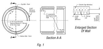
Illustrative Example of
S-Stirrup Support System for 0.01-inch Crack D-load 3000, 102-inch diameter
Pipe Minimum Area Per Support 0.053 square inch, 11 Lines Spaced @ 5 1/8
inches. For other classes and sizes,
see Tables 706.02-2, 3, and 4.
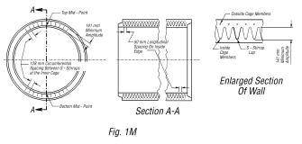
Illustrative Example of
S-Stirrup Support System for 0.3 mm Crack D-Load 140.0, 2550 mm diameter Pipe
Minimum Area per Support 34 mm2, 11 Lines Spaced @ 128 mm. For other classes and sizes, see Tables
706.02-2M, 3M, and 4M.
TABLE 706.02-1 |
|||
|
0.01-inch Crack
D-Load 1000 Ultimate
Strength D-Load 1500 |
|||
|
Internal Diameter of Pipe (in) |
Wall Thickness (in) |
Circular
Reinforcement in Circular Pipe |
|
|
Inner Cage (in2/ft
of pipe) |
Outer Cage (in2/ft
of pipe) |
||
|
Reinforcing
Steel 709.11 or 709.12 Only Concrete
Strength 4000 psi |
|||
|
36 |
4 |
0.09 |
0.07 |
|
42 |
4 1/2 |
0.11 |
0.08 |
|
48 |
5 |
0.13 |
0.09 |
|
54 |
5 1/2 |
0.16 |
0.12 |
|
60 |
6 |
0.19 |
0.14 |
|
66 |
6 1/2 |
0.21 |
0.16 |
|
72 |
7 |
0.23 |
0.17 |
|
78 |
7 1/2 |
0.25 |
0.19 |
|
84 |
8 |
0.29 |
0.21 |
|
90 |
8 |
0.33 |
0.24 |
|
96 |
8 1/2 |
0.37 |
0.26 |
|
Concrete
Strength 5000 psi |
|||
|
102 |
8 1/2 |
0.41 |
0.28 |
|
108 |
9 |
0.47 |
0.3 |
|
All Permitted
Reinforcing Steel Concrete
Strength 5000 psi |
|||
|
114 |
9 1/2 |
0.56 |
0.42 |
|
120 |
10 |
0.61 |
0.46 |
|
126 |
10 1/2 |
0.65 |
0.49 |
|
132 |
11 |
0.7 |
0.52 |
|
144 |
12 |
0.8 |
0.6 |
TABLE 706.02-1M |
|||
|
0.3 mm Crack
D-Load 50.0 Ultimate
Strength D-Load 75.0 |
|||
|
Internal Diameter of Pipe (mm) |
Wall Thickness (mm) |
Circular Reinforcement
in Circular Pipe |
|
|
Inner Cage (cm2/m of pipe) |
Outer Cage (cm2/m of pipe) |
||
|
Reinforcing
Steel 709.11 or 709.12 Only Concrete
Strength 27.6 MPa |
|||
|
900 |
100 |
1.9 |
1.5 |
|
1050 |
113 |
2.3 |
1.7 |
|
1200 |
125 |
2.8 |
1.9 |
|
1350 |
138 |
3.4 |
2.5 |
|
1500 |
150 |
4 |
3 |
|
1650 |
163 |
4.4 |
3.4 |
|
1800 |
175 |
4.9 |
3.6 |
|
1950 |
188 |
5.3 |
4 |
|
2100 |
200 |
6.1 |
4.4 |
|
2250 |
200 |
7 |
5.1 |
|
2400 |
213 |
7.8 |
5.5 |
|
Concrete
Strength 34.5 MPa |
|||
|
2550 |
213 |
8.7 |
5.9 |
|
2700 |
225 |
9.9 |
6.4 |
|
All Permitted
Reinforcing Steel Concrete
Strength 34.5 MPa |
|||
|
2850 |
238 |
11.9 |
8.9 |
|
3000 |
250 |
12.9 |
9.7 |
|
3150 |
263 |
13.8 |
10.4 |
|
3300 |
275 |
14.8 |
11 |
|
3600 |
300 |
16.9 |
12.7 |
4.1.1 In addition, test the pipe designs covered by Tables 706.02-1, 706.02-2, 706.02-3, and 706.02-4 and ASTM C 76 (ASTM C 76M), Tables 2 through 5, and interpolated designs by the three-edge bearing method. When the test load on the pipe reaches 115 percent of the required 0.01-inch (0.3 mm) crack D-load without developing a 0.01-inch (0.3 mm) or larger crack, accept the test specimen for strength. If any test specimen fails to pass this test, but attained the 0.01-inch (0.3 mm) crack, continue the test until the ultimate D-load is reached.
4.1.2 In addition, accept pipe 54 inches (1350 mm) and larger in diameter covered by Tables 706.02-1, 706.02-2, 706.02-3, and 706.02-4, and ASTM C 76 (ASTM C 76M), Tables 2 through 5, and interpolated designs according to Section 12 and the following requirements:
1. When pipe from a plant has been approved by the Laboratory for a specified design and pipe from the same plant has wall and steel area not less than the approved pipe.
2. When it has been established that two or more plants have complied with the above requirements for the class and size under consideration, and the plant under consideration has established compliance with the above requirements for an adjacent size, and the wall and steel area are not less than the pipe tested at the two plants.
6.1.2.1 Provide cement conforming to 701.
6.1.3 Provide aggregates conforming to the quality requirements of 703.02.
6.1.5 Provide steel conforming to 709.08, 709.10, 709.11, or 709.12.
6.2.4 Ensure that no more than two holes are cast, drilled, or otherwise neatly made in the shell of each piece of pipe for the purpose of handling or laying. Ensure that the holes are tapered unless drilled, and before backfilling, fill the tapered holes with portland cement mortar, or secure precast concrete plugs with portland cement mortar. Fill drilled holes with portland cement mortar.
7.1 and 7.3 In addition, perform strength tests using methods described in ASTM C 497 (ASTM C 497M).
10.1 In addition, ensure that pipe designs covered by Tables 706.02-1, 706.02-2, 706.02-3, and 706.02-4 and ASTM C 76 (ASTM C 76M) Tables 2 through 5 have the number of samples selected as shown in the “Minimum Requirements for Sampling Materials” table for each size, class, and production lot (pipe of the same size and class made from the same materials and by the same process and approximately the same production date) for test.
TABLE
706.02-2 |
|
||||||||
|
0.01-inch
Crack D-Load 1350 Ultimate
Strength D-Load 2000 |
|
||||||||
|
Internal Diameter of
Pipe (in) |
Wall Thickness (in) |
Circular
Reinforcement in
Circular Pipe |
S-Stirrups |
|
|||||
|
Minimum
Area Per
Support Element (in2) |
Number of
Lines[1] |
Longitudinal Spacing (in) |
Circumferential Spacing
on Inner
Cage (in) |
Minimum Amplitude[2] of
Stirrups (in) |
|||||
|
Inner
Cage (in2/ft
of pipe) |
Outer
Cage (in2/ft
of pipe) |
||||||||
|
Reinforcing
Steel 709.11 or 709.12 Only Concrete
Strength 4000 psi |
|
||||||||
|
36 |
4 |
0.12 |
0.09 |
|
|
|
|
|
|
|
42 |
4 1/2 |
0.15 |
0.11 |
|
|
|
|
|
|
|
48 |
5 |
0.17 |
0.12 |
|
|
|
|
|
|
|
54 |
5 1/2 |
0.21 |
0.16 |
|
|
|
|
|
|
|
60 |
6 |
0.26 |
0.20 |
|
|
|
|
|
|
|
66 |
6 1/2 |
0.30 |
0.21 |
|
|
|
|
|
|
|
72 |
7 |
0.35 |
0.24 |
|
|
|
|
|
|
|
78 |
7 1/2 |
0.40 |
0.27 |
|
|
|
|
|
|
|
84 |
8 |
0.47 |
0.30 |
|
|
|
|
|
|
|
Concrete
Strength 5000 psi |
|
||||||||
|
90 |
8 |
0.64 |
0.35 |
|
|
|
|
|
|
|
96 |
8 1/2 |
0.80 |
0.40 |
|
|
|
|
|
|
|
102 |
8 1/2 |
0.96 |
0.44 |
|
|
|
|
|
|
|
108 |
9 |
1.07 |
0.47 |
|
|
|
|
|
|
|
TABLE
706.02-2 (continued) |
||||||||
|
All
Permitted Reinforcing Steel Concrete
Strength 5000 psi |
||||||||
|
114 |
9 1/2 |
0.69 |
0.52 |
0.041 |
5 |
2 |
6 1/8 |
6 5/8 |
|
120 |
10 |
0.74 |
0.55 |
0.041 |
5 |
2 |
6 1/2 |
7 1/8 |
|
126 |
10
1/2 |
0.79 |
0.60 |
0.041 |
5 |
2 |
6 7/8 |
7 5/8 |
|
132 |
11 |
0.85 |
0.64 |
0.041 |
5 |
2 |
7 1/4 |
8 1/8 |
|
144 |
12 |
0.97 |
0.73 |
0.041 |
5 |
2 |
8 |
9 1/8 |
|
[1] Number
of lines in the table indicates the number of longitudinal lines required in
each top and bottom portion of the pipe.
The area of each support element in a pipe is two times the
cross-sectional area of the S-stirrups wire used. There shall be an equal number of these lines of S-stirrups on
either side of the mid-point of both the top and bottom of the pipe. See Figure 1. |
||||||||
|
[2] The
amplitude is the overall width of the line of stirrups. |
||||||||
|
TABLE
706.02-2M |
|||||||||
|
0.3
mm Crack D-Load 65.0 Ultimate
Strength D-Load 100.0 |
|
||||||||
|
Internal Diameter of
Pipe (mm) |
Wall Thickness (mm) |
Circular
Reinforcement in
Circular Pipe |
S-Stirrups |
|
|||||
|
Minimum
Area Per
Support Element (mm2) |
Number of
Lines[1] |
Longitudinal Spacing (mm) |
Circumferential Spacing
on Inner
Cage (mm) |
Minimum Amplitude[2] of
Stirrups (mm) |
|||||
|
Inner
Cage (cm2/m
of pipe) |
Outer
Cage (cm2/m
of pipe) |
||||||||
|
Reinforcing
Steel 709.11 or 709.12 Only Concrete
Strength 27.6 MPa |
|
||||||||
|
900 |
100 |
2.5 |
1.9 |
|
|
|
|
|
|
|
1050 |
113 |
3.2 |
2.3 |
|
|
|
|
|
|
|
1200 |
125 |
3.6 |
2.5 |
|
|
|
|
|
|
|
1350 |
138 |
4.4 |
3.4 |
|
|
|
|
|
|
|
1500 |
150 |
5.5 |
4.2 |
|
|
|
|
|
|
|
1650 |
163 |
6.4 |
4.4 |
|
|
|
|
|
|
|
1800 |
175 |
7.4 |
5.1 |
|
|
|
|
|
|
|
1950 |
188 |
8.5 |
5.7 |
|
|
|
|
|
|
|
2100 |
200 |
9.9 |
6.4 |
|
|
|
|
|
|
|
Concrete
Strength 34.5 MPa |
|
||||||||
|
2250 |
200 |
13.5 |
7.4 |
|
|
|
|
|
|
|
2400 |
213 |
16.9 |
8.5 |
|
|
|
|
|
|
|
2550 |
213 |
20.3 |
9.3 |
|
|
|
|
|
|
|
2700 |
225 |
22.6 |
9.9 |
|
|
|
|
|
|
|
TABLE
706.02-2M (CONTINUED) |
||||||||
|
All
Permitted Reinforcing Steel Concrete
Strength 34.5 MPa |
||||||||
|
2850 |
238 |
14.6 |
11.0 |
26 |
5 |
50 |
156 |
168 |
|
3000 |
250 |
15.7 |
11.6 |
26 |
5 |
50 |
165 |
181 |
|
3150 |
263 |
16.7 |
12.7 |
26 |
5 |
50 |
175 |
194 |
|
3300 |
275 |
18.0 |
13.5 |
26 |
5 1 |
50 |
184 |
206 |
|
3600 |
300 |
20.5 |
15.5 |
26 |
5 |
50 |
203 |
232 |
|
[1] Number
of lines in the table indicates the number of longitudinal lines required in
each top and bottom portion of the pipe.
The area of each support element in a pipe is two times the
cross-sectional area of the S-stirrups wire used. There shall be an equal number of these lines of S-stirrups on
either side of the mid-point of both the top and bottom of the pipe. See Figure 1M. |
||||||||
|
[2] The
amplitude is the overall width of the line of stirrups. |
||||||||
|
TABLE
706.02-3 |
|
||||||||
|
0.01-inch
Crack D-Load 2000 Ultimate
Strength D-Load 3000 Concrete
Strength 5000 psi |
|
||||||||
|
Internal Diameter of
Pipe (in) |
Wall Thickness (in) |
Circular
Reinforcement in
Circular Pipe |
S-Stirrups |
|
|||||
|
Minimum
Area Per
Support Element (in2) |
Number of
Lines[1] |
Longitudinal Spacing (in) |
Circumferential
Spacing on Inner
Cage (in) |
Minimum Amplitude[2] of
Stirrups (in) |
|||||
|
Inner
Cage (in2/ft
of pipe) |
Outer
Cage (in2/ft
of pipe) |
||||||||
|
78 |
7
1/2 |
0.69 |
0.52 |
0.029 |
11 |
2 |
4
1/8 |
4
5/8 |
|
|
84 |
8 |
0.74 |
0.56 |
0.029 |
11 |
2 |
4
5/8 |
5
1/8 |
|
|
90 |
8 |
0.85 |
0.63 |
0.031 |
11 |
2 |
4
5/8 |
5
1/8 |
|
|
96 |
8
1/2 |
0.91 |
0.69 |
0.034 |
11 |
2 |
5
1/8 |
5
5/8 |
|
|
102 |
8
1/2 |
1.02 |
0.77 |
0.041 |
12 |
2 |
5
1/8 |
5
5/8 |
|
|
108 |
9 |
1.07 |
0.80 |
0.045 |
11 |
2 |
5
5/8 |
6
1/8 |
|
|
114 |
9
1/2 |
1.02 |
0.77 |
0.048 |
11 |
2 |
6
1/8 |
6
5/8 |
|
|
120 |
10 |
1.10 |
0.82 |
0.051 |
11 |
2 |
6
1/2 |
7
1/8 |
|
|
126 |
10
1/2 |
1.17 |
0.88 |
0.055 |
11 |
2 |
6
7/8 |
7
5/8 |
|
|
132 |
11 |
1.25 |
0.94 |
0.058 |
11 |
2 |
7
1/4 |
8
1/8 |
|
|
144 |
12 |
1.42 |
1.07 |
0.065 |
11 |
2 |
8 |
9
1/8 |
|
|
[1] Refer to Footnote for Table 706.02-2. |
|
||||||||
|
[2] Refer to Footnote for Table 706.02-2. |
|
||||||||
|
TABLE
706.02-3m |
|
||||||||
|
0.3
mm Crack D-Load 100 Ultimate
Strength D-Load 150 Concrete
Strength 34.5 MPa |
|
||||||||
|
Internal Diameter of
Pipe (mm) |
Wall Thickness (mm) |
Circular
Reinforcement in
Circular Pipe |
S-Stirrups |
|
|||||
|
Minimum
Area Per
Support Element (mm2) |
Number of Lines[1] |
Longitudinal Spacing (mm) |
Circumferential
Spacing on Inner
Cage (mm) |
Minimum Amplitude[2] of
Stirrups (mm) |
|||||
|
Inner
Cage (cm2/m
of pipe) |
Outer
Cage (cm2/m
of pipe) |
||||||||
|
1950 |
188 |
14.6 |
11.0 |
19 |
11 |
50 |
105 |
117 |
|
|
2100 |
200 |
15.7 |
11.9 |
19 |
11 |
50 |
117 |
130 |
|
|
2250 |
200 |
18.0 |
13.3 |
20 |
11 |
50 |
117 |
130 |
|
|
2400 |
213 |
19.3 |
14.6 |
22 |
11 |
50 |
130 |
143 |
|
|
2550 |
213 |
21.6 |
16.3 |
26 |
12 |
50 |
130 |
143 |
|
|
2700 |
225 |
22.6 |
16.9 |
29 |
11 |
50 |
143 |
156 |
|
|
2850 |
238 |
21.6 |
16.3 |
31 |
11 |
50 |
156 |
168 |
|
|
3000 |
250 |
22.3 |
17.4 |
33 |
11 |
50 |
165 |
181 |
|
|
3150 |
263 |
24.8 |
18.6 |
35 |
11 |
50 |
175 |
194 |
|
|
3300 |
275 |
26.5 |
19.9 |
37 |
11 |
50 |
184 |
206 |
|
|
3600 |
300 |
30.1 |
22.6 |
42 |
11 |
50 |
203 |
232 |
|
|
[1] Refer to Footnote for Table 706.02-2M. |
|||||||||
|
[2] Refer to Footnote for Table 706.02-2M. |
|||||||||
TABLE
706.02-4 |
|
||||||||
|
0.01-inch
Crack D-Load 3000 Ultimate
Strength D-Load 3750 |
|
||||||||
|
Internal Diameter of
Pipe (in) |
Wall Thickness (in) |
Circular
Reinforcement in
Circular Pipe |
S-Stirrups |
|
|||||
|
Minimum
Area Per
Support Element (in2) |
Number of
Lines[1] |
Longitudinal Spacing (in) |
Circumferential Spacing
on Inner
Cage (in) |
Minimum Amplitude[2] of Stirrups (in) |
|||||
|
Inner
Cage (in2/ft
of pipe) |
Outer
Cage (in2/ft
of pipe) |
||||||||
|
Concrete
Strength 6000 psi |
|
||||||||
|
6 |
1 3/4 |
0.07 |
-- |
|
|
|
|
|
|
|
8 |
1 3/4 |
0.07 |
-- |
|
|
|
|
|
|
|
10 |
1 3/4 |
0.07 |
-- |
|
|
|
|
|
|
|
54 |
5 1/2 |
0.86 |
0.62 |
|
|
|
|
|
|
|
60 |
6 |
0.95 |
0.68 |
|
|
|
|
|
|
|
Concrete
Strength 5000 psi |
|
||||||||
|
54 |
5 1/2 |
0.64 |
0.48 |
0.029 |
15 |
2 |
2 1/8 |
2 5/8 |
|
|
60 |
6 |
0.70 |
0.53 |
0.029 |
14 |
2 |
2 5/8 |
3 1/8 |
|
|
66 |
6 1/2 |
0.79 |
0.59 |
0.029 |
13 |
2 |
3 1/8 |
3 5/8 |
|
|
72 |
7 |
0.87 |
0.66 |
0.029 |
12 |
2 |
3 5/8 |
4 1/8 |
|
|
78 |
7 1/2 |
0.92 |
0.69 |
0.031 |
11 |
2 |
4 1/8 |
4 5/8 |
|
|
84 |
8 |
0.99 |
0.74 |
0.034 |
11 |
2 |
4 5/8 |
5 1/8 |
|
|
90 |
8 |
1.13 |
0.85 |
0.041 |
11 |
2 |
4 5/8 |
5 1/8 |
|
|
TABLE
706.02-4 (CONTINUED) |
||||||||
|
Concrete
Strength 5000 psi |
||||||||
|
96 |
8 1/2 |
1.20 |
0.90 |
0.045 |
11 |
2 |
5 1/8 |
5 5/8 |
|
102 |
8 1/2 |
1.34 |
1.00 |
0.053 |
11 |
2 |
5 1/8 |
5 5/8 |
|
108 |
9 |
1.51 |
1.13 |
0.063 |
11 |
2 |
5 5/8 |
6 1/8 |
|
114 |
9 1/2 |
1.51 |
1.13 |
0.064 |
11 |
2 |
6 1/8 |
6 5/8 |
|
120 |
10 |
1.62 |
1.21 |
0.068 |
11 |
2 |
6 1/2 |
7 1/8 |
|
126 |
10
1/2 |
1.73 |
0.13 |
0.072 |
11 |
2 |
6 7/8 |
7 5/8 |
|
132 |
11 |
1.84 |
0.14 |
0.076 |
11 |
2 |
7 1/4 |
8 1/8 |
|
144 |
12 |
2.09 |
1.57 |
0.085 |
11 |
2 |
8 |
9 1/8 |
|
[1] Refer to Footnote for Table 706.02-2. |
||||||||
|
[2] Refer to Footnote for Table 706.02-2. |
||||||||
|
TABLE
706.02-4M |
|
||||||||
|
0.3
mm Crack D-Load 140.0 Ultimate
Strength D-Load 175.0 |
|
||||||||
|
Internal Diameter of
Pipe mm |
Wall Thickness mm |
Circular
Reinforcement in
Circular Pipe |
S-Stirrups |
|
|||||
|
Minimum
Area Per
Support Element (mm2) |
Number of
Lines[1] |
Longitudinal Spacing (mm) |
Circumferential Spacing
on Inner
Cage (mm) |
Minimum Amplitude[2] of
Stirrups (mm) |
|||||
|
Inner
Cage (cm2/m of pipe) |
Outer
Cage (cm2/m
of pipe) |
||||||||
|
Concrete
Strength 41.4 MPa |
|
||||||||
|
150 |
44 |
1.5 |
-- |
|
|
|
|
|
|
|
200 |
44 |
1.5 |
-- |
|
|
|
|
|
|
|
250 |
44 |
1.5 |
-- |
|
|
|
|
|
|
|
1350 |
138 |
18.2 |
13.1 |
|
|
|
|
|
|
|
1500 |
150 |
20.1 |
14.4 |
|
|
|
|
|
|
|
Concrete Strength 34.5 MPa |
|
||||||||
|
1350 |
138 |
13.5 |
10.2 |
19 |
15 |
50 |
54 |
67 |
|
|
1500 |
150 |
14.8 |
11.2 |
19 |
14 |
50 |
37 |
79 |
|
|
1650 |
163 |
16.7 |
12.5 |
19 |
13 |
50 |
79 |
92 |
|
|
1800 |
175 |
18.4 |
14.0 |
19 |
12 |
50 |
92 |
105 |
|
|
1950 |
188 |
19.5 |
14.6 |
20 |
11 |
50 |
105 |
117 |
|
|
2100 |
200 |
21.0 |
15.7 |
22 |
11 |
50 |
117 |
130 |
|
|
2250 |
200 |
23.9 |
18.0 |
26 |
11 |
50 |
117 |
130 |
|
|
TABLE
706.02-4M (CONTINUED) |
||||||||
|
Concrete Strength 34.5 MPa |
||||||||
|
2400 |
213 |
25.4 |
19.1 |
29 |
11 |
50 |
130 |
143 |
|
2550 |
213 |
28.4 |
21.2 |
34 |
11 |
50 |
130 |
143 |
|
2700 |
225 |
32.0 |
23.9 |
41 |
11 |
50 |
143 |
156 |
|
2850 |
238 |
32.0 |
23.9 |
41 |
11 |
50 |
156 |
168 |
|
3000 |
250 |
34.3 |
25.6 |
44 |
11 |
50 |
165 |
181 |
|
3150 |
263 |
36.6 |
27.5 |
46 |
11 |
50 |
175 |
194 |
|
3200 |
275 |
38.9 |
29.2 |
49 |
11 |
50 |
184 |
206 |
|
3600 |
300 |
44.2 |
33.2 |
55 |
11 |
50 |
203 |
232 |
|
[1] Refer to Footnote for Table 706.02-2M. |
||||||||
|
[2] Refer to Footnote for Table 706.02-2M. |
||||||||
11.1 Perform
compression tests on cores conforming to ASTM C 497 (ASTM C 497M).
11.3 Does not apply.
12 Perform
inspection at the project site. Obtain
random samples from material delivered to the project site or at other
locations designated by the Laboratory.
16 Does not apply.
17 In addition,
after the capital letter “D,” designate the D-load, the design wall thickness
in millimeters (inches expressed as a decimal). Ensure that pipe with S-stirrups have the symbol “S”. Ensure that pipe requiring axis orientation
without lift holes (i.e., stirrup pipe, quadrant reinforced pipe, elliptically
reinforced pipe) has the centerline of the crown of the pipe marked inside and
outside with the symbol “TB”. Mark pipe
with quadrant steel with the symbol “Q”.
Mark pipe with elliptical reinforcement with the symbol “E”. Mark pipe with deformed wire reinforcement
required in the design with the symbol “DF”.
706.03 Reinforced Concrete Pipe, Epoxy Coated. Provide Type A reinforced
concrete epoxy coated pipe conforming to 706.02 and Type B conforming to
706.04, with the following modification:
In the plant, prepare the interior barrel and joint surface
areas of the concrete pipe to remove all forms of oil, laitance, and other
deleterious materials and then line them with a high-build, polyamide-cured,
two-component coal tar epoxy coating, Military Specification
DOD-P-23236A (SH). Spray the lining
compound to obtain a continuous and relatively uniform and smooth lining with a
minimum dry film thickness of 0.03 inch (760 mm). Ensure that all coated pipe are free of surface irregularities
such as air bubbles, delamination, lumping, sagging, blistering, pinholing, or
porosity, in the coating film.
706.04 Reinforced Concrete Elliptical Culvert,
Storm Drain, and Sewer Pipe. Provide reinforced concrete
elliptical culvert, storm drain, and sewer pipe conforming to ASTM C 507 (ASTM
C 507M), with the following modifications:
4.1 Delete Class HE-A. Table 706.04-1 includes additional design requirements.
5.1 All materials, processes of manufacture, and finished pipe are subject to inspection and approval by the Department. When directed by the Laboratory, the manufacturer will cut holes in sections of the finished pipe for inspection.
6.2.1 Provide cement conforming to 701, except 701.07.
6.3 Provide aggregates conforming to the quality requirements of 703.02.
6.5 Provide steel conforming 709.08, 709.10, 709.11, or 709.12.
7.2 In addition, manufacture horizontal elliptical pipe HE-II and HE-III using the design requirements of Table 706.04-1.
8.1 In addition, ensure that pipe made in accordance with 706.04-1 has three lines of reinforcement of elliptical shape. Place the outer and inner lines of reinforcement so that the nominal protective covering of the concrete over the reinforcement in the barrel of the pipe is 1 inch (25 mm) subject to the variations permitted in Section 12.5. Ensure that the third or middle line is in contact with and fastened securely to the inner line at the vertical axis of the pipe both top and bottom and to the outer line at the horizontal axis on both sides. Ensure that the length of the middle line is the average of the length of the inner and outer line. Ensure that the middle line is of an elliptical shape and runs smoothly between the specified points of contact with the inner and outer lines.
10 Ensure that no more than two holes are cast, drilled, or otherwise neatly made in the shell of each piece of pipe for the purpose of handling or laying. Taper the holes unless drilled, and before backfilling, fill the tapered holes with portland cement mortar, or secure the precast concrete plugs with portland cement mortar. Fill the drilled holes with portland cement mortar.
11.2 Select the specified number of pipe, as noted in the “Minimum Requirements for Sampling Materials” table, for the purpose of test at the plant and at random from the lot to be shipped or at the project site from the pipe delivered and that are pipe that would not otherwise be rejected under these Specifications. Test pipe according to Section 5.1.1 except the Laboratory may accept pipe 54 inches (1350 mm) and larger in diameter according to Section 5.1.2 and the following requirements:
1. When pipe from a plant has been approved by the Laboratory for a specified design, pipe from the same plant with wall and steel area not less than the approved pipe may be approved by means of tests on cores verifying absorption, strength, wall, and steel area.
2. When it has been established that two or more plants have complied with the above requirements for the class and size under consideration and the plant under consideration has established compliance with the above requirements for an adjacent size, and the wall and steel area are not less than the pipe tested at the two plants.
11.3.1 Ensure that the load to produce a 0.01-inch (0.3 mm) crack and the ultimate load as determined by ASTM C 497 (ASTM C 497M) three-edge bearing method, is not less than shown in Tables 1, 2, and 706.04-1. The ultimate strength test may be waived when the test load on the pipe reaches 115 percent of the required 0.01-inch (0.3 mm) crack D-load without developing a 0.01-inch (0.3 mm) or larger crack.
11.4 Perform compression tests for satisfying the minimum specified concrete strength requirement from cores drilled from the wall of the pipe. Ensure that the diameter of the core is such that the capped height to diameter or L/D ratio lies between one and two. Ensure that the cores are secured, prepared for testing, and tested by methods prescribed in the appropriate sections of ASTM C 497 (ASTM C 497M). Ensure that the compressive strength of each core tested is equal to or greater than the design strength of the concrete. If a core does not meet the required strength, test another core from the same pipe. If this core does not meet the required strength, the Department may reject the pipe. Make additional tests on other pipe to determine the acceptability of the lot. When the cores cut from a section of pipe successfully meet the strength test requirement, ensure that the core holes are plugged and sealed by the manufacturer in a manner such that the pipe section will meet all of the test requirements of these Specifications.
11.9 Does not apply.
11.10 Does not apply.
14 Perform inspection at the project site. Obtain random samples from material delivered to the project site or at other locations designated by the laboratory.
16 In addition, place the plant location on each pipe, and for pipe manufactured to design requirements of 706.04-1 place the letter “A” after the pipe class. Ensure that the markings are legible and indented in the pipe section or painted on with waterproof paint.
Table 706.04-1 Design Requirements for Horizontal Elliptical Pipe |
||||
|
Equivalent Round Size (in) |
Rise (in) ´ Span (in) |
Minimum Wall Thickness (in) |
Minimum Reinforcement (in2/ft) |
|
|
HE-II |
HE-III |
|||
|
D-Loads |
||||
|
0.01=1000 |
0.01 = 1350 |
|||
|
Utl. = 1500 |
Utl. = 2000 |
|||
|
78 |
63 ´ 98 |
8 |
3 lines totaling 0.87 |
3 lines totaling 1.23 |
|
84 |
68 ´ 106 |
8 1/2 |
3 lines totaling 0.97 |
3 lines totaling 1.33 |
|
90 |
72 ´ 113 |
9 |
3 lines totaling 1.03 |
3 lines totaling 1.43 |
|
96 |
77 ´ 121 |
9 1/2 |
3 lines totaling 1.13 |
3 lines totaling 1.54 |
|
102 |
82 ´ 128 |
9 3/4 |
3 lines totaling 1.23 |
3 lines totaling 1.70 |
|
108 |
87 ´ 136 |
10 |
3 lines totaling 1.43 |
3 lines totaling 1.85 |
|
The
test load in lb/ft equals D-load x nominal inside span in feet. Concrete strength=5000 psi. |
||||
|
Table 706.04-1M
Design Requirements for Horizontal Elliptical Pipe |
||||
|
Equivalent Round Size (mm) |
Rise (mm) ´ Span (mm) |
Minimum Wall Thickness (mm) |
Minimum Reinforcement (cm2/m) |
|
|
HE-II |
HE-III |
|||
|
D-Loads |
||||
|
0.03 = 50.0 |
0.03=65.0 |
|||
|
Utl. = 75.0 |
Utl.=100.0 |
|||
|
1950 |
1585 ´ 2495 |
200 |
3 lines totaling 18.4 |
3 lines totaling 26.0 |
|
2100 |
1705 ´ 2690 |
213 |
3 lines totaling 20.5 |
3 lines totaling 28.2 |
|
2250 |
1830 ´ 2880 |
225 |
3 lines totaling 21.8 |
3 lines totaling 30.3 |
|
2400 |
1950 ´ 3070 |
238 |
3 lines totaling 23.9 |
3 lines totaling 32.6 |
|
2550 |
2075 ´ 3265 |
244 |
3 lines totaling 26.0 |
3 lines totaling 36.0 |
|
2700 |
2195 ´ 3455 |
250 |
3 lines totaling 30.3 |
3 lines totaling 39.2 |
|
The
test load in kN/m equals D-load x nominal inside span in mm. Concrete strength=34.5 MPa. |
||||
706.05 Precast Reinforced Concrete Box Sections. Provide precast reinforced concrete box section conforming to ASTM C 1433 (ASTM C 1433M), with the following modifications:
Ensure that manufacturers of precast concrete members are certified by the Laboratory according to Supplement 1073.
6.2.1 Provide cement conforming to 701, except 701.07.
6.3 Provide aggregates conforming to the quality requirements of 703.02.
6.5 Provide steel conforming to 709.10 or 709.12. Ensure that the longitudinal distribution reinforcement for box sections with less than 2 feet (0.6 m) of cover are subject to highway loadings in 709.01 conforming to ASTM A 615, Grade 60 (ASTM A 615M, Grade 400).
7.1 Only designs from Table 2 with the following sizes are permitted. The box sizes, span by rise, are 8 ´ 4, 5, 6, 7; 10 ´ 5, 6, 7, 8, 9; and 12 ´ 4, 6, 8, 10 feet (2400 ´ 1200, 1500, 1800, 2100; 3000 ´ 1500, 1800, 2100, 2400, 2700; and 3600 ´ 1200, 1800, 2400, 3000 mm).
9.1 Provide hardened concrete that contains a minimum of 4 percent entrained air for wet-cast sections with spans less than 14 feet (4200 mm) and for all sections with spans 14 feet (4200 mm) and greater.
9.4 Lift holes are not permitted. Use handling devices that do not require a hole through the box.
10.1 Verify concrete
strength using cylinders. Do not ship
items before the design strength of the concrete is reached.
11.5 A minimum cover of 1/2 inch (13 mm) over both circumferential and longitudinal reinforcement is required at the mating surfaces of joints.
15 In addition, mark the identification of the plant on each box section. For box sections 14 feet (4200 mm) or greater, mark the reinforcing steel areas for the section on each box section. Place the manufacturers’ name and required product information on the inside of the box section within the top one-half of the culvert.
706.051 Precast Reinforced Concrete Three-Sided Flat Topped Culverts. Provide precast concrete three-sided flat topped culverts according to ASTM C 1504, with the following modifications:
Provide flat deck culvert structures with a minimum clear span (measured normal to the structure at the bottom of the haunch) of 14 feet (4200 mm) and a minimum opening rise (measured from bottom of leg to bottom of deck at the centerline of the structure) of 4 feet (1200 mm); and a maximum clear span of 34 feet (10,200 mm) and maximum opening rising of 10 feet (3000 mm). Ensure that the minimum wall and deck thicknesses shall be 10 inches (250 mm) and 12 inches (300 mm) respectively, measured under the haunch normal to the structure and at the centerline of the span measured perpendicular to the structure.
Ensure that manufacturers of precast concrete members are certified by the Laboratory according to Supplement 1073.
5 Ensure that the manufacturer submits shop drawings and design calculations for review and written approval before production as per Item 603. Submit a minimum of seven copies of the drawings. Allow a minimum of four weeks for approval. Ensure that the shop drawings include the following:
1. All structural design and loading information.
2. All material specifications.
3. All plan view.
4. All elevation view.
5. All headwall and wingwall attachment requirements.
6. All dimensions.
7. All maintenance of traffic phases.
8. All section sizes.
9. All design handling strength.
The manufacturer may modify an approved shop drawing and resubmit for approval to the Department.
Ensure that the shop drawings also include the following special information as required:
1. For top mounted guardrail, show the guardrail plate and bolt locations in the plan view. Ensure that holes are a minimum of 6 inches (150 mm) from a joint.
2. For side mounted guardrail, show additional reinforcing details as per the plan details.
6.3 Provide aggregates conforming to the quality requirements of 703.02.
6.4 Use chemical admixtures conforming to 705.12. Use a corrosion inhibitor unless epoxy coated reinforcing steel is used. An approved list of corrosion inhibiting admixtures is on file at the Laboratory. Manufacturers should recognize that the corrosion inhibitors and admixtures may have an effect on strength, entrained air content, workability, etc. of their concrete mixes. The manufacturers choice of one of these corrosion inhibitors does not alleviate meeting all design requirements of this structure.
6.4.1 Provide air-entraining admixture conforming to 705.10.
6.5 Provide reinforcement consists of welded wire fabric conforming to 709.10 or 709.12, or deformed billet steel bars conforming to CMS 709.01, Grade 60 (Grade 420). Provide epoxy coated reinforcement conforming to 709.00 or 709.14. In lieu of epoxy coated reinforcement, use a corrosion inhibiting concrete admixture. Reinforcement from a precast structure into a cast-in-place structure, which does not contain a corrosion inhibitor admixture, will be epoxy coated conforming to 709.00 or 709.14.
7.1 Ensure that all designs for concrete compressive strengths greater than 5000 pounds per square inch (35 MPa) include, with the shop drawings, the mix design and a history of successful use of the mix design.
Where circumferential (main) reinforcement is composed of bars, check crack control criteria using the following: Z = 150 inside face (interior surface) and Z = 130 outside face (exterior surface).
7.2 Ensure that the concrete cover dimension over reinforcement is a minimum of 2 inches (50 mm) in the slab and in the exterior of the leg. Ensure that the interior of the leg reinforcement cover tapers from 1 inch (25 mm) at the bottom of the leg to 2 inches (50 mm) at the bottom of the haunch.
Ensure that the ends of longitudinal reinforcement have a minimum cover of 1/2 inch (13 mm), and spacers used to position the reinforcement are plastic or epoxy coated steel regardless of whether a corrosion inhibiting admixture is used.
8 Ensure that the top slab is produced with a keyway joint. The keyway provides a void volume equivalent to that of 12 inches (300 mm) prestressed beam as per Standard Construction Drawing PSBD-1-93. Ensure that the joint in the leg sections is designed to produce a shear key or inter-locking joint. Ensure that non-adjoining outside legs are flat. Sandblast the joint surfaces to the satisfaction of the Department, or a 2000 pounds per square inch (14 MPa) water blast no more than 14 days prior to shipping. Ensure that the culvert is designed such that the sections when laid together will make a continuous line with a smooth interior free of appreciable irregularities, all compatible with the permissible variations of Section 11.
9 Application of membrane waterproofing at any location other than the final location shown on the plans is prohibited.
9.1 Ensure that the aggregate, cement, and water are manufactured in conformance with 499.06, 499.07, and 499.09.
Ensure that the temperature requirements of 511.08 and 511.15 are met.
Ensure that the proportion of portland cement is not less than 564 pounds per cubic yard (335 kg/m3) of concrete.
If used, add the corrosion inhibitor as an aqueous solution. Consider the water in the solution as mixing water for the purpose of determining the w/c ratio of concrete.
9.2 Cure the three-sided sections in the forms for the length of time required to obtain the specified minimum design handling strength as defined in the shop drawings. Test a cylinder to check each section’s design handling strength. Repeat this test as often as needed. Only one cylinder passing will ensure that the design handling strength has been met. If the shop drawing shows no design handling strengths, then the minimum handling strength is assumed to be 100 percent of the design strength. Ensure that the curing then continues either in or out of the forms until the specified minimum design strength is met.
9.2.1 Steam curing is an accelerated cure by low pressure steam or radiant heat within a suitable insulated enclosure to contain the live steam or heat. The initial application of the steam or heat is from two to four hours after the final placement of concrete to allow the initial set to take place. If retarders are used, increase the waiting period to 4 to 6 hours. As an alternative, determine the actual time of initial set according to ASTM C 403. Do not start curing until the actual time to initial set has elapsed.
During the waiting period, ensure that the temperature within the curing enclosure is not less than 50 °F (10 °C).
During the initial application of live steam or radiant heat, ensure that the ambient temperature within the curing enclosure increases at an average rate not exceeding 40 °F (22 °C) per hour until the curing temperature is reached.
Ensure that the maximum curing temperature does not exceed 150 °F (65 °C). Hold the design temperature until the concrete has reached the desired design strength. Do not direct the application of live steam on the concrete forms so as to cause localized high temperatures.
9.2.2 Provide water curing conforming to 511.15 and 511.17, Method A.
9.2.3 Provide membrane curing conforming to 511.16, Method B.
9.3 Ensure that all forms are in place until the design handling strength is met.
9.4 Holes for handling or setting are not permitted. Do not move members before the design handling strength of the concrete is reached, or shipped before the design strength of the concrete is reached. Ensure that the manufacturers have equipment necessary to handle and transport the pieces without damaging them.
10 Ensure that the hardened concrete contains a minimum of 4 percent entrained air.
10.2.1 Provide cylinders 6 ´ 12 inch (150 ´ 300 mm).
Keep the cylinders and matching culvert section together to guarantee the cylinders are matched with the corresponding culvert section; or, upon agreement by the Department, keep the cylinders at a location that will provide the same environment as the culvert sections.
10.2.2 For each section of the culvert, produce and mark at least four cylinders so that they are identifiable with the matching culvert section.
10.2.3 Conform to Supplement 1073 for acceptance.
10.2.3.1 Ensure that cylinder strengths conform to Supplement 1073.
10.3.3.2 Deleted.
10.3.3.3 Deleted.
10.4 Plug the core holes by using a concrete that is the same as that used in the section and cured in according to Section 9.2, or by a non-shrink grout that exceeds the concrete design strength.
11 The design in the plan reflects the external top slab elevation of the structure. If the structure supplied has a deck thicker than the plan design, eliminate the difference between the design top slab elevation and the supplied top slab elevation by a reducing the leg length. The Department may approve alternate methods to eliminate the difference between the design top slab elevation and the supplied top slab elevation. The Department will not approve a change in the top slab elevation from that shown on the plans.
The clear span shown is the minimum for the structure. The manufacturer may provide a clear span greater than that shown. Base the exact footer locations for both the elevation and offset on the manufacturer’s shop drawings. Ensure that these footer locations are such that the centerline of the leg at the bottom of the haunch matches the centerline of the footer.
All changes to the project resulting from the manufacturer’s dimensional changes in the structure are at no charge to the Department.
Ensure that the sections are free of fractures spalls and chips. Ensure that all surfaces have a smooth and regular finish being defined as a 1/4-inch variation within 4 feet (6 mm variation within 1.2 m).
11.1 Ensure that the slab and walls are perpendicular with a diagonal difference of not more than 0.5 percent.
Ensure that the length of each section is within 1/2 inch (13 mm) of the design length. Consider the length is the average of the length measured at each side and at the middle of the three-sided section.
11.4 Ensure that the maximum variation in the position of the reinforcement is 3/8 inch (9 mm), except that the cover over the reinforcement for the external surface of the top slab is not less than 2 inches (50 mm). The above tolerances or cover requirements do not apply to mating surfaces at the joint.
11.5 Resubmit any change in reinforcement from the shop drawings for approval.
12 Make repairs according to the Department’s requirements. The Department will not make additional payments for culvert repairs. Repairs are acceptable if, in the opinion of the Department, the repairs are sound, properly finished, and cured.
13 Perform inspection at the project site. Deliver only certified precast concrete components conforming to Supplement 1073.
14 Form seams and slight surface irregularities that are expected from a wood panel forming system will not be cause for rejection. In addition, hairline cracks less than 0.01 inch (0.25 mm) are not cause for rejection.
15.1 Ensure that the location of the product marking is on the interior of the three-sided section 1 foot (300 mm) below the leg haunch.
Add the product marking upon removal of the forms.
The manufacturer may be required to repeat the product markings before the project is final.
706.052 Precast Reinforced Concrete Arch Sections. Provide precast reinforced concrete arch sections conforming to ASTM C 1504, with the following modifications:
This item shall consist of manufacturing precast reinforced concrete arch sections for culverts.
Ensure that manufacturers of precast concrete members are certified by the Laboratory according to Supplement 1073.
5 Ensure the manufacturer submits shop drawings and design calculations for review and written approval before production as per Item 603. Submit a minimum of seven copies of the drawings. Allow a minimum of 4 weeks for approval. Ensure the shop drawings include the following:
1. All structural design and loading information.
2. All material specifications.
3. All plan view.
4. All elevation view.
5. All headwall and wingwall attachment requirements.
6. All dimensions.
7. All maintenance of traffic phases.
8. All section sizes.
9. All design handling strength.
The manufacturer may modify an approved shop drawing and resubmit for approval to the Department.
Ensure that the shop drawings also include the following special information as required:
1. For top mounted guardrail, the guardrail plate and bolt locations are shown in the plan view. Holes shall be a minimum of 6 inches (150 mm) from a joint.
2. For side mounted guardrail, additional reinforcing details are shown as per the plan details.
6.3 Provide aggregates conforming to the quality requirements of 703.02.
6.4 Use chemical admixtures conforming to 705.12. Use a corrosion inhibitor unless epoxy coated reinforcing steel is used. An approved list of corrosion inhibiting admixtures is on file at the Laboratory. Manufacturers should recognize that the corrosion inhibitors and admixtures may have an effect on strength, entrained air content, workability, etc. of their concrete mixes. The manufacturers choice of one of these corrosion inhibitors does not alleviate meeting all design requirements of this structure.
6.4.1 Provide air-entraining admixture conforming to 705.10.
6.5 Provide reinforcement consists of welded wire fabric conforming to 709.10 or 709.12, or deformed billet steel bars conforming to CMS 709.01, Grade 60 (Grade 420). Provide epoxy-coated reinforcement conforming to 709.00 or 709.14. Instead of epoxy coated reinforcement, use a corrosion inhibiting concrete admixture. Reinforcement from the precast structure into a cast-in-place structure, which does not contain a corrosion inhibitor admixture, will be epoxy coated conforming to 709.00 or 709.14.
7.1 Ensure that concrete compressive strength are greater than 4000 pounds per square inch (28 MPa).
7.2 Ensure
that the concrete cover dimension over the
outside circumferential reinforcement is a minimum of 2 inches (50 mm). Ensure that the concrete cover dimension
over the inside circumferential reinforcement is a minimum of 1 1/2 inches (38
mm). The clear distance of the end
circumferential wires shall not be less than 1 inch (25 mm) nor more than 2
inches (50 mm) from the ends of the sections.
Reinforcement shall be assembled utilizing single or multiple layers of
welded wire fabric (three-layer maximum), or utilizing a single layer of
deformed billet-steel bars. The welded
wire fabric shall be composed of circumferential and longitudinal wires and
shall contain sufficient longitudinal wires extending through the section to
maintain the shape and position of reinforcement. Longitudinal distribution reinforcement may be welded wire fabric
or deformed billet-steel bars. The ends
of the longitudinal distribution reinforcement shall be not more than 3 inches
(75 mm) from the ends of the sections.
The outside and inside circumferential
reinforcing steel for the corners of the culvert shall be bent to such an angle
that it is approximately equal to the configuration of the culverts outside
corner.
7.3 Tension splices in the circumferential reinforcement
shall not be made. For splices other
than tension splices, the overlap shall be a minimum of 12 inches (300 mm) for
welded wire fabric or deformed billet steel bars. The spacing center-to-center of the circumferential wires in a
wire fabric sheet shall be not less than 2 inches (50 mm) or more than 4 inches
(100 mm). For the wire fabric, the
spacing center-to-center of the longitudinal wire shall not be more than 8
inches (200 mm). The spacing
center-to-center of the longitudinal distribution steel for either line of
reinforcing in the top slab shall be not more than 16 inches (410 mm).
8.1 Ensure the sections are produced with
butt ends. The ends of the sections
shall be such that when the sections are laid together they will make a
continuous line of sections with a smooth interior free of appreciable
irregularities, all compatible with the permissible variations in these
Specifications. Provide a chamfer on
the outside surface at the sections joint to form a void for a 7/8 ´ 1
3/8-inch (24 ´
34 mm) flexible plastic gasket 706.14.
9 Application of membrane waterproofing on the arch section at any location other than the final location shown on the plans is prohibited.
9.1 Ensure that the aggregate, cement, and water are manufactured according to 499.06, 499.07, and 499.09.
Ensure that the temperature requirements of 511.08 and 511.15 are met.
Ensure that the proportion of portland cement is not less than 564 pounds per cubic yard (335 kg/m3) of concrete.
If used, add the corrosion inhibitor as an aqueous solution. Consider the water in the solution as mixing water for the purpose of determining the water-cement ratio of concrete.
9.2 Cure the arch sections in the forms for the length of time required to obtain the specified minimum design handling strength as defined in the shop drawings. Test a cylinder to check each section’s design handling strength. Repeat this test as often as needed. Only one cylinder passing will ensure that the design handling strength has been met. If the shop drawing shows no design handling strengths, then the minimum handling strength is assumed to be 100 percent of the design strength. Ensure that the curing then continues either in or out of the forms until the specified minimum design strength is met.
9.2.1 Steam curing is an accelerated cure by low pressure steam or radiant heat within a suitable insulated enclosure to contain the live steam or heat. The initial application of the steam or heat is from 2 to 4 hours after the final placement of concrete to allow the initial set to take place. If retarders are used, increase the waiting period to 4 to 6 hours. As an alternative, determine the actual time of initial set according to ASTM C 403. Do not start curing until the actual time to initial set has elapsed.
During the waiting period, ensure that the temperature within the curing enclosure is not less than 50 °F (10 °C).
During the initial application of live steam or radiant heat, ensure that the ambient temperature within the curing enclosure increases at an average rate not exceeding 40 °F (22 °C) per hour until the curing temperature is reached.
Ensure that the maximum curing temperature does not exceed 150 °F (65 °C). Hold the design temperature until the concrete has reached the desired design strength. Do not direct the application of live steam on the concrete forms so as to cause localized high temperatures.
9.2.2 Provide water curing conforming to 511.15 and 511.17, Method A.
9.2.3 Deleted.
9.3 Ensure that all forms are in place until the design handling strength is met.
Holes for handling or setting are not permitted. Do not move members before the design handling strength of the concrete is reached, or shipped before the design strength of the concrete is reached. Ensure that the manufacturers have equipment necessary to handle and transport the pieces without damaging them.
10 Ensure that the hardened concrete contains a minimum of 4 percent entrained air.
10.2.1 Provide cylinders 6 ´ 12 inches (150 ´ 300 mm).
Keep the cylinders and matching culvert section together to guarantee the cylinders are matched with the corresponding culvert section; or, upon agreement by the Department, keep the cylinders at a location that will provide the same environment as the culvert sections.
10.2.2 For each section of the culvert, produce and mark at least four cylinders so that they are identifiable with the matching culvert section.
10.2.3 Conform to Supplement 1073 for acceptance.
10.2.3.1 Ensure that cylinder strengths conform to Supplement 1073.
10.4 Plug the core holes by using a concrete that is the same as that used in the section and cured according to Section 9.2, or by a non-shrink grout that exceeds the concrete design strength.
11.0 The under-run in length of a section shall not be more than 1/2 inch (13 mm).
All changes to the project resulting from the manufacturer’s dimensional changes in the structure are at no charge to the Department.
Ensure that the sections are free of fractures spalls and chips. Ensure that all surfaces have a smooth and regular finish being defined as a 1/4 inch variation within 4 feet (6 mm variation within 1.2 m).
11.1 The internal dimensions shall vary not more than 1 percent from the design dimensions or more than 38 mm (1 1/2 inches), whichever is less. The haunch dimensions shall vary not more than 19 mm (3/4 inch) from the design dimension.
11.4 Ensure that the maximum variation in the position of the reinforcement is 3/8 inch (9 mm), except that the cover over the reinforcement for the external surface of the top slab is not less than 2 inches (50 mm). The above tolerances or cover requirements do not apply to mating surfaces at the joint.
11.5 Resubmit any change in reinforcement from the shop drawings for approval.
12.0 Make repairs according to the Department’s requirements. The Department will not make additional payments for culvert repairs. Repairs are acceptable if, in the opinion of the Department, the repairs are sound, properly finished, and cured.
13.0 Perform inspection at the project site. Deliver only certified precast concrete components conforming to Supplement 1073.
14.0 Form seams and slight surface irregularities that are expected from a wood panel forming system will not be cause for rejection. In addition, hairline cracks less than 0.01 inch (0.25 mm) will not be cause for rejection.
15.1 Ensure that the location of the product marking is on the interior of the arch section 1 foot (300 mm) below the leg haunch.
Add the product marking upon removal of the forms.
The manufacturer may be required to repeat the product markings before the project is final.
706.06 Perforated Concrete Pipe. Provide perforated concrete pipe conforming to ASTM C 444 (ASTM C 444M), and 706.01 or 706.02.
706.07 Concrete Drain Tile. Provide extra-quality concrete drain tile conforming to ASTM C 412 (ASTM C 412M), with the following modifications:
4.0 This specification covers extra-quality concrete drain tile only.
5.1.3 Does not apply.
6.2.1 Provide cement conforming to 701, except 701.07.
6.3 Provide aggregate conforming to the quality requirements of 703.02.
8.1 Perform inspection at the project site. Obtain random samples from material delivered to the project site or at other locations designated by the Laboratory.
Testing. Ensure that the manufacturer furnishes all facilities and personnel to carry out the tests.
706.08 Vitrified Clay Pipe. Provide vitrified clay pipe conforming to ASTM C 700, with the following modifications:
14.0 Perform all tests except hydrostatic according to ASTM C 301.
15.0 Perform inspection at the project site. Obtain random samples from material delivered to the project site or at other locations designated by the Laboratory.
706.09 Clay Drain Tile. Provide extra-quality clay drain tile conforming to ASTM C 4, with the following modifications:
6.1 Perform inspection at the project site. Obtain random samples from material delivered to the project site or at other locations designated by the Laboratory.
11, 12, and 13 Ensure that the manufacturer furnishes all facilities and personnel to carry out the tests.
706.10 Bituminous Pipe Joint Filler. Provide cold applied, mineral filled, joint sealing compound for joints of bell and spigot, or tongue and groove sewer; or drain pipe conforming to the following:
A. Composition. Provide a steam-refined petroleum asphalt or a refined coal tar, dissolved in a suitable solvent, and containing an appropriate stiffener.
B. General Requirement. Provide a bituminous plastic cement that has a smooth, uniform mixture, not thickened or livered, and that shows a separation easily overcome by stirring. Ensure that the material is of such consistency and properties that it is readily applied with a trowel, a putty knife, or with a caulking gun without pulling or drawing. Provide a material that when applied to metal, concrete, or vitrified clay surfaces, exhibits good adhesive and cohesive properties and has only slight shrinkage after curing. Provide a material that is not damaged by exposure to below freezing temperatures.
C. Detail Requirements. Provide materials conforming to the following requirements:
|
1. |
When applied in a layer 1/16 to
1/8-inch (1.6 to 3.2 mm) thick on a tinned metal panel and cured at room
temperature for 24 hours, the bituminous plastic cement shall set to a tough,
plastic coating, free from blisters. |
||
|
|
|
Minimum |
Maximum |
|
2. |
Grease Cone Penetration (unworked, 150 grams, 25 °C, 5 sec, ASTM D 217, mm/10 |
175 |
250 |
|
3. |
Weight, kg/L |
1.17 |
-- |
|
4. |
Non-volatile, 10 g, 105 to 110 °C, |
75 |
-- |
|
5. |
Ash, by ignition, % |
25 |
45 |
706.11 Resilient and Flexible Gasket Joints. Provide resilient and flexible gasket joints for concrete pipe conforming to ASTM C 443 (ASTM C 443M).
706.12 Resilient and Flexible Joints. Provide resilient and flexible joints for vitrified clay pipe conforming to ASTM C 425.
706.13 Precast Reinforced Concrete Manhole Riser Sections, Catch Basins and Inlet Tops, and Temporary Barriers. Provide precast reinforced concrete manhole riser sections, catch basins and inlet tops, and temporary barriers conforming to ASTM C 478 (ASTM C 478M), with the following modifications:
1.1 Provide precast catch basin tops where permitted by the plans.
5.0 Perform compression tests for satisfying the minimum specified concrete strength requirements from cores not less than 3 1/2 inches (90 mm) in diameter drilled from the wall of the risers, cones, tops, or barriers. Obtain cores prepared for testing, and tested by the appropriate methods of ASTM C 497 (ASTM C 497M). In addition, ensure that all concrete compression tests made on cores are drilled from precast sections. Provide precast catch basins, inlet tops, and temporary barriers that have 6 ± 2 percent air in the hardened concrete.
Absorption tests do not apply.
Retests do not apply.
4.1.2.1 Provide cement conforming to 701, except 701.07.
4.1.3 Provide aggregate conforming to the quality requirements of 703.02.
4.1.5 Provide epoxy coated steel according to 709.00, and that meet 709.01, 709.08, 709.10, 709.11, or 709.12; ensure that the top bars are epoxy coated according to 709.00. Provide precast catch basin and inlet tops conforming to 709.00.
7.0 In addition, ensure that not more than two holes are cast, drilled, or otherwise neatly made in the shell of each piece of each riser section for the purpose of handling or laying. Taper the holes unless drilled, and before backfilling fill the tapered holes with portland cement mortar or secure the concrete plugs with portland cement mortar. Fill drilled holes with portland cement mortar.
10.0 Perform inspection at the project site. Deliver only certified precast concrete components conforming to Supplement 1073.
11.0 In addition, mark the plant location on each manhole top or barrier section.
706.14 Flexible Plastic Gaskets. Provide flexible plastic gaskets for concrete pipe conforming to AASHTO M 198, Type B, with the following modification:
4.3 Flash point and fire point are waived.
706.15 Precast Reinforced Concrete Outlets. Provide precast reinforced concrete outlets composed of cement conforming to 701, except 701.07. Provide aggregate conforming to the quality requirements of 703.02. Provide epoxy coated steel reinforcement conforming to 709.00. Do not provide holes for handling or laying. Ensure that the outlet hole are the same size as the outlet pipe. Perform inspection at the project site. Deliver only certified precast concrete components conforming to Supplement 1073.
707 STEEL, ALUMINUM, AND PLASTIC PIPE
707.00 Acceptance. Corrugated metal pipe conforming to 707.01, 707.02, 707.03, 707.04, 707.05, 707.07, 707.11, 707.12, 707.13, 707.14, 707.15, 707.21, 707.22, 707.23, 707.24, and 707.25 may be accepted for shipment to and immediate use in construction projects. The Contractor has the option of using the manufacturer’s certification, when requested by a manufacturer and agreed to by both the requesting manufacturer and the Department. The procedure for this type of acceptance is set forth in Supplement 1019 on file in the office of the Director.
707.01 Metallic Coated Corrugated Steel Conduits and Underdrains. Provide conduits and underdrains having a corrugation depth of 1/2 or 1/4 inch (13 or 6.5 mm) and conforming to AASHTO M 36/M 36M, with the following modifications:
7.7.1 Helical corrugated pipe, 12-inch (300 mm) diameter and larger, shall have at least two annular corrugations at each end of each pipe length.
8.1.2. Ensure that the minimum wall thickness (coated) of steel pipe and pipe-arches is as follows:
|
Pipe |
Pipe-Arch |
||
|
Diameter |
Wall Thickness |
Size |
Wall Thickness |
|
(in) |
(in) |
(in) |
(in) |
|
6 |
0.052 |
|
|
|
8 |
0.064 |
|
|
|
10 |
0.064 |
|
|
|
12 |
0.064 |
|
|
|
15 |
0.064 |
17 ´ 13 |
0.064 |
|
18 |
0.064 |
21 ´ 15 |
0.064 |
|
21 |
0.064 |
24 ´ 18 |
0.064 |
|
24 |
0.064 |
28 ´ 20 |
0.064 |
|
27 |
0.064 |
|
|
|
30 |
0.064 |
35 ´ 24 |
0.064 |
|
33 |
0.064 |
|
|
|
36 |
0.064 |
42 ´ 29 |
0.064 |
|
42 |
0.064 |
49 ´ 33 |
0.079 |
|
48 |
0.064 |
57 ´ 38 |
0.109 |
|
54 |
0.079 |
64 ´ 43 |
0.109 |
|
60 |
0.109 |
71 ´ 47 |
0.138 |
|
66 |
0.138 |
77 ´ 52 |
0.168 |
|
72 |
0.138 |
83 ´ 57 |
0.168 |
|
78 |
0.168 |
|
|
|
84 |
0.168 |
|
|
|
Pipe |
Pipe-Arch |
||
|
Diameter |
Wall Thickness |
Size |
Wall Thickness |
|
(mm) |
(mm) |
(mm) |
(mm) |
|
150 |
1.32 |
|
|
|
200 |
1.63 |
|
|
|
250 |
1.63 |
|
|
|
300 |
1.63 |
|
|
|
375 |
1.63 |
430 ´ 340 |
1.63 |
|
450 |
1.63 |
530 ´ 380 |
1.63 |
|
525 |
1.63 |
610 ´ 460 |
1.63 |
|
600 |
1.63 |
710 ´ 510 |
1.63 |
|
675 |
1.63 |
|
|
|
750 |
1.63 |
885 ´ 610 |
1.63 |
|
825 |
1.63 |
|
|
|
900 |
1.63 |
1060 ´ 740 |
1.63 |
|
1050 |
1.63 |
1240 ´ 840 |
2.01 |
|
1200 |
1.63 |
1440 ´ 970 |
2.77 |
|
1350 |
2.01 |
1620 ´ 1100 |
2.77 |
|
1500 |
2.77 |
1800 ´ 1200 |
3.51 |
|
1650 |
3.51 |
1950 ´ 1320 |
3.51 |
|
1800 |
3.51 |
2100 ´ 1450 |
4.27 |
|
1950 |
4.27 |
|
|
|
2100 |
4.27 |
|
|
Ensure that the minus tolerance conforms to AASHTO M 218, M 274, or M 289.
|
TABLE 707.01-1 PIPE REQUIREMENTS |
|||||
|
Nominal Inside |
Corrugation
Depth |
Minimum |
|||
|
Diameter |
Nominal |
Width of Lap |
|||
|
(in) |
(mm) |
(in) |
(mm) |
(in) |
(mm) |
|
27 |
675 |
1/2 |
13 |
2 |
50 |
|
33 |
825 |
1/2 |
13 |
2 |
50 |
8.3.2.1 Ensure that the minimum number of longitudinal rows of perforations is four.
9.1 Coupling bands shall have annular corrugations.
9.2 Ensure
that coupling bands are not more than two nominal sheet thicknesses thinner
than the thickness of the pipe to be connected. For pipes 48-inch (1200 mm) diameter and smaller, ensure that the coupling band
is not thinner than the 0.052-inch (1.32 mm) nominal sheet thickness. For pipes 54-inch (1350 mm) diameter through
84-inch (2100 mm) diameter, ensure that the coupling band is not thinner than
the 0.064-inch (1.63 mm) nominal sheet thickness. For pipe diameters over 36 inches (900 mm), provide coupling
bands that have at least one annular corrugation that indexes into the inboard
corrugation of each pipe section joined.
707.02 Metallic Coated Corrugated Steel Conduits [1-inch (25 mm) Corrugations]. Provide conduits conforming to AASHTO M 36/M 36M, with the following modifications:
7.7.1 Helical corrugated pipe shall have at least two annual corrugations at each end of each pipe length.
8.1.2. Ensure that the minimum wall thickness (coated) of steel pipe and pipe-arches is as follows:
Pipe |
Pipe-Arch |
||
|
Diameter |
Wall Thickness |
Size |
Wall Thickness |
|
(in) |
(in) |
(in) |
(in) |
|
36 |
0.064 |
40 ´ 31 |
0.109 |
|
42 |
0.064 |
46 ´ 36 |
0.109 |
|
48 |
0.064 |
53 ´ 41 |
0.109 |
|
54 |
0.064 |
60 ´ 46 |
0.109 |
|
60 |
0.064 |
66 ´ 51 |
0.109 |
|
66 |
0.064 |
73 ´ 55 |
0.109 |
|
72 |
0.064 |
81 ´ 59 |
0.109 |
|
78 |
0.064 |
87 ´ 63 |
0.109 |
|
84 |
0.064 |
95 ´ 67 |
0.109 |
|
90 |
0.064 |
103 ´ 71 |
0.109 |
|
96 |
0.064 |
112 ´ 75 |
0.109 |
|
102 |
0.079 |
117 ´ 79 |
0.109 |
|
108 |
0.079 |
128 ´ 83 |
0.138 |
|
114 |
0.109 |
137 ´ 87 |
0.138 |
|
120 |
0.109 |
142 ´ 91 |
0.169 |
|
Pipe |
Pipe-Arch |
||
|
Diameter |
Wall Thickness |
Size |
Wall Thickness |
|
(mm) |
(mm) |
(mm) |
(mm) |
|
900 |
1.63 |
1010 ´ 790 |
2.77 |
|
1050 |
1.63 |
1160 ´ 920 |
2.77 |
|
1200 |
1.63 |
1340 ´ 1050 |
2.77 |
|
1350 |
1.63 |
1520 ´ 1170 |
2.77 |
|
1500 |
1.63 |
1670 ´ 1300 |
2.77 |
|
1650 |
1.63 |
1850 ´ 1400 |
2.77 |
|
1800 |
1.63 |
2050 ´ 1500 |
2.77 |
|
1950 |
1.63 |
2200 ´ 1620 |
2.77 |
|
2100 |
1.63 |
2400 ´ 1720 |
2.77 |
|
2250 |
1.63 |
2600 ´ 1820 |
2.77 |
|
2400 |
2.01 |
2840 ´ 1920 |
2.77 |
|
2550 |
2.01 |
2970 ´ 2020 |
2.77 |
|
2700 |
2.77 |
3240 ´ 2120 |
3.51 |
|
2850 |
2.77 |
3470 ´ 2220 |
3.51 |
|
3000 |
2.77 |
3600 ´ 2320 |
4.27 |
Ensure that the minus tolerance conforms to AASHTO M 218, M 274, or M 289.
9.1 Provide
coupling bands with a minimum wall thickness (coated) of 0.064 inch (1.63 mm) and that have at least one
annular corrugation that indexes into the inboard corrugations of each pipe
section joined.
707.03 Structural Plate Corrugated Steel
Structures. Provide structural plate pipe,
pipe arch, and arch structures conforming to AASHTO M 167 (AASHTO M 167M), with
the following modification:
5.4 Assembly
bolts may be galvanized by an electrolytic process.
707.04 Precoated, Galvanized Steel Culverts. Provide conduits and coupling
bands conforming to AASHTO M 245/M 245M, as
modified by 707.01 and 707.02. Ensure
that the precoated, galvanized steel sheets conform to AASHTO M 246/M 246M,
Type B. Ensure that the polymeric
coating is 10 mils (250 mm) on the interior and 10 mils (250 mm) on the
exterior.
707.05 Bituminous
Coated Corrugated Steel Pipe and Pipe Arches with Paved Invert [1/2-inch
(13 mm) Corrugations]. Provide conduits and coupling
bands conforming to 707.01 and to AASHTO M 190.
Provide either Type B half bituminous coated pipe arches with paved
invert or Type C fully bituminous coated pipe arches with paved invert.
707.07 Bituminous
Coated Corrugated Steel Pipe and Pipe Arches with Paved Invert [1-inch
(25 mm) Corrugations]. Provide conduits and coupling
bands conforming to 707.02 and to AASHTO M 190. Provide either Type B half bituminous coated pipe arches with
paved invert or Type C fully bituminous coated pipe arches with paved invert.
707.10 Square and
Rectangular Steel Tubing. Provide square and rectangular
steel tubing conforming to ASTM A 501 or ASTM A 500, Grade B, with the
following modifications:
Galvanize the
tubing according to 711.02.
Test the
tubular steel from all heat numbers supplied for toughness according to ASTM E
436, except as modified herein. Take
and test tubing test samples before delivery of the railing. Ensure that the taking of the test samples
is witnessed and the testing is performed by an independent test laboratory. Submit certified test data for review and
approval as specified in 501.07.
Perform
testing on test specimens obtained from galvanized tubing with the same heat
number as that being used. Conduct the
testing at a temperature of 0 °F (-18 °C) on 2 ´ 9-inch (50 ´ 225 mm)
specimens supported to provide a 7-inch (180 mm) clear span. Do not remove the galvanizing from the
specimens. Cut three 2 ´ 9-inch (50 ´ 225 mm) test
specimens from each of the unwelded sides for a total of nine specimens. If all three unwelded sides are not large
enough to remove 2 ´ 9-inch (50 ´ 225 mm)
specimens, then remove nine specimens from any unwelded side.
Disregard the three specimens from the side with the lowest
average shear area when calculating the final average shear area. If specimens were not removed from three
unwelded sides, then disregard the three specimens with the lowest average
shear area. Calculate the final average
shear area using the six remaining specimens.
If the average shear area falls below 50 percent, reject material from
the heat represented by these tests.
However, if the average shear area is 30 percent or greater, the
Department will allow one retest at a sampling frequently three times that of
the first test, and with no samples excluded in calculating the average. Reject materials not having a 50 percent
average shear area upon retest.
Before galvanizing, the manufacturer of the tubing shall
identify the product with the steel heat number (or with some number that is
traceable to the heat number) and with the manufacturer’s unique identification
code to facilitate acceptance or rejection of the material. Ensure that the identification method is
such that identification is on only one face of the section, and is repeated at
intervals no greater than 4 feet (1.2 m), and does not extend into the curved
surface of the tubing at the corners.
707.11 Mortar Lined Corrugated Steel Pipe. Provide pipe conforming to 707.01
and 707.02 and having the interior coated with mortar conforming to ASTM A 849,
Class C, with the following modifications:
These requirements apply to 24-inch to 120-inch (600 to 3000
mm) diameter conduit. Conduits 24 to 60
inches (600 to 1500 mm) in diameter shall conform to 707.01. Conduits 66 inches (1650 mm) and above in
diameter shall conform to 707.01 or 707.02.
Ensure that the minimum wall thickness of the 707.02 steel pipe is 0.109
inch (2.77 mm).
7.7 Before the mortar lining is applied, apply a bituminous coating conforming to AASHTO M 190, Type A, or an approved barrier coating, to the inside surface of the conduits if they are fabricated from steel sheet conforming to AASHTO M 274 or M 289.
7.7 The mortar lining shall have a minimum thickness of 1/4 inch (6 mm) above the crests of the corrugations. Ensure that the mortar lining is prequalified by the manufacturer by submitting to the Laboratory certified test data according to 101.03. This data will include test data for all components of the mixture, and the 7 and 28-day compressive strengths of the mixture.
14 These conduits may be accepted for shipment to and immediate use in construction projects by using the manufacturer’s certification for the steel pipe and mortar. Ensure that the certification states that the mortar is of the same design as that prequalified with the Laboratory.
707.12 Corrugated Steel Spiral Rib Conduits. Provide conduits that have a center-to-center rib spacing of 7 1/2 inches (190 mm). Provide conduits and fittings conforming to AASHTO M 36, Type IR, with the following modifications:
6.1 Fabricate pipe from aluminum coated sheet conforming to AASHTO M 274.
7.2.2 The ribs shall conform to AASHTO M 196, Section 7.2.2.
7.7.1 Reroll the ends of the individual pipe sections to form at least two annular corrugations on each end. Paint the rerolled end with zinc rich paint.
8.1.2 Ensure that the minimum wall thickness (coated) of steel pipe is as follows:
|
Pipe |
|||
|
Diameter |
Wall Thickness |
Diameter |
Wall Thickness |
|
(in) |
(in) |
(mm) |
(mm) |
|
18 |
0.064 |
450 |
1.63 |
|
21 |
0.064 |
525 |
1.63 |
|
24 |
0.064 |
600 |
1.63 |
|
30 |
0.064 |
750 |
1.63 |
|
36 |
0.064 |
900 |
1.63 |
|
42 |
0.064 |
1050 |
1.63 |
|
48 |
0.064 |
1200 |
1.63 |
|
54 |
0.079 |
1350 |
2.01 |
|
60 |
0.079 |
1500 |
2.01 |
|
66 |
0.109 |
1650 |
2.77 |
|
72 |
0.109 |
1800 |
2.77 |
|
78 |
0.109 |
1950 |
2.77 |
|
84 |
0.138 |
2100 |
3.51 |
|
90 |
0.138 |
2250 |
3.51 |
9.1 Coupling bands shall have annular corrugations.
9.2 Coupling bands shall conform to 707.01.
14.1 Ensure that the certification and sampling conforms to 707.01.
707.13 Bituminous Lined Corrugated Steel Pipe [1/2-inch (13 mm) Corrugations]. Provide pipe conforming to 707.01 and AASHTO M 190, Type D.
707.14 Bituminous Lined Corrugated Steel Pipe [1-inch (25 mm) Corrugations]. Provide pipe conforming to 707.02 and AASHTO M 190, Type D.
707.15 Corrugated Steel Box Culverts. Provide corrugated steel box culverts conforming to ASTM A 964.
Ensure that all manufacturers are pre-approved. Ensure that manufacturers not pre-approved submit a structural design criteria and analysis method to the Department before the project letting for approval. The Department maintains a list of all pre-approved manufacturers.
Ensure that the manufacturer submits shop drawings and design calculations for review and written approval before manufacture. Submit a minimum of seven copies of the drawings. Allow a minimum of four weeks for approval. Ensure that the shop drawings include the following:
A. All structural design and loading information.
B. All material specifications.
C. All plan view.
D. All elevation view.
E. All headwall and wingwall attachment requirements.
F. All dimensions.
G. All maintenance of traffic phases.
H. All plate size and dimensions.
The manufacturer may modify an approved shop drawing and resubmit for approval to the Department.
707.21 Corrugated Aluminum Alloy Conduits and Underdrains. Provide conduits and underdrains having a 1/4, 7/16, or 1/2-inch (6.5, 11, or 13 mm) corrugation depth and conforming to AASHTO M 196/M 196M, with the following modifications:
8.1 and 8.2 Provide helically corrugated pipe 12 inches (300 mm) in diameter and larger that have at least two circumferential corrugations at each end of each pipe length.
8.1.2 Ensure that the minimum wall thickness of aluminum pipe and pipe arches shall is as follows:
|
Pipe |
Pipe-Arch |
||
Diameter |
Wall Thickness |
Size |
Wall Thickness |
|
(in) |
(in) |
(in) |
(in) |
|
6 |
0.048 |
|
|
|
8 |
0.060 |
|
|
|
10 |
0.060 |
|
|
|
12 |
0.060 |
|
|
|
15 |
0.060 |
17 ´ 13 |
0.060 |
|
18 |
0.060 |
21 ´ 15 |
0.060 |
|
21 |
0.060 |
24 ´ 18 |
0.060 |
|
24 |
0.060 |
28 ´ 20 |
0.075 |
|
27 |
0.075 |
|
|
|
30 |
0.075 |
35 ´ 24 |
0.075 |
|
36 |
0.075 |
42 ´ 29 |
0.105 |
|
42 |
0.105 |
49 ´ 33 |
0.105 |
|
48 |
0.105 |
57 ´ 38 |
0.135 |
|
54 |
0.105 |
64 ´ 43 |
0.135 |
|
60 |
0.135 |
71 ´ 47 |
0.164 |
|
66 |
0.164 |
|
|
|
72 |
0.164 |
|
|
|
Pipe |
Pipe-Arch |
||
|
Diameter |
Wall Thickness |
Size |
Wall Thickness |
|
(mm) |
(mm) |
(mm) |
(mm) |
|
150 |
1.22 |
|
|
|
200 |
1.52 |
|
|
|
250 |
1.52 |
|
|
|
300 |
1.52 |
|
|
|
375 |
1.52 |
430 ´ 330 |
1.52 |
|
450 |
1.52 |
530 ´ 380 |
1.52 |
|
525 |
1.52 |
610 ´ 460 |
1.52 |
|
600 |
1.52 |
710 ´ 510 |
1.91 |
|
675 |
1.91 |
|
|
|
750 |
1.91 |
885 ´ 610 |
1.91 |
|
900 |
1.91 |
1060 ´ 740 |
2.67 |
|
1050 |
2.67 |
1240 ´ 840 |
2.67 |
|
1200 |
2.67 |
1440 ´ 970 |
3.43 |
|
1350 |
2.67 |
1620 ´ 1100 |
3.43 |
|
1500 |
3.43 |
1800 ´ 1200 |
4.17 |
|
1650 |
4.17 |
|
|
|
1800 |
4.17 |
|
|
Ensure that the minus tolerance conforms to AASHTO M 197/M 197M.
9.2 Provide
coupling bands with a minimum wall thickness (coated) of 0.060 inch (1.52 mm). For pipe diameters 12 inches (300 mm)
and larger, provide coupling bands that have at least one circumferential
corrugation that indexes into the inboard corrugations of each pipe section
joined.
707.22 Corrugated Aluminum Alloy Conduits. Provide conduits having a 1-inch
(25 mm) corrugation depth and conforming to AASHTO M 196/M 196M, with the
following modifications:
8.1 and 8.2 Provide helically corrugated pipe that have at least two circumferential corrugations at each end of each pipe length.
8.1.2 Ensure that the minimum wall thickness of aluminum pipe is as follows:
|
Pipe |
|||
|
Diameter |
Wall Thickness |
Diameter |
Wall Thickness |
|
(in) |
(in) |
(mm) |
(mm) |
|
36 |
0.060 |
900 |
1.63 |
|
42 |
0.060 |
1050 |
1.63 |
|
48 |
0.060 |
1200 |
1.63 |
|
54 |
0.060 |
1350 |
1.63 |
|
60 |
0.075 |
1500 |
1.91 |
|
66 |
0.075 |
1650 |
1.91 |
|
72 |
0.075 |
1800 |
1.91 |
|
78 |
0.075 |
1950 |
1.91 |
|
84 |
0.105 |
2100 |
2.67 |
|
90 |
0.105 |
2250 |
2.67 |
|
96 |
0.105 |
2400 |
2.67 |
|
102 |
0.135 |
2550 |
3.43 |
|
108 |
0.135 |
2700 |
3.43 |
|
114 |
0.164 |
2850 |
4.17 |
|
120 |
0.164 |
3000 |
4.17 |
Ensure that the minus tolerance conforms to AASHTO M 197/M 197M.
9.2 Provide
coupling bands that are not lighter than 0.060-inch (1.52 mm) nominal sheet thickness
and that have at least one circumferential corrugation that indexes into the
inboard corrugations of each pipe section joined.
707.23 Aluminum Alloy Structural Plate Conduits. Provide aluminum alloy plates and
fasteners for structural plate conduits conforming to AASHTO M 219/M 219M.
707.24 Corrugated Aluminum Spiral Rib Conduits. Provide conduits that have a
center-to-center rib spacing of 7 1/2 inches (190 mm). Provide conduits and fittings conforming to
AASHTO M 196, Type IR, with the following modifications:
7.5.1 Reroll the ends of the individual pipe sections to form at least two annular corrugations on each end.
8.1.2 Ensure that the minimum wall thickness of aluminum pipe is as follows:
|
Pipe |
|||
|
Diameter |
Wall Thickness |
Diameter |
Wall Thickness |
|
(in) |
(in) |
(mm) |
(mm) |
|
18 |
0.060 |
450 |
1.52 |
|
21 |
0.060 |
525 |
1.52 |
|
24 |
0.060 |
600 |
1.52 |
|
30 |
0.060 |
750 |
1.52 |
|
36 |
0.075 |
900 |
1.91 |
|
42 |
0.105 |
1050 |
2.67 |
|
48 |
0.105 |
1200 |
2.67 |
|
54 |
0.105 |
1350 |
2.67 |
|
60 |
0.135 |
1500 |
3.43 |
|
66 |
0.135 |
1650 |
3.43 |
9.1 Coupling bands shall have annular corrugations.
9.2 Coupling bands shall conform to 707.21.
14.1 Ensure that the certification and sampling conforms to 707.21.
707.25 Corrugated Aluminum Box Culverts. Provide corrugated aluminum box culverts conforming to ASTM B 864/B 864M.
Ensure that all manufacturers are pre-approved. Ensure that manufacturers not pre-approved submit a structural design criteria and analysis method to the Department before the project letting for approval. The Department maintains a list of all pre-approved manufacturers.
Ensure that the manufacturer submits shop drawings and design calculations for review and written approval before manufacture. Submit a minimum of seven copies of the drawings. Allow a minimum of four weeks for approval. Ensure that the shop drawings include the following:
A. All structural design and loading information.
B. All material specifications.
C. All plan view.
D. All elevation view.
E. All headwall and wingwall attachment requirements.
F. All dimensions.
G. All maintenance of traffic phases.
H. All plate size and dimensions.
The manufacturer may modify an approved shop drawing and resubmit for approval to the Department.
707.31 Corrugated Polyethylene Drainage Tubing. Provide corrugated polyethylene drainage tubing conforming to AASHTO M 252, with the following modification:
7.7.1 Ensure that the average elongation is 7.5 percent or less.
Quality assurance shall be in accordance with Supplemental Specification 1066.
707.32 Corrugated Polyethylene Drainage Pipe. Provide conduits, coupling bands, and fittings conforming to AASHTO M 294, Type C.
Quality assurance shall be in accordance with Supplemental Specification 1066.
707.33 Corrugated Polyethylene Smooth Lined Pipe. This specification covers smooth lined corrugated polyethylene pipe, closed profile polyethylene pipe, couplings, and fittings which shall conform to AASHTO M 294, Type S, SP, or D, with the following modifications:
1.1.1 Nominal size of 4 to 60 inches (100 mm to 1500 mm) are included.
4.1.2 Annular corrugated pipe (Type S or SP) or closed profile pipe (Type D) shall be provided.
6.1 Carbon black may be blended with the virgin resin by means of a carrier resin. The proportioning of the carrier resin to the carbon black shall not be greater than 3:1.
7.2.1 Nominal diameters shall be 4, 6, 8, 10, 12, 15, 18, 24, 30, 36, 42, 48, 54, and 60 inches (100, 150, 200, 250, 300, 375, 450, 600, 750, 900, 1050, 1200, 1350, and 1500 mm).
7.2.2 The inner liner of Type S and SP pipe, and both inner and outer walls of Type D pipe shall have the following minimum thicknesses, when measured in according to Section 7.2.2.
|
Diameter |
Inner Wall
Thickness |
||
|
(in) |
(mm) |
(in) |
(mm) |
|
4 |
100 |
0.020 |
0.50 |
|
6 |
150 |
0.020 |
0.50 |
|
8 |
200 |
0.025 |
0.60 |
|
10 |
250 |
0.025 |
0.60 |
|
12 |
300 |
0.035 |
0.90 |
|
15 |
375 |
0.040 |
1.00 |
|
18 |
450 |
0.050 |
1.30 |
|
24 |
600 |
0.060 |
1.50 |
|
30 |
750 |
0.060 |
1.50 |
|
36 |
900 |
0.065 |
1.70 |
|
42 |
1050 |
0.070 |
1.80 |
|
48 |
1200 |
0.070 |
1.80 |
|
54 |
1350 |
0.070 |
1.80 |
|
60 |
1500 |
0.070 |
1.80 |
7.4 When tested in accordance with Section 9.1, the pipe shall have a minimum pipe stiffness at 5 percent deflection as follows:
|
Diameter |
Pipe Stiffness |
||
|
(in) |
(mm) |
(P/I/I) |
(N/m/mm) |
|
4 |
100 |
50 |
340 |
|
6 |
150 |
50 |
340 |
|
8 |
200 |
50 |
340 |
|
0 |
250 |
50 |
340 |
|
12 |
300 |
50 |
345 |
|
15 |
375 |
42 |
290 |
|
18 |
450 |
40 |
275 |
|
24 |
600 |
34 |
235 |
|
30 |
750 |
28 |
195 |
|
36 |
900 |
22 |
150 |
|
42 |
1050 |
20 |
140 |
|
48 |
1200 |
18 |
125 |
|
54 |
1350 |
16 |
110 |
|
60 |
1500 |
14 |
95 |
7.8.5 In addition, couplings for corrugated pipe shall be bell and spigot or bell-bell couplings, or clamp-on bands, for all size up to and including 36-inch (900 mm) diameter.
Couplings for Type D pipe shall be a bell-bell or bell and spigot coupling. The coupling may be welded on one end of each length of pipe by means of a full circumferential weld. Stitch welds are not permitted.
Couplings for pipe diameters 42 inches (1050 mm) and larger shall be bell-bell or bell and spigot.
9.1 Test specimens shall have a minimum length of 12 inches (300 mm) or one pipe diameter whichever is greater.
11.1.3 In addition, pipe with diameters 4 through 10 inches (100 through 200 mm) inclusive may be marked “AASHTO M252”. Pipe with diameters of 54 or 60 inches (1500 or 1350 mm) may be marked “AASHTO M P7”.
12.1 Quality
assurance shall be in accordance with Supplemental Specification 1066.
707.41 Polyvinyl Chloride Plastic Pipe. Provide smooth wall perforated PVC plastic pipe and fittings with nominal size of 4, 6, and 8-inch (100, 150, and 200 mm) diameter conforming to ASTM F 758, Type PS 46 minimum, with the following modifications:
7.2.4 The pipe shall have has a minimum of four rows of perforations.
14 Furnish the manufacturer’s certification and the report of test results.
707.42 Polyvinyl Chloride Corrugated Smooth Interior Pipe. Provide PVC profile wall pipe with a smooth interior that consists of an outer corrugated wall fused to a smooth inner wall. Nominal size of 4, 6, 8, 10, 12, 15, 18, 21, 24, 27, 30, and 36-inch (100, 150, 200, 250, 300, 375, 450, 525, 600, 675, 750, and 900 mm) diameter are included for pipe, joints, and fittings. Provide sanitary sewer pipe conforming to ASTM F 949, and storm sewer and drain pipe conforming ASTM F 949 or AASHTO M 304, with the following modifications:
A. ASTM F 949.
5.2.4 Perforated pipe may be specified.
10.1 The manufacturer shall furnish certified test data annually to the Laboratory or at any time when the method of manufacture is changed. Provide a letter or certification to cover each shipment of material verifying that it meets specification requirements.
B. AASHTO M 304.
10.5 The manufacturer shall furnish certified test data annually to the Laboratory or at any time when the method of manufacture is changed. Provide a letter or certification to cover each shipment of material verifying that it meets specification requirements.
707.43 Polyvinyl Chloride Profile Wall Pipe. Provide PVC profile wall, smooth flow, sewer
pipe and fittings with integral bell joints.
The inside diameters range from 4 through 48 inches (100 through 1200 mm).
A. Provide storm sewer pipe from 4 to 15-inch (100 to 375 mm) diameter and sanitary sewer pipe and fittings conforming to ASTM F 794, with the following modifications:
7.5 Ensure a minimum pipe stiffness of 46 or greater.
10.6 The manufacturer shall furnish certified test data annually to the Laboratory, or at any time when the method of manufacture is changed. A letter of certification shall be provided to cover each shipment of material verifying that it meets specification requirements.
B. Provide storm sewer pipe 18-inch (450 mm) diameter and greater conforming to AASHTO M 304, with the following modifications:
6.1 Internal sleeve joints are not permitted.
10.5 The manufacturer shall furnish certified test data annually to the Laboratory, or at any time when the method of manufacture is changed. Provide a letter of certification to cover each shipment of material verifying that it meets specification requirements.
707.44 Polyvinyl Chloride Sanitary Pipe. Provide PVC plastic pipe and fittings with nominal size of 4 through 15-inch (100 through 375 mm) diameter conforming to ASTM F 789, Type PS 46 minimum, with the following modification:
11.1 Furnish the manufacturer’s certification and the report of the test results.
707.45 Polyvinyl Chloride Solid Wall Pipe. Provide PVC solid wall pipe and fittings with nominal size of 4 though 15-inch (100 through 375 mm) diameter conforming to ASTM D 3034, SDR 35, with the following modifications:
9.1 Perform inspection at the project site.
10.1 The retest provisions do not apply.
11.1 Furnish certified test data as defined in 101.03 to the Engineer.
707.46 Polyvinyl Chloride Drain Waste and Vent Pipe. Provide PVC drain, waste, and vent pipe and fittings with nominal size of 1 1/4 though 12-inch (30 through 300 mm) diameter conforming to ASTM D 2665, with the following modifications.
8.1 The retest provisions do not apply.
10 Furnish certified test data as defined in 101.03 to the Engineer. Perform inspection at the project site.
707.47 ABS and Polyvinyl Chloride Composite Pipe. Provide ABS and PVC composite pipe and fittings with nominal size of 4 though 15-inch (100 through 375 mm) diameter conforming to ASTM D 2680, with the following modifications.
11.1 Perform inspection at the project site.
12.1 The retest provisions do not apply.
13.1 Furnish certified test data as defined in 101.03 to the Engineer.
707.51 ABS Drain Waste and Vent Pipe. Provide ABS schedule 40 plastic drain waste and vent pipe and fittings with nominal size of 4 1/4 through 16-inch (30 through 150 mm) diameter conforming to ASTM D 2661, Type PS 46 minimum or SDR 35, with the following modifications:
6.4.1 Perform inspection at the project site.
9.1 The retest provisions do not apply.
11 Furnish certified test data as defined in 101.03 to the Engineer.
707.52 ABS Sewer Pipe. Provide ABS sewer pipe and fittings with nominal size of 3 through 12-inch (75 through 300 mm) diameter conforming to ASTM D 2751, SDR 35, with the following modifications:
9.1 Perform inspection at the project site.
10.1 The retest provisions do not apply.
11.1 Furnish certified test data as defined in 101.03 to the Engineer.
707.70 Welded and Seamless Steel Pipe. Provide welded and seamless steel pipe conforming to ASTM A 53 or ASTM A 139/A 139M, Grade B, with the following modifications:
20.1 Perform inspection at the project site. Obtain random samples from material delivered to the project site or at other locations designated by the Laboratory.
708.01 Inorganic Zinc Silicate Primer Paint. Provide inorganic zinc silicate primer paint conforming to AASHTO M 300, Type I or Type IA, and the following modification:
5.1 A green colorant approximately No. 34159 of FS 595A.
Before approval, submit to the Engineer of Tests, 1600 W. Broad St., Columbus, Ohio 43223, copies of the manufacturer’s certified test data showing that the material complies with the qualitative, quantitative, and performance requirements of this specification. Use an independent testing laboratory, approved by the Laboratory, to develop the test data. Include with the test data the brand name of the paint, name of manufacturer, number of the lots tested, and date of manufacture. Additionally, submit the following items to the Laboratory before approval: manufacturer’s technical data sheet for each coating, Material Safety Data Sheet for each coating, enough components to produce a 1-gallon (4 L) sample of each coating; and a 1-quart (1 L) sample of the thinner to be used with each coating.
Once the Director approves the paint, the Department will not require further performance testing by the manufacturer unless the formulation or manufacturing process has been changed, in which case the Department will require new certified test results.
708.02 OZEU Structural Steel Paint. This specification covers the formulation and testing of a three-coat structural steel paint system consisting of an organic zinc prime coat, an epoxy intermediate coat, and a urethane finish coat (OZEU). Material requirements for the respective coats are as follows:
A. General. For each lot of all coatings, furnish a coated card (Drawdown card) that shows the color, gloss, and general appearance of the material covered by the lot. Use a minimum card size of 3-inches by 5-inches. The color must match the color card furnished for the Contract or order within visual limits determined by the Engineer. In case of disagreement, provide test data according to ASTM D 2244 showing a color difference of no greater than 2.0, Delta E* (sub:ab) (CIELAB).
B. Organic Zinc Prime Coat. Provide an organic zinc prime coat consisting of a zinc dust filled, two or three-component epoxy polyamide, and selected additives as required. The coating shall also meet the following:
1. Physical Requirements.
a. Total solids, % by weight of paint, ASTM D 2369. 70 percent minimum.
b. Pigment, % by weight of total solids, ASTM D 2371. 83 percent minimum.
c. Total zinc dust, % by weight of pigment. 93 percent minimum.
d. Total zinc, % by weight of total solids (by calculation). 77 percent minimum.
e. Total solids, % by volume, ASTM D 2697. 45 percent minimum.
f. Color. Greenish gray, approximating FS-595B-34159, visual comparison.
g. Pot life. 6 hours minimum at 77 °F (25 °C) and 50 percent relative humidity (RH).
By observation of Ford B cup viscosity, pot life is deemed exceeded if the viscosity rises more than 30 percent or if gelled particles appear in the mix. A 1-quart (1-liter) container of mixed material is used.
2. Qualitative Requirements.
a. Mixing. Section 5.2, SSPC-Paint 20 using only a high shear (Jiffy) mixer.
b. Storage Life. Section 5.4, SSPC-Paint 20.
c. Mudcracking. Section 5.7, SSPC-Paint 20.
3. Material Quality Assurance. Analysis for each component.
a. Three-Component Systems.
(1) Resin.
|
Test |
Variance |
|
Nonvolatiles, % by weight |
±2 |
|
Density |
±0.2 lb/gal (±0.02 g/mL) |
|
Viscosity |
±5 KU or ±5 sec., Ford Cup |
(2) Hardener.
|
Test |
Variance |
|
Nonvolatiles, % by weight |
±2 |
|
Density |
±0.2 lb/gal (±0.02 g/mL) |
|
Viscosity |
±5 KU or ±5 sec., Ford Cup |
(3) Zinc.
|
Test |
Variance |
|
Total zinc metal, % by weight |
±2 |
b. Two-Component Systems.
(1) Zinc/Resin.
|
Test |
Variance |
|
Total zinc metal, % by weight |
±2 |
|
Density |
±2 % |
|
Viscosity |
Dependent on test |
|
Nonvolatiles, % by weight |
±2 |
(2) Hardener.
|
Test |
Variance[1] |
|
Nonvolatiles, % by weight |
±2 |
|
Density |
±0.2 lb/gal (±0.02 g/mL) |
|
Viscosity |
Dependent on test |
|
[1] Variance shall be within the noted range based upon the test average of the previously submitted sample. |
|
C. Epoxy Intermediate Coat. Provide a two-part epoxy intermediate coat composed of a base component and a curing agent suitable for application over the epoxy-polyamide zinc rich primer.
The base component shall contain an epoxy resin together with color pigments, mineral fillers, gellant, leveling agent, and volatile solvents. The curing agent component shall contain a liquid polyamide resin and volatile solvent. The coating shall also meet the following:
1. Physical Requirements.
a. Color. White, meeting or exceeding, FS-595B-37875 as per ASTM E 1347.
b. Components. Two, mixed before application.
c. Volume solids, ASTM D 2697. 50 percent minimum.
d. Pot life. 6 hours, minimum at 77 °F (25 °C).
By observation of Ford B cup viscosity, pot life is deemed exceeded if the viscosity rises more than 30 percent or if gelled particles appear in the mix. A 1-quart (1 L) container of mixed material is used.
e. Curing time.
(1) Set-to-touch, ASTM D 1640. 4 hours, maximum at 77 °F (25 °C).
(2) Dry-to-recoat, ASTM D 1640. 24 hours, maximum at 77 °F (25 °C).
(3) Full cure. 7 days, maximum at 50 °F (10 °C).
No pick-up when rubbed with a cloth soaked in Methyl Ethyl Ketone.
f. Fineness of grind, ASTM D 1210. Hegman 3 minimum.
g. Volatile Organic Compounds (VOC), maximum, ASTM D 3960. 3.5 lb/gal (0.419 g/mL), as applied.
2. Material Quality Assurance. Analysis for each component.
|
Test |
Variance[1] |
|
Density, % |
±2 |
|
Viscosity |
Dependent on test |
|
Total solids, % by weight |
±2 |
|
Pigment, % by weight |
±2 |
|
Nonvolatile vehicle, % by weight |
±2 |
|
[1] Variance shall be within the noted range based upon the test average of the previously submitted sample. |
|
D. Urethane Finish Coat. Provide a two-component urethane finish coat composed of a polyester and/or acrylic aliphatic urethane and suitable for use as a finish coat over the white epoxy polyamide intermediate coat. The coating shall also meet the following:
1. Physical Requirements.
a. Finish, Specular gloss, ASTM D 523. 70 percent minimum after 3000 hours weathering resistance.
b. Volume solids, ASTM D 2697. 42 percent minimum.
c. Curing time, at 77 °F (25 °C) and 50% RH. Set-to-touch, ASTM D 1640: 30 minutes, minimum; 4 hours, maximum.
d. Pot life. 4 hours, minimum at 77 °F (25 °C).
By observation of Ford B cup viscosity, pot life is deemed exceeded if the viscosity rises more than 30 percent or if gelled particles appear in the mix. A 1-quart (1 L) container of mixed material is used.
e. Volatile Organic Compounds (VOC), maximum, ASTM D 3960. 3.5 lb/gal (0.419 g/mL), as applied.
f. Colors.
(1) Specified.[2]
|
Brown |
FS-595B, 10324 |
|
Green |
FS-595B, 14277 |
|
Blue |
FS-595B, 15526 |
|
[2] Contractor’s choice unless specified on plans |
|
(2) Elective. As specified on the plans.
g. Gloss requirements, ASTM D 523.
|
Full gloss |
minimum 80% unless specified on the plans |
|
Semi-gloss |
30 to 45% |
|
Lusterless (Matte) |
maximum 6% |
2. Material Quality Assurance. Analysis for each component:
|
Test |
Variance[1] |
|
Density, % |
±2 |
|
Viscosity |
Dependent on test |
|
Total Solids, % by weight |
±2 |
|
Pigment, % by weight |
±2 |
|
Nonvolatile Vehicle, % by weight |
±2 |
|
[1] Variance shall be within the noted range based upon the test average of the previously submitted sample. |
|
Performance Requirements. Test the coating system, which consists of the organic zinc prime coat, the epoxy intermediate coat, and the urethane topcoat, prior to use.
Prepare three panels for each of the specified tests according to ASTM D 609, except provide a minimum thickness of 1/8 inch (3 mm) and use ASTM A 36/A 36M hot rolled steel. Blast clean (using coal slag abrasive) the surface to equal, as nearly as is practical, the standard Sa 2 1/2 of ASTM D 2200 (Steel Structures Painting Council SSPC-SP10 meets this requirement). Ensure that the surface has a nominal height of profile of 1 to 3.5 mils (25 to 88 mm) verified by using appropriate replica tape. Coat and cure the panels according to the manufacturer’s printed instructions. Provide a dry film coating thickness for the system to be tested as follows:
|
Organic Zinc: |
3.0 to 5.0 mils (75 to 125 mm) |
|
Epoxy: |
5.0 to 7.0 mils (125 to 175 mm) |
|
Urethane: |
2.0 to 4.0 mils (50 to 100 mm) |
The coating system shall pass each of the following tests:
A. Fresh Water Resistance Test (ASTM D 870). Scribe the panels according to ASTM D 1654 to the depth of the base metal in the form of an “X” having at least 2-inch (50 mm) legs, and immerse panels in fresh tap water at 75 ± 5 °F (25 ± 3 °C). After 30 days of immersion, examine the panels to verify that they show no rusting and that the coating shows no blistering, softening, or discoloration. Rate blistering according to ASTM D 714.
B. Salt Water Resistance Test (ASTM D 870). Scribe the panels as specified in “A” above, and immersed panels in a water solution of 5 percent sodium chloride at 75 ± 5 °F (25 ± 3 °C). After 7, 14, and 30 days of immersion, examine the panels to verify that they show no rusting and that the coating shows no blistering or softening. Rate blistering according to ASTM D 714. Replace the sodium chloride solution with a fresh solution after examination at 7 and 14 days.
C. Weathering Resistance Test. Test the panels according ASTM D 4587, Method D, using Ultra Violet A 340 bulbs. Place the panels on test at the beginning of a wet cycle. After 3000 hours of continuous exposure, examine the panels to verify that they show no rusting and that the coating shows no blistering or loss of adhesion. Perform the 60 degree specular gloss measurements on the sprayed panels utilized for this test. Average the three initial measurements (one per panel) together. Also, average the three final measurements together.
D. Salt Fog Resistance Test. Scribe the panels as specified in “A” above, and test them according to ASTM B 117. After 3000 hours of continuous exposure, examine the coating to verify that it shows no loss of bond and that it shows no rusting or blistering beyond 1/16 inch (2 mm) from the center of the scribe mark. Rate blistering according to ASTM D 714.
E. Elcometer Adhesion Test, ASTM D 4541. Test the panels according to the following:
1. Lightly sand the coating surface and aluminum dolly, and apply a quick set adhesive.
2. Allow adhesive to cure overnight.
3. Scribe the coating and adhesive around the dolly before testing.
4. Make a minimum of 4 trials to failure, and report the 4 trials. Ensure that each trial is less than 400 pounds per square inch (2.8 MPa). Reject trial if fracture at the primer-blast interface occurs.
Prequalification. Before approval, submit copies of the manufacturer’s certified test data showing that the coating system complies with the performance requirements of this specification to the Engineer of Tests, 1600 W. Broad St., Columbus, Ohio 43223. Ensure that the certified test data also states the following physical properties for each coating: Density, pounds per gallon (g/mL); Solids, percent by weight; Solids, percent by volume; Viscosity; Drying time; and VOC content, pounds per gallon (g/mL).
Use an independent testing laboratory, approved by the Laboratory, to develop the test data. Include with the test data the brand name of the paint, name of manufacturer, number of lots tested, and date of manufacture.
Additionally, submit the following items to the Laboratory before approval: manufacturer’s technical data sheet for each coating, Material Safety Data Sheet for each coating, enough components to produce a 1-gallon (4 L) sample of each coating; and a 1-quart (1 L) sample of the thinner to be used with each coating.
Once the Director approves the coating, the Department will not require further performance testing by the manufacturer unless the formulation or manufacturing process has been changed, in which case the Department will require new certified test results.
Sampling. The Laboratory will establish acceptance variances.
709.00 Epoxy Coated Reinforcing Steel. Provide epoxy coated reinforcing steel conforming to ASTM A 775/A 775M, with the following modifications:
5.1 Ensure that steel reinforcing bars to be coated conform to 709.01, 709.03, or 709.05, and are free of oil, grease, or paint.
5.2 Ensure that the coating material meets the requirements listed in Annex A1 and is a color that facilitates inspection of the installed bar. The color is subject to approval of the Director.
5.3 Sample required.
8.3.1 Evaluate the adhesion of the coating by bending production coated bars around a mandrel of specified size according to the bending tables in ASTM A 615 (ASTM A 615M) or ASTM A 996 (ASTM A 996M) as applicable. Perform the bend test for adhesion of the coating at a uniform rate, and ensure that it takes up to 90 seconds to complete. Place the two longitudinal deformations in a plane perpendicular to the mandrel radius, and ensure that the test specimens are at thermal equilibrium between 68 and 86 °F (20 and 30 °C).
12.1 Perform tests, inspection, and sampling at a site specified by the Director. Sampling for testing requires three 30-inch (1 m) samples for each bar size, for each coating lot, and for each heat of steel reinforcing bars.
14.1 Report of test results required.
Where reinforcing bar cages for prestressed concrete beams are fabricated by tack welding, patch the areas damaged by the tack welding according to ASTM A 775, Section 11, permissible Amount of Damaged Coating and Repair of Damaged Coating.
709.01 Deformed and Plain Billet Steel Bars for Concrete Reinforcement. Provide deformed and plain billet steel bars for concrete reinforcement conforming to ASTM A 615 (ASTM A 615M), with the following modification:
13.1 Where positive identification of a heat can be made, perform one tension test and one bend test from each bar designation number of each heat in the Lot. Where identification of the heat is not practical, perform one tension test and one bend test for each bar designation number in each lot of 10 tons (10 metric tons) or fraction thereof.
Furnish certified material conforming to Supplement 1068.
709.03 Rail Steel Deformed and Plain Bars for Concrete Reinforcement. Provide rail steel deformed and plain bars for concrete reinforcement conforming to ASTM A 996/A 996M.
Furnish certified material conforming to Supplement 1068.
709.05 Axle Steel Deformed and Plain Bars for Concrete Reinforcement. Provide axle steel deformed and plain bars for concrete reinforcement conforming to ASTM A 996/A 996M.
Furnish certified material conforming to Supplement 1068.
709.08 Cold-Drawn Steel Wire for Concrete Reinforcement. Provide cold drawn steel wire for concrete reinforcement conforming to ASTM A 82, with the following modification:
7.2 Completely cover galvanized wire with a coating of pure zinc of uniform thickness, so applied that it will adhere firmly to the surface of the wire. Ensure that the minimum weight of zinc coating is 0.8 ounces per square foot (244 g/m2) of surface as determined by ASTM A 90.
Furnish certified material conforming to Supplement 1068.
709.09 Fabricated Steel Bar or Rod Mats for Concrete Reinforcement. Provide fabricated steel bar or rod mats for concrete reinforcement conforming to ASTM A 184/A 184M, with the following modifications:
4 Use deformed bars.
4.1 Provide longitudinal bars conforming to Grade 60 of 709.01, 709.03, or 709.05.
4.2 Provide longitudinal bars conforming to 709.01, Grade 60. Provide transverse bars conforming to 709.01.
709.10 Welded Steel Wire Fabric For Concrete Reinforcement. Provide welded steel wire fabric for concrete reinforcement conforming to ASTM A 185.
Furnish certified material conforming to Supplement 1068.
709.11 Deformed Steel Wire for Concrete Reinforcement. Provide deformed steel wire for concrete reinforcement conforming to ASTM A 496.
Furnish certified material conforming to Supplement 1068.
709.12 Welded Deformed Steel Wire Fabric for Concrete Reinforcement. Provide welded deformed steel wire fabric for concrete reinforcement conforming to ASTM A 497.
Furnish certified material conforming to Supplement 1068.
709.13 Coated Dowel Bars. Provide coated dowel bars conforming to AASHTO M 254, with the following modifications:
3.1 The core material shall consist of steel conforming to 709.01, 709.03, or 709.05.
4.2 Is waived. Ensure that the coating thickness is as approved under 2.5 and is within the manufacturer’s stated tolerance.
If the Contractor elects to use basket supports for positioning of the above dowel bars as specified in 451.08.B or as shown on the plans, provide a fusion-bonded epoxy coated basket dowel bar assembly. Repair uncoated areas with surface preparation and patching material equivalent to the original epoxy coating.
Suitably repair coating on the dowel bars or baskets damaged during installation.
Do not expose coated dowels to weather or sunlight for a period exceeding 180 days.
Furnish certified material conforming to Supplement 1068.
709.14 Epoxy-Coated Steel Wire and Welded Wire Fabric for Reinforcement. Provide epoxy coated steel wire and welded wire fabric for reinforcement conforming to ASTM A 884, with the following modifications:
5.1 Ensure that plain or deformed steel wire or welded wire fabric to be coated conform to 709.08, 709.10, 709.11, or 709.12, and is free of oil, grease, or paint.
8.1 Ensure that the coating thickness conforms to Type A. Provide dry film thickness of 5 to 12 mils (0.13 to 0.31 mm).
8.4 Test coated steel wire or welded wire fabric at the manufacturer’s plant before shipment or at other sites as designated by the Laboratory.
15.1 Submit a copy of the manufacturer’s quality control tests, the epoxy powder certifications, and the wire mill certifications.
Furnish certified material conforming to Supplement 1068.
709.15 Plastic Supports for Reinforcing Steel. Conform to Supplement 1081.
710.01 Barbed Wire. Furnish barbed wire conforming to ASTM A 121, Type Z, Class 3 Galvanizing, or ASTM A 585, Type I, with the following modifications:
A. ASTM
A 121, Type Z, Class 3.
6.3.1 Ensure that the weight of coating for various gages of wire composing the strands and barbs are not less than 0.80 ounces per square foot (244 g/m2) of surface.
7.1 Furnish No. 12 1/2, 13 1/2 or 15 1/2 steel wire gage barbed wire. Ensure that the barbs are four point round steel wire spaced 5 inches (130 mm) center-to-center.
9.1 Select one sample, as per Section 9.2, from each 50 spools or fraction thereof.
11.1 Perform inspection at the project site. Obtain random samples from material delivered to the project site or at other locations designated by the Laboratory.
B. ASTM
A 585, Type I.
12.3 Does not apply.
14.1 Perform inspection at the project site.
Furnish certified material conforming to Supplement 1067.
710.02 Woven Steel Wire Fence, Type 47. Furnish woven steel wire fence conforming to ASTM A 116, Type Z, Class 3 galvanizing, with the following modifications:
7.1 Ensure that the fence fabric is design number 1047-6.9.
11.1 Perform inspection at the project site.
Furnish certified material conforming to Supplement 1067
In addition, ensure that all hardware and attachments are galvanized according to 711.02.
710.03 Chain-Link Fence. Furnish chain-link fence conforming to AASHTO M 181, with the following modifications:
3.1 Furnish posts, gate frames, post braces, and top rails made of Type I or Type III material. Furnish Type I material conforming to the requirements of Table 710.03-1. Furnish Type III material conforming to the requirements of Table 710.03-2.
Furnish top rails in lengths not less than 18 feet (5.5 m).
Fasten the fabric to the posts using either aluminum alloy or galvanized steel bands or wires. Furnish wires that have a 0.148-inch (3.7 mm) minimum diameter and a zinc coating or steel fasteners that are not less than 0.8 ounces per square foot (244 g/m2).
Furnish stretcher bars that have a 3/4 ´ 3/16-inch (19 ´ 5 mm) cross-section or an equivalent cross-section with a length equal to full height of fabric.
Furnish steel truss rods that have a steel 3/8-inch (9.5 mm) diameter or equivalent cross-section and that have suitable adjustment.
TABLE 710.03-1 STEEL POSTS, GATE FRAMES, POST BRACES, AND TOP RAILS
|
Usage – nominal fence height 6 ft or less |
Section Thickness |
Outside Diameter or Dimensions (in) |
Weight Nominal lb/ft |
Tolerance (%) |
Minimum Yield Strength (psi) |
|
|
Line
posts |
Grade
1 Pipe |
2.375 |
3.65 |
-5 |
25,800 |
|
|
Grade
2 Pipe |
2.375 |
3.12 |
-5 |
50,000 |
||
|
C-Section |
2.250 ´ 1.700 |
2.73 |
-6 |
45,000 |
||
|
H-Section |
2.250 ´ 1.700 |
3.26 |
-5 |
45,000 |
||
|
End,
corner pull posts |
Grade
1 Pipe |
2.875 |
5.79 |
-5 |
25,800 |
|
|
Grade
2 Pipe |
2.880 |
4.64 |
-5 |
50,000 |
||
|
Square |
2.500 |
5.70 |
-3 |
40,000 |
||
|
Roll-form |
3.500 ´ 3.500 |
5.14 |
-6 |
35,000 |
||
|
Gate
Posts, for nominal width of gate (single or one leaf of Double): |
|
|
|
|
|
|
|
|
|
|
|
|
||
|
|
|
|
|
|
||
|
Up
to 6 ft incl. |
Grade
1 Pipe |
2.880 |
5.79 |
-5 |
25,800 |
|
|
Grade
2 Pipe |
2.880 |
4.64 |
-5 |
50,000 |
||
|
Square |
2.500 |
5.70 |
-3 |
40,000 |
||
|
Roll-form |
3.500 ´ 3.500 |
5.14 |
-6 |
35,000 |
||
|
Over
6 to 13 ft incl. |
Grade
1 Pipe |
4.000 |
9.11 |
-5 |
25,800 |
|
|
Grade
2 Pipe |
4.000 |
6.56 |
-5 |
50,000 |
||
|
Square |
3.000 |
9.35 |
-3 |
40,000 |
||
|
Over
13 to 18 feet incl. |
Grade
1 Pipe |
6.630 |
18.97 |
-5 |
25,800 |
|
|
Over
18 feet |
Round |
8.625 |
24.70 |
-5 |
25,800 |
|
|
Gate
frames |
Grade
1 Pipe |
1.900 |
2.72 |
-5 |
25,800 |
|
|
Grade
2 Pipe |
1.900 |
2.28 |
-5 |
50,000 |
||
|
Square |
2.000 |
2.66 |
-3 |
40,000 |
||
|
Top
rails,[1] post braces |
Grade
1 Pipe |
1.660 |
2.27 |
-5 |
25,800 |
|
|
Grade
2 Pipe |
1.660 |
1.84 |
-5 |
50,000 |
||
|
H-Section |
1.500 ´ 1.310 |
2.25 |
-5 |
45,000 |
||
|
Roll-form |
1.6250 ´ 1.250 |
1.35 |
-6 |
35,000 |
||
|
Round
tubing |
1.660 |
1.38 |
-5 |
50,000 |
||
|
[1] When tension wire is specified, it shall be
of 0.177 in diameter. |
||||||
TABLE 710.03-1M STEEL POSTS, GATE FRAMES, POST BRACES, AND TOP RAILS
|
Usage
– nominal fence height 1.8 m or less |
Section Thickness |
Outside
Diameter or Dimensions (mm) |
Weight Nominal (kg/m) |
Minimum Tolerance (%) |
Yield Strength (MPa) |
|
Line
posts |
Grade
1 Pipe |
60 |
5.4 |
-5 |
178 |
|
Grade
2 Pipe |
60 |
4.6 |
-5 |
348 |
|
|
C-Section |
57 ´ 43 |
4.1 |
-6 |
310 |
|
|
H-Section |
57 ´ 43 |
4.9 |
-5 |
310 |
|
|
End,
corner pull posts |
Grade
1 Pipe |
73 |
8.6 |
-5 |
178 |
|
Grade
2 Pipe |
73.00 |
6.9 |
-5 |
345 |
|
|
Square |
64.00 |
8.5 |
-3 |
276 |
|
|
Roll-form |
89 ´ 89 |
7.6 |
-6 |
241 |
|
|
Gate
Posts, for nominal width of gate (single or one leaf of Double): |
|
||||
|
Up
to 1.8 m incl |
Grade
1 Pipe |
73.00 |
8.6 |
-5 |
178 |
|
Grade
2 Pipe |
73.00 |
6.9 |
-5 |
345 |
|
|
Square |
64.00 |
8.5 |
-3 |
276 |
|
|
Roll-form |
89 ´ 89 |
7.6 |
-6 |
241 |
|
|
Over
1.8 to 4 m incl. |
Grade
1 Pipe |
102.00 |
13.6 |
-5 |
178 |
|
Grade
2 Pipe |
102.00 |
9.8 |
-5 |
345 |
|
|
Square |
76.00 |
13.9 |
-3 |
276 |
|
|
Over
4 to 5.5 m incl. |
Grade
1 Pipe |
168.00 |
28.2 |
-5 |
178 |
|
Over
5.5 m |
Round |
219 |
36.8 |
-5 |
178 |
|
Gate
frames |
Grade
1 Pipe |
48 |
4.0 |
-5 |
178 |
|
|
Grade
2 Pipe |
48 |
3.4 |
-5 |
345 |
|
|
Square |
51 |
4.0 |
-3 |
276 |
|
Top
rails,[1] post braces |
Grade
1 Pipe |
42 |
3.4 |
-5 |
175 |
|
Grade
2 Pipe |
42 |
2.7 |
-5 |
345 |
|
|
H-Section |
38 ´ 33 |
3.3 |
-5 |
310 |
|
|
Roll-form |
41 ´ 32 |
2.0 |
-6 |
241 |
|
|
Round
tubing |
42 |
2.1 |
-5 |
345 |
|
|
[1] When tension wire is specified, it shall be
of 4.5 mm diameter. |
|||||
Furnish ornamental cap post tops made of steel, malleable iron or cast iron. Furnish them with a hole suitable for through passage of the top rail. Ensure that they fit snugly to the post, have a means of attaching securely to the post, and exclude moisture from tubular posts.
Furnish swing type gates complete with latches, stops, keepers, hinges, locks, and fabric. Cover them with fabric matching the fence. Furnish hinges of adequate strength to support the gate and that do not twist or turn under action of the gate. Locate plunger bar type latches at the full gate height in a manner that will engage the gate stop. Forked latches may be used for single gates less than 10 feet (3 m) wide. Furnish lockable latches. Furnish stops that consist of a flush plate with anchor placed in concrete to engage the plunger bar of the latch. Other approved types of stops may be used for single gates less than (10 feet) 3 m wide. Keepers are substantial devices for securing and supporting the free end of the gate in open position.
Furnish top rail couplings consisting of the outside sleeve type at least 6 inches (150 mm) long. Ensure that a minimum of 20 percent of the coupling has an internal heavy spring to take up expansion and contraction.
Furnish gate frames that are assembled by welding, using properly designed, formed sheet, or sandcast fittings. Cover the gates with fabric matching the fence.
Furnish offset type hinges. Furnish galvanized latches, stops, and keepers made of malleable iron, except for plunger bars that may be galvanized tubular or bar steel conforming to Section 6.2.
Furnish top rails in lengths not less than 18 feet (5.5 m).
Furnish flat stretcher bars in 3/4 ´ 1/4-inch (19 ´ 6 mm) sections.
Furnish self-centering outside rail couplings that are 6 inches (150 mm) long.
Furnish tie wire that has a 0.148-inch (3.7 mm) minimum diameter and that meets an aluminum alloy.
Furnish wrought or cast turnbuckles.
Furnish truss and brace rods with an 3/8-inch (9.5 mm) outside diameter or equivalent cross-section.
Furnish beveled brace bands in 1 ´ 1/8-inch (25 ´ 3 mm) section.
Furnish bolts with an anodic coating at least 2 mil (5 mm) in thickness, chromate sealed.
11.1. Ensure that the size of the fabric conforms to 0.148-inch (3.7 mm) nominal diameter of coated wire, 2-inch (50 mm) mesh.
14.1 Table 5. Type I Zinc-Coated Steel Chain Link Fabric shall have Class D weight of coating.
15.5 Ensure that the vinyl covering is of a uniform medium green color.
19.1 Perform inspection at the project site.
Furnish certified material conforming to Supplement 1067.
20.1 Furnish three certified copies of the chemical and physical properties of each of the aluminum components to the Engineer.
32.2 Does not apply.
32.3.3.2. Increase the minimum weight of interior coating to an average of 0.9 ounces per square foot (275 g/m2) and not less than 0.8 ounces per square foot (244 g/m2) on an individual specimen.
TABLE 710.03-2 DIAMETERS OR PLAIN END, SCHEDULE 40 ALUMINUM ALLOY PIPE
The weights and dimensions are as specified in ANSI H 35.2.
|
|
Nominal Pipe
Size |
||
|
Material |
(in) |
(mm) |
|
|
Brace rails and top rails |
1 1/4 |
32 |
|
|
Gate frames and rail couplings |
1 1/2 |
40 |
|
|
Line posts |
2 |
50 |
|
|
End and corner posts |
2 1/2 |
65 |
|
|
Gate posts single or one leaf of double: |
|
|
|
|
Gate opening |
|
||
|
(ft) |
(m) |
(in) |
(mm) |
|
To 6 |
To 1.8 |
2 1/2 |
65 |
|
Over 6 to 12 |
Over 1.8 to 3.7 |
3 1/2 |
90 |
|
Over12 to 18 |
Over 3.7 to 5.5 |
6 |
150 |
|
Over 18 to 32 |
Over 5.5 to 9.8 |
8 |
200 |
710.06 Deep Beam Rail. Furnish deep beam rail conforming to AASHTO M 180, Type II, Class A, with the following modifications:
5.1 Perform inspection at the project site.
Furnish certified material conforming to Supplement 1067.
5.2.1 When a field check of coating thickness shows insufficient coating thickness or shows insufficient coating weight, sample and test the guardrail.
9.1.2 The minimum check limits for both triple and single-spot tests apply.
710.09 Wire Rope Rail. Furnish wire rope rail conforming to AASHTO M 30, Class A, Type I rope, with the following modification:
9 Perform inspection at the project site. Obtain random samples from material delivered to the project site or at other locations designated by the Laboratory.
710.11 Fence Posts and Braces. Furnish round wood posts conforming to 710.12 and 710.14. Furnish dimension timber, posts, and lumber for braces and stream crossings that are sound, straight, free from unsound or loose knots, splits and shakes, and that are treated according to 712.06.
Furnish steel line posts conforming to ASTM A 702, with the following modifications:
5.6.2 Furnish fasteners or clamps that have a 0.120-inch (3 mm) diameter and that are galvanized according to ASTM A 116, Type Z, Class 3.
5.6.1 Supply each post with a sufficient number of fasteners or clamps.
6.2 Ensure that the post lengths are as designated.
7.1 Furnish galvanized line posts and anchors conforming to 711.02.
7.2 Delete.
9. Perform sampling conforming to 712.06.
710.12 Square-Sawed and Round Guardrail Posts. Furnish pressure treated square-sawed and round guardrail posts conforming to 710.14 and 712.06. Cut posts from growing timbers that are free from unsound or loose knots and rot and from injurious or excessive shake, and season checks that exceed 1/4 inch (6 mm) in width.
Furnish round posts that are 8 ± 1 inch (200 ± 25 mm) in diameter and have a uniform taper. Ensure that the sweep does not exceed 1 inch (25 mm) for the length of the post. Peel round posts their entire length, removing all outer and inner bark and leather fiber by shaving the surface. Trim knots even with the post, and saw both ends of the post square.
Furnish square sawed posts that are free from injurious cross grain and sapwood. They may contain a limited number of sound knots that do not exceed 2 inches (50 mm) in diameter. Ensure that they are from wane above the ground line. Ensure that the wane below the ground line is limited to two adjacent corners and does not exceed 1 1/2 inches (38 mm) measured along the wane.
710.14 Pressure Treated Guardrail and Fence Posts, Braces, and Blocks. Furnish pressure treated guardrail and fence posts, braces, and blocks conforming to AASHTO M 168 and 710.11, 710.12, and 712.06.
Acceptance. Use only structural timber, lumber, piling, posts, braces and blocks furnished under certification requirements of Supplement 1072.
710.15 Steel Guardrail Posts. Furnish steel guardrail posts in the sections and lengths as specified. Ensure that they are made of copper bearing steel when so specified. Furnish steel conforming to ASTM A 36/A 36M. Furnish galvanized posts conforming to 711.02.
710.16 Guard Posts. Furnish pressure treated wood posts conforming to 710.14. Furnish posts that are either 5 ´ 6-inch (125 ´ 150 mm) sawed square or 5 1/2-inch + 1/2-inch (138 mm) diameter round when measured 30 inches (0.75 m) from the top. Furnish posts that are 5 feet, 3 inches (1.6 m) in length and are embedded such that 30 inches (0.75 m) remains exposed. Ensure that the center-to-center spacing is spaced at 6 feet (1.8 m) intervals, unless otherwise shown on the plans.
711 STRUCTURAL STEEL AND STRUCTURE INCIDENTALS
711.01 Structural Steel. Furnish structural steel conforming to ASTM A 36/A 36M, A 572/A 572M, Grades 42 through 50; ASTM A 588/A 588M; or ASTM A 709, Grade 36, 50, or 50W.
Ensure that materials designated to meet notch toughness requirements have a minimum longitudinal Charpy V-Notch (CVN) energy absorption value as listed below. Sample and test according to ASTM A 673/A 673M. Use the (H) frequency of heat testing and provide the test data as required by 501.06.
|
ASTM Designation |
Thickness and Connection
Method |
Value Min CVN |
|
A
36A 36M |
Up
to 4 in (102 mm) mechanically fastened or welded |
15 ft-lb @ 40 °F (20 J @ 4 °C) |
|
A
572/A 572M, A
588/A 588M |
Up
to 4 in (102 mm) mechanically fastened |
15 ft-lb @ 40 °F[1] (20 J @ 4 °C) |
|
A
572/A 572M, A
588/A 588M |
Over
2 to 4 in (51 to 102 mm) welded |
20 ft-lb @ 40 °F[1] (20 J @ 4 °C) |
|
A
572/A 572M, A
588/A 588M |
Up
to 2 in (51 mm) welded |
15 ft-lb @ 40 °F[1] (20 J @ 4 °C) |
|
[1] If the yield point of the material exceeds 65 ksi (448 MPa), the temperature of the CVN value for acceptability should be reduced by 15 °F (8.3 °C) for each increment, or part of increment, of 10 ksi (69 MPa) above 65 ksi (448 MPa). |
||
711.02 Galvanized Steel. Furnish galvanize steel conforming to ASTM A 123 after cutting, bending, and welding. At the discretion of the Engineer, replace, regalvanize, or repair damaged galvanized material. If a repair is authorized, use a method acceptable to the Engineer.
Furnish bolts, nuts, washers, and similar threaded fasteners that are galvanized according to ASTM A 153. These items may be mechanically zinc coated according to ASTM B 695, Class 50. Except for ASTM A 325 (ASTM A 325M) bolts, electrogalvanizing may also be used if the coated item meets the thickness coating requirements of ASTM A 153.
711.03 Steel for Sheet Piling. Furnish steel for sheet piling conforming to ASTM A 328/A 328M.
711.04 Cold Rolled Steel. Furnish cold rolled steel conforming to ASTM A 108, Grades 1016 through 1030 for pins, rollers, trunnions, and other similar parts.
711.07 Steel Castings. Furnish steel castings conforming to ASTM A 27/A 27M, Grade 65-35 or Grade 70-36, with the following modification:
Ensure that steel castings are free from pouring faults, sponginess, cracks, blow holes, and other defects in positions affecting their strength and value for the service intended. No sharp, unfilleted angles or corners are allowed.
711.08 Arc-Welding Electrodes and Fluxes. The following applies to all steel, except for exposed bare ASTM A 242/A 242M and ASTM A 588/A 588M steels. For exposed bare ASTM A 242/A 242M and A 588/A 588M applications, see Table 711.08-1.
A. Manual
shielded metal-arc welding.
1. AWS A5.1 Low Hydrogen Only
2. AWS A5.5 Low Hydrogen Only
B. Gas
metal-arc welding, AWS A5.185
1. AWS 5.175
2. AWS 5.235
C. Gas
metal-arc welding, AWS A 5.185
D. Flux
cored arc welding, AWS A5.205
Table 711.08-1
Filler metal requirements for exposed bare applications of
ASTM A 242/A 242M and ASTM A 588/A 588M steel.
|
Welding Process |
||
|
Shielded metal
arc |
Submerged arc |
Gas metal arc or
Flux cored arc[2],[4] |
|
AWS A5.5 |
AWS A5.23 |
AWS A5.185 |
|
E8016 or 18-G[1],[2] |
F7X-EXXX-W[2],[3] |
AWS A5.20[5] |
|
E8016 or 18-B1[2] |
F7X-EXXX-B1[2],[3] |
AWS A5.28[5] |
|
E8016 or 18-B2[2] |
F7X-EXXX-B2[2],[3] |
AWS A5.29[5] |
|
E8015 or 18-B2L[2] |
|
62 ksi min YP |
|
E8016 or 18-C1 |
F7X-EXXX-Ni1[3] |
(430 MPa) |
|
E8016 or 18-C2 |
F7X-EXXX-Ni2[3] |
72 ksi min TS |
|
E8016 or 18-C3 |
F7X-EXXX-Ni3[3] |
(495 MPa) |
|
|
|
Elon 18% min |
|
[1] Deposited weld metal shall have the following chemical composition: C, max %,0.12; Mn, %, 0.50/1.30; P, max %, 0.03; S, max %, 0.04; Si, %, 0.35/0.80; Cu, %, 0.30/0.75; Ni, %, 0.40/0.80; Cr, %, 0.45/0.70. [2] Deposited weld metal shall have a minimum impact strength of CVN 20 ft-lb (27 J) at 0 °F (-18 °C) (only applied to bridges). [3] The use of the same type filler metal having next higher mechanical properties as listed in AWS specification is permitted. [4] Deposited weld metal shall have a chemical composition the same as that for any one of the weld metals in this table for the shielded metal arc welding process. [5] In conformance with those classifications allowed under AWS D1.5 Bridge Welding Code, Tables 4.1 and 4.2. |
||
The Laboratory will issue a list of approved electrodes and combinations of shielding. The Laboratory will include electrodes in the list when certified test data submitted by the manufacturer is found in compliance with the specified requirements. The certification will cover either process qualification or quality control tests. To qualify, such tests must be made within one year before the period covered. For each submission of certified test data, include the manufacturer’s statement that it will advise the Laboratory immediately of any change in materials or processing used in the manufacture of the electrodes made within one year from the date of the tests.
When electrodes to be used are not included in the Laboratory’s list of approved electrodes and combinations of shielding, submit certified test data as described above for each lot showing compliance with the specified requirements.
711.09 High-Strength Steel Bolts, Nuts, and Washers. Furnish high-strength steel bolts, nuts, and washers conforming to ASTM A 325 (ASTM A 325M), with the following modification:
11 If necessary for approval, obtain samples from material delivered to the project site or at other locations designated by the Laboratory.
Furnish bolts for steel use in bare unpainted applications conforming to A 325 (A 325M), Type 3.
When galvanized bolts, nuts, and washers are specified, mechanical galvanizing is permitted.
Use galvanized bolts to fasten steel that has received an inorganic zinc prime coat according to 514.
Furnish high-strength steel bolts, nuts, and washers that also meet the requirements of Supplement 1080.
711.10 Machine Bolts. Furnish machine bolts conforming to ASTM A 307, with the following modification:
If necessary for approval, obtain samples from material delivered to the project site or at other locations designated by the Laboratory.
Mechanical galvanizing is permitted.
711.12 Gray Iron Castings. Furnish gray iron casting conforming to ASTM A 48, Class 30B, with the following modifications:
12 Two or more test bars shall accompany each lot of castings or; one pair of test bars may represent castings shipped to two or more projects provided the lot number or date cast are cast or anchored in both the bars and castings. The identifying data or castings shall not interfere with the use of the casting.
9 In addition, ensure that castings are free from pouring faults, sponginess, cracks, blow holes, and other defects in positions affecting their strength and value for the service intended. Ensure that the castings are generously filleted at angles and the arrises are sharp and perfect.
17 Ship test bars with the lot or make test bars representing the lot available to the Laboratory at the place of manufacture or warehouse.
711.13 Ductile Iron Castings. Furnish ductile iron castings conforming to ASTM A 536, with the following modifications:
8.1 In addition, ensure that castings are free from pouring faults, sponginess, cracks, blowholes, and other defects in positions affecting their strength. Ensure that the castings are generously filleted at angles and arrises are sharp and perfect.
10.1 Send a keel block or Y-block specimen made according to ASTM A 536 with the shipment for each heat number, ladle number, and date of casting.
14.1 Submit a certification stating that the test bars shipped with the castings were prepared according to the specified requirements.
711.14 Gray Iron and Ductile Iron Castings.
Furnish gray iron and ductile iron castings conforming to AASHTO M 306,
Class 35B, with the following modifications:
Test bars are required as outlined in 711.12 and 711.13. In addition, submit certified test data for monthly proof load testing to the Laboratory with each inspection of castings from that month.
Design Approval. Submit designs for cast frames, grates and covers for manholes, catch basins and inlets that vary from the standard construction drawings to the Department for approval. Manufacturers shall seek approval for such non-standard designs well in advance of a projects sale date.
711.15 Sheet Copper. Furnish sheet copper conforming to ASTM B 370.
711.16 Phosphor Bronze Plate. Furnish phosphor bronze plate conforming to ASTM B 100.
711.17 Cast Bronze. Furnish cast bronze conforming to ASTM B 22, Copper Alloy No. C91100, with the following modification:
Finish cast plates to plane surfaces and finish one plate of a pair at right angles to the other plate of the pair.
711.18 Leaded Bronze. Furnish leaded bronze conforming to ASTM B 584, Copper Alloy No. C93700, with the following modification:
Finish cast plates to plane surfaces and finish one plate of a pair at right angles to the other plate of the pair.
711.19 Sheet Lead. Furnish sheet lead conforming to ASTM B 29.
711.20 Aluminum for Railings. Furnish aluminum other than permanent mold castings that conform to the following requirements:
|
Portion of Railing |
|
||
|
ASTM Designation |
Alloy |
Condition or Temper (B296) |
|
|
Sand castings |
B 26/B 26M |
356.0 |
T6 |
|
Shims |
B 209 (B 209M) |
1100 |
0 |
|
Washers |
B 209 (B 209M) |
Clad 2024 6061 |
T4 T6 |
|
Sheet and plate |
B 209 (B 209M) |
6061 |
T6 |
|
Drawn seamless tubes |
B 210 |
6061 or 6063 |
T6 |
|
Bars, rods, wire |
B 211 (B 211M) |
6061 |
T6 |
|
Bolts, set screws |
B 211 (B 211M) |
2024[1] 6061 |
T4 T6 |
|
Nuts |
B 211 (B 211M) |
6061 6262 |
T6 T9 |
|
Extruded bars, rods, shapes |
B 221 (B 221M) |
6061 or 6063 6351 |
T6 T5 |
|
Extruded tubes |
B 221(B 221M) |
6061 or 6063 6351 |
T6 T5 |
|
Pipe |
B 241/B 241M |
6061 or 6063 |
T6 |
|
Rivets |
B 316(B 316M) |
6061 |
T6 |
|
[1] Shall have an anodic coating. |
|||
For permanent mold castings for bridge railing posts, provide aluminum conforming to AASHTO M 193.
711.21 Preformed Bearing Pads. Composition. Furnish preformed bearing pads consisting of a fabric and rubber body. Ensure that the pad is made with new, unvulcanized, natural and/or synthetic rubber, and unused cotton and/or synthetic fabric fibers in proper proportion to maintain strength and stability.
Physical Properties. The required surface hardness, expressed in standard rubber hardness figures, is 80 ± 10 Shore Durometer. The minimum ultimate break down limit of pads under compressive loading is 10,000 pounds per square inch (69 MPa). Furnish pads to specified dimensions and accurately locate and cleanly cut all bolt holes.
711.23 Elastomeric Bearings. Furnish bearing pads and elastomeric bearings conforming to AASHTO Standard Specifications for Highway Bridges, Division II, Construction, Chapter 18, Section 18.4.5.1 Grade 3 requirements. Fabricate elastomeric bearing pads according to Sections 18.5.6.1 and 18.5.6.2. Test pads and bearings according to 18.7.1, 18.7.2.1, 18.7.2.3, 18.7.2.5, 18.7.2.6, 18.7.3, 18.7.4.5, and 18.10.3. Include testing in the price bid for the bearings.
Furnish bearing pads and laminated bearings consisting of neoprene cast in molds under pressure and heat. A plain elastomeric bearing pad and steel load distribution plate combination is classified as a laminated elastomeric bearing. Obtain test specimens according to ASTM D 3182 or ASTM D 3183. Where test specimens are cut from the finished product, a 20 percent variation from the original physical properties is allowed. The use of compounds of nominal hardness between the values shown in Table 711.23-1 is permitted and the test requirements interpolated.
|
Table 711.23-1 |
|||
|
Physical
Properties |
Grade |
||
|
50 |
60 |
70 |
|
|
Hardness, Durometer A, ASTM D 2240. |
50 ± 5 |
60 ± 5 |
70 ± 5 |
|
Tensile Strength, min psi (MPa), ASTM D 412 |
2500 (17) |
2500 (17) |
2500 (17) |
|
Elongation at break, min % |
400 |
350 |
300 |
|
Accelerated Tests to Determine Long-Term Aging Characteristics,
Over-Aged 70 hrs at 212 °F (100 °C), ASTM D 573: |
|
|
|
|
Hardness, points change, max |
15 |
15 |
15 |
|
Tensile strength, % change, max |
-15 |
-15 |
-15 |
|
Elongation at break, % change, max |
-40 |
-40 |
-40 |
|
|
Grade |
||
|
Physical
Properties |
50 |
60 |
70 |
|
Ozone 1 ppm in
air by volume 20% strain, 104 °F (40 °C) ASTM D 1149, 100 hrs (Samples to be solvent wiped before test
to remove any traces of surface impurities) |
No cracks |
No cracks |
No cracks |
|
Compression set
22 hrs/212 °F (100 °C) ASTM D 395, Method B, % max |
35 |
35 |
35 |
|
Adhesion, bond made during vulcanization ASTM D 429 Method B,
lb/in (kN/m) |
40 (7.0) |
40 (7.0) |
40 (7.0) |
Furnish bearing pads that are individually molded, cut from previously molded strips or slabs, or extruded and cut to length. Mold laminated bearings together into an integral unit with all edges of internal steel laminates covered by a 1/8-inch (3 mm) minimum thickness of elastomer. Fill indentations or grooves on the exterior surface of the bearings caused by external laminate restraining devices to a 1/8 inch (3 mm) minimum cover by a revulcanized patch; or by a silicon caulk conforming to Federal Specifications TT-S-001543A; or by an approved equal. Ensure that the bearing manufacturer patches the bearings.
Ensure that the external connection or distribution plates of laminated bearings are the same material as the attached structural steel and are similarly cleaned and coated. Furnish internal plates conforming to ASTM A 36/A 36M or A 570/A 570M, Grade 36 or Grade 40. Minimum thickness for the internal plates is 0.074 inch (1.88 mm). Debur all plates.
The bearing manufacturer shall furnish certified test data for the elastomer, base plate, steel laminates, and proof load.
The bearing manufacturer shall produce one sample bearing for each bridge structure in the project plans. Ensure that the sample bearing for each bridge structure is of the same design and materials as the bearings furnished for that bridge structure. The bearing manufacturer shall ship the completed sample bearings to an independent testing laboratory for destructive testing for the following physical properties:
|
Hardness, Durometer A |
ASTM D2240 |
|
Tensile Strength |
ASTM D412 |
|
Elongation at Break |
ASTM D412 |
|
Adhesion bond made during vulcanization |
ASTM D429, Method B |
Ensure that the bearing manufacturer submits to the project the certified test data for the sample bearings from the independent testing laboratory with the bearing manufacturer’s certified test data for the elastomer, base plate, steel laminates, and proof load.
711.24 Waterproofing Fabric. Furnish waterproofing fabric conforming to ASTM D 173.
711.25 Type 2 Membrane Waterproofing.
|
Physical Properties |
|
|
Thickness
ASTM D 1777 |
60
mils (1500 mm) min. |
|
Width |
36
inches (914 mm) min. |
|
Pliability
[180° bend over 1/4 inch (6 mm) mandrel @ -25 °F (-32 °C)] ASTM D 146 |
No
Effect |
|
Elongation
ASTM D 412 (Die C) |
300%
min |
|
Puncture
Resistance-Membrane |
|
|
ASTM
E 154 |
40
lb (18 kg) min. |
|
Permeance
(Grains/ft2/hr/in Hg) |
|
|
ASTM
E 96, Method B |
0.1
max. |
|
Water
Absorption (% by Weight) ASTM D 570 |
0.2
max. |
|
Adhesion
to concrete ASTM D 903 |
5.0
min. |
|
Submit
certified test data and letter of certification to the Engineer. |
|
711.26 Structural Timber, Lumber and Piling. Furnish structural timber, lumber and piling conforming to 712.06, and AASHTO M 168, with the following modification:
Air-dry or kiln-dry timber and lumber to a moisture content not to exceed 19 percent by weight. Size and grade shall conform to American Lumber Standards.
Acceptance. Use only structural timber, lumber, and piling meeting the certification requirements of Supplement 1072.
711.27 Prestressing Steel Strands. Furnish prestressing steel strands conforming to ASTM A 416, with the following modification:
11 Sample and inspect as directed by the Laboratory.
711.28 Cellular Polyvinyl Chloride Sponge. Furnish cellular PVC sponge conforming to AASHTO M 153, Type I, and with a minimum density of 20 pounds per cubic foot (320 kg/m3).
711.29 Type 3 Membrane Waterproofing. Furnish Type 3 membrane waterproofing conforming to the following requirements.
|
Physical Properties |
|
|
Thickness |
0.135
inches (3.43 mm) min. |
|
Width |
36
inches (914 mm) min. |
|
Weight |
0.8
lb/ft2 (3.875 kg/mm2) min. |
|
Tensile
strength (machine direction) |
|
|
ASTM
D 882 |
275
lb/in (48.1 N/mm) |
|
Modified[1] |
200
psi (13.8 MPa) |
|
Tensile
strength ASTM D 882 (90° machine
direction) |
|
|
150
lb/in (26.2 N/mm) |
|
|
Modified[1] |
1000
psi (6.9 MPa) |
|
Elongation
at break ASTM D 882 |
|
|
Modified[1] |
100% |
|
Brittleness
ASTM D 517 |
Pass |
|
Softening
point (mastic) ASTM D 36 |
200
°F (93 °C) min. |
|
Peel
adhesion ASTM D 413[1] |
2.0
lb/in (0.35 N/mm) |
|
Cold
flex ASTM D 146 |
No
cracking |
|
2 ´ 5 inch (50 ´
125 mm) Specimen-180° bend over 2 inch (50
mm) mandrel |
|
|
Heat
stability |
No
dripping or delamination |
|
2 ´ 5 inch (50 ´
125 mm) specimen vertically suspended in a mechanical convection oven 2 hr @
190 °F (88 °C) |
|
|
[1] 12 inches (300 mm)/minute test speed and 1 inch (25 mm) initial distance between the grips. |
|
Submit certified test data and letter of certification to the Engineer.
711.30 Aluminum for Steps. Furnish aluminum for steps conforming to ASTM B 221 (ASTM B 221M), Alloys 6061-T6 or 6005-T5.
711.31 Reinforced Propylene Plastic Manhole Steps. Furnish reinforced propylene plastic manhole steps conforming to the details shown on the plans.
Furnish steel rod conforming to 709.01, Grade 60 that is continuous through the entire length of legs and tread. The steel may be coated according to ASTM A 934/A 934M. Ensure that the manufacturer furnishes written certification. Furnish propylene plastic conforming to ASTM D 4101, Table B 33430. Ensure that the manufacturer furnishes certified test data for the propylene plastic used in each lot of steps.
712.01 Expansion Shield Anchors. Furnish anchors conforming to the dimension requirements of the project plans and the following:
A. Type A. Federal Specification FF-S-325, Group II, Type 4 Class 1, and Group VIII, Type 1.
B. Type B. Federal Specification FF-S-325, Group III, Type 1 (a) or (c).
The supplier or producer of the anchors shall provide a certification showing certified test results of the proof load required in Federal Specification FF-S-325.
712.02 Calcium Chloride. Furnish calcium chloride conforming to ASTM D 98.
712.03 Sodium Chloride. Furnish sodium chloride conforming to ASTM D 632, Type I, Grade 1, with the following modification:
4 Total Chlorides (NaCl, CaCl2, and MgCl2 as NaCl based on dry weight) not less than 97 percent.
712.04 Lime.
A. Furnish lime for masonry purposes conforming to ASTM C 207, Type S.
B. Furnish hydrated or quick lime for Items 205 and 206 conforming to ASTM C 977, with the following modification:
1. For quicklime, 100 percent of the material shall pass the No. 4 (4.75 mm)sieve.
712.06 Preservative Treatment for Structural Timber, Lumber, Piling, Posts, Braces, and Blocks.
A. General. Furnish structural timber, lumber, and pilings conforming to 711.26, and posts, braces, and blocks conforming to 710.14, except that moisture may be removed from the untreated lumber at the time of preservative treatment. Ensure that structural timber, lumber, piling, posts, and braces conform to the current AWPA standards and this subsection. The minimum retention for blocks is 0.40 pounds per cubic foot (6.4 kg/m3).
B. Materials. Furnish timber preservatives conforming to AASHTO M 133, including creosote, creosote coal-tar solution, ammoniacal copper arsenate (ACA), chromated copper arsenate (CCA), Type A, B, or C, and pentachlorophenol.
C. Preparation for Treatment. Sort the material into one kind or designated group of kinds of wood and into pieces of approximately equal size and moisture and sapwood content. Separate material to ensure contact of treating medium with all surfaces.
D. Framing. Conduct all adzing, boring, chamfering, framing, graining, mortising, and surfacing before treatment.
E. Incising. Incise lumber 3 inches (75 mm) or more thick on all four sides. Incise lumber less than 3 inches (75 mm) thick on the wide faces only, except as shown on the plans.
Incise Douglas fir with a minimum dimension of 2 inches (50 mm) using a suitable power-driven machine before treatment. Do not incise Douglas fir rails and rail posts.
Use the spacing and shape of the cutting teeth and the method of incising necessary to produce a uniform penetration. The minimum required depth of the incisions are as follows:
|
Size[1] |
Minimum depth of incision,
inch (mm) |
|
2 ´ 12 (50´300) |
3/8 (9) |
|
3 ´ 12 (75´300) |
7/16 (11) |
|
4 ´ 12 (100´300) |
1/2 (13) |
|
8 ´ 10 (200´250) |
9/16 (14) |
|
10 ´ 12 (250´300) |
5/8 (16) |
|
12 ´ 12 (300´300) |
3/4 (19) |
|
[1] Intermediate size in proportion. |
|
F. Amount of Preservative. The required net retention in any charge is no less than 90 percent of the quantity of preservative specified, but the average retention by the material treated under any contract or order and the average retention of any five consecutive charges are required to be at least 100 percent of the quantity specified. Ensure that the minimum amounts of preservative retained conform to AASHTO M 133 and the requirements set forth in the referenced AWPA Standard. Treat all species of structural timber, lumber, piling, posts, and blocks according to the current AWPA standards.
G. Acceptance. Accept only structural timber, lumber, piling, posts, braces, and blocks meeting the certification requirements of Supplement 1072.
712.09 Geotextile Fabrics. Furnish fabric composed of strong rot-proof polymeric fibers formed into a woven or non-woven fabric conforming to the following requirements:
|
Type A: Underdrains and Slope Drains |
||
|
Minimum
Tensile Strength[1] |
80
lb (355 N) |
|
|
Minimum
Puncture Strength[2] |
25
lb (110 N) |
|
|
Minimum
Tear Strength[3] |
25
lb (110 N) |
|
|
Apparent
Opening Size[4] |
|
|
|
Soil
Type-1: Soils with 50% or less
passing |
AOS £ 0.6 mm |
|
|
Soil
Type-2: Soils with 50 to 85% passing |
AOS £ 0.3 mm |
|
|
Minimum
Permeability[5] |
1´10-2 cm/sec |
|
|
Type B: Filter Blankets for Rock Channel
Protection |
||
|
Minimum
Tensile Strength[1] |
200 lb
(890 N) |
|
|
Minimum
Puncture Strength[2] |
80
lb (355 N) |
|
|
Minimum
Tear Strength[3] |
50 lb (220 N) |
|
|
Minimum Elongation[1] |
15% |
|
|
Apparent
Opening Size[4] |
AOS £ 0.6 mm |
|
|
Minimum
Permeability[5] |
1´10-3 cm/sec |
|
|
Type
C: Sediment Fences |
||
|
Minimum
Tensile Strength[1] |
120
lb (535 N) |
|
|
Maximum
Elongation at 60 lb (265 N)[1] |
50% |
|
|
Minimum
Puncture Strength[2] |
50
lb (220 N) |
|
|
Minimum
Tear Strength[3] |
40
lb (180 N) |
|
|
Apparent
Opening Size[4] |
AOS £ 0.84 mm. |
|
|
Minimum
Permittivity[5] |
1´10-2 sec-1 |
|
|
Ultraviolet Exposure Strength Retention[6] |
70% |
|
|
Type D:
Subgrade-Base Separation or Stabilization |
||
|
Minimum
Tensile Strength[1] |
180 lb (800 N) |
|
|
Maximum
Elongation at 170 lb (755 N)[1] |
35% |
|
|
Minimum
Tear Strength[3] |
70 lb (310 N) |
|
|
Minimum
Puncture Strength[2] |
70 lb (310 N) |
|
|
Apparent
Opening Size[4] |
Same as Type A |
|
|
Permeability[5] |
1´10-3 cm/sec |
|
|
Type
E: Pavement Reinforcement Fabric |
||
|
AASHTO
M 288, Section 9, Table 7 |
||
|
[1] ASTM
D 4632 |
||
|
[2] ASTM
D 4833 |
||
|
[3] ASTM D 4533 |
||
|
[4] ASTM
D 4751 |
||
|
[5] ASTM
D 4491 |
||
|
[6] ASTM D 4355 |
||
All minimum strengths shown are average roll minimum values in the weakest principal direction.
Ensure that the fabric is free of any treatment that might significantly alter its physical properties. During shipment and storage, wrap the fabric in a heavy-duty protective covering to protect it from direct sunlight, dirt, dust, and other debris.
For all fabric types, the manufacturer shall submit a certification with each shipment of material stating that it meets the specification requirements.
712.10 Prefabricated Edge Underdrain. Furnish prefabricated edge underdrain consisting of a polymeric core with a minimum thickness of 1 inch (25 mm) wrapped in fabric conforming to 712.09, Type A. Ensure that the underdrain is flexible, rectangular in shape, and of hollow construction. Use core material that is resistant to petroleum-based chemicals, naturally occurring soil chemicals, and road de-icing agents. The core material shall have sufficient flexibility to withstand bending and handling during installation without damage. The core shall provide a minimum of 100 square inches (0.064 m2) unobstructed (one side only) drainage area per 1 foot (0.3 m) of width. Side walls of the core shall have at least 5 percent open area to permit unobstructed flow through the filter and wall to the core. The required minimum compressive strength of the prefabricated edge drain is 6000 pounds per square foot (290 kPa) with a maximum 20 percent compression in a parallel plate compression test (ASTM D 695). The minimum (single side) core flow capacity is 10 gallons per minute per foot of width for a 0.1 gradient at 10 pounds per square inch bladder load according to ASTM D 4716. Furnish the manufacturer’s certified test results as specified 101.03.
712.11 Temporary Erosion Control Mats Materials. Unless specifically itemized, furnish any of the type mats listed below. The manufacturer shall submit certified test data for each shipment of material.
A. Type A Temporary Erosion Control Mat. Conform to the following:
1. A machine-produced mat consisting of 100 percent agricultural straw covered on the top with a polypropylene netting having an approximate 1/4 ´ 1/4 inch to 1/2 ´ 1/2 inch (6 ´ 6 mm to 13 ´ 13 mm) mesh, and sewn together with biodegradable or photodegradable thread.
2. A consistent thickness with the straw evenly distributed over the entire area of the mat.
3. A minimum mat width of 6.5 feet (2 m).
4. An average mat weight of 0.5 pound per square yard (270 g/m2) ± 10 percent.
5. A netting weight of approximately 1 pound per 1000 square feet (5 kg/1000 m2).
B. Type B Temporary Erosion Control Mat. Conform to the following:
1. A machine-produced mat consisting of 100 percent agricultural straw covered on the top with a photodegradable polypropylene netting having an approximate 1/2 ´ 1/2 inch to 5/8 ´ 5/8 inch (13 ´ 13 mm to 16 ´ 16 mm) mesh and on the bottom with a photodegradable polypropylene netting having an approximate 1/4 ´ 1/4 inch to 1/2 ´ 1/2 inch (6 ´ 6 mm to 13 ´ 13 mm) mesh, sewn together with biodegradable or photodegradable thread.
2. A consistent thickness with the straw evenly distributed over the entire area of the mat.
3. A minimum mat width of 6.5 feet (2 m).
4. An average mat weight of 0.5 pound per square yard (270 g/m2) ±10 percent.
5. A top netting weight of approximately 3 pounds per 1000 square feet (15 kg/1000 m2) and a bottom netting weight of approximately 1 pound per 1000 square feet (5 kg/1000 m2).
C. Type C Temporary Erosion Control Mat. Conform to the following:
1. A machine-produced mat consisting of 70 percent agricultural straw and 30 percent coconut fiber covered on the top with a photodegradable polypropylene netting having an approximate 5/8 ´ 5/8 inch (16 ´ 16 mm) mesh and on the bottom with a photodegradable polypropylene netting having an approximate 1/4 ´ 1/4 inch (6 ´ 6 mm) mesh, sewn together with cotton thread.
2. A consistent thickness with the straw and coconut fiber evenly distributed over the entire area of the mat.
3. A minimum mat width of 6.5 feet (2 m).
4. An average mat weight of 0.5 pound per square yard (270 g/m2) ± 10 percent.
5. A top netting weight of approximately 3 pounds per 1000 square feet (15 kg/1000 m2) and a bottom netting weight of approximately 1 pound per 1000 square feet (5 kg/1000 m2).
D. Type D Temporary Erosion Control Mat. Conform to the following:
1. A machine-produced mat consisting of 70 percent agricultural straw and 30 percent coconut fiber with a biodegradable tissue upon which seeds are placed, and sewn together with cotton thread.
2. Covered on the top of the mat with a photodegradable polypropylene netting having an approximate 5/8 ´ 5/8 inch (16 ´ 16 mm) mesh.
3. Covered on the bottom of the mat with a biodegradable tissue paper upon which Kentucky 31 fescue grass seed is placed at a rate of 90 pounds per acre (10 g/m2) and Rye grass at a rate of 45 pounds per acre (5 g/m2).
4. Covered on the bottom of the mat and tissue paper with a photodegradable polypropylene netting having an approximate 1/4 ´ 1/4 inch (6 ´ 6 mm) mesh.
5. A consistent thickness with the straw and coconut fiber evenly distributed over the entire area of the mat.
6. A minimum mat width of 6.5 feet (2 m).
7. An average mat weight of 0.5 pound per square yard (270 g/m2) ± 10 percent.
8. A top netting weight of approximately 3 pounds per 1000 square feet (15 kg/1000 m2) and a bottom netting weight of approximately 1 pound per 1000 square feet (5 kg/1000 m2).
E. Type E Temporary Erosion Control Mat. Conform to the following:
1. A machine-produced mat consisting of 100 percent coconut fiber covered on the top and bottom with an ultraviolet stabilized polypropylene netting having an approximate 5/8 ´ 5/8 inch (16 ´ 16 mm) mesh, and sewn together with polyester thread.
2. A consistent thickness with the coconut fiber evenly distributed over the entire area of the mat.
3. A minimum mat width of 6.5 feet (2 m).
4. An average mat weight of 0.5 pound per square yard (270 g/m2) ± 10 percent.
5. An ultraviolet stabilized polypropylene netting with a weight of approximately 3 pounds per 1000 square feet (15 kg/1000 m2).
F. Type F Temporary Erosion Control Mat. Conform to the following:
1. A uniform open plain weave of undyed and unbleached single jute yarn.
2. Loosely twisted yarn not varying in thickness by more than one-half its normal diameter.
3. Furnish mats in rolled strips with:
a. A minimum length of 50 yards (46 m).
b. A width of 48 inches ± 1 inch (1.2 m ± 25 mm).
c. Warp ends width 81 ± 3.
d. Weft ends per yard (meter) 41 ± 3 (49 ± 3).
e. An average weight of 1.22 pounds per linear yard (0.6 kg/m) ± 10 percent.
G. Type G Temporary Erosion Control Mat. Conform to the following:
1. A machine-produced mat consisting of wood excelsior, 80 percent of which is at least 8 inches (200 mm) in length.
2. Excelsior cut from wood that is properly cured to achieve adequately curled and barbed fibers.
3. A consistent thickness with the fiber evenly distributed over the entire area of the mat.
4. For use in ditches or channels, cover the top and bottom of the excelsior with lightweight netting entwined with the excelsior for maximum strength and ease of handling, or cover the top only with heavyweight netting machine sewn on maximum 2 to 4-inch (51 to 102 mm) centers along the longitudinal axis of the material. For all other applications, cover the top with lightweight netting entwined with the excelsior for maximum strength and ease of handling.
5. Regardless of application, lightweight netting consists of either netting having a maximum 3 ´ 1 inch (75 ´ 25 mm) weave, twisted kraft paper yarn having a high web strength or biodegradable plastic.
6. Mat widths of 24, 36, 48, or 78 inches (0.6, 0.9, 1.2, or 2 m) or greater, ±1 inch (±25 mm).
7. Mat rolls of more than 90 feet (27.5 m) in length.
8. A mat weight of not less than 0.72 pound per square yard (390 g/m2) constant weight, air dry.
H. Type H Temporary Erosion Control Mat. Conform to the following:
1. Layers of silt and expanded biodegradable paper fabricated into a mat sewn together with cotton thread.
2. A consistent thickness with sufficient open areas for grass growth through the mat.
3. An average mat weight of 0.55 pounds per square yard (300 g/m2) ±10 percent.
4. Rolls packaged in plastic bags to prevent damage from weather conditions and handling.
I. Type I Temporary Erosion Control Mat. Conform to the following:
1. Extruded polymeric plastic net having a mesh opening of approximately 3/4 ´ 3/4 inch (20 ´ 20 mm).
2. A netting with an average weight of 3 pounds per 1000 square feet (15 kg/1000 m2) ± 10 percent and a minimum tensile strength of 15 pounds over a 3-inch width (67 N over a 77 mm width) in the weakest principal direction.
720.01 Rectangular Reflectors. Furnish rectangular reflectors that are a minimum size of 3 ´ 6 inches (75 ´ 150 mm) and that consist of reflective sheeting conforming to 730.19 adhered to a flexible post or a rigid bracket. Furnish white, yellow, or red reflectors as specified, by day and when viewed by reflected light at night. Furnish the aluminum plate for rectangular reflectors made from 6061-T6 reflective sheeting and that is a minimum of 0.060 inch (1.5 mm) thick.
720.03 Flexible Posts. Conform to Supplement 1020.
720.04 Barrier Reflectors. Furnish reflector body housings that are made of acrylic or polycarbonate plastic, or corrosion resistant metal. Ensure that the minimum reflective surface area of the reflector is 7 square inches (4400 mm2).
Furnish white reflectors that reflect the following minimum candela of light at the indicated observation angles for each 1 foot-candle (10.76 lx) of incident light at the indicated entrance angles. Furnish amber reflectors that reflect at least 60 percent of these values.
MINIMUM SPECIFIC INTENSITY, cd/10.76 lx
|
|
Observation Angle (degrees) |
||
|
0.2 |
2.0 |
||
|
Entrance angle (degrees) |
-4 |
62 |
0.25 |
|
15 |
52 |
0.18 |
|
The entrance angle is measured in the horizontal plane between the direction of incident light and normal to the face of the reflector. The observation angle is measured in the vertical plane between the observer’s line of sight and the direction of light incident to the reflector face.
The Laboratory maintains a prequalified list.
720.05 Reflector units for Object Markers.
A. General. Furnish round prismatic reflectors made of methylmethacrylate plastic. Ensure that the protected back of the round reflector is plastic-coated foil or methylmethacrylate plastic. Furnish reflectors that have a net reflective surface area of not less than 7 square inches (4400 mm2).
Furnish yellow or red reflectors as specified, by day and when viewed by reflected light at night.
Furnish reflectors with a smooth front surface free from projections or indentations other than for identification of orientation, and with a configuration on the rear surface such as to return light that conforms to the brightness specified under the Brightness Test. Test a sample of 5 units for each delineator reflector color for brightness. The following definitions apply:
1. Entrance Angle. The angle at reflector between axis of light incident on it and the reflector axis.
2. Divergence Angle. The angle at reflector between observer’s line of sight and the axis of light incident on reflector.
3. Brightness. The total candelas returned by a reflector, at the specified divergence angle, per foot-candle (10.76 lx) of light incident on the reflector.
Furnish prismatic reflectors that have the following minimum brightness values:
|
Entrance Angle (degrees) |
Divergence Angle (degrees) |
Brightness |
|
|
Yellow |
Red |
||
|
0 |
0.10 |
71 |
28.6 |
|
20 |
0.10 |
28 |
11.3 |
|
0 |
0.33 |
12 |
4.8 |
|
20 |
0.33 |
5 |
1.9 |
B. Tests. Ensure that the configuration surface is sealed against dust, water, and water vapor by means of a protective back fused around the perimeter of the reflector and around the central mounting hole where used with the following tests:
1. Seal Test. Submerge a sample of 50 reflector units per shipment in water at room temperature, and subject them to a vacuum of 5 inches (125 mm) gage for 5 minutes. After restoring atmospheric pressure, leave the units submerged for an additional 5 minutes. When examined for water intake, failure of more than one unit is cause for rejection.
2. Heat Resistance Test. Test 3 reflectors for 4 hours in a circulating air oven at 150 ± 5 °F (66 ± 3 °C). Place the test specimens in a horizontal position on a grid or perforated shelf allowing free air circulation. At the conclusion of the test, remove the samples from the oven, and allow them to cool in air to room temperature. When examined for significant change in shape and general appearance as compared with corresponding unexposed control standards, failure of any reflector is cause for rejection.
721 RAISED PAVEMENT MARKER MATERIALS
721.00 General. Furnish certified test results to the Director showing that the casting meets 721.01, the prismatic retroreflector meets 721.02, the casting adhesive meets 721.03, and the prismatic retroreflector adhesive meets 721.04. Products meeting this specification are identified on a prequalified list kept on file by the Laboratory. The Department does not require further testing or material certification of products on this list. Changes in the product or poor performance in the field may be cause for removal from the list.
721.01 Raised Pavement Marker Castings. Ensure that the casting is nodular iron conforming to ASTM A 536, hardened to 52-54 RC, snow plowable in the two opposing longitudinal directions and designed to accommodate a replaceable prismatic retroreflector.
721.02 Prismatic Retroreflector. Furnish reflectors that contain one or two prismatic reflective faces to reflect incident light from a single or opposite directions. Furnish reflectors with nominal dimensions of 4 ´ 2 ´ 0.48 inch (100 ´ 50 ´ 12 mm). Ensure that the reflector fits securely in the recessed area and does not protrude above the profile of the casting. Ensure that the prismatic retroreflector meets the requirements of Supplement 1062.
721.03 Casting Adhesive. Furnish adhesive conforming to AASHTO M 237, Type IV, except that the viscosity is 200 to 900 poise at 77 + 2 °F (25 + 1 °C) and the unit weight is 11.3 to 11.9 pounds per gallon (1.35 to 1.43 kg/L).
721.04 Prismatic Retroreflector Adhesive. Furnish adhesive to bond the prismatic retroreflectors to castings from the Laboratory’s approved list.
725 LIGHTING AND ELECTRICAL MATERIALS
725.00 General. Furnish lighting and electrical materials conforming to the following inspection and certification requirements:
A. Inspection. Perform inspection of lighting and electrical materials at the project site. The inspection includes, but is not limited to the identification of the item, type, size, manufacturer’s markings, and documentation of these data. When required by the Laboratory, select random samples from the material delivered or at the place of manufacture or warehouse before delivery.
B. Certification. When required by the Laboratory, furnish certified test data.
In the case of light poles and light towers, furnish the certified test data in triplicate covering the specified requirements for all materials incorporated in the poles, towers, accessories, and the results obtained from the deflection tests to the Laboratory.
725.01 Light
Poles.
A. Scope. These Specifications cover materials and manufacturing methods used in the fabrication of light poles that support luminaires at heights of less than 70 feet (20 m) above the foundation. Furnish aluminum or steel material acceptable to the AASHTO Standard Specifications for Structural Supports for Highway Signs, Luminaires and Traffic Signals. Furnish pole designs that conform to minimum requirements of the AASHTO specifications cited, except base the design wind load on a wind speed of 90 miles per hour (145 km/h).
B. Shafts.
1. Ensure that there is not more than one longitudinal, automatically electrically welded seam and no transverse seams or welds, except as permitted hereinafter. Ensure that the longitudinal welded seam is neat and uniform in appearance, the weld is not less than the thickness of the base material, and the bead height does not exceed 1/16 inch (2 mm). Ensure that the wall is of uniform thickness throughout, except at the weld bead. Ensure that the cross-section of the shaft is circular, or multisided with no less than eight sides, and the diameters or cross-sectional dimensions, measured at any point along the longitudinal axis, do not vary from each other more than 3/16 inch (5 mm). Poles may consist of not more than two vertical shafts joined by overlapping the sections at least 1 1/2 diameters of the bottom of top section, and by use of a 5/8-inch minimum stainless steel hex head through bolt. Ensure that the minimum length for the shorter section of a two piece shaft is 10 feet (3 m) with the shortest section being the top section.
2. Furnish tapered steel pole shaft tubes with a true continuous taper.
3. Ensure that the shafts for aluminum poles are tapered tubes either spun or cold rolled. Ensure that the shaft has a true continuous taper except for the top and bottom sections, which may be straight. Ensure that no more than 40 percent of the total shaft length is straight.
4. Ensure that the average rate of shaft taper including straight portions of the shaft is between 0.06 and 0.16 inches per foot (5.0 and 13.3 mm/m).
5. Ensure that the deflection of the unloaded shaft from the vertical position when placed under load by attachment of the bracket arm, luminaire weighing 75 pounds (34 kg) and lamp does not exceed an angle of 1 degree and 10 minutes when tested according to Supplement 1025.
6. On poles equipped with tubular sleeve supports for bracket arms, ensure that the sleeve passes through a hole in the shaft and is made an integral part of the shaft by means of circumferential welds where sleeve and shaft join. Ensure that the sleeve extends from the shaft sufficiently to insure stability of the connection.
7. Furnish fittings as detailed on the plans and the approved shop drawings. Furnish stainless steel fasteners, washers, shims, nuts, and bolts, unless otherwise specified, conforming to ASTM A 320/A 320M (AISI 300 series), galvanized steel conforming to 711.02, or silicon bronze conforming to ASTM B 98 (B 98M). Furnish non-structural castings for aluminum poles, including the shaft cap and transformer base door, conforming to ASTM B 26/B 26M or B 108, Alloy S 5 A, Condition F.
C. Anchor Type Bases.
1. Furnish one-piece cast steel anchor bases for steel poles conforming to 711.07 or steel plate conforming to 711.01. Weld the anchor bases to the pole shaft both inside and outside with fillet welds equal to the wall thickness, or by AWS pre-qualified welding joints TC U4a-S or TC U4c-GF.
2. Furnish one-piece cast aluminum anchor bases for aluminum poles conforming to ASTM B 26/B 26M or B 108, Alloy 356.0, Temper T6. Secure the anchor bases to the lower end of the shaft and ensure that the base telescopes over the shaft. When a welded connection is used, two continuous welds are required with one weld at the lower end of the shaft and the other weld at the top of the base. Ensure that the two welds are at least 1 1/2 inches (38 mm) apart. Ensure that the base connection develops the full design strength of the adjacent shaft section in bending.
D. Transformer Type Bases. Fabricate transformer type bases from steel or aluminum according to the following:
1. Ensure that steel transformer bases designated on the plans by Styles ST-A, ST-B, and ST-C, meet the dimensional requirements of plans and approved shop drawings. Fabricate the steel transformer bases from steel conforming to ASTM A36/A 36M. Fabricate the doors so that they will fit flush with the face of the base and are permanently attached by means of a top-mounted continuous stainless steel hinge. One-pass weld the pole bases onto the median barrier, unless otherwise noted.
2. Furnish aluminum transformer bases designated on the plans by Styles AT-A, and AT-C that meet the dimensional requirements of the plans and approved shop drawings. Furnish a base capable of transmitting the design dead, live, ice, and wind loads of the light pole mounted on it to the foundation without failure or permanent deformation. Furnish aluminum transformer bases that comply with the frangibility requirements specified in the AASHTO Standard Specifications for Structural Support for Highway Signs, Luminaires and Traffic Signals.
Permanently mark the aluminum transformer bases for exterior identification. Fabricate the doors so that they will fit flush with the face of the base, and shall be permanently attached by means of a top-mounted, continuous, stainless steel hinge. Latch the door by means of a tamperproof, quarter-turn latch.
3. Fasten the transformer base to the shaft anchor base by means of four heavy hex head bolts and nuts conforming to ASTM A 307 that are galvanized according to 711.02. When aluminum transformer bases are used with non-galvanized steel anchor base poles, coat or paint both the bottom of the steel anchor base and the top of the aluminum transformer base with a heavy film of zinc rich paint.
E. Steel Anchor Bolts and Nuts. Furnish steel anchor bolts with 55,000 pounds per square inch (380 MPa) (minimum) yield strength. Furnish threaded ends of the bolts and nuts that are galvanized according to 711.02. Ensure that the galvanizing extends at least 2 inches (50 mm) beyond the threads. Furnish anchor bolts with nuts capable of developing the full strength of the anchor bolt.
F. Bracket Arms.
1. Dimension and detail the bracket plates and other fittings as shown on the plans, the standard construction drawings, and the approved shop drawings. Ensure that the arms meet the following requirements:
a. The arms are not less than 2-inch (50 mm) nominal pipe size material.
b. The longitudinal axis of the luminaire end is canted at least 1 degree but not more than 4 degrees above the horizontal.
c. The internal raceway of 1 3/32 inches (28 mm) minimum I.D. is free of projections and obstructions, which, when assembled to the shaft, will permit installation of luminaire supply conductors without insulation damage and with a minimum radius bend of conductors of 3 inches (75 mm).
d. A 2-inch (50 mm) nominal pipe size slipfitter has an end with a minimum length of 8 inches (200 mm) to receive a slipfitter-mounted luminaire.
Furnish bracket arm members formed of straight or tapered stock made from a round or ovaliptic cross‑section. Except for poles equipped with tubular sleeve supports, ensure that the bracket arm assembly for arms 8 feet (2.4 m) or longer consist of an upper and lower member securely joined by means of a vertical strut or struts.
2. Furnish steel bracket arms supported on a circular, tapered stud, integral with the pole shaft, from a one or two-piece round tapered sleeve. Ensure that the bracket arm is securely held within the sleeve by means of a 5/8-inch (16 mm) machine bolt extending diametrically through both bracket arm and sleeve. Use a hex head nut and lock type washer to secure the bolt.
3. Ensure that the shaft end of each aluminum bracket arm member has a cast, wrought, or extruded aluminum fitting welded to it for attaching to the shaft.
G. Welding.
1. Weld steel as required by 513.21.
2. Ensure that the fabrication and welding of aluminum poles and bracket arms conform to the requirements of AWS D1.2 Structural Welding Code - Aluminum.
H. Finishing. Furnish steel poles, except stainless, that are hot dipped galvanized after fabrication in according to 711.02.
Furnish aluminum poles in matching natural aluminum color. Furnish pole shafts with a polished or satin-brushed surface. Wrap shaft and bracket arm assembly with a heavy water-resistant paper or otherwise ensure they are suitably protected during shipment and installation. Do not remove the wrapping until after complete installation.
I. Tests. The Director may base the approval of poles on complete testing, including destructive testing at the factory before delivery. Ensure that the tests are supervised by a representative of the Department and are performed on poles selected at random from a lot produced for the Department. Approval of subsequently produced poles is generally based on Departmental evaluation of mill tests and factory certified test results on the materials and fabricated components.
725.02 Electrical
Cables.
A. This specification consists of insulated conductor cables used for four classes of service; namely, 300-volt, 600-volt, 5000-volt, and 15,000-volt. Furnish cable that meets the requirements of ICEA S-66-524. Coding to identify a neutral conductor is acceptable.
B. Furnish cable used for 300-volt, 600-volt, or 5000-volt (secondary class) service in the size specified, non-jacketed, single conductor, stranded copper having an unshielded chemically cross-linked polyethylene insulation and that meet the following requirements.
The cable meets the requirements of UL Type RHH-RHW-USE. However, UL Type XHHW may be used for cable No. 10 AWG and smaller.
C. Furnish 5000-volt cable used for 600-volt (secondary class) service in the size specified, single conductor, stranded copper having an unshielded, chemically cross-linked polyethylene insulation, and that meets the requirements of UL Type MV-90 dry.
D. Furnish cable used for 5000-volt and 15,000-volt (primary class) service in the size specified, stranded copper or aluminum, and, as shown on the plans, in either of the following types:
1. Furnish primary underground residential distribution cable with concentric neutral and complying with ICEAS-66-524, Part 7.1.
2. Furnish separate primary and neutral standard shielded cables. Ensure that the separate neutral conductor has the same characteristics, composition, and conductivity as its companion power conductor, except for possible color-coding.
725.03 unit Type
Duct-Cable Systems.
A. Scope. This specification consists of a factory pre-assembled cable in a coilable, high density polyethylene pipe type duct providing the number and size of insulated conductors, which are specified. Ensure that the number of conductors used in the duct and the duct fill conform to the requirements of the National Electrical Code, but in no case provide ducts with the inside diameter of less than 1 1/2 inches (38 mm).
B. Conductors and Neutrals. Furnish cables used as conductors and neutrals that conform to 725.02.
C. Polyethylene Duct. Furnish duct that conforms to NEMA TC-7. Include the manufacturer’s name and the year of manufacture in the marking. Furnish a duct made of high density polyethylene, Type III, Class C, Category 5, Grade 34.
725.04 Rigid Ferrous Metal Electrical Conduit and Fittings. Furnish galvanized steel conduit that complies with the requirements of ANSI C 80.1 and UL 6 Type I. Ensure that each length of conduit bears the UL label. Furnish fittings furnished conforming to ANSI/NEMA FB1 and ANSI/UL 514B.
725.05 Polyvinyl Chloride Conduit and Fittings. This specification covers PVC conduit, Type DB for direct burial without concrete encasement, and the Type EB for encased burial in concrete. Furnish PVC conduit and fittings, of the size and type specified, that conforms to NEMA Standards Publication No. TC-2 or TC-6.
725.07 Plastic Pull Box. Furnish plastic pull boxes and covers made of high density ultraviolet stabilized polyethylene or polycarbonate, or fiber reinforced resin or foamed moldings, adequately reinforced and with a box wall thickness of at least 1/4 inch (6 mm). Openings may be round or square; or oval or rectangular if the ratio of major to minor axis does not exceed 2.0. Achieve box depth by extensions or stacking. Furnish covers that are slip resistant and that bear the word “ELECTRIC,” “TRAFFIC,” or the initial letter of the word. Ensure that the covers fit tightly and are secured by stainless steel hardware. Ensure the box and cover conform to the structural requirements of Western Underground Committee Guide 3.6.
725.08 Concrete
Pull Box.
A. Pull Box. Construct and install concrete pull boxes as shown on the plans.
B. Covers. Construct and install pull box covers as shown on the plans, and ensure that the word “ELECTRIC,” “TRAFFIC,” or “TELEPHONE,” is formed on the surface or displayed on an attached metal plate according to 725.09.
725.09 Circular
Corrugated Metal Pull Box.
A. Pull Box. Fabricate circular corrugated metal pull boxes from 0.059-inch (1.5 mm) minimum galvanized steel with a 20-mil (0.5 mm) minimum coating of asphalt on each side, 18 or 24 inches (450 or 600 mm) in diameter and 30 inches (0.75 m) long, helically corrugated pipe sections. Ensure that the bottom end has three 4 ´ 10-inch (100 ´ 250 mm) slots with the 10-inch (250 mm) dimensions parallel to the long axis of the box and space the centerlines of the slots 90 degrees apart. Field cutting of slots is allowed, subject to project requirements, and provided restoration or protection of damaged coatings acceptable to the Engineer is made.
B. Covers. Furnish metal pull box covers that conform to following requirements:
1. Furnish 1/4-inch (6 mm) thick steel plate conforming to 711.01 with 1/2-inch (13 mm) minimum flange around the edge and galvanized to conform to 711.02.
Ensure that each steel plate cover has a brass or stainless steel plate approximately 1/32 inch (1 mm) thick and not less than 2 inches (50 mm) wide by 10 inches (250 mm) long with the word “ELECTRIC,” “TRAFFIC,” or “TELEPHONE” etched, engraved, or die-stamped thereon in letters approximately 5/8 inches (16 mm) wide by 1 1/4 inches (32 mm) high, riveted, or otherwise permanently attached to the steel plate cover.
2. Furnish gray iron or ductile iron with a minimum thickness of 3/8 inch (9 mm) conforming to ASTM A 48 or ASTM 536. Certification is required. Ensure that the word “ELECTRIC,” “TRAFFIC,” or “TELEPHONE” is cast in the top surface of the cover forming letters 1 to 2 inches (25 to 50 mm) in height.
C. Grade Adjustment Extensions. If specified on the plans, furnish and install grade adjustment extensions, made from corrugated and coated metal of the same material as specified in 725.09.A. Furnish an extension section that has an inside diameter of such size as to allow the corrugation to mesh with those of the outside diameter of the pull box, thereby forming a screw type vertical adjustment between the two pipe sections. Ensure that the extension and pull box sections overlap each other a minimum of 4 inches (100 mm).
725.10 Junction
Boxes.
A. Scope. This specification covers junction boxes of the size and types shown on the plans.
B. Composition. Furnish iron casting junction boxes that are hot-dip galvanized according to 711.02.
C. Detailed
Requirements.
1. Furnish NEMA ICS-6 Type 4 junction boxes of the size specified and that meet UL 50 requirements.
2. Furnish conduit entrances as shown on the plans.
725.11 Luminaires
for High Intensity Discharge Lamps.
A. Scope. This specification covers pole-bracket-arm mounted luminaires for high intensity discharge lamps. Ensure that the luminaire is a complete lighting device, consisting of a housing, lamp, support clamp, reflector, refractor, socket, integral ballast or separate ballast when specified and terminal block. Furnish a luminaire that is capable of operating the lamp in a completely sealed optical assembly at the line voltage specified. Ensure that the luminaire provides the ANSI-IES Type distribution and cut-off specified.
Supply the luminaire with a label or decal indicating the type of source and wattage rating. With the luminaire installed in its normal operating position, ensure that the label or decal is clearly legible in daylight at a distance of 50 feet (15 m). Furnish labeling according to the provisions of NEMA Publication No. OD-150 or EEI Publication No. TDJ-150.
Determine the use of the small, medium, or large size luminaire by the initial lamp lumen rating of the specified lamp type as follows:
1. Do not use the small horizontal Style A luminaire for lamps rated over 16,000 lumens.
2. Do not use the medium horizontal Style B luminaire for lamps rated over 37,000 lumens.
3. Do not use the large horizontal Style C luminaire for lamps rated over 55,000 lumens.
B. Detail
requirements.
1. Housing. Furnish an housing of cast aluminum with natural finish or a painted finish using aluminum or a light gray color paint. Ensure that the housing contains and supports the reflector, refractor, socket, ballast, terminal block, and support clamp. Make provision for leveling to adjust the luminaire to the specified transverse and longitudinal position with respect to the roadway.
Equip the luminaire with a device indicating the direction and amount of tilt over a range of 0 to 5 degrees in any direction. Furnish a level indicator containing three major calibrations, which are accurate within 1/2 degree. Ensure that the calibrations are approximately as follows:
a. Level.
b. Three-degree tilt.
c. Five-degree tilt.
Furnish an indicating device that is clearly discernible in daylight from a distance of 50 feet (15 m) and that in no way alters or reduces the amount of light from the luminaire. Construct the indicating device from a transparent container having one horizontal surface that is curvilinear in any vertical cross-section for supporting an indicator and a damping fluid. Furnish a liquid damping fluid that is suitable for operation at -40 °F (-40 °C). Fabricate the transparent container from clear ultraviolet-inhibited acrylic or similar material.
2. Refractor Retaining Ring. Securely latch and hinge the refractor retaining ring with non-corrodible material that is operable and removable without the use of tools. Ensure that the assembly provides a weatherproof enclosure for the optical system.
3. Support Clamp. Furnish a slip-fitter type support clamp that is adaptable to 1 1/4 or 2-inch (32 or 50 mm) mounting bracket. Furnish a stop to allow an engagement of at least 4 1/2 inches (115 mm) of the bracket arm. Make provisions to adjust and hold the luminaire in its specified vertical and horizontal position.
4. Reflector. Fabricate the reflector of an approved specular polished aluminum reflective surface. Ensure that the reflector is held firmly in the housing, but is easily removed without the use of special tools. Use Silicone rubber, ethylene propylene terpolymer, or dacron felt gaskets or approved equal to seal the optical assembly at the socket entry and between the refractor and reflector to make a dust tight optical system. Ensure that the reflector is clean and free from scratches.
5. Refractor-Glass. Furnish a refractor made from heat resistant borosilicate glass that has prisms on the inside and on the outside to provide the ANSI-IES type distribution and cutoff as specified and is free of striations and imperfections. Ensure that the refractor is embossed to clearly indicate the street side and curb side prisms. Securely fasten the refractor to the holder, but ensure that it is easily removed. Ensure that the refractor, reflector assembly meets the specified ANSI-IES distribution and cutoff. Furnish complete photometric data for every combination of each assembly.
6. Socket. Furnish sockets with a mogul screw shell with large center contact spring providing a firm contact with the lamp base. Ensure that the socket shell has lamp grips to prevent the lamp from loosening. The shell may be of the skeleton type or shrouded in porcelain. Ensure that the contacts are identifiable. Furnish socket extension adaptors for special applications. Ensure that the luminaires providing various ANSI-IES types of distribution by socket adjustment also include a means of identification to associate each lamp position with each distribution type. Ensure that the socket adjustment provides positive positionings by means of index holes, lugs, or notches. The Department will not accept slots with infinite settings.
7. Ballast. Furnish ballasts conforming to the following requirements.
a. Furnish mercury ballasts that have a high power factor, constant wattage type, and is rated to the circuit voltage and size of lamp specified. Furnish a ballast that starts the lamp at temperatures as low as -20 °F (-29 °C) and delivers rated lamp current at circuit voltage variation of ±10 percent. Ensure that the regulation output of lamp wattage does not exceed a total range of ±5 percent.
b. Furnish metal halide ballasts that have a high power factor, peak load auto-regulator type rated to the circuit voltage and size of lamp specified. Furnish a ballast that starts the lamp at temperatures as low as -20 °F (-29 °C) and delivers rated lamp watts within ±10 percent with ±10 percent variation in applied voltage.
c. Furnish high pressure sodium ballasts for lamps through 400 watts that have a high power factor, regulator type with isolated primary and secondary windings and is rated to the circuit voltage and size of lamp specified. Furnish ballasts for 1000-watt high pressure sodium lamps that have a high power factor, auto-regulator type rated to the circuit voltage specified. Ensure that the ballast starts the lamp at temperatures as low as ‑20 °F (-29 °C) and delivers rated lamp current at circuit voltage variations of ±10 percent. Complete all ballasts with starter components.
Furnish starter components comprised of solid state devices capable of withstanding ambient temperatures of 212 °F (100 °C). Ensure that the starter provides timed pulsing with sufficient follow through current to completely ionize and start all lamps that meet published ANSI standards. Furnish a field replaceable and completely interchangeable starter component with no adjustment necessary for proper operation. Ensure that it has push-on type electrical terminations to provide good electrical and mechanical integrity and ease of replacement. Treat the starter circuit board in an approved manner to provide a water and contaminant resistant coating.
Design the starting circuit-ballast combination to consistently provide the following parameters:
(1) Maintain lamp wattage within the trapezoid recommended by lamp manufacturers within the full rated input voltage range.
(2) Ensure that the amplitude of the pulse is 2500 volts minimum and 4000 volts maximum. Operation of the pulse at spike voltage levels near minimum is desirable.
(3) Ensure that the minimum pulse width is 1 microsecond at 2250 volts, and is applied within 20 electrical degrees of the peak of the open circuit voltage wave, and has a minimum repetition rate of one pulse per cycle of the 60 cycle wave.
(4) Ensure that pulses are present when ballast is correctly wired and nominal voltage less 15 percent is applied to the ballast windings.
(5) Furnish high pressure sodium ballast, including starting aids, that protects itself against normal lamp failure modes. Ensure that the ballast is capable of operation with the lamp in an open or short circuit condition for 6 months without significant loss of ballast life.
Ensure that the luminaire manufacturer supplies ballast electrical data and lamp operating volt-watt traces for nominal and ±10 percent rated line voltage to verify ballast performance and compliance with ANSI lamp specifications, for the rated life of the lamp.
d. Furnish low pressure sodium ballast that has a high power factor corrected (90 percent minimum) reactor type rated to the circuit voltage and size of lamp specified. Ensure that the ballast starts the lamp at temperatures as low as ‑20 °F (-29 °C) and delivers rated lamp current at circuit voltage variations of ±10 percent. Ensure that the wattage regulation does not exceed a range of -5 to +3 percent for lamps rated at 90 watts or more.
8. Glare Shields. Furnish glare shields of aluminum or opaque plastic material when specified. Obtain a shield from the manufacturer of the luminaire. Ensure that the glare shield cuts off the upward component of light, but does not reduce the total output of the luminaire more than 3 percent.
725.13 Luminaires for Underpasses.
A. Scope. This specification covers luminaires for mounting in underpasses. Furnish luminaires consisting of a complete lighting device, with a housing, reflector, lamp, shrouded porcelain socket, refractor, door, integral ballast conforming to the requirements of 725.11, and fuse holder with fuse. Furnish a pre-wired assembly that is weatherproof and sealed against dust.
B. Detail Requirements.
1. Furnish a high pressure sodium fixture that consists of a cast aluminum housing and door frame assembly containing a thermal shock resistant glass refractor attached to the frame with stainless steel latch and hinges. Protect the glass refractor by an approved guard or shield.
2. Furnish a low pressure sodium fixture that consists of a cast aluminum rear mounting plate with a one-piece luminaire housing and refractor molded of a polycarbonate material with integral prismatic design for proper beam control. Furnish a one-piece housing that is hinged and secured to the rear mounting plate.
725.14 Lamps.
A. Scope. This specification covers mercury, metal halide, high pressure sodium, low pressure sodium, incandescent, and fluorescent lamps for use in luminaires. Furnish lamps that are the type and wattage specified. Ensure that each lamp is provided with a date recording feature.
B. Mercury Lamps.
1. Furnish mercury lamps for use in the luminaire specified that are first line, high quality lamps having heat resistant clear glass envelopes with a quartz arc tube interior. Ensure that the horizontal initial lumens and approximate hours of life are not less than those values shown in Table 725.14-1.
|
Table 725.14-1 |
|||
|
ANSI |
Watts |
Horizontal Initial Lumens |
Economic Life Hours |
|
H38HT |
100 |
3,900 |
16,000 |
|
H39KB |
175 |
6,950 |
16,000 |
|
H37KB |
250 |
10,500 |
16,000 |
|
H33CD |
400 |
19,200 |
16,000 |
|
H35NA |
700 |
34,600 |
16,000 |
|
H36GV |
1,000 |
53,000 |
16,000 |
2. Ensure that the lumen output of the mercury lamps after 12,000 hours use produce a minimum of 78 percent of its initial lumen rating.
C. High Pressure Sodium Lamps.
1. Furnish high pressure sodium lamps for use in the luminaire specified that are first line, high quality lamps having heat resistant clear glass envelopes with a ceramic arc tube interior. Ensure that the horizontal initial lumens and approximate hours of life are not less than the values shown in Table 725.14-2.
|
Table 725.14-2 |
|||
|
ANSI |
Watts |
Horizontal Initial Lumens |
Economic Life Hours |
|
S62 |
70 |
5,800 |
14,000 |
|
S54 |
100 |
9,500 |
14,000 |
|
S56 |
150 |
16,000 |
16,000 |
|
S66 |
200 |
22,000 |
16,000 |
|
S50 |
250 |
27,500 |
16,000 |
|
S67 |
310 |
37,000 |
16,000 |
|
S51 |
400 |
50,000 |
16,000 |
|
S52 |
1,000 |
130,000 |
16,000 |
2. Ensure that the lumen output at the end of economic life is not less than 80 percent of the initial lumen rating.
D. Metal Halide Lamps.
1. Furnish metal halide lamps for use in the luminaire specified that are first line, high quality lamps having heat resistant clear glass envelopes with a quartz arc tube interior. Ensure that the horizontal initial lumens and approximate hours of life are not less than those values shown in Table 725.14-3.
|
Table 725.14-3 |
|||
|
ANSI |
Watts |
Horizontal Initial Lumens |
Economic Life Hours |
|
M57 |
175 |
14,000 |
4,000 |
|
M58 |
250 |
18,000 |
4,000 |
|
M59 |
400 |
32,000 |
10,000 |
|
M47 |
1,000 |
95,000 |
7,500 |
2. Ensure that the lumen output at the end of economic life is not less than 65 percent of the initial lumen rating.
E. Low Pressure Sodium Lamps. Furnish low pressure sodium lamps for use in the luminaire specified that are first line, high quality lamps, with a sodium resistant discharge tube contained in a clear glass envelope. Ensure that the initial lumens and approximate hours of life are not less than those values shown in Table 725.14-4:
|
Table 725.14-4 |
||
|
Watts |
Initial Lumens |
Economic Life Hours |
|
35 |
4,000 |
16,000 |
|
55 |
8,000 |
16,000 |
|
90 |
13,500 |
16,000 |
|
135 |
22,500 |
16,000 |
|
180 |
33,000 |
16,000 |
F. Incandescent Lamps. Furnish incandescent lamps of the size, type, and wattage specified conforming to Federal Specification W-L-101.
G. Fluorescent Lamps. Furnish fluorescent lamps of the size, type, and wattage specified conforming to Federal Specification W-L-116.
725.15 Cable
Connecting Devices.
A. Scope. This specification covers cable connecting devices, including connectors, connector kits, cable splicing kits, and in-the-line type fuse holder kits. Ensure that all devices are rated for minimum 600-volt service.
B. Cable Connectors. Furnish cable connector types that are applied to the conductor by means of a compression tool and are capable of fully enclosing the conductors upon which they are compressed according to the manufacturer’s instructions. Furnish connectors that are fabricated from high-strength copper alloy. The Department will not accept plated connectors fabricated from metals other than copper.
Furnish style “C” cable connectors that are the splicing sleeve type that consists of a crimpable plated copper sleeve with a thin metal wall or “stop” in the barrel centered between each sleeve end so the sleeve encloses equal lengths of the two conductors being spliced end-to-end. The barrel of the sleeve is manufactured to fit specific ranges of conductor size. Follow the manufacturer’s instructions.
C. Cable Connector Kits. Furnish each cable connector kit with all component parts described under the various listed types and ensure that each kit contains the following:
1. Sufficient silicone compound to lubricate metal parts and the housing for each assembly.
2. Complete installation instructions.
The component parts of each type of kit shall comply with the following:
3. Furnish housings made of water-resistant synthetic rubber suitable for burial in the ground or exposure to sunlight. Ensure that each housing forms a water-seal around the cable, between each other housing at the point of disconnection and between an insert body and enveloping “Y” housing.
4. Furnish copper pins, sockets, and fuse contacts that have a minimum conductivity of 90 percent. Ensure that they are made of at least half hard material and the crimpable portion is fully annealed while the rest of the device is maintained in its original state of hardness.
5. Maintain contact pressure between a pin and a socket by the use of an approved socket spring.
6. Where a mounting hole is provided for fastening terminal lugs to a ring-tongue terminal fasten them with a bolt and self-locking nut.
7. Furnish plastic sleeves that are rigid, molded insulating plastic material of sufficient outside diameter to form a water-tight fit with its related housing. Ensure that the wall thickness is 0.10 inch (2.5 mm) maximum and sleeve lengths are as required.
8. Ensure that all fuses are for rated 600-volts, 100,000 amperes RMS interrupting capacity.
Furnish cable connector kits that conform to one of the following types:
1. Type II. Fused, Quick Disconnect Y Connector Kit. Furnish each Type II kit containing:
a. A pair of spring loaded copper fuse contacts suitable for gripping the specified cartridge fuse. One contact is crimpable on a conductor and after insertion into its proper position within the load-side plug housing is capable of being securely retained therein. The other contact is pre-assembled for retention within a Y insert body.
b. A line-side Y housing with two cable ports.
c. Two terminal lugs, each having a mounting hole.
d. A bolt and self-locking nut.
e. A Y insert body with pre-assembled line side fuse contact and a ring tongue terminal.
f. A load-side plug housing permanently marked “load-side.”
g. A fuse of specified ampere rating.
2. Type III. Unfused, Quick Disconnect Y Connector Kit. Furnish each Type III kit containing:
a. A copper pin crimpable to a conductor and suitable for retention in the load-side receptacle housing.
b. A Y insert body with pre-assembled load-side copper socket and ring-tongue terminal.
c. A line-side Y housing with two cable ports.
d. Two terminal lugs, each having a mounting hole.
e. A bolt and self-locking nut.
f. A load-side receptacle housing.
3. Type IV. Semi-permanent Y Cable Connector Kit. Furnish each Type IV kit containing:
a. A ring-tongue terminal crimpable to a conductor.
b. Two terminal lugs, each having a mounting hole.
c. A bolt and self-locking nut.
d. A line-side Y housing with two cable ports.
e. A load-side insert body with one cable port.
4. Type V. Unfused In-line Connector Kit for Junction Box Installation. Furnish each Type V kit containing:
a. A copper pin crimpable to a conductor and suitable for retention in the receptacle housing.
b. A copper socket crimpable to a conductor and suitable for retention in the plug housing.
c. A receptacle housing.
d. A plug housing.
5. Type VI. Fused In-Line Connector Kit for Junction Box Installation. Furnish each Type VI kit containing:
a. A pair of spring loaded copper fuse contacts, both crimpable to conductors and suitable for gripping the specified cartridge fuse. Both contacts are capable of being securely retained in their housings.
b. A plug housing.
c. A receptacle housing.
6. Type VII. Splice Insulating Kit. Type VII kits are classified as follows:
a. Type VII A kit consisting of: two identical housings, each having single cable port, one plastic sleeve, one Style “C” cable connector.
b. Type VII B kit consisting of: one housing having a single cable port, one housing having a twin cable port, one plastic sleeve, two Style “C” cable connectors.
c. Type VII C kit consisting of: two identical housings, each having a twin cable port, one plastic sleeve, three Style “C” cable connectors.
D. In-the-Line Type Fuseholder Kits. Furnish each in-the-line type fuseholder kit with a breakaway receptacle to physically interrupt the circuit under impact. Mount the breakaway unit on the line side and consist of a wire connector for the external circuit and an insulating sleeve housing a deeply recessed female terminal. Complete the assembly by a conventional in-the-line fuseholder with its line terminal being a solid copper rod. When assembled, ensure that the male terminal of the fuseholder telescopes into the insulating sleeve of the receptacle and makes a sliding contact with the female receptacle terminal. Ensure that there are four similar styles of breakaway receptacles differing only in the type of connector for the line side conductors as follows:
1. Type VIII.) Ensure that the AL Kits provide an in-the-line mounting for the fuseholder. It contains a setscrew-type connector for aluminum conductor.
2. Type VIII.)) Ensure that the CU Kits provide an in-the-line mounting for the fuseholder. It contains a crimp type terminal that will accept a single copper conductor.
3. Type IX.)) Ensure that the AL Kits provide a tee tap to the fuseholder. Furnish a setscrew connector made of aluminum to accept aluminum conductors.
4. Type IX.)) Ensure that the CU Kits provide a tee tap to the fuseholder. Furnish a setscrew connector made of copper to accept copper conductors.
Furnish insulating boots of water-resistant, synthetic rubber, suitable for burial in the ground or exposure to sunlight, for both the line and load side of all fuseholder kits with breakaway receptacles.
E. Cable Splicing Kits. Ensure that each cable splicing kit contains all items necessary to complete a permanent, direct buried, water resistant, inline, wye, or tap splice as required by the plans. Furnish cable splicing kits that are either a transparent rigid mold, resin-filled type, or a heat-shrinkable sleeve, or a wraparound pad coated with a heat-activated self-encapsulating adhesive. Furnish each kit with the following:
1. A sleeve or tee cable connector conforming to the general requirements of Style “C” or other connecting device approved by the Engineer.
2. A means of containing the sealing material around the cable connector.
3. Sufficient self-hardening compound to assure a watertight splice.
4. Heat shrinkable tubing or pre-molded boots for sealing ends of duct-cable.
5. Complete installation instructions.
725.16 Ground
Rods and Ground Grid.
A. Scope. This specification covers ground rods and ground grids.
B. Detail Requirements. Furnish ground rods that have either a circular cross-section with a diameter of 1-inch (25 mm) or more or, if other than circular in cross-section and that have a periphery of 3.2 inches (80 mm) or more. Furnish 10 feet (3 m) long, solid rods that have a driving point on one end. Furnish ground grid rods that are 3/8-inch (10 mm) minimum diameter (approximately 30 feet (9 m) in length) solid rods with blunt ends. Furnish rod material that is stainless steel jacketed steel bearing UL label or hot-dip galvanized steel according to ASTM A 153, Class B-1.
Instead of solid metal rods, provide ground grids composed of 3/8-inch (10 mm) diameter preformed seven-strand, utilities grade, Class B, messenger wire conforming to ASTM A 475.
725.17 Structure
Ground Cable.
A. Scope. This specification covers the cable used for electrical grounding of structures.
B. Detail Requirements. Furnish stranded, soft-drawn, insulated, copper cable of the size shown, bearing a UL label or conforming to 725.02.B.
725.18 Circuit
and Light Pole Identification Materials.
A. Scope. This specification covers the materials used as identifying markings on cables and light poles.
B. Detail Requirements. Furnish circular shaped tags as specified, or with 1 3/8-inch (35 mm) minimum diameter, 1/32-inch (0.8 mm) minimum thickness copper, brass or plastic except that tags within switch and device cabinets are of nonmetallic material. Furnish identifying bands that are approximately 1/32 inch (0.8 mm) thick, 3/16 inch (5 mm) wide, and at least 4 inches (100 mm) long nylon, self-clinching type with adequate sized tab for labeling. Permanently fasten the tags to cables by means of tying straps of the same material and dimensions as identifying bands without tabs. Mark each tag or band tab using 1/4-inch (6 mm) minimum lettering dies or by the use of embossing or engraving devices. Markings shall indicate “GRD” for all ground and grounded neutral conductors. Mark companion circuit conductors “CKT” followed by the designated letter, numeral or symbol as shown on the plans.
Apply pole identification by using adhesive labels with silver white reflective characters on a reflective green background meeting the requirements of 730.18.
725.19 Power
Service Components.
A. Scope. These Specifications cover materials and equipment normally comprising a service pole and including service equipment.
B. Detail Requirements. Furnish poles and pole keys that are Southern Pine or Western Red Cedar, full length, pressure treated according to AWPA using either creosote or pentachlorophenol. Ensure that the retention of preservative in Southern Pine is 7.5 pounds (120 kg) of creosote by assay or 0.38 pounds (6 kg) of pentachlorophenol by lime-ignition assay per cubic foot (cubic meter) of wood. Ensure that the retention of preservative in Western Red Cedar is 16 pounds (256 kg) of creosote by assay or 0.8 pounds (13 kg) of pentachlorophenol by lime-ignition assay per cubic foot (cubic meter) of wood. Ensure that poles that are 35 feet (10.5 m) minimum length and Class 4 or heavier conforming to the applicable requirements specified by ANSI Pole Dimensions. Furnish poles that are reasonably straight without pronounced sweep or short crooks.
Furnish wood crossarms that are treated and of the specified dimensions. Ensure that the treatment is as specified above.
Furnish pole hardware, including bolts, nuts, washers, clamps, screws, braces, racks, etc., of specified size, and galvanized according to 711.02.
Attach ground wire to the pole with copper clad, rolled point staples of adequate size to accommodate the ground wire supported.
Ensure that the ground wire molding is either wood or plastic, in sections not less than 8 feet (2.4 m) long and of sufficient width and groove depth to completely enclose the ground wire. Attach molding to pole by means of galvanized steel pipe straps and galvanized nails.
Furnish malleable iron anchors that have a 6-inch (150 mm) minimum diameter, and that are the two-way or four-way expanding type. Furnish anchor rods that have a 5/8-inch (16 mm) minimum diameter, 8 feet (2.4 m) minimum length and that are galvanized steel with twin thimbleye.
Furnish guy strands that have a 3/8-inch (10 mm) minimum diameter, conforming to ASTM A 475, galvanized steel.
Furnish riser conduit as specified in 725.04 with a rain-tight galvanized steel service entrance head (weatherhead) threaded to fit the specified size of conduit and provided with a composition cover for two- or three-wire service.
Furnish a service disconnecting device with a fused safety switch or circuit breaker rated 600 volts AC minimum for 480-volt service or 240 volts AC minimum for 240 volts or less service. Ensure that the current rating of the device is as specified but not less than 60 amperes. Ensure that the circuit breaker is a service equipment type. Furnish single throw devices with the specified number of poles and solid neutral not interruptible with operation of the device, but provide other means for disconnecting the grounded neutral at the neutral terminal block. Furnish fuse clips for cartridge type fuses at the load side terminals of the switch. If the disconnecting device is a circuit breaker type and separate load side protection is required for two circuits, use a single-pole, single throw circuit breaker type device of the specified ampere rating mounted in series with the main breaker.
Size the line and loadside cable terminal lugs of the device to accommodate the specified wire size. If lugs of adequate size to enclose the total outside diameter of the cables are not furnished, furnish and install insulated buses of specified ampere rating and dimensions and provide acceptable cable terminations as directed by the Engineer.
Furnish dry type contactor circuit transformers having the specified wattage rating to step down the lighting circuit voltage of 480 volts to 120 volts, single-phase, 60 hertz. Furnish a fuse in series with the 480-volt winding.
Furnish open type lighting contactor rated 600 volts AC and provided with an electromagnetically held 120-volt, 60 hertz coil. Furnish a contactor rated at 60 amperes minimum that has a minimum of three poles. Furnish a “HAND-OFF-AUTO” selector switch in the photoelectric cell circuit and located within the enclosure.
Furnish a utility grade, solid state, cadmium sulfide photoelectric control with hermetically sealed silicon rectifier rated 120 or 480 volts, 60 hertz and 1000 watts maximum load. Furnish built-in surge protection and include a fail-safe operating feature so that the lighting circuits will remain energized in the event the photo control components become inoperative. Ensure that the nominal operating levels of this control are “turn on” at a minimum illumination value of 1 vertical foot-candle (10 lx) and that are “turn off” at a maximum illumination value of 6 vertical foot-candles (65 lx). Set these limitations using the manufacturer’s recommendations and maximum tolerances of ±20 percent for the specified values will be acceptable.
Furnish twist-lock photoelectric controllers. Furnish a suitable mounting bracket with EEI-NEMA locking-type receptacle and all other necessary mounting hardware.
Furnish a secondary type lightning arrester having the specified number of poles. Furnish arresters with suitable mounting brackets and all other necessary mounting hardware.
Furnish NEMA ICS-1-110.15, Type 4 enclosures that are adequate to house the designated equipment for outdoor locations. Fabricate enclosures from No. 16 gage or heavier AISI Type 302 or 303 annealed stainless steel with a brush finish. Fully weld all seams. Ensure that all fastenings used in assembly or mounting of the enclosures conform to ASTM A 320/A 320M (AISI 300 series).
Furnish each enclosure with a door so constructed that it cannot be opened when the principal electrical disconnecting device mounted therein is in the “ON” position. However, make provision by means of a lockable double-defeater opening handle to permit intentional opening of the door with a screwdriver when the disconnecting device is in the “ON” position.
Furnish each enclosure with the following:
1. Furnish a door with a mechanism interlocking the door latch and the operating handle, and include a provision for padlocking. Ensure that the mechanism is defeatable in the following sequence when the operating handle of the disconnecting device is in the “ON” position. (1) Release door latch with one hand on door latch handle while simultaneously operating door latch defeater screw with a screwdriver in the other hand. (2) Open door with one hand on door latch handle while simultaneously operating disconnect handle defeater screw with a screwdriver in the other hand.
Sufficiently recess the door latch defeater screw within its housing so as it cannot be turned with a coin or flat washer.
Furnish a door latching mechanism that must be turned to fully engage its latch before the disconnect handle can be moved to the “ON” position.
2. Furnish an insulated solid copper common neutral bus of adequate ampere rating and capable of terminating the specified size of wire.
3. Furnish a schematic wiring decal of the entire control center installed on the inside of the door.
4. Furnish an equipment warning sign reading “DANGER-HIGH VOLTAGE” stenciled on the outside of the door in red weather-resistant paint or the same wording etched on a brass plate riveted to the outside of the door. See 625.16 for other markings.
5. Furnish a 14 gage or heavier enameled steel panel, securely fastened to the inside of the back of the enclosure and of adequate size to accommodate all devices and integral wiring on all sides and to the rear.
6. Furnish mounting flanges, hubs, weep holes, etc., as shown on the plans.
725.21 Light Towers.
A. Scope. These Specifications cover
materials and manufacturing methods used in the fabrication of light towers,
tower components, and anchors used to support luminaires at heights of 70
feet (20 m), and greater, above the foundation. Ensure that the design of light towers conform to the AASHTO
Standard Specifications for Structural Supports for Highway Signs, Luminaires,
and Traffic Signals. Base the light
tower design using a wind speed of 90 miles per hour (145 km/h), with a maximum
load of six luminaires, each weighing 75 pounds (34 kg) with a projected area
of 3.5
square feet (0.3 m2), mounted on a head frame assembly with top latched
device having a projected area of 5.3 square feet (0.5 m2) and
weighing 340 pounds (154 kg).
B. General. Furnish an integral luminaire lowering device that is compatible
with the tower design and consists of a
head frame assembly, a luminaire ring assembly, and winch assembly. Furnish a system that permits luminaire
maintenance at ground level, provides a permanently attached plug and cord for
energizing the lighting assembly when it is at ground level, supports two to
six 75-pound (34 kg) luminaires in a symmetrical arrangement, and includes
power cables and all miscellaneous electrical and mechanical equipment in the
tower necessary to provide a complete and workable device. Ensure that outlets, inlets, and plugs for
connecting electrical power to the luminaire mounting assembly have pin
arrangements conforming to NEMA Configurations for Locking Devices as
follows: for three-wire, 240-volt systems,
use NEMA Configuration G-33; and for two-wire, 480-volt systems, use NEMA
Configuration G-17. Ensure that the
disconnection of the electrical service at each tower is accomplished by means
of a two-pole, 30-ampere, 480-volt breaker with a minimum symmetrical RMS
interrupting capacity of 14,000 amperes, complete with NEMA 4 enclosure with
grounded neutral bar. Furnish breakers
that are internally mounted and readily accessible through the tower handhole.
Furnish a complete service manual including instructions on installation, operation, and maintenance for each lowering device, winch assembly, and power drive system furnished on the project.
C. Shafts. Furnish tower shafts that consist of not
more than four round or multisided tapered steel sections for shafts up to and
including 100 feet (30 m) in length, five sections between 101 and 120 feet (31
and 37 m), and six sections over 120 feet (37 m). Ensure that the steel used in fabricating the shaft has a minimum
yield strength of 55,000 pounds per square inch (379 MPa) after fabrication or
meet the requirements of an approved alternate design. Submit shop drawings of alternate proposed
designs with sufficient calculations to demonstrate to the satisfaction of the
Engineer that the design proposed meets the minimum requirements of the AASHTO
specifications cited.
Furnish sections that either telescope with each other or are shop butt welded by electric arc welding. Ensure that the lap joint produced by telescoping has a length that is the larger of 2 feet (0.6 m) or 1.5 diameters of the shaft at the joint, measured at the minimum diameter of the inner telescoping section. Ensure that the sections are pre-fitted and match-marked at the factory. Ensure that the inside surface of the shaft is relatively smooth to provide a cable raceway.
Ensure that there are no more than two longitudinal welds in the tapered sections of the shaft that are made by automatic electric arc welding. Transverse butt welds may be used, but only under closely controlled shop conditions. Ensure that all shaft welds except on longitudinal seams, have complete penetration, have uniform density, and are no thinner than the shaft material nor more than 20 percent thicker than the shaft material. Ensure that shaft welds on longitudinal seams have at least 60 percent penetration except in areas where the shaft section telescopes over another section. In the overlapping areas, use complete penetration longitudinal seam welds for a distance of the nominal splice length plus 6 inches (150 mm).
Join the shaft to the base plate using the American Welding Society prequalified joint TC-U4a-S or TC-U4c-GF. Furnish handholes or openings in the shaft that are properly reinforced to avoid stress risers and are welded to the shaft using a joint and techniques designed to insure total penetration plus an outside fillet equal to the thickness of the shaft material. Ensure that the handhole is gasketed to make it weatherproof. Fabricate the door from the same type steel as the shaft and attached with continuous stainless steel hinges having non-removable stainless steel hinge pins. Furnish a door that includes provisions for padlocking. Furnish at least one padlock with each tower. Furnish a padlock that has a bronze or brass lock body and a corrosion-protected steel shackle. Key all padlocks for a project alike and obtain the master key number from the maintaining agency. Furnish a tapped hole at the base of the tower for a 1/2-inch (13 mm) galvanized bolt and washer connection for the grounding cable.
Ensure that shafts are hot dipped galvanized after fabrication according to 711.02.
D. Luminaire Ring
Assembly. Fabricate the luminaire ring assembly
from steel conforming to ASTM A 36/A 36M or material that has the same strength
characteristics as the tower. Fit the
ring with the appropriate number of 2-inch (50 mm) nominal steel pipe mounting
arms. Pre-wire the luminaire ring with
copper conductor of adequate size and insulation to facilitate wiring the
required number of luminaires.
Terminate all power cables in a NEMA 4 corrosion resistant junction box
with weather-tight cable connections.
Ensure that the main electrical supply cable and its cable clamp
terminator support one and one-half times the full cable weight without cutting
the conductors or insulation and without stretching the outer jacket of the
cable. Ensure that the similar
connection of the electrical cable to the cable termination within the tower
meets the same requirements, but is capable of supporting the weight of the
cable plus a wind load on the cable length due to 30 miles per hour (48 km/h)
winds. Ensure that the junction box includes
a secondary line lightning arrestor and 600-volt terminal block, completely
prewired. Furnish a weather-tight twist
lock power inlet on the luminaire ring to allow testing of the luminaire ring
while in the lowered position.
Support the luminaire ring by three galvanized or stainless steel aircraft cables of seven strands, 19 wires each, with a minimum diameter of 3/16 inch (5 mm). Secure each of the three cables to the ring and to the cable terminating device within the tower by means of compatible corrosion resistant devices. Ensure that the connection of the three cables to the terminator is by shop applied, swage-type fittings designed to develop a holding strength equal to the breaking strength of the cable.
Incorporate positive latching devices into the ring assembly. Furnish devices that are designed to prevent any movement of the ring assembly when it is latched to the top of the pole and tension is removed from the ring support cables. Ensure that all moving parts of the latching devices are part of the luminaire ring assembly. Furnish reflectors or flags to indicate when the luminaire ring assembly is completely and securely latched to the head assembly. Ensure that the indicating flags or reflectors are clearly discernible from the ground when the luminaire ring is in the latched position. To prevent unnecessary stress on luminaires and lamps, ensure that the latching sequence does not exert a horizontal force sufficient to cause an excess of 4 g’s acceleration upon the luminaires.
Furnish the ring assemblies that have a minimum of three roller-contact spring located centering arms in continuous contact with the pole shaft during raising and lowering of the ring. Ensure that the guide arm rollers are made of a nonabrasive, water-resistant material.
E. Head Frame
Assembly. Fabricate the head frame assembly from steel
that conforms to the requirements of ASTM A 36/A 36M, or steel having the same
strength characteristics as the tower.
Furnish all necessary pulleys and rollers to guide the hoisting cables
and electrical cable. Ensure that the
minimum tread diameter for the hoisting cable sheaves is 20 times the cable
diameter for galvanized cable and 25 times the cable diameter for stainless
steel cable. Ensure that the
hoisting cable sheave groove cross-section is semi-circular with a radius of
one-half the cable diameter plus 1/64 inch (0.4 mm). Suspend all hoisting cable sheaves on stainless steel shafts
fitted with oil-impregnated bronze bushings.
Furnish a power cord roller assembly that consists of rollers mounted between two cold-rolled steel plates. Ensure that the power cord rides on rollers mounted on AISI 304 stainless steel shafts. Locate rollers on a radius on either end of the plates to support the power cord in a minimum 7-inch (175 mm) bending radius. At either end of the plates, provide a keeper bar over the power cord between the plates to keep the cord in its track during pole erection and during normal operation.
Furnish a guide to separate the individual cables so that twisted or tangled cables cannot reach a pulley.
Protect the headframe assembly from the weather by a dome cover made of either copperfree spun aluminum or fiberglass.
F. Winch Assembly. Furnish winch drums that have a diameter of
not less than 4 inches (100 mm), and are supported by rigidly mounted bearings
of the proper load capacity. Furnish
drum flanges that have a diameter at least 3 inches (75 mm) greater than the
drum. Furnish a set of guides or a
cable follower to prevent cable buildup at the ends of the winch drum. Furnish keepers to prevent the cable from
fouling after the tension has been relieved.
Furnish a winch that is driven by a worm gear reducer equipped with a self-locking device. Ensure that the gear reducer is permanently lubricated and is enclosed in a housing of cast aluminum, cast iron, or other approved material. The gear reducer shall have an ultimate output torque capacity five times greater than that required to lift the nominal load.
G. Winch Drive
System. Furnish a winch assembly that is externally
powered by a heavy duty reversing drill motor, or NEMA frame motor, minimum 3/4
horsepower (560 W) rating, 120-volt.
Incorporate a torque limiter of size and rating recommended by the
manufacturer into the system to prevent overloading the hoisting system. Ensure that the system includes a
transformer to step down the existing system voltage to 120 volts. Ensure that the hoisting rate is between 15
and 25 feet per minute (4 and 8 m/min).
Furnish a remote hand control unit with not less than 20 feet (6 m) of
cord to allow operation of the unit while positioned away from the pole.
H. Base Plates. Fabricate base plates from steel that
conforms to the requirements of ASTM A 36/A 36M.
I. Anchor Bolts
and Nuts. Furnish steel anchor bolts with
55,000 pounds per square inch (379 MPa) (minimum) of yield strength and that
are galvanized according to 711.02.
Ensure that the galvanizing extends at least 2 inches (50 mm) beyond the
threads. In lieu of a bent end, use a
drilled and tapped steel plate of approved size and thickness. Furnish anchor bolts with nuts capable of
developing the full strength of the anchor bolt.
J. Fittings. Furnish fittings conforming to 725.01.B.7,
except that galvanized steel fittings are not permitted.
K. Welding. Weld according to 513.21. Test all welds in the shaft by ultrasonic or
approved alternate method, and furnish certification of this requirement to the
Laboratory. Ensure that the acceptance
level satisfies AWS D 1.1 Structural Welding Code Article 9.25.3 for tensile
stress.
L. Luminaires. Furnish luminaires that consist
of an optical assembly, lamp, ballast, and aluminum housing with side entry
mounting for a 2-inch (50 mm) pipe that
provides adjustment for leveling.
Furnish mounting attachments that prevent twisting of the luminaire
about the bracket. Ensure that the
entire unit is of substantial design adequate to operate at 70 to 150-foot (20
to 46 m) mounting heights when subjected to wind velocities of 90 miles per
hour (145 km/h). When specified
for use with 1000-watt lamps, provide the unit with a lamp support around the
neck of the lamp and independent of the socket.
Furnish a heavy duty mogul, multiple prewired, porcelain enclosed heavy duty mogul, with integral lamp grip, and large center contact spring providing a firm contact with the lamp base. Ensure that the socket assembly is present to provide the ANSI-IES distribution shown on the plans, but have provisions for adjustment to provide vertical control of the angle of maximum light intensity. Ensure that the actual projected area of the ballasted luminaire not exceed 3.5 square feet (0.3 m2). Furnish ballast that complies with the applicable sections of 725.11 and is rated to the circuit voltage, type, and size of lamp shown on the plans.
Ensure that the maximum beam intensity for the symmetric distribution does not exceed 325 candela per 1000 lamp lumens at angles between 55 and 65 degrees from nadir (downward). Ensure that the nadir initial intensity does not exceed 100 candela per 1000 lamp lumens. Ensure that the maximum beam intensity for the Forward Throw asymmetric distributions do not exceed 425 candela per 1000 lamp lumens at angles between 66 degrees and 73 degrees from nadir. Ensure that the nadir initial intensity does not exceed 175 candela per 1000 lamp lumens.
Ensure that the maximum beam intensity for the Long and Narrow asymmetric distribution does not exceed 425 candela per 1000 lamp lumens at angles between 66 degrees and 73 degrees from nadir. Ensure that the nadir initial intensity does not exceed 175 candela per 1000 lamp lumens.
Ensure that the output efficiency of all high mast luminaires are not less than 65 percent of the bare lamp lumens, with 25 to 35 percent of the bare lamp lumens contained in the 60 to 90 degree vertical zone.
Ensure that the design of the high mast luminaires is such that the entire arc tube of the lamp is optically shielded at angles above 70 degrees from nadir.
730 TRAFFIC SIGN AND SUPPORT MATERIAL
730.01 Steel Tube and Pipe. Furnish steel tube and pipe conforming to ASTM A 53, Grade B or ASTM A 501, except provide tubing for truss and end frame diagonals conforming to 711.01.
730.015 U-Channel Posts. Furnish U-channel posts fabricated from steel into a characteristic cross-section that may be used alone or paired to form a heavier post by being bolted together back to back. Cut posts square to a length tolerance ±1 inch (±25 mm) and ensure that posts do not have ragged or sharp edges, or cracks or other imperfections affecting strength or durability. The back of the posts may be flat or contain raised longitudinal ribs.
Furnish posts conforming to Supplement 1075. Furnish posts manufactured from rail or billet steel conforming to ASTM A 499, Grade 60, except that the chemical composition by percentage is as follows:
|
Carbon |
0.67 to 0.82 |
|
Manganese |
0.70 to 1.00 |
|
Phosphorous, maximum |
0.05 |
|
Silicon |
0.10 to 0.25 |
Furnish posts that do not exceed a maximum value of 1100 inch-pounds per square inch (193 kN×m/m2) as determined by a Charpy test conducted on a specimen of post at 150 °F (66 °C) according to ASTM E 23.
Furnish posts with a nominal weight before punching or galvanizing as follows:
|
Post Size |
Weight |
Tolerances |
|
1 |
1.12 (1.7) |
-3.5, +10.0 |
|
2 |
2.00 (3) |
-3.5, +10.0 |
|
3 |
3.00 (4.5) |
-3.5, +10.0 |
Furnish posts with 3/8-inch (10 mm) diameter holes accurately punched on the centerline spaced at 1-inch (25 mm) centers beginning not more than 1 1/8 inches (30 mm) from the top of the post through the entire length, to allow bolting the posts back to back, without redrilling, using 5/16-inch (8 mm) diameter bolts. Furnish posts that have been galvanized after punching according to 711.02.
730.016 Square Posts. Furnish square posts fabricated from steel conforming to ASTM A 1011 with a minimum yield strength of 60,000 pounds per square inch (415 MPa), with 7/16-inch (11 mm) diameter die-cut knockouts or open holes spaced on 1-inch (25 mm) on the centerline of all four sides, in true alignment and opposite each other. Furnish posts that have been finished with one of the following methods:
A. Both inside and outside of the post are hot-dip galvanized according to ASTM A 525 (A 525M), G-90.
B. The outside of the post has a zinc coating of 0.80 ounce per square foot (244 g/m2) followed by chromate conversion coating and a cross-linked polyurethane acrylic coating. The inside of the post has a zinc organic coating.
730.02 Steel Anchor Bolts and Nuts. Furnish anchor bolts made of steel with a minimum yield strength of 85,000 pounds per square inch (586 MPa), galvanized according to 711.02 at least 2 inches (50 mm) beyond the threads, with the end either bent or with a drilled and tapped steel plate. Furnish leveling nuts and anchor nuts capable of developing the full strength of the anchor bolt.
730.03 Steel Poles and Arms. Furnish poles and arms made of steel with a minimum yield strength of 52,000 pounds per square inch (359 MPa) and galvanized according to 711.02.
730.04 Base and Arm Plates. Furnish support or pole anchor bases and arm attachment plates fabricated from steel plate conforming to ASTM A 36 (A 36M) or ASTM A 572 (A 572M), Grade 42. Weld plates to supports, poles, or arms both inside and outside with fillet welds equal to the wall thickness, or by AWS prequalified welding joints TC U4a-S or TC U4c-GF. The Contractor may use a cast steel base of equivalent strength.
730.05 Handhole Covers. Furnish handhole covers for poles and overhead sign supports made of 0.109-inch (2.7 mm) galvanized steel or 0.125-inch (3 mm) nominal aluminum alloy.
730.06 Pole Caps. Furnish pole caps made of aluminum, galvanized ferrous metal, or zinc die casting.
730.07 Arm Caps. Furnish arm caps made of steel that cover at least 50 percent of the end area.
730.08 Steel Hardware. Furnish bolts 5/8-inch (16 mm) diameter or larger conforming to ASTM A 325 (A 325M). Furnish bolts and screws less than 5/8-inch (16 mm) diameter conforming to SAE J429, Grade 5. Furnish nuts of all size, except anchor nuts and leveling nuts conforming to SAE J995, Grade 2. Furnish flat washers conforming to ANSI B18.22.1. Furnish lock washers conforming to ASME B18.21.1. Furnish U-bolts conforming to ASTM A 307. Furnish all hardware that is hot-dipped galvanized according to ASTM A 153 or mechanically galvanized according to ASTM B 695, Class 50.
730.09 Stainless Steel. Furnish any AISI 300 or 400 series stainless steel.
730.10 Stainless Steel Hardware. Furnish stainless steel hardware conforming to ASTM A 320/A 320M (AISI 300 series). Furnish bolts, screws, nuts, washers, handhole cover chains, and U-bolts that are passivated commercial grade.
730.11 Aluminum Sheet and Plate. Furnish sheets for extrusheet panels conforming to ASTM B 209 (B 209M), 3003-H18, or 5052-H38. Furnish sheets for flat sheet and overlay signs, conforming to ASTM B 209 (B 209M), 3004-H38, 5052-H38, or 6061-T6. Furnish plates for sign support structures conforming to ASTM B 209 (B 209M), 6061-T6.
730.12 Aluminum Extrusions. Furnish extruded panels and extrusions for extrusheet panels conforming to ASTM B 221 (B 221M), 6063-T6. For sign support structures, provide rolled or cold finished bar, rod, and wire conforming to ASTM B 211 (B 211M), 6061-T6; provide extruded bars, rods, shapes, and tubes conforming to ASTM B 221 (B 221M), 6061-T6.
730.13 Aluminum Tube and Pipe. Furnish seamless pipe and seamless extruded tube conforming to ASTM B 241/B 241M, 6061-T6. Furnish extruded structural pipe and tube conforming to ASTM B 429, 6061-T6.
730.14 Aluminum Castings. Furnish sand castings conforming to ASTM B 26/B 26M, 356-T6 or T7. Furnish permanent mold castings conforming to ASTM B 108, 356-T6 or T7.
730.15 Aluminum Forgings. Furnish forgings conforming to ASTM B 247 (B 247M), 6061-T6.
730.16 Aluminum Welding Rods. Furnish welding rods conforming to AWS ER-4043.
730.17 Aluminum Hardware. Furnish hardware conforming to:
|
|
ASTM Designation |
Alloy |
Condition/ Temper |
|
Bolts and screws |
B 211 (B 211M) |
2024 6061 |
T4 T6 |
|
Studs-welded |
B 211 (B 211M) |
1100 |
H16 |
|
Nuts-hex |
B 211 (B 211M) |
6061 6262 |
T6 T9 |
|
Nuts-lock |
B 211 (B 211M) |
2017 |
T4 |
|
Washers-flat |
B 209 (B 209M) |
Clad 2024 6061 |
T4 T6 |
|
Lock washers |
B 211 (B 211M) |
7075 |
T6 |
|
Rivets-solid |
B 316/B 316M |
6053 6061 |
T6 T6 |
|
Rivets-blind |
B 316/B 316M |
2017 2117 5052 |
F F F |
In addition, provide break-mandrel aluminum blind rivets with a stainless steel or aluminum mandrel.
730.18 Reflective Sheeting Type F. Furnish Type F reflective sheeting conforming to Supplement 1049, and contained on the List of Prequalified Reflective Sign Sheeting Materials. Furnish sheeting conforming to ASTM D 4956, Type I, including supplemental requirement S1.
730.19 Reflective Sheeting Type G. Furnish Type G reflective sheeting conforming to Supplement 1049, and contained on the list of prequalified reflective sign sheeting materials. Furnish sheeting conforming to ASTM D 4956, Type III or IV, including supplemental requirement S1.
730.191 Reflective Sheeting Type G, Reboundable. Furnish Type G reboundable reflective sheeting conforming to Supplement 1049, and contained on the list of prequalified reflective sign sheeting materials. Furnish sheeting conforming to ASTM D 4956, Type III or IV, including supplemental requirements S1 and S2, with watermarks or other identification marks inconspicuously incorporated into the face of the sheeting on a repeating pattern if necessary to distinguish the sheeting from other similarly appearing sheetings.
730.192 Reflective Sheeting Type H. Furnish Type H reflective sheeting conforming to Supplement 1049, and contained on the List of Prequalified Reflective Sign Sheeting Materials. Furnish sheeting conforming to ASTM D 4956, Type VII or VIII, including supplemental requirement S1. Furnish fluorescent orange reflective sheeting conforming to ASTM D 4956, Type VII or VIII, including supplemental requirement S1, and the following requirements:
A. The color specification limits for fluorescent orange are as shown for orange in ASTM D 4956, Table 13. The minimum luminance factor (Y%) is 30.
B. The photometric requirements for fluorescent orange sheeting are as follows:
|
Observation Angle (degree) |
Entrance Angle (degree) |
Minimum
Coefficient of
Retroreflection cd/fc/ft2
(cd×lx-1×m-2) |
|
0.2 |
-4 |
200 |
|
0.2 |
+30 |
120 |
|
0.5 |
-4 |
80 |
|
0.5 |
+30 |
50 |
Furnish fluorescent yellow green reflective sheeting conforming to ASTM D 4956, Type VII or VIII, including supplemental requirement S1, and the following requirements:
A. The color specification limits for fluorescent yellow green sheeting are as follows:
|
1 |
2 |
3 |
4 |
||||
|
x |
y |
x |
y |
x |
y |
x |
y |
|
0.387 |
0.610 |
0.460 |
0.540 |
0.421 |
0.486 |
0.368 |
0.539 |
The four pairs of chromaticity coordinates determine the acceptable color in terms of the CIE 1931 Standard Colorimetric System measured with Standard Illuminant C. The minimum luminance factor (Y%) is 50. The minimum fluorescence luminance factor (YF%) is 20.
B. The photometric requirements for fluorescent yellow green sheeting are as follows:
|
Observation Angle (degree) |
Entrance Angle (degree) |
Minimum
Coefficient of
Retroreflection cd/fc/ft2
(cd×lx-1×m-2) |
|
0.2 |
-4 |
480 |
|
0.2 |
+30 |
240 |
|
0.5 |
-4 |
220 |
|
0.5 |
+30 |
105 |
730.193 Reflective Sheeting Type J. Furnish Type J reflective sheeting conforming to Supplement 1049, and contained on the list of prequalified reflective sign sheeting materials. Furnish sheeting conforming to ASTM D 4956, Type IX, including supplemental requirements S1. Furnish fluorescent yellow green reflective sheeting conforming to ASTM D 4956, Type IX, including supplemental requirement S1, and the following requirements:
A. The color specification limits, minimum luminance factor, and minimum fluorescence luminance factor for fluorescent yellow green are as shown in 730.192.
B. The Photometric requirements for fluorescent yellow green sheeting are as follows:
|
Observation Angle (degree) |
Entrance Angle (degree) |
Minimum
Coefficient of Retroreflection cd/fc/ft2
(cd×lx-1×m-2) |
|
0.2 |
-4 |
325 |
|
0.2 |
+30 |
205 |
|
0.5 |
-4 |
240 |
|
0.5 |
+30 |
110 |
|
1.0 |
-4 |
65 |
|
1.0 |
+30 |
35 |
730.20 Nonreflective Sheeting. Furnish non-reflective sheeting conforming to ASTM D 4956, except provide sheeting that does not incorporate any optical elements.
730.22 Silk Screen Inks. Furnish opaque and transparent process color inks used in the silk screen process that are approved for use by the manufacturer of the reflective sheeting to which they are applied, and conforming to Supplement 1049. Use inks that provide a tough, durable film of uniform thickness and appearance on the sign surface. Furnish transparent process color inks used in the reverse screen process conforming to the color specification limits in ASTM D 4956, Table 13.
730.23 Transparent Electronic Cuttable Films. Furnish transparent electronic cuttable films that are approved for use by the manufacturer of the reflective sheeting to which they are applied, and conforming to Supplement 1049. Use films that provide a uniform appearance on the sign surface. Furnish films conforming to the color specification limits in ASTM D 4956, Table 13.
730.25 Plywood. Furnish exterior Type B-B, Group 1, 60/60 high density overlay plywood panels conforming to National Bureau of Standard specification PS-1.
731 SIGN LIGHTING AND ELECTRICAL SIGNS MATERIAL
731.01 Mercury Vapor Luminaire. Furnish mercury vapor luminaires that are complete lighting units consisting of a housing door frame, refractor lens, reflector, socket, and lamp. Ensure that the luminaire has a weatherproof optical system.
Ensure that the projected height of the luminaire including mounting device is not more than 11 inches (280 mm) high when positioned to provide optimum illumination of a sign face, 12 1/2 feet (3.8 m) high.
Furnish luminaire housing that:
A. Is cast aluminum having either a natural finish or a gray baked acrylic enamel.
B. Is adequately reinforced and capable of containing and supporting the reflector and lamp socket.
C. Has a flexible permanent-set and heat-resistant waterproof gasket between the housing and door frame. Suitably attach the gasket but so it is readily removable. Compress the gasket to form a weatherproof seal when the door frame is closed.
Furnish weepholes in the luminaire housing or cover as required for drainage.
Ensure that the door frame is either cast aluminum of the same finish as the housing or an aluminum extrusion with an anodized finish. Hinge the door frame on one edge, and fasten the door in place with spring loaded latches requiring no tools to open. Furnish stainless steel hinges, latches, and other external hardware. When the door frame is opened, ensure that the hinge retains the door frame in a secure condition and does not allow unintentional separation.
Furnish borosilicate glass, or its equivalent, refractor or lens of the optical system capable of withstanding thermal shock and the impact of freezing rain or hail. Furnish a waterproof seal between refractor or lens and the door frame consisting of a heat-resistant gasket or elastic cement.
Fabricate the reflector from aluminum to a shape that distributes light uniformly over the sign face, in conjunction with the lens or refractor supplied with the luminaire. Finish the surface of the reflector to preserve the original reflective characteristics.
Ensure that the mercury lamp sockets are a mogul screw shell with a large center contact spring providing firm contact with the lamp base. Furnish a porcelain-shrouded socket that includes lamp grips.
The manufacturer shall provide, in addition to catalog cuts submitted for determination of compliance, complete photometric data for each type luminaire as used with a 175-watt, H39KB-175 lamp. Ensure that the photometric performance data is certified by the manufacturer or a qualified independent testing laboratory. The minimum data required includes a tabulation of illumination values at the centers of 1-foot (0.3 m) square areas over a vertically-oriented 10 ´ 10-foot (3.0 ´ 3.0 m) square grid with the luminaire positioned 4 feet (1.2 m) in front of the vertical centerline of the grid and 1 foot (0.3 m) below the bottom edge of the grid. The data shall include:
A. Maximum value obtained.
B. Minimum value obtained.
C. Average of the 100 measured values.
D. Ratio of the maximum and minimum values obtained.
E. Maximum ratio of illumination values obtained in any two contiguous areas.
Measure illumination using a cosine-corrected receptor in the plane of the grid with the receptor optical axis perpendicular to the plane of the grid. Ensure that the spectral response of the measuring device conforms to the CIE (Commission International del’Eclairage) standard “photopic” response. Ensure that the luminaire meets the following illumination requirements when tested under the above conditions:
1. Maximum illumination on any 1-foot (0.3 m) square area of 50 foot-candles (540 lx).
2. Average of the individual measurements of at least 20 foot-candles (215 lx).
3. Ratio of the maximum and minimum values obtained no greater than 6.0.
4. Maximum ratio of values obtained in any two contiguous areas no greater than 2.0.
The Engineer may require the following special test to confirm that a mercury-vapor luminaire meets the weatherproof requirements. Mount a luminaire complete with mounting connections and electrical conduit connections in a manner simulating actual service. Apply a water spray, adjusted to be equivalent to a driving rain, to the top, sides, and bottom for a period of one hour. Any entrance of water resulting in wetting of a normally live electrical component, or internal part of the optical assembly, is cause for rejection.
731.03 Changeable
Message Sign, Electrical Type.
A. General. Electrical changeable message signs consist of units or groups of units containing arrangements of pixels that use electrical circuitry to display different messages.
Place signs in weatherproof cabinets. Integrate control logic units, load switches, monitor feedback circuits, power supply, etc., within the sign cabinet or mounted within a separate weatherproof enclosure as required.
B. Message Type. Furnish electrical changeable message signs of the limited message or unlimited message type.
Limited message signs contain pixels in an arrangement so that by the energizing of selected pixels two or more messages may be displayed.
Unlimited message signs contain pixels arranged in full matrix or alphanumeric type modules positioned side-by-side to provide line units of the specified length. Ensure that the line units are capable of displaying messages containing letters and numerals, limited only by the number of characters that can be accommodated. Ensure that the line units are capable of continually displaying alternating messages.
C. Display Type. Furnish electrical changeable message signs consisting of a lamp, light emitting diode, fiber optic, light reflecting, or hybrid types.
Lamp type changeable message signs consist of individual incandescent bulbs.
Light emitting diode changeable message signs consist of groups of individual light emitting diodes that, acting together, form individual character pixels.
Fiber optic changeable message signs consist of fiber optic bundles that transmit light from a remote source to form individual pixels.
Light reflecting changeable message signs consist of individual light reflecting panels.
Hybrid changeable message signs consist of individual light reflecting panels, each augmented by a light emitting pixel of the specified type. Ensure that the light emitting pixels are displayed when the corresponding reflecting panel is in the exposed position, and concealed or de-energized when the corresponding reflecting panel is in the unexposed position.
731.04 Changeable Message Sign, Drum Type. Mechanical drum changeable message signs consist of one or more drums of the required number of faces that are mechanically rotated.
Place signs in weatherproof cabinets. Integrate control logic units, load switches, monitor feedback circuits, power supply, etc., within the sign cabinet or mounted within a separate weatherproof enclosure as required.
731.05 Internally Illuminated Fixed Message Sign. Furnish internally illuminated fixed message signs of the required legend and that consist of an opaque housing with a face of translucent plastic. If specified, provide double faced signs. Illuminate signs using interior lamps located so the sign face is uniformly lighted.
Furnish signs either with the legend on the exterior surface to maintain legibility when unlighted due to power failure, or with the legend on the interior surface so as to be invisible when the sign is unlighted. Apply the legend using black silk screening or by direct applied characters to white sign faces, unless otherwise specified. Design the sign faces for quick removal for maintenance, and provide faces with a safety chain or like device. If specified, shield the sign faces with sunscreens, louvering, or visors.
Furnish housings made of corrosion-resistant material that is cast, extruded, or formed. Furnish mounting hubs that are similar to traffic signal design. Furnish weatherproof signs that have drainage weepholes.
Furnish the sign with the appropriate hardware for mounting by span wire, mast arm, pedestal top, or pole type bracket arms. Include fluorescent type lamps with ballast.
731.06 Sign Flasher Assembly. Furnish beacons consisting of single traffic signal sections with 8 or 12-inch (200 or 300 mm) yellow lenses. Ensure that the sign lighting fixture is weatherproof and is shielded to project its output downward on the sign. Ensure that the flasher control unit flashes the beacons at a rate for each beacon of between 50 to 60 times per minute with the light period from one-half to two-thirds of the total cycle. Furnish flasher control units that have all solid state components and that meet NEMA TS-1, part 6. House control units within a weatherproof corrosion-resistant enclosure with a lockable door. Include the incandescent lamps.
731.07 School Speed Limit Sign Assembly. Furnish yellow beacons that are 6 inches (150 mm) or greater in size. Ensure that the flashers flash the beacons alternately at a rate for each beacon of 50 to 60 times per minute with the light period from one-half to two-thirds of the total cycle. Furnish flashers that have all solid state components and that meet NEMA TS-1, part 6. Ensure that the backing members with hardware are compatible with the method of support.
731.08 Flexible Conduit. Furnish galvanized steel flextube conduit with a waterproof PVC jacket for wiring of lighted signs. Furnish conduit on the Laboratory’s approved list.
731.10 Timer with Enclosure. Furnish a timer that allows automatic sign operation for a minimum of 3 times per day and for selected days of the week. Furnish a solid state timer with a back-up battery to maintain timekeeping and program memory for at least 48 hours. Furnish a battery with a design life of 10 years under field conditions when power failures over the 10-year period would accumulate to 100 days. If installed outdoors, house the timer within a lockable, weatherproof, corrosion-resistant enclosure. Furnish each enclosure with at least one padlock complying with 631.06.
732.01 Vehicular Signal Heads, Conventional. Ensure that vehicular traffic signal heads conform to the ITE “Vehicle Traffic Control Signal Heads” standard. In conformance with the above standard, provide signal heads that are of cast nonferrous corrosion resistant metal, with plastic or glass lenses, and reflectors of either highly specular finished aluminum or silvered glass. When provided, plastic lenses are ultraviolet stabilized, weather and impact resistant, and heat resistant so that operation does not cause crazing, cracking, deformation, color change, or other changes in physical properties.
Traffic signals consist of specified assemblies of optical sections containing 8 or 12-inch (200 or 300 mm) diameter colored lenses, a housing, a door frame with stainless steel hinge pins and latching device, gasketing, visor, reflector, wiring, lamp socket and includes an incandescent lamp in accordance with 732.04. Twelve-inch (300 mm) lenses are the standard wide angle type. Furnish lamp sockets that are rotatable for optimum lamp filament orientation.
Fit each optical section with a cutaway type visor unless other type visors or louvering is specified. Ensure that the visors for 8-inch (200 mm) lenses are at least 7 inches (175 mm) long and those for 12-inch (300 mm) lenses are at least 9 1/2 inches (240 mm) long.
Ensure that optical sections are designed for assembly with all 8-inch (200 mm), all 12-inch (300 mm), or intermixed arrangements. Assemble using suitable hardware that forms weatherproof joints with no light leakage from one section to another. Ensure that the assembly arrangements contain the specified number of optical sections, lens size, lens color, and circular or arrow configuration. Assemble from one to a maximum of five sections as specified to form a signal face.
Furnish multi-way heads with appropriate top and bottom brackets with an opening in the center of the top bracket provided for mounting purposes. Correct signal face height inequalities for multi-way heads for proper accommodation between top and bottom brackets by the use of pipe spacers.
Furnish signal heads with required mounting hardware. Furnish signal face orientation to traffic by serrated rings or other devices on housing sections and mounting hardware. Permit adjustment in increments not greater than 5 degrees of rotation and not affected by wind gusts when locked. Furnish galvanized steel or aluminum spacers and drop pipes 1 1/2 inches (38 mm) in diameter. Ensure that disconnect hangers have at least twelve terminals unless a greater number is required.
Paint signal external surfaces with yellow enamel paint, Color 13655, Federal Standard 595. Only paint interior surfaces of visors flat black.
732.02 Vehicular Signal Heads, Optically Programmed, 12-inch (300 mm) Lens. Ensure that optically programmed signal heads incorporate an optical system projecting an indication that is programmed to be visible only within boundaries of a specific area. Ensure that the optical system is capable of being veiled anywhere to within 15 degrees of the optical axis using procedures and opaquing material according to the manufacturer’s instructions.
Ensure that the signal sections conform to applicable portions of the ITE standard and 732.01. Furnish and mount optical sections with a 12-inch (300 mm) lens size alone or in combination with additional sections of optically programmed or conventional optics types to form signal faces and heads. Furnish an optically programmed signal section that includes an incandescent lamp.
Ensure that the housing design of optically programmed sections includes a ±10-degree tilt adjustment from the horizontal while maintaining a fixed mounting axis.
When required by the plans, include a dimmer in each signal section to automatically reduce lamp output during low ambient light conditions that is compatible with associated controller equipment. Furnish a visor with each signal section.
732.03 Vehicular Signal Heads, Optically Programmed, 8-inch (200 mm) Lens. Optically programmed signal heads with 8-inch (200 mm) lenses consist of a conventional 8-inch (200 mm) signal housing, reflector and door; and an extension portion which is attached in place of a conventional lens and which contains a lens system capable of optical programming. Furnish the conventional signal housing with reflector and wiring, and the optical programmable extension portion according to the applicable requirements of 732.01 and 732.02.
When required by the plans, include a dimmer with each head to automatically reduce lamp output during low ambient light conditions that is compatible with associated controller equipment. Furnish a cutaway visor with each signal section. Ensure that the signal sections include an incandescent lamp.
Programming the 8-inch (200 mm) lens type head requires the use of an extender tool as recommended by the manufacturer to move the extension portion to the side to expose the optics for programming purposes.
732.04 Signal
Lamps.
A. Optically Programmed and Pedestrian Signal Lamps. Ensure that optically programmed and pedestrian signal lamps conform to the ITE A Standard for Traffic Signal Lamps and Table 732.04-1.
|
Table 732.04-1 |
|||||
|
Lens Configuration |
Lumens min. initial |
Watts max. input |
Light Center Length, inches (mm)[1] |
Envelope Glass |
Rated Life, hours |
|
12-inch
(300 mm) vehicular optically programmed |
950[2] |
150 |
|
Sealed
beam |
|
|
8-inch
(200 mm) vehicular optically programmed |
1260 |
115 |
2 7/16 (62) |
frosted |
6000 |
|
Pedestrian, |
1300 |
120 |
2 7/16 (62) |
clear |
6000 |
|
Pedestrian, |
1650 |
150 |
3 (76) |
clear |
6000 |
|
Pedestrian, |
550 |
70 |
2 7/16 (62) |
clear |
6000 |
|
[1] Light center length is the distance between the filament center and the base tip. |
|||||
|
[2] Beam intensity, integral reflector type. |
|||||
B. Vehicular Signal Lamps. Prequalify all traffic vehicular signal lamps with the Office of Traffic Engineering (OTE) according to Supplement 1046. Ensure that vehicular signal lamps conform to the ITE A Standard for Traffic Signal Lamps and Table 732.04-2.
|
Table 732.04-2 |
|||||
|
Lens Configuration |
Lumens, min. initial |
Watts, max. input |
Light Center Length, inches (mm)[1] |
Envelope Glass |
Rated Life, hours |
|
12-inch
(300 mm) vehicular |
1650 |
150 |
3
(76) |
clear |
8000 |
|
8-inch
(200 mm) vehicular (YELLOW) |
550 |
70 |
2
7/16 (62) |
clear |
8000 |
|
8-inch
(200 mm) vehicular (GRN/RED) |
1260 |
116 |
2
7/16 (62) |
clear |
8000 |
|
[1] Light center length is the distance between the filament center and the base tip. |
|||||
In addition to the requirements of Table 732.04-2, provide model A-19 or AT-19 lamps for 8-inch (200 mm) and model A-21 or AT-21 for 12-inch (300 mm). Supply a medium brass screw type base with reflection disk. Furnish a C-11V or C-9 filament with a minimum of five hook supports for maximum filament stability. Ensure that the lamp contains at least 85 percent Krypton gas. Ensure that the voltage is a 120V ±10V, 60 hertz cycle. Ensure that the lamp operates over the temperature range from -40 to 165 °F (-40 to 73.9 °C) and from 0 to 100 percent humidity. Operate the lamp in the horizontal position. Ensure that the glass envelope and base have a maximum seal temperature of 662 °F (350 °C). Ensure that the glass is free of any impurities that might allow moisture build up within the lamp. Ensure that the glass envelope of the lamp is indelibly marked to show: original manufacturer’s identification, rated voltage, rated lumens, rated average life, rated wattage, date of manufacture, and batch code.
732.05 Pedestrian Signal Heads. Furnish pedestrian signal heads that conform to the ITE Pedestrian Traffic Control Signal Indications. Furnish signal heads that are complete units made up of two optical compartments with no leakage of light from one compartment to another. Ensure that the signal heads alternately display the symbol of an upraised hand in portland orange and the symbol of a walking person in white light. When shown on the plans, provide the legend “DON’T WALK “ in Portland orange and the legend” WALK “ in white light. Furnish material for housings that consist of cast or sheet, corrosion resistant, non-ferrous metal. Adequately reinforce the housings. Ensure that the lens frames are non-ferrous metal or polycarbonate material.
Ensure that the lenses are glass or ultraviolet and impact-resistant plastic and display the legend with translucent symbols within an opaque black background.
Seal the lens to the door frame by the use of a weatherproof seal. Furnish an elastomeric gasket between the door frame and housing to ensure a dust and weatherproof seal.
Use a signal head design that provides adequate dissipation of heat to ensure rated lamp life.
Ensure that the reflectors distribute light evenly from the source to the lens and are fastened or fitted securely in the compartment. Furnish reflectors made of highly specular finished aluminum, silvered glass, porcelainized steel, or break resistant silvered plastic. Finish reflector material to preserve the original reflective properties.
Fit each compartment of pedestrian signal heads with a visor that is at least 7 inches (175 mm) in length or, in lieu of visors, protect the entire face with a sunshade fastened close to the lens. Furnish a black grid sunshade fabricated of high impact resistant plastic with a nominal depth of 1 1/2 inches (38 mm) and consisting of horizontal members spaced at not more than 1/2-inch (13 mm) and vertical members spaced appropriately.
For pedestrian signal head designs containing the legend “DONT” in the upper compartment and “WALK” in the lower compartment, ensure that the electrical circuitry is fail-safe such that if one compartment fails to light in orange, prevent the other compartment from lighting in orange.
Furnish pedestrian signal heads with required mounting brackets. Furnish either pipe type brackets or, when compatible with the mounting position required by the plans, two-piece hinged type brackets that support the signal head close to the pole.
Furnish 1 1/2-inch (38 mm) galvanized steel pipe brackets with necessary fittings and adapters, and that are one-way or two-way as required. Orient the signal face to crosswalks by selective meshing of serration rings or other devices provided on housings and mounting brackets. Make adjustment in increments not greater than 5 degrees of rotation and that is not affected by wind gusts when locked.
Furnish two-piece hinged brackets of cast aluminum with stainless steel hinge pins, and when closed shall be secured by a tamperproof bolt. Ensure that the mounting incorporates a terminal block for quick disconnect of field wiring. Ensure that the mounting design permits attachment to the pole by banding, bolting or by lag screws in the case of wood poles.
Paint signal exterior surfaces black with enamel paint. Only paint interior surfaces of visors flat black.
Furnish pedestrian signal head types according to Table 732.05-1.
|
Table 732.05-1 |
|||
|
Signal Head Type |
Symbol Height, Inches, (mm) |
Letter Height, Inches, (mm) |
Light Source |
|
A1 A2 |
6 (152) 9 (229) |
3 (76) 4 1/2 (114) |
Clear lamp incandescent |
|
D2 |
9 (229) |
4 1/2 (114) |
Clear lamp incandescent |
If specified, furnish the types listed below:
A. Type A1. Furnish a signal head that utilizes the housings of two 8-inch (200 mm) lens type vehicular traffic sections connected together to form a vertical unit. Ensure that the sections have square lenses. Ensure that the upper lens displays the symbol of an upraised hand in portland orange letters and the lower lens shall display symbol of a walking person in white letters. Install a lamp in each section.
B. Type A2. Furnish a signal head that utilizes the housings of two 12-inch (300 mm) lens type vehicular traffic sections connected together to form a vertical unit. Ensure that the sections have square lenses with the same symbol position as Type A1. Install a lamp in each section.
C. Type D2. Furnish a single housing signal head with a lens in one piece or in two sections, one for each message. Color and mask the lens to display in portland orange the symbol of an upraised hand from an upper compartment and the symbol of a walking person in white from a lower compartment. Furnish reflectors and baffle that form two light compartments. Install a clear glass incandescent lamp in each compartment.
732.06 Pedestrian Pushbuttons. Furnish pushbuttons of sturdy construction that consist of a base housing and a removable cover. Furnish components that provide a pushbutton with normally open contacts and that include all electrical and mechanical parts required for operation. Ensure that the electrical circuitry is suitable for testing at 120 volts although a lower voltage is used when operating.
Ensure that the design of the pushbutton and its associated contacts and housing are sturdy and resistant to mechanical shocks and abuse. Ensure that a concentrated force of 50 pounds (225 N) applied to the button or any exposed portion does not damage the unit or misadjusts the contacts. Furnish a housing with a curved back surface for mounting on poles of various diameters. Integrate the curved surface with the housing or supply an adapter with a flat back type housing. Attach the cover assembly to the housing by stainless steel machine screws, resulting in a weatherproof and shockproof assembly. Furnish a hole threaded for a 1/2-inch (13 mm) pipe in the housing for conduit attachment purposes. Paint external surfaces yellow with enamel paint of Color 13655, Federal Standard 595.
Ensure that the maximum force required to operate the pushbutton is 5 pounds per foot (22.5 N). Furnish a raised or flush pushbutton with a minimum of 2 inches (50 mm) at its smallest dimension.
Furnish pedestrian pushbutton signs that are a minimum of 0.07-inch (1.8 mm) steel or 0.10-inch (2.5 mm) aluminum. Ensure that the legends and backgrounds are baked enamel paint for steel signs and enamel paint or non-reflective sheeting for aluminum signs.
732.07 Loop
Detector units.
A. NEMA TS-1. Ensure that the loop detector units comply with the requirements of NEMA TS-1, section 15, with the following modifications. Furnish shelf mounted loop detector units that are powered from 120 volts. Use solid state isolated output units for all controller applications where directly connected to a solid state digital controller unit. Ensure that the conductors in the cable harness for loop input pins are twisted three to five times per 1 foot (300 mm).
Ensure that the electrical connections for four-channel shelf-mounted units either are the 19-pin MS connector, as required by the foregoing specification, or consist of four connectors of the type required for single-channel shelf-mounted detector units.
If specified, design detector unit electrical connection plugs or wiring harness such that any multi-channel shelf-mounted detector unit may be readily replaced with single-channel detector units. Accomplish this by furnishing only units with the connector type required for single-channel shelf-mounted detector units, or by wiring the controller back panel to single-channel harnesses which are, in turn, plug-connected to an adapter harness which is mated to the multi-channel connector of the detector unit.
B. NEMA TS-2. Furnish loop detector units according to NEMA Standards TS-2.
732.08 Loop Detector units, Delay and Extension Type. Ensure that the loop detector units of this type comply with the requirements of NEMA TS-1, section 15. Furnish shelf-mounted loop detector units that are powered from 120 volts. Use solid state isolated output units for all controller application where directly connected to a solid state digital controller unit. When specified, apply the provisions of 732.07 for possible replacement of multi-channel units with single channel units.
732.09 Magnetometer Detector units. Ensure that the detection system is capable of satisfactory operation when the probes are installed in locations in close proximity to steel structure such as on or within bridges. Ensure that each detector unit is suitable for connection with up to six sensor probes and with lead-in cable lengths up to 750 feet (230 m). Furnish magnetometer detector units that comply with applicable requirements of 732.07.
732.10 Magnetometer Sensor Probes. Furnish magnetometer sensor probes that are fully compatible with the detector unit supplied. Furnish sensor probes that include attached leads of sufficient length for proper installation and ensure that the operation is satisfactory with up to six probes connected to a single lead. Furnish probes that are moisture proof, corrosion resistant, and suitable for embedment within pavement holes with flexible sealant.
732.11 Signal Supports. Furnish signal poles and mast arms that are tapered tubes of either a true continuous taper or of a type consisting of straight sections with a tapered effect accomplished by use of reducers. Furnish tubes that are circular or regular polygons with six or more sides. Ensure that any measurements of circular tube diameter at a specific point along the longitudinal axis do not vary by more than 3/16-inch (5 mm). Ensure that the taper is between 0.54 and 1.3 percent.
Fabricate mast arms of the true continuous taper type in two portions joined by overlapping of sections with the overlap being at least 1 1/2 diameters as determined by the largest diameter of the outer portion. Assemble the sections with a 5/8-inch (16 mm) minimum stainless steel or galvanized steel hex head through-bolt.
Ensure that there is not more than one longitudinal, automatically electrically welded seam on circular poles. Ensure that the welded seams are neat and uniform in appearance and have a thickness not less than the base material and a bead height not exceeding 1/16-inch (2 mm). Ensure that the wall thickness at each pole or arm cross-section is of uniform thickness, except at weld beads. Do not place transverse seams or welds on true continuous taper type poles or arms, except on types consisting of straight sections. Weld according to 513.17.
If using straight sections, relate the number of sections to pole or arm length according to Table 732.11-1. Do not use section lengths less than 20 percent or more than 50 percent of the respective pole or arm length.
|
Table 732.11-1 |
||
Pole Length (feet) |
Arm Length (feet) |
Number of Sections |
|
Less than 15 |
Less than 10 |
1 |
|
15 to less than 30 |
10 to less than 20 |
2 |
|
30 to less than 40 |
20 to less than 30 |
3 |
|
40 or more |
30 or more |
4 |
|
Table 732.11-1M |
||
|
Pole Length (meter) |
Arm Length (meter) |
Number of Sections |
|
Less than 4.6 |
Less than 3 |
1 |
|
4.6 to less than 9 |
3 to less than 6.1 |
2 |
|
9 to less than 12 |
6.1 to less than
9.1 |
3 |
|
12 or more |
9.1 or more |
4 |
After fabrication, hot-dip galvanize poles and arms according to 711.02.
Do not use guy rods or truss-type arms. Furnish poles and mast arms with attachment plates and gussets. Assemble using high-strength bolts with the connection developing the full moment-resisting capability of the arm. Do not allow the butt diameter of mast arms to exceed the nominal diameter of the pole at the point of attachment.
Fit poles with a welded-on cast or plate steel base designed to mount on an anchor bolt foundation and ensure that each pole includes the furnishing of anchor bolts and conduit ells for installation in the foundation. Furnish at least one 2-inch (50 mm) diameter conduit ell for installation in each foundation. Furnish conduit ells made from steel complying with 725.04; however, if they connect to non-metallic conduit, ensure that they are of the same non-metallic material. Use steel anchor bolts with a minimum yield strength of 85,000 pounds per square inch (586 MPa) and galvanized according to 711.02. Ensure that the galvanizing extends at least 2 inches (50 mm) beyond the threads. Ensure that ends either are bent or have a drilled and tapped steel plate as shown on the plans.
Ensure that the poles include a handhole near the base oriented as required. Reinforce the handhole with a welded-on steel frame with a grounding lug and fit it with a cover plate fastened by stainless steel screws. Ensure that the poles also include a cable and wire support J-hook welded near the top and a removable pole cap. Design poles and arms so their interiors conceal wiring and their mast arms include grommeted wire outlets for the signal heads. Furnish hanger clamps with clevises on the mast arms for the signal heads as required. Ensure that arm caps are made of steel and cover at least 50 percent of the end area.
Ensure that signal poles combining provisions for roadway lighting include an additional handhole located opposite the mast arm flange with the poles’ J-hook located above.
Furnish pedestrian pushbutton access holes and blind half couplings for controllers and pedestrian signal heads as required. Plug any unused holes.
732.12 Strain Poles. Furnish signal strain poles for the attachment of span wire that are steel tapered tubes according to the requirements of 732.11. For embedded poles, do not use the portion below groundline in determining the taper. Ensure that all poles include a removable pole cap, and messenger wire clamps with clevis and shackle unless otherwise specified.
Furnish anchor bolt foundation type strain poles that include a welded-on cast or plate steel base, bolt covers, a handhole, and a J-hook, as required by 732.11, and that also include at least one 2-inch (50 mm) cable entrance with a weatherhead and a welded blind half-coupling. Ensure that the poles include the furnishing of anchor bolts and conduit ells for installation in the foundation. Furnish at least one 2-inch (50 mm) diameter conduit ell for installation in each foundation. Furnish steel conduit ells that comply with 725.04; however, if they connect to non-metallic conduit, ensure that they are of the same non-metallic material.
732.13 Wood Poles. Furnish wood poles that conform to ANSI 05.1 “Specifications and Dimensions for Wood Poles”, that are made of Southern Pine or Western Red Cedar, and that are full-length pressure treated according to 725.19.
732.14 Down Guy Assemblies. Furnish down guy assemblies according to 725.19. Furnish insulators and hardware that conform to 732.18. Furnish expanding or screw type anchors capable of withstanding a guy tension of 8000 pounds (35 kN) when installed in firm moist soil.
732.15 Pedestals. Fabricate pedestals for the support of traffic control equipment of 4-inch (100 mm) schedule 40 steel or aluminum pipe. Fit the steel pipe with a welded-on base of plate or cast steel, or when specified thread the steel pipe into a gray cast iron transformer type base. Furnish galvanized steel pedestals according to 711.02. Thread aluminum pipe into an aluminum cast transformer type base. Design pedestals to mount on an anchor bolt foundation and include the furnishing of anchor bolts and conduit ells for installation in the foundation.
732.16 Conduit Risers. Ensure that risers have conduit and fittings according to 725.04 and the weatherhead is made of aluminum or galvanized ferrous metal and threaded.
732.17 Cable Support Assemblies. Ensure that the cable grip used with cable support assemblies is of the proper size and strength for the cables and is of the flexible “closed” or “split with rod” type, of stainless steel or tin coated bronze, and equipped with a single “U” eye bale. Ensure that the smallest cable grip permitted has a minimum rated breaking strength of 250 pounds (1.1 kN).
Ensure that the slings for cable supports are made from copper clad or galvanized multi-strand steel wire with an overall diameter of not less than 1/8-inch (3 mm) and a breaking strength of at least 400 pounds (1.7 N). Use thimbles to form eyes at each end of the sling with grooves to match the wire. Adjust the sling to the proper length with the wire at each thimble lapped and secured with split bolt clamps.
732.18 Messenger Wire. Furnish Utilities Grade messenger wire, twisted strand galvanized steel wire conforming to ASTM A 475, Class B, with the exception that tags according to Section 19.2 are not required on lengths less than 1000 feet (300 m), and that 1/4-inch (6 mm) seven-strand be high-strength. Ensure that all accessories have a rated loading strength equal to or greater than the messenger wire minimum breaking strength. Furnish galvanized steel helical lashing rods in 5-foot (1.5 m) lengths.
732.19 Cable and Wire. Furnish cable and wire meeting the requirements of Table 732.19-1 and rated at 600 volts with conductors of copper unless otherwise specified. Ensure that the cable or wire jacket is indelibly marked at intervals of not more than 6 feet (2 m) with nomenclature stating the size, the type, the organization specifying the type, and the manufacturer’s name or trademark.
732.20 Power Service. Furnish risers for power service that are 1 to 1 1/2-inch (25 to 38 mm) diameter conduit and fittings according to 725.04. Furnish weatherheads that are threaded and made of aluminum or galvanized ferrous metal. Include a disconnect switch with enclosure.
732.21 Disconnect Switch with Enclosure. Ensure that the switch enclosure is a UL listed watertight lockable stainless steel NEMA Type 4 supplied with the conduit hubs listed on the enclosure UL label. Furnish an enclosure that contains as a minimum a single-throw, 2 pole, solid neutral, fused safety disconnect switch (or circuit breaker) UL listed as suitable for a service disconnect with a minimum capacity of 30-amperes at 240 VAC. Ensure that the unit can be padlocked in both the “ON” and “OFF” positions.
|
TABLE
732.19-1 CABLE AND WIRE |
Notes |
|
|
|
|
|
|
|
|
|
|
|
||||||||||||||
|
Conductor Type |
Copper, color coded, stranded |
|
|
Copper, color coded, stranded |
|
|
Copper, color coded, solid |
|
|
Copper, color coded, stranded |
|
|||||||||||||||
|
Specification or type |
IMSA 19-1 |
IMSA 20-1 |
IPCEA S-61-402 |
IMSA 19-1 |
IMSA 20-1 |
IPCEA S-61-402 |
REA PE-39 |
IMSA 19-2 |
IMSA 20-2 |
IMSA 19-3 |
IMSA 20-3 |
|||||||||||||||
|
Wire Gage |
As specified |
|
|
As specified |
|
|
As specified |
|
|
As specified |
|
|||||||||||||||
|
Number of Conductors |
As specified |
|
|
As specified |
|
|
Twisted pairs as specified |
|
|
As specified |
|
|||||||||||||||
|
Cable or Wire |
Signal cable |
|
|
Interconnect cable |
|
|
|
|
|
Interconnect cable, integral, messenger type |
|
|||||||||||||||
|
Notes |
|
|
|
|
Jacket: Black polyethylene Thickness 0.04 in (1.00 mm) (min.) Insulation: polyethylene |
Jacket: High density polyethylene, Thickness 0.026 in (0.66 mm)(min.) Low conductor to conductor capacitance[2] |
|
||||||||||||||||||
|
Conductor Type |
Copper, color coded, solid |
|
|
Copper, stranded |
Copper, twisted pair, stranded, shielded |
Copper, color coded, stranded |
|
||||||||||||||||||
|
Specification or type |
REA PE-38 |
IMSA 19-4 |
IMSA 20-4 |
IMSA 51-5 |
|
Heavy duty, direct burial type |
|
||||||||||||||||||
|
Wire Gage |
As specified |
|
|
No. 14 AWG |
No. 14 AWG |
No. 18 AWG |
|
||||||||||||||||||
|
Number of Conductors |
Twisted pairs, as specified |
|
|
Single conductor |
Two conductor |
Four conductor |
|
||||||||||||||||||
|
Cable or Wire |
|
|
|
Loop detector wire |
Loop detector lead-in cable |
Magnetometer lead-in cable |
|
||||||||||||||||||
|
Notes |
Three-conductor cable may be specified. Permitted substitution:
2 (or 3) single conductor cable. |
Three-conductor cable (triplex) may be specified. Aerial self-supporting aluminum conductor
steel reinforced support wire as elec. Neutral |
Minimum size is equal to the power or service cable, whichever is larger. |
|
|
|
|||||||||||||||||||
|
Conductor Type |
Aluminum,[1] color coded, stranded |
Aluminum,[1] twisted, stranded |
Copper, stranded |
Copper, stranded |
|
|
|||||||||||||||||||
|
Specification or type |
UL: RHH/RHW/ USE XHHW or
cross linked polyethylene w. an insulation thickness of 0.045 in (1.14 mm)
(min.) |
|
UL: RHH/RHW/ USE, XHHW cross
linked Plyethylene |
IMSA 19-6 |
IMSA 20-6 |
|
|||||||||||||||||||
|
Wire Gage |
As specified |
As specified |
|
No. 12 or 14 AWG, or as specified |
|
|
|||||||||||||||||||
|
Number of Conductors |
Two conductor |
Two conductor (duplex) |
Single conductor |
As specified |
|
|
|||||||||||||||||||
|
Cable or Wire |
Power cable |
Service cable |
Ground wire |
Loop detector lead-in cable, direct burial |
|
|
|||||||||||||||||||
|
Notes |
|
[1] Copper conductors may be substituted. If used, wire gage may be one size smaller. |
[2] 18 picofarads per foot (59 pF/m), 15 picofarads per foot (49
pF/m). |
|
|||||||||||||||||||||
|
Conductor Type |
Copper, stranded |
|
|
||||||||||||||||||||||
|
Specification or type |
IMSA 19-4 |
IMSA 20-4 |
|
||||||||||||||||||||||
|
Wire Gage |
No. 12 or 14 AWG, or as specified |
|
|
||||||||||||||||||||||
|
Number of Conductors |
As specified |
|
|
||||||||||||||||||||||
|
Cable or Wire |
Loop detector lead-in cable, Integral messenger type |
|
|
||||||||||||||||||||||
733 Traffic Signal Controller Material
733.01 References
and Definitions.
“NEMA TS-2,” “Type TS-2/A2,” and “Type TS-2/A1” refers to equipment manufactured in conformance with the National Electrical Manufacturers Association (NEMA) Standards Publication No. TS-2.
“NEMA TS-1” and “Type TS-1” refers to equipment manufactured in conformance with the National Electrical Manufacturers Association (NEMA) Standards Publication No. TS-1.
“Type 332” and “Type 336” refers to equipment manufactured in conformance with the California Department of Transportation (CalTrans) specifications titled “Traffic Signal Control Equipment Specifications” and “Transportation Electrical Equipment Specifications“, including all addenda.
“Type 170E” and “Type 2070” refers to equipment manufactured in conformance with the California Department of Transportation (CalTrans) specifications titled “Transportation Electrical Equipment Specifications”, including all addenda.
“CalTrans QPL” refers to the California Department of Transportation (CalTrans) “Qualified Product List” for traffic signal equipment.
733.02 Controller units.
A. General Requirements. Ensure that each controller unit contains internal time based coordination and, if used in a hardwired coordination system, provide an internal communication device or transceiver for connection to interconnect cables including multi-conductor 120 volt cables, twisted pair low voltage cables or fiber optic cables as shown on the plans.
If used in a closed loop system, ensure that the local intersection controller contains all of the software features necessary to operate with the system requirements given in 733.06 and 733.07. Furnish the necessary dial-up communications capability for isolated local intersections when part of the monitoring and control system described in 733.08.
When the signal timing and phasing configuration shown on the plans requires a pre-timed operation, ensure that the controller unit meets all requirements of this section and can also be configured in a pre-timed, sequential phase, fixed interval mode.
Furnish controller memories that are nonvolatile and do not require batteries or other sources of energy to retain data while power is removed from the controller.
B. Software. Furnish a communication port for connection to a laptop computer for database upload/download. Furnish software for the personal computer to completely program all features of the controller unit. Unless otherwise shown on the plans, provide the controller unit with software that provides the following features even if not used by the signal phasing operation shown on the plans:
1. NEMA 8 phase, dual ring capability with four pedestrian movements, 4 overlaps, and the ability to program an exclusive pedestrian movement. Ensure that the controller is capable of being programmed for sequential phasing operation.
2. Volume density functions
3. Secondary coordination plans
4. Time of day/day of week scheduler
5. Time based coordination, minimum 3 dials, 3 offsets, 3 splits
6. Internal preemption for railroad and emergency vehicles
7. Operator selectable single or dual entry in dual ring use
8. Security access codes
9. Detector features including delay timing, carryover (extension) timing and detector switching
10. Simultaneous gap out feature
11. If operated in a system, communication capabilities to interface with hardwired masters or dial up modems
12. Data upload and download capability to a personal computer
13. Storage of detector counts utilizing phase detectors for a minimum 24 hour period in 15 minute increments
14. Detector failure monitoring and logging features for constant calls and absence of calls
Furnish controllers with 24-month warranties or for the manufacturers standard warranty, whichever is greater. Ensure that the warranty period begins on the date of shipment to the project. Ensure that each unit has a permanent label or stamp indicating the date of shipment.
A. Type TS 2/A1. Furnish a controller unit that meets NEMA TS-2 specifications and is shelf or rack mounted. Ensure that controller settings are programmable through a keyboard on the front panel. Ensure that the front panel contains an 8-line by 40-character display.
B. Type TS-2/A2. Furnish a controller unit that meets NEMA TS-2 specifications and is suitable for shelf mounting. Furnish a controller unit that includes all ports and input/output connectors for complete interchangeability between NEMA TS-1 and TS-2 cabinets. Ensure that controller settings are programmable through a keyboard on the front panel. Ensure that the front panel contains an eight-line by 40-character display.
C. Type 170E. Furnish a controller units that meets the specifications for “Transportation Electrical Equipment Specifications”, California Department of Transportation, including all addenda. Furnish a controller unit that is listed on the CalTrans QPL.
In addition to the above requirements, apply the following requirements:
1. Vertically mount all circuit boards. If ribbon cables are used, ensure that they terminate with properly rated and easily repairable connectors on each end. Ensure that ribbon cables do not terminate onto plug-in modules.
2. Furnish a power supply that is modular and easily removable from the chassis.
3. Furnish a unit that contains separate input and output modules.
4. Do not supply the controller unit with the M170E auxiliary board.
5. Furnish a controller unit that includes a Model 412C Program Module with the memory configuration for the software either shown on the plans or as provided by the maintaining agency.
6. As per CalTrans specifications, socket mount all memory, microprocessor and ACIA devices. Furnish sockets that have machined beryllium copper contacts with gold plating.
D. Types 2070L, 2070LC, 2070LCN. Furnish controller units that meet the specifications for “Transportation Electrical Equipment Specifications”, California Department of Transportation, including all addenda. Furnish a controller unit that is listed on the CalTrans QPL.
Chapter 9, Section 1 of the CalTrans specification lists the following modules for the 2070 controller unit:
|
unit Chassis |
Item Description |
|
Model 2070-1A |
CPU module, two board |
|
Model 2070-1B |
CPU module, single board |
|
Model 2070-2A |
Field I/O for 170 cabinet |
|
Model 2070-2B |
Field I/O for ITS and TS-2 cabinet |
|
Model 2070-3A |
Front panel, Display A (4 lines of 40 char.) |
|
Model 2070-3B |
Front panel, Display B (8 lines of 40 char.) |
|
Model 2070-3C |
Front panel, Blank |
|
Model 2070-4A |
Power supply, 10 amp. |
|
Model 2070-4B |
Power supply, 3.5 amp. |
|
Model 2070-5A |
VME cage assembly |
|
Model 2070-5B |
MCB 1A mounting assembly |
|
Model 2070-8 |
NEMA interface module |
|
Model 2070-9 |
2070N backcover |
The Type 2070L version controller unit consists of the following assembled modules:
unit Chassis
Model 2070-1A or Model 2070-1B
Model 2070-2A
Model 2070-3B
Model 2070-4A or Model 2070-4B
The Type 2070LC version controller unit consists of the following assembled modules:
unit Chassis
Model 2070-1A or Model 2070-1B
Model 2070-2B
Model 2070-3B
Model 2070-4A or Model 2070-4B
The Type 2070LCN version controller unit consists of the following assembled modules:
unit Chassis
Model 2070-1A or Model 2070-1B
Model 2070-2B
Model 2070-3B
Model 2070-4A or Model 2070-4B
Model 2070-8
Model 2070-9
Also, equip all versions of the Type 2070 controller unit with the following:
1. The appropriate communication port, cables, and connectors for communicating with a laptop computer.
2. Modems, ports, and cables for system communication, if the controller is to operate as part of an interconnected signal system or has a telephone drop shown on the plans.
733.03 Cabinet. Ensure that all cabinets comply with the requirements of this Section unless otherwise stated in the specifications for the specific type of cabinet.
Unless otherwise required by the signal phasing shown on the plans, equip all NEMA specified cabinets as follows:
A. Supply two through four phase controller operation with a minimum eight position backpanel, configured for two pedestrian movements and two overlaps, with a NEMA TS-1 six channel conflict monitor or a NEMA TS-2 malfunction management unit.
B. Supply five through eight phase controller operation with a minimum 12 position backpanel, configured for four pedestrian movements and no overlaps, with a NEMA TS-1 12 channel conflict monitor or a NEMA TS-2 malfunction management unit.
C. If the signal phasing configuration shown on the plans requires a larger capacity backpanel or conflict monitor, supply the cabinet with the hardware required to perform the operational configuration.
D. When future phasing configurations are shown on the plans, provide the cabinet and hardware to accommodate the future operation through only the future addition of load switches and detector units.
E. Furnish each cabinet main door with a sturdy, permanently lubricated lock that is covered with a weatherproof tab. Key the project locks to the master key used by the agency that will maintain the equipment. Supply two keys with each lock. Also, equip the small door-in-door with a lock that is keyed to the maintaining agency’s master key.
A. Type TS-1.
1. Cabinets. Furnish a cabinet size that provides ample space for housing the controller unit and all associated electrical devices furnished with it, together with any other auxiliary devices that are specified. Furnish a cabinet with sufficient shelf space to accommodate all existing, proposed, and designated future equipment. Ensure that the shelves do not restrict any ventilation necessary for the mounted equipment. Ensure that the space provided accommodates the appropriate controller unit frame as designated in NEMA TS-1, Section 14.
Construct the cabinets of cast aluminum or sheet aluminum, drawn or formed, with aluminum support and stiffening of members provided as necessary. Ensure that the exterior is smooth with no sharp edges. Weld all joints. Ensure that the cabinet is rigid and is designed to support all components. Ensure that the application of the following loads do not result in breakage, deformation, or loss of weatherproof qualities: a 100-pound (445 N) load applied to any 1-inch (25 mm) square surface of the cabinet or door (open or closed), in any direction; or a 300-pound (1.3 kN) load applied vertically downward to any 4-inch (100 mm) square of the top surface or to the top edge of the closed and latched door.
Unless otherwise shown on the plans, provide cabinet exterior surfaces of bare aluminum. When the plans specify a cabinet color, prime and finish all cabinet exteriors with two coats of high-grade enamel paint of the specified color. Ensure that the cabinet interior surfaces are the same as the exterior, or may be painted flat white.
Ensure that the cabinet contains at least one rain-tight louvered vent equipped with a replaceable filter. Install vents to allow for the release of excessive heat and any explosive gases that might enter the cabinet.
Ensure that the cabinets are functional in design and have a door in the front providing access to substantially the full interior area. Attach a gasket of elastomeric material to the cabinet or door to form a weatherproof seal. Furnish door hinge pins of stainless steel or equivalent corrosion resistant material. Furnish a door stop to retain the door in at least a 90 degree open position.
Include a small, hinged, and gasketed door-in-door (police door) on the outside of the main controller door. Ensure that the door-in-door does not allow entrance to the controller mechanism nor to exposed electrical terminals, but provides access to a small switch panel and compartment (police panel).
Fit the cabinet with the necessary provisions for mounting, with a bottom conduit connection provided for pole-mounted cabinets. Furnish suitable hardware and equipment for each cabinet mounting method, including bolts for drilled and tapped holes on metal supports, pole attachment clamps, pedestal slipfitter, and anchor bolts and conduit ells for installation in concrete foundations. Furnish steel anchor bolts that are galvanized at least 1 inch (25 mm) beyond the threads. Certified cabinet anchor bolts are not required.
2. Accessory Equipment. Directly place all equipment designed for shelf mounting on a shelf except for loop detector units (amplifiers) and similar devices designed for stacking on each other. Arrange components on shelves and devices on the door so that a 1-inch (25 mm) minimum space separates them when the door is shut. Ensure that plugs, wires, controls, or similar items do not compromise this space.
Reserve a minimum 4-inch (100 mm) clear area on the bottom of the cabinet for the routing of cables. Do not locate panel mounted equipment in the bottom 6 inches (150 mm) of the cabinet. Do not locate shelves or components within 6 inches (150 mm) of the bottom of foundation mounted cabinets.
Arrange all equipment for easy withdrawal and replacement, without the necessity of disturbing adjacent equipment. Permanently locate devices within the cabinet to allow free circulation of air and that do not restrict air flow from fan ducts or vents. Ensure that the auxiliary equipment operates within a weatherproof cabinet at ambient temperatures between ‑30 and 165 °F (-34 and 74 °C).
When terminals and panel mounted devices with exposed electrical contact points are located next to shelf mounted equipment, provide spacers, shelf lips, or other means to assure that component units cannot be accidentally moved into contact with any exposed electrical terminal points.
Ensure that load switches, relays, flashers, fuses, switches, terminal blocks, and other equipment mounted or plugged into the back or side panels are readily accessible. Ensure that switches, controls, and indicator lights are visible and easily operable without moving the components from their normal shelf positions.
a. Ventilating Fan. Equip all cabinets with a forced air ventilating fan. Furnish a fan that provides a capacity of at least 100 cubic feet (2.8 m3) per minute. Furnish a fan that is thermostatically controlled and adjusted to start at cabinet temperatures above 120 °F (49 °C) and to stop when the temperature has dropped below 100 °F (38 °C).
b. Load Switches. Furnish all cabinets with solid state, triple-signal load switches complying with NEMA TS-1, Section 5. Additionally, ensure that all load switches have both input and output indicators.
c. Conflict Monitor. Furnish all cabinets with a separate solid-state conflict monitor device. Ensure that the cabinet wiring, in the event of monitor disconnection, transfers the signals to a flashing condition. Furnish conflict monitors that comply with NEMA TS-1, Section 6. Additionally, ensure that all conflict monitors are capable of causing the signals to flash as a result of the following events:
(1) All red lamps associated with a load switch are burned out;
(2) Within one second when red and green, or yellow and green color pairings are displayed on the same phase;
(3) The absence of a minimum yellow interval.
Ensure that the monitor indicates the exact load switch output channel upon which the failure event occurred. Furnish conflict monitors that are capable of storing a minimum of nine fault events (event logging feature). Furnish a monitor that utilizes a LCD display and has a RS-232 port for connection to a laptop computer. Furnish software and connector cables to diagnose the conflict monitor.
d. Flashers. Furnish solid-state flashers that comply with NEMA TS-1, Section 8. When signals have a normal stop-and-go sequence that includes flashing, either ensure that the controller unit generates that flashing display or provide flashers. For this purpose, provide separate flashers from those provided for emergency back-up. Furnish flashers that are designed with two circuits of at least 10 amperes each.
Equip each controller cabinet with terminals that are wired so that, by an interchange of jumpers, the flashing operation is arranged to display either flashing yellow or flashing red on the vehicular signals.
e. Relays. Ensure that the relays required for proper operation of the specified equipment are furnished and completely wired. Furnish relays that are enclosed, readily replaceable, and designed for one-million operations without failure or need for adjustment.
f. Lightning Protection Devices. Furnish lightning protection on incoming power lines, interconnect lines, and detector leads.
Connect the AC power line to a surge protection device (SPD). The electrical position of the SPD shall be after the cabinet circuit breaker and the AC signal bus for the load switches and flashers, but before the traffic signal controller, monitor, coordinator and detector units. Furnish a SPD that has 5-terminals for the following connections: LINE-IN, LINE-OUT, NEUTRAL-IN, NEUTRAL-OUT, and GROUND. It may have a 6th terminal for MAIN LINE. Furnish a two stage metal oxide varistor (MOV) based SPD. Ensure that it does not contain gas tubes. Ensure that the first stage contains two MOVs, one connected between LINE-IN and GROUND and the second between the NEUTRAL-IN and GROUND. Ensure that the second stage is a filtering network with a MOV connected across LINE-OUT and NEUTRAL-OUT. The specified MOVs may be single devices or MOVs in parallel as needed to obtain the specified performance.
Mount the SPD inside the controller cabinet in a space of no more than 8 inches (200 mm) wide, 4 inches (100 mm) high, and 3 inches (75 mm) deep. Connect the IN and OUT terminals to the appropriate AC power lines and connect the GROUND terminal to the ground rod for the controller cabinet.
Furnish a SPD that meets the following performance requirements:
(1) Furnish a SPD that is capable of withstanding 20 repeated surges each of 20,000 amps with an 8 microsecond rise time to the peak current and a fall to one-half of the peak current after 20 micro-seconds. Ensure that the surges are applied across the LINE-IN and GROUND terminals with the NEUTRAL-IN terminal externally connected to the GROUND terminal. During the application of the 20,000 amp surges, ensure that the voltage across the LINE-OUT and NEUTRAL-OUT terminals is no more than 260 volts after one nano-second.
(2) Ensure that the filtering capacity is such that there is no loss in a 60 hertz signal applied across the IN terminals and measured across the OUT terminals. Ensure that the measured losses for signals from 50 kilohertz to 5 Megahertz is at least 40 dbs.
(3) Ensure that the line switching mitigation capacity is such that during the application of an input spike voltage of ±700 volts by a Berkley Model 3020 spike generator connected to the LINE-IN and GROUND terminals with the NEUTRAL-IN externally connected to GROUND, the maximum excursion from the sine wave monitored across the OUT terminals is more than ±50 volts.
(4) Ensure that the current capacity is such that it can carry 10 amps at 120 VAC RMS continuously for one week without damage.
Furnish loop detector lead-in cable protection that consists of devices installed in each detector circuit where the lead-in connects to the terminal block. House each device in a case that consists of two stages; a 3-electrode gas tube arrestor and a semiconductor circuit. Ensure that the arrestor shunts to ground a common mode transient with a 1,000 ampere peak and an 8/20 microsecond wave-shape, ionizing at 400 volts within 100 nanoseconds when subjected to a 1,000 volt per microsecond transient. Furnish a semiconductor circuit that clamps a differential transient to 30 volts within 40 nanoseconds of the appearance of the transient, and a common mode transient to 30 volts within 500 nanoseconds of the ionization of the gas tube arrestor. Ensure that the second stage is able to withstand a peak current of 13 amperes. Furnish a device that has impedance characteristics compatible with the detector unit so as not to cause false calls or increase the loop impedance above the sensitivity of the detector unit.
Furnish pedestrian pushbutton inputs with the same protection as specified for the loop detector lead-in cables.
Protect interconnect cable against transients by devices across each conductor of the cable and ground. The devices may be either 2 or 3-terminal devices. If 3-terminal devices are used, connect two conductors and ground to the same device. Furnish a protection device that consists of a gas tube arrestor with a maximum ionization voltage of 1000 volts on a 10,000 volt per microsecond transient or a maximum ionization voltage of 950 volts on a 3000 volt per microsecond transient. Ensure that the maximum time from beginning of the transient to ionization is 1.1 microseconds on a 10,000 volt per microsecond transient. Ensure that the device is not ionized by normal voltage variations on a 120-volt AC line. Furnish a device that is able to withstand a 10,000 ampere peak with an 8/20 microsecond waveshape.
g. Main Power Breaker. Furnish an incoming AC+ power line that is controlled by a main circuit breaker rated at 240 volts and an auxiliary breaker, with capacity and wiring as specified in NEMA TS-1, Section 10.3.2.2 and Figure 10-4.
h. Radio Interference Filter. Furnish an incoming AC+ power line that contains a radio frequency interference (RFI) filter installed between the main circuit breaker and the solid state equipment. Also, provide RFI filtering for the load switches and flasher, unless the equipment furnished provides signal and flasher circuits switching at the zero voltage point of the power line sinusoid wave form.
i. Convenience Outlet and Light. Wire a convenience outlet into the cabinet for use by electrical maintenance equipment. Ensure that the outlet contains at least one standard duplex three-wire plug receptacle of the ground-fault circuit-interrupting type. Furnish and mount a standard incandescent lamp and socket in the upper portion of the cabinet. Furnish a door switch to control the convenience light.
j. Manual Control and Pushbutton. When required by the plans, provide intersection controller units with means for substituting manual operation of interval timing for automatic interval timing. Ensure that manual operation provides the same interval sequence as when the controller unit is operating automatically.
Obtain manual interval timing by a momentary pushbutton contact switch mounted on a 5-foot (1.5 m) minimum flexible weatherproof extension cord. Store that switch and cord behind the small door-in-door.
k. Switches. Furnish completely wired switches that are required for proper operation of specified equipment. Clearly and permanently label switches as to function and setting position, and ensure that they are accessible without the necessity of moving components.
(1) Signal Shutdown Switch. Furnish a cabinet with a signal shutdown switch for turning off the power to the signals at the intersection. Ensure that this switch only affects the power to the signals, and allows the controller to continue in operation. Locate the switch in the panel behind the small door-in-door (police door).
(2) Auto/Flash Switch. Furnish a cabinet with a flash control switch for activating the flashing of vehicular signals in a preselected emergency flash display. Ensure that the operation of the flash control switch causes a flashing display even under conditions of controller unit malfunction or of its removal from the cabinet. Ensure that the operation of the switch overrides any operation commands from a local or remote time switch. Locate the switch in the panel behind the small door-in-door (police door).
Program transfer to and from flashing operation, when called remotely or by a local time switch, to occur only at points in the cycle allowed by the OMUTCD.
(3) Automatic/Manual Transfer Switch. Furnish a cabinet with an automatic/manual transfer switch. In the automatic position, ensure that the controller unit automatically sequences the signal head displays. In the manual position, ensure that the signal phase or interval sequencing occurs only upon manual activation of the manual control pushbutton. Locate the switch in the door-in-door (police door). Ensure that it is unnecessary, when switching from manual to automatic operation, or vice versa, to do so at any certain time or to make any time adjustments.
(4) Run/Stop-Time Switch. Furnish a cabinet with a run/stop-time switch that activates the controller stop-time feature when in the “stop-time” position. Locate the run/stop-time switch on a switch panel in the cabinet.
(5) Controller Shutdown Switch. Furnish a cabinet with a controller shutdown switch that cuts off power to the controller unit, conflict monitor, and detector units. Ensure that power is not cut off to those components required to maintain flashing operation. Locate the controller shutdown switch on a switch panel in the cabinet.
(6) Coordinated/Free Switch. Furnish controllers operated in a coordinated system with a coordinated/free switch. Ensure that this switch allows the choice of operating the controller under the supervision of a coordination device or operating the controller independently of coordination control. Locate the coordinated/free switch on a switch panel in the cabinet.
(7) Detector Test Switches. Furnish momentary contact switches that will enter a vehicular or pedestrian call for any actuated phase. Furnish a switch for each actuated phase vehicular and pedestrian detection input. Conveniently group and label the switches.
l. Terminal Blocks. Furnish cabinets that include terminal blocks mounted on panels on the walls of the cabinet. Ensure that the blocks are not obstructed by shelf-mounted devices. Furnish sufficient terminal sets for each individual harness wire as well as for contacts of signal load switches, flasher transfer relays, flasher, and other components. Also, provide separate terminal sets for field wiring connections, including power, signal, interconnection, and detector lead-in cables. Group terminal sets to separate higher voltage (120 VAC) from lower voltage, and arrange them into logical groups. Protect terminal blocks from accidental contact during the installation and removal of shelf-mounted equipment. Locate the blocks no closer than 4 inches (100 mm) from the bottom of pole and pedestal mounted cabinets, and no closer than 6 inches (150 mm) from the bottom of foundation mounted cabinets.
Ensure that the terminal points are UL listed as suitable to carry the rated loading. Ensure that the capacity and size of the terminals are as specified in NEMA TS-1, Section 10.2.5. Ensure that the terminal points for signal field wiring for each circuit accommodates at least four No. 12 AWG conductors with spade type terminals.
Furnish terminal points for incoming power wiring that accepts either spade terminals or bare stranded wire and are suitable for either aluminum or copper conductors.
Widely space terminal sets for ease of wiring. Furnish at least six reserve terminal sets for controllers. Harnesses may terminate on the back of terminal blocks using through-panel terminals. Clearly mark terminal sets for ready identification including through-panel terminals that are identified on both sides. Ensure that the contact between adjacent terminal points are made by bus bar, or by wire jumpers having spade type terminals securely attached to each end.
m. Terminal Buses. Furnish a cabinet with supply terminal buses fed from the line side of the incoming 120 VAC power line, after the phase wire has passed through the main power switch. Ensure that the requirements for use of radio interference filters are according to Item 8 of this Section, with the buses supplying load switches and with flashers being filtered when required. Ensure that a signal bus relay controls power to the bus supplying power for the signal load switches.
Furnish a common terminal bus for the connection of the neutral wire of the incoming 120 VAC power line. Ensure that the common bus has sufficient terminal points to accommodate all potential cabinet wiring as well as field wiring. Use a separate common terminal, insulated from the panel, for the interconnect common.
Furnish bus terminal points that comply with Item 12 of this Section for conductor accommodation, attachment and identification.
n. Grounding System/Bus Bars. Furnish a cabinet that includes a grounding system as specified in NEMA TS-1, Section 10.3.2.1 with an adequate number (minimum of three) of ground terminal points. Bond the ground bus bar and the common terminal bus together with a No. 8 AWG or larger stranded copper wire.
o. Wiring. Neatly organize and route the harnesses and wiring bundles to individual terminals. Ensure that the harness provides a wire for each pin or contact of the device. Connect each wire to a marked terminal position. Use labeled spade type terminals or plug connections on all harness wiring. Group and lash or restrain wire bundles in such a manner that they will not interfere with the access to components, terminal blocks or buses, or the legibility of terminal identification. Ensure that the harnesses are of sufficient length to reach any point within the cabinet. Ensure that the cables and harness bundles are easily traced through the cabinet to their terminations.
Wire the cabinet so that controller pin connections associated with a given phase number matches the phase number assigned to the specified traffic movement as shown on the plans.
Furnish all wiring with stranded conductors. Ensure that the wiring is adequate for the voltage and load that represents the ultimate load of the devices connected. Ensure that the ampacity rating of the wires are as specified in NEMA TS-1, Section 10.3.3.1. Ensure that the wiring is color coded as follows:
(1) Solid white, AC common.
(2) Solid green or white with green stripes, safety (chassis) ground.
(3) Solid black, AC line side power (AC+).
p. Loop Detector units. Furnish loop detector units that comply with the requirements of NEMA TS-1, Section 15, with the following modifications:
(1) Furnish loop detector units that are shelf mounted and powered from 120 volts.
(2) Ensure that the unit uses solid-state isolated output devices.
(3) Furnish conductors in the cable harness for loop input pins that are twisted three to five times per foot (300 mm).
(4) Furnish detector unit electrical connection plugs or wiring harness that are designed such that any multi-channel shelf mounted detector unit is readily replaced with single channel detector units. Furnish only units with the connector type required for single channel shelf mounted detector units, or by wiring the controller back panel to single channel wiring harnesses which are, in turn, plug connected to an adapter harness that is mated to the multi-channel connector of the detector unit.
(5) When shown on the plans, supply delay and extension timing capability on the detector unit; otherwise, the controller unit software requirements of 733.02 will provide these features.
(6) Ensure that the harness provides a wire for each pin or contact of the device.
If vehicle detector types other than “loop” detectors are required by the plans, provide these detectors by separate bid item.
B. Type TS-2.
1. Furnish TS-2 cabinets that comply with the general requirements of 733.03. Furnish a prewired cabinet with malfunction management unit, loop detector units, and all accessory equipment as specified in NEMA TS-2, except as follows:
a. Section 5-3-4, use detector racks for both Type 1 (A1) and Type 2 (A2) controller units.
b. Section 5-4-2-7, provide an incandescent type light.
c. Section 5-4-2-7-2, provide the incandescent lamp.
d. Section 5-4-2-7-3, provide the door actuated light switch.
e. Section 6-5-2-2-1, provide 2-channel detector units, without delay/extension features (Type A).
f. Section 7-2, construct cabinets of cast or sheet aluminum.
g. Section 7-3, provide a Size 5 cabinet for four phase or less pole mounted cabinets, Size 5 for four phase or less ground mounted cabinets, and Size 6 for 5 phase or more ground mounted cabinets. Supply larger cabinets if required to house the equipment to meet the plan requirements; such as master controllers, preemption devices, 16 position backpanels or special detection units.
h. Section 7-5-7, ensure that the police panel contains switches for AUTO/FLASH, SIGNALS ON/OFF and AUTO/MANUAL in the police panel. Furnish a pushbutton with a 5-foot (1.5 m) cord.
i. Section 7-7-3, supply unpainted cabinets.
2. Furnish loop detector and pedestrian inputs that have lightning/surge protection as specified in 733.03.A.2.f.
3. Include loop detector racks with the necessary number of two-channel loop detector units with the cabinet. When shown on the plans, supply delay and extension timing capability on the detector unit; otherwise, provide the controller unit software with these features. If vehicle detector types other than “loop” detectors are required by the plans, provide these detector units by separate bid item. If the special bid detector units use standard TS-2 detector racks, furnish the racks as part of the pre-wired cabinet.
4. Furnish switches to control the controller unit and cabinet functions as specified in 733.03.A.2.k.
5. Furnish load switches that have both input and output indicators.
C. Type 332.
1. General. Furnish Model 332 cabinets that meet the specifications “Traffic Signal Control Equipment Specifications” and “Transportation Electrical Equipment Specifications”, California Department of Transportation. Ensure that the manufacturer of the cabinets is listed on the CalTrans QPL at the time of the project award.
2. Cabinets.
a. Ensure that the cabinets are constructed of aluminum and are supplied unpainted. An anodic coating is not required. Supply galvanized anchor bolts with nuts and washers with each cabinet. Furnish 3/4-inch (19 mm) diameter by 16 inches (0.4 m) minimum length anchor bolts with an “L” bend on the unthreaded end.
b. Fit the cabinets with a PDA-2 power distribution assembly.
c. When shown on the plans, provide the cabinet with door hinges that are “right” or “left” mounted when facing the front of the cabinet.
3. Terminals and Wiring.
a. “Hardwire” output files. Do not use printed circuit wiring in the output file except for the red monitor board.
b. Ensure that the vehicle and pedestrian detector field wiring inputs connect to side mounted terminal blocks. Install terminal blocks and associated wiring to the input file. Label the field wiring terminals of the side mounted terminal block by a permanent screening process to identify the input panel (I or J), the input file slot number (1 through 14) and the channel terminal (D, E, J, or K). An example is “I4-E”. Ensure that all terminals on these detector blocks are accessible without removing equipment from the EIA mounting rack.
c. Install red monitor cabling in the cabinets. Install a program board to enable/disable red monitoring. Ship the cabinets with the red monitor jumpers set in the “enable” position.
d. Do not connect the pedestrian yellow load switch outputs to the conflict monitor card-edge connector.
e. Supply each cabinet with a cable approximately 5 feet (1.5 m) long to connect a laptop computer with the controller. Ensure that the cable has a DB-9 connector on one end, and a connector on the other end to mate with the C2 on the back of the controller. The cable will allow a laptop computer to upload/download data to the controller.
f. On the output file, wire pin No. 11 of each switchpack connector to AC- so that the output indicators on dual indicator switchpacks will display properly.
4. Accessories.
a. Fully equip the cabinets with two channel loop detector sensors (model 222), flashers, flash transfer relays, power supply, AC and DC isolators, conflict monitor, switchpacks (with both input and output indicators), and a DC isolator in slot 14 for flash sense/stop time. Do not switch the input file channels from the standard layout in order to minimize the number of two-channel detector units utilized. If vehicle detector types other than “loop” detectors are required by the plans, provide these detectors under a separate bid item.
b. Furnish a rack mounted detector test panel with test switches for all vehicle and pedestrian phases. Furnish switches with three position “on/off/momentary on” switches.
c. Furnish a police panel in each cabinet that includes a pushbutton with 5 feet (1.5 m) cord and three switches labeled AUTO/FLASH, SIGNALS ON/OFF and AUTO/MANUAL. Wire the pushbutton cord to the controller harness wiring by a molex plug connection and not through an AC isolator. When placed in the manual position, apply “manual control enable” to the controller and apply “recall” to all phases. Ensure that activation of the push button “advances” the controller, except prohibit the manual advancement during the minimum green, yellow, and red timing intervals.
d. Furnish an aluminum shelf with integral storage compartment in the rack below the controller. Ensure that the storage compartment has telescoping drawer guides for full extension. Ensure that the compartment top has a non-slip plastic laminate attached.
e. Ensure that each cabinet has two fluorescent lights installed at the top of the cabinet, one near each door. Wire the lights to the door switches such that opening either door will turn on both lights.
5. Lightning/Surge Protection.
a. Furnish lightning protection on pedestrian and detector inputs. Furnish three terminal surrestors equivalent to EDCO models SRA-6LCA, SRA-6LCB, or SRA-6LC.
b. Protect the cabinet’s incoming power lines with an EDCO SHA1210 or approved equal surge protector in lieu of the CalTrans specified surge protection. Install the SHA1210 unit in an enclosure within the cabinet.
6. Conflict Monitor. Ensure that the conflict monitor unit was tested and accepted according to Supplement 1060.
a. Materials and Warranties. Ensure that the equipment and materials furnished are new, of first quality, of current design, and free of defects. Furnish electrical parts, switches, and other elements of the installation that are of ample capacity to carry the required current without excessive heating or drop of potential.
Use standard industrial quality components (integrated circuit chips, transistors, diodes, resistors, capacitors, etc.) wherever possible. Clearly identify these components with the original identification. Designate the other vital information such as voltage polarity, emitter or collector terminals, pin locations, etc., by an approved industrial procedure. Ensure that all components are available and in production by a reputable manufacturer.
Ensure that the major items or assemblies of equipment bear a nameplate, indelible marking, or brand that identifies it as to type, model, catalog number, and manufacturer.
Transfer that manufacturers’ guarantees or warranties to the Department upon delivery and acceptance of the equipment. Ensure that all conflict monitors are warranted for a period of 24 months or for the manufacturer’s standard warranty period, whichever is greater, for parts and labor from date of shipment to the project or the ODOT Signal Shop. Ensure that each unit has a permanent label or stamp indicating the date of shipment.
b. General Requirements.
(1) Minimum Standards. This specification establishes minimum standards for Conflict Monitoring Devices designed for use in Model 332 and 336 Traffic Signal Controller Cabinets supplied to the Department. Ensure that the specifications for connectors, components, mechanical workmanship, engineering, and environmental testing comply with CalTrans Specifications.
(2) Indicator Lights. Furnish indicator lights that are water-clear (not colored or diffused lenses), ultra- bright light emitting diodes (LED), whose states are clearly readable in direct sunlight. Ensure that each conflict monitor channel provides separate red, yellow, and green LEDs.
(a) Furnish a GREEN AC POWER indicator light.
(b) Arrange indicator lights in a vertical pattern with FAULT status lights as the upper indications and the output channel lights as the lower indications [See 733.03.C.6.c.(1) and 733.03.C.6.c.(9)]. An acceptable alternative is to provide a single fault indication and a supplemental display that clearly indicates the fault type.
(c) Ensure that a failure causes its respective indicator light to display.
(3) Monitor Power. Ensure that the Monitor does not use the 24VDC power supply being sensed to run any of its internal circuitry. Ensure that the watchdog, stop time, external reset, and 24VDC monitor input circuits are optically isolated from the Monitor internal power supply and are conditioned to provide proper sense circuit operation throughout the operating range.
(4) Power Fail. Consider a line voltage less than 85 V ac ± 2 V ac as a power failure. Ensure that a power failure does not result in resetting the Monitor. Ensure that once the Monitor is triggered by detection of a fault that it remains in that state until a Reset Command is issued. Reset is issued only by the Front Panel Control Switch or by the External Test Reset input.
(5) Power Up. Furnish a Monitor that is compatible with the Model 170E controller as well as the Model 2070 controller unit that requires several seconds to power-up. When power is established, > 103 ± 2 Vac, the 2010 will power up in the FAULT RELAY RECOVERY mode:
When power is established, initiate FAULT RELAY RECOVERY. For an interval of 6.0 ± 0.5 seconds, the following will take place:
(a) The Output Relay contacts remain closed, and the Stop Time output remains active.
(b) All fault monitoring functions remain suspended.
(c) The AC POWER indicator light flashes at a 2 hertz rate.
At the end of this time interval, the Monitor begins counting Watchdog transitions from the controller and prepares to resume normal fault monitoring.
Ensure that the resumption of normal Fault monitoring occurs when either:
(a) The Monitor has counted 5 transitions between the True and False state from the controller Watchdog; or
(b) 10 ± 0.5 seconds has elapsed from the time of LINE RECOVERY.
If the controller Watchdog output does not become active, ensure that the Monitor goes into a Latched Fault condition.
(6) Cabinet Signals Monitored. Furnish a Monitor designed to monitor Green, Yellow, and Red AC circuits at the field output terminals of traffic signal cabinets. In addition, monitor the cabinet 24VDC supply, and the Model 170E/2070 controller Watchdog Timer output. These signals are processed by the Monitor circuitry, and if a failure is determined to have occurred, ensure that a relay output contact closure (FAILED state) places the cabinet and intersection into flashing operation.
(7) Failed State Output Circuits.
(a) Use an electro-mechanical relay to provide the FAILED STATE output circuit. Ensure that the relay contacts are normally closed (FAILED STATE). In a NON-FAILED state (relay coil energized), ensure that the contacts are open. The function of this output circuit is to initiate flash operation within the cabinet and transfer field circuits from the switch pack outputs to the flash bus during a FAILED STATE.
(b) Furnish relay contacts that are rated for a minimum of 3 amperes at 120 V ac and 100,000 operations. Ensure that the contact opening/closing time is 30 ms or less. Furnish contacts that present a minimum impedance of 50,000 ohms in the open state.
(c) Ensure that the Stop Time output is active whenever the output relay contacts are in the FAILED STATE (closed). Ensure that it is inactive whenever the output relay contacts are in the NON-FAILED (open) STATE.
(8) Monitor unit Reset. Furnish a front panel momentary SPST pushbutton switch labeled “RESET” to reset the Monitor to a Non-FAILED state and restores normal monitoring operation. Position the switch on the front panel so that the switch can be operated while gripping the front panel handle.
Ensure that the External Test Reset input line resets the Monitor circuitry to a Non-FAILED state and restores normal monitoring operation. Optically isolate it from the internal circuitry. Ensure that a reset issuance by either source (unit Reset) is triggered by only the leading edge of the input signal (this will prevent a constant reset due to either a switch failure or a constant external input). Ensure that a constant reset input is ignored within 5 seconds of issuance.
(9) Input Impedance. Ensure that the input impedance for all monitored AC inputs are 200 kilohms ±100 kilohms.
(10) Connectors. Furnish PCB 28/56P Type Monitor and Conflict Program Card Connectors. Ensure that all edge connectors use the “bifurcated bellow” type contact or equivalent.
(11) Door Ajar Circuit. Connect pin 24 to pin 25 on the Monitor PCB at the edge connector and ensure that it is capable of carrying one ampere per CalTrans specifications.
(12) Handle. Ensure that the handle placement and design is such that no interference between the handle and a closed cabinet door exists.
(13) Fuse Holder. Furnish low profile fuse holders on the front panel.
c. Functional Requirements.
(1) General. The Monitor monitors the cabinet for conflicts and unsafe operation. If an unsafe condition exists, the Monitor will enter into a FAILED state. This places the cabinet into flash operation and applies STOP TIME to the controller unit. Ensure that the Monitor is designed to monitor red circuits, yellow timing, multiple outputs, and lack of outputs on a switch selectable, per channel basis. Specific conditions for failure follow:
(a) 24VDC FAIL. The cabinet +24 volts DC does not meet the specified thresholds.
(b) CONFLICT. When the green or yellow input to one or more channels is ON and they are not programmed as permissive on the Conflict Program Card.
(c) WATCHDOG TIMER (WDT) ERROR. When the 170E/2070 controller unit watchdog output has ceased.
(d) CONFLICT PROGRAM CARD AJAR. Illuminates, if the Conflict Program Card is removed or if it is not properly seated in the connector. When it is not inserted into the monitor, ensure that the warning indicator light is displayed.
(e) MONITOR FAILURE. A fault is detected within the operation of the 2010 Monitor itself.
(f) MULTIPLE OUTPUTS. Simultaneous indications of Green, Yellow, or Red field outputs on a single channel.
(g) RED FAIL. No active field outputs on a single channel (green/yellow/red).
(h) YELLOW ERROR. The absence of a minimum yellow field output during a green to red sequence. Minimum yellow shall be 2.7 seconds ± 100 ms.
(2) Operating Range. Furnish a Monitor unit that is fully operational using an 85 to 135 V ac power source. Ensure that the Monitor suspends Fault monitoring below 85 V ac ± 2 V ac, closes the output relay, and de-energizes the AC POWER indicator light.
(3) Watchdog Timing. Furnish WATCHDOG Timing Circuitry to monitor the controller unit WATCHDOG output. Ensure that the WDT Circuitry senses state changes and the time between the last change. Ensure that an absence of change for 1.5 ± 0.1 seconds places the Monitor in a FAILED state.
(4) Channels Monitored. Furnish a Monitor that senses and responds to conflicts and 24 VDC failures whenever the AC line voltage is within the 85 to 135 V ac operating range of the Monitor, except during FAULT RELAY OPERATION.
(5) Yellow Inhibit. Furnish means to selectively inhibit the monitoring of a Yellow channel input.
(6) Power Fail after Fault. In the event that the Monitor senses a fault, followed by a loss of operating voltage, ensure that the initial Failure Status is retained in memory and is redisplayed after restoration of power.
(a) Once the Monitor is LATCHED in a fault condition for any reason, including the removal of the Conflict Program Card, ensure that it REMAINS LATCHED, even through a power fail/recovery, until a RESET is issued by the front panel reset switch, or by the external test reset line.
(b) Display the status of the Green, Yellow, and Red inputs of all channels, at the time the fault was latched. Ensure that a power loss does not affect the retention of this data. An acceptable alternative is to save status of all channels in memory and only display the latched fault.
(7) Insertion/Removal of unit. Ensure that it is possible to insert and remove the Monitor while the cabinet is energized without placing the cabinet into Flash operation provided that: The cabinet door remains open and the reset switch is held depressed while the unit is being inserted or removed. Any momentary disruption of field signal indications is less than 500 ms.
(8) Microprocessor Use. If a microprocessor is used in the Monitor design, ensure that its program is written so that:
(a) Integrity tests are performed periodically on each memory cell of each memory device, relevant to each device type.
(b) Hardware external to the microprocessor circuits is employed to constantly sense proper microprocessor operation.
(c) The Monitor reverts to a FAILED state if a fault is detected with the microprocessor or during integrity tests.
(9) Front Panel Indicators. Ensure that the Monitor has red/yellow/green indicators for channel inputs and indicators to provide status and failure detection information. Furnish a GREEN AC POWER indicator. Ensure that all indicators are clearly readable in direct sunlight. Arrange and label the indicators as shown below:
(a) AC POWER. Illuminates when the incoming AC Line Voltage exceeds 103 ± 2V ac, and FLASHES during FAULT RELAY OPERATION.
(b) VDC FAIL. Illuminates when the Monitor has detected a 24VDC failure.
(c) CONFLICT. Illuminates when a conflicting signal condition is detected.
(d) WDT ERROR. Illuminates when a Watchdog error is detected. Do not provide a switch or similar device to disable WDT monitoring.
(e) PC AJAR. Illuminates when the Conflict Program Card is removed or is not properly seated in its connector.
(f) MON FAIL. Illuminates to indicate an internal Monitor failure.
(g) RED FAIL. Illuminates when the Monitor detects that there is no active output on any of the field outputs that comprise a monitored channel. Ensure that the failed channels are displayed on the corresponding channel indicators. If for any reason red fail is not enabled, ensure that the red fail indicator light flashes at approximately 2hertz.
(h) MULT IND. Illuminates when the Monitor detects simultaneous outputs on more than one of the field outputs that comprise a monitored channel (green/yellow/red). Ensure that the failed channels are displayed on the corresponding channel indicators.
(i) YELLOW. Illuminates when the Monitor detects the absence of a minimum period of active yellow field output during a green to red sequence. Ensure that the failed channel is displayed on the corresponding channel indicator.
(j) 1, 2, 3, 48. Furnish channel indicators that illuminate a FAILED state in conformance with 733.03.C.6.c.(6).
(10) Monitor Board Edge Connector. Furnish monitor board edge connectors that conform to CalTrans specifications.
(11) Monitoring of Conflicting Voltages. Ensure that inputs to any channel that exceed the specified conflict threshold (see Section 6) are sensed as “ON” and illuminate their respective channel indicators. Ensure that the number of active channels in no way affects the conflict threshold.
Ensure that the following voltage levels and times apply: A conflict has occurred and will cause a FAILED state only when voltages appear at the field output terminals.
> 20 ± 5.0 V rms for a duration > 350 ± 150 ms.
(12) Conflict Program Card. Furnish conflict program cards that comply with CalTrans specifications.
d. Fault Relay Operation.
(1) Line Drop Out. Furnish a Monitor that determines that a LINE DROP OUT has occurred when:
The AC Line Voltage is:
< 98 ± 2 VAC for > 400 ± 100 ms.
Within this time frame, ensure that the Monitor suspends all fault monitoring functions, closes the output relay contacts, enables Stop Time output, and the AC POWER indicator on the front panel flashes at a rate of 2 hertz ±20 percent to indicate LINE DROP OUT status. Ensure that the Monitor remains in the FAULT RELAY mode until a LINE RECOVERY has occurred.
(2) Line Recovery. Ensure that the Monitor that determines that a LINE RECOVERY has occurred when:
The AC Line Voltage is:
> 103 ± 2 VAC for > 400 ± 100 ms.
(3) Fault Relay Recovery. When LINE RECOVERY is established, initiate the FAULT RELAY RECOVERY. For an interval of 6.0 ± 0.5 seconds, the following will take place:
(a) The Output Relay contacts remain closed, and the Stop Time output remains active.
(b) All fault monitoring functions remain suspended.
(c) The AC POWER indicator light flashes at a rate of 2 hertz ± 20 percent.
At the end of this time interval the Monitor begins counting Watchdog transitions from the controller and prepares to resume normal fault monitoring.
(4) Resumption of Normal Monitoring. Ensure that the resumption of normal Fault Monitoring occurs when either:
(a) the Monitor has counted five transitions between the True and False state from the controller Watchdog; or
(b) 10 ± 0.5 seconds has elapsed from the time of LINE RECOVERY.
If the controller Watchdog output does not become active, the Monitor shall go into a Latched Fault condition.
e. Red Monitoring Connector.
(1) Connector. Mount a connector, 3M-3428-5302, with two 3518 polarizing keys, or equivalent, on the Monitor front panel. The pin assignments of the P20 connector and terminal assembly are defined in this specification.
Ensure that it is possible to plug and unplug the Red Monitoring Connector P20 without placing the cabinet into Flash operation.
P20 Connector Pin Assignments
|
Pin |
Function |
Pin |
Function |
|
1 |
CHANNEL 15 RED |
2 |
CHANNEL 16 RED |
|
3 |
CHANNEL 14 RED |
4 |
UNDEFINED |
|
5 |
CHANNEL 13 RED |
6 |
SPECIAL FUNCTION 2 |
|
7 |
CHANNEL 12 RED |
8 |
SPECIAL FUNCTION 1 |
|
9 |
CHANNEL 10 RED |
10 |
CHANNEL 11 RED |
|
11 |
CHANNEL 9 RED |
12 |
CHANNEL 8 RED |
|
13 |
CHANNEL 7 RED |
14 |
CHANNEL 6 RED |
|
15 |
CHANNEL 5 RED |
16 |
CHANNEL 4 RED |
|
17 |
CHANNEL 3 RED |
18 |
CHANNEL 2 RED |
|
19 |
CHANNEL 1 RED |
20 |
RED ENABLE |
Ensure that keying is between pins 3/5, and 17/19. The odd numbered pins are on one side, and the even pins are on the other. Key the P20 connector and the CMU connector physically alike (to prevent the Red Monitoring cable from being inserted into the P20 180 degrees out of alignment).
(2) Red Enable Input. Ensure that pin 20 of the Red Monitoring Connector provides the Red Enable input to the Monitor. When the Red Monitoring Connector is disconnected, or Red Enable is not present, ensure that the Monitor checks for conflicting combinations of Greens and Yellows, Watchdog Timer, 24VDC, Conflict Program Card Ajar, and Monitor Fail. When enabled, ensure that the extended Monitor functions become active including: Red Fail, Multiple Output, and Yellow Fail.
(3) Special Function 1 and 2 Inputs.
(a) PIN 8, Special Function 1: Furnish an AC input to the Monitor, which will DISABLE only the RED FAIL monitoring functions while it is active (e.g. during Railroad Preempt).
(b) PIN 6, Special Function 2: Reserved for future use.
Furnish a means to select either a PRESENCE of, or LACK of AC+ to enable these inputs.
f. Electrical Requirements.
(1) Operation Range. Furnish a Monitor that is fully operational from an 85 to 135 V ac power source.
(2) Isolation. Isolate the Chassis Ground and AC - from one another.
(3) Monitored AC Inputs. The following voltage and time thresholds apply to all monitored AC inputs.
(a) Green
and Yellow Inputs.
Any inputs < 15.0 V rms are considered OFF.
Any inputs > 25.0 V rms are considered ON.
Both sinusoidal and half-wave inputs of the specified RMS values are to meet these thresholds.
(b) Red,
Red Enable, and Special Function Inputs.
Any inputs < 50.0 V rms are considered OFF.
Any inputs > 70.0 V rms are considered ON.
Red inputs, both sinusoidal, and half-wave, of the specified RMS values, are to meet these thresholds.
Red enable and special function inputs are to meet these thresholds for sinusoidal waveforms only.
(c) Timing
of Conflicting Inputs or Multiple Inputs.
Inputs ON < 200 ms are NOT considered a FAULT.
Inputs ON > 500 ms are considered a FAULT.
(d) Timing of Red Fail.
Lack of output < 1200 ms is NOT considered a FAULT.
Lack of output > 1500 ms is considered a FAULT.
(4) Monitored DC Inputs.
(a) 24VDC Input.
Input < 18.0 VDC is considered Low VDC input.
Input > 22.0 VDC is NOT considered Low VDC input.
(b) 24VDC Timing.
Low VDC input < 200 ms is NOT considered a FAULT.
Low VDC input > 500 ms is considered a FAULT.
(c) Watchdog Monitor Input.
Input < 4.0 VDC is considered a LOW STATE.
Input > 12.0 VDC (or OPEN) is considered a HIGH STATE.
(d) Watchdog Error Timing.
Lack of valid input state changes for < 1400 ms is NOT a FAULT.
Lack of valid input state changes for > 1600 ms is a FAULT.
g. Communications and Software.
(1) Install an RS232 port for laptop communications on the front panel of the Monitor.
(2) Furnish a Monitor with compatible communications software for installation on a laptop computer, capable of interfacing with the Monitor via the RS232 port on the front panel. Furnish the software on a 3 1/2-inch (85 mm) floppy disk with each Monitor. Label each disk with revision number and date.
(3) Furnish a Monitor that is capable of being programmed and set-up for intersection operation without the use of a laptop computer and communication software; consider programming the Monitor via the laptop computer a secondary method of set-up.
(4) Furnish a Monitor communications software that is capable of showing and/or programming the status of all programmable set-up parameters of the unit. Furnish a communications software that is capable of displaying the following data:
(a) Fault type
(b) Field status (must update status continuously)
(c) AC line voltage (must update status continuously)
(d) Status of Red Enable
(e) Previous fault data
(f) Program card matrix
(g) Yellow disable jumpers (if applicable)
(h) Switch settings per channel (as applicable)
(i) Option switches
(j) Current time
(k) Temperature (must update status continuously)
(l) Event logs
(5) Furnish a Monitor that is capable of storing events into memory. Typical events are fault events, AC line events, reset events, etc. When a fault event is stored into memory, the Monitor will store the fault condition (type), channel status, date, time, temperature, and line voltage. Ensure that the log history stores a minimum of 100 total events.
h. Diode Matrix and Software. Furnish a Monitor that loads the diode matrix programming into a non-volatile memory device. When the diode matrix is loaded into memory, the memory will regularly compare with diode card and fault condition will occur if memory does not match the diode card matrix.
D. Type 336.
1. General. Furnish Model 336 cabinets that meet the basic cabinet specifications “Traffic Signal Control Equipment Specifications”, California Department of Transportation, latest edition. Ensure that the manufacturer of these Model 336 cabinets is listed on the CalTrans QPL for the Model 332 cabinets at the time of the project award.
2. Cabinets.
a. Furnish cabinets that are constructed of aluminum and is supplied unpainted. An anodic coating is not required.
b. The CalTrans Model 336 cabinet specification is only modified so that the cabinet supplied is the “stretch” type that provides approximately 10 inches of (250 mm) additional cabinet height.
c. Supply galvanized anchor bolts with nuts and washers with each base mounted cabinet. Furnish 3/4-inch (19 mm) diameter by 16 inches (0.4 m) minimum length anchor bolts with an “L” bend on the unthreaded end.
d. Furnish pole mounted cabinets with two pole mounting brackets attached and bottom plates installed. Ensure that both of the cabinet sidewalls are reinforced for pole brackets; however, also ensure that the cabinet is shipped with the brackets installed on the door hinge side of the cabinet. When a pole mounted cabinet is ordered, ensure that the door hinges are specified as “right” or “left” mounted as looking into the front of the cabinet. Ensure that the brackets are designed for banding to a pole.
e. Fit cabinets with a PDA-2 power distribution assembly.
3. Terminals and Wiring. Comply with the requirements of 733.03.C.3.
4. Accessories. Comply with the requirements of 733.03.C.4.
5. Lightning/Surge Protection. Comply with the requirements of 733.03.C.5.
6. Conflict Monitor. Comply with the requirements of 733.03.C.6.
733.04 Cabinet Risers. Furnish the type (size and shape) of cabinet riser that is compatible with the type of controller cabinets specified for the project.
A. Cabinet Riser for NEMA Cabinet. Furnish an aluminum riser with will raise the NEMA cabinet approximately 12 inches (0.3 m) above the concrete foundation. Ensure that the bottom of the riser bolts to the standard cabinet foundation anchor bolts (not included with the riser) and the top of the riser bolts to the bottom of the cabinet. Furnish attachment hardware for connecting the riser to the cabinet.
Construct the riser in a minimum of two pieces such that an existing cabinet can be raised off the foundation without disconnecting the field wiring and the riser can be inserted below the cabinet. Furnish hardware for rigidly connecting the riser sections together.
Fabricate the riser from 0.125-inch (3 mm) sheet aluminum with flanges on the top and bottom to provide rigidity. Furnish mounting flanges as necessary to connect with the controller cabinet and foundation anchor bolts. Ensure that the outside surface of the riser has a smooth, uniform, natural finish unless controller cabinet painting is shown on the plans. If painting is required, prepare and paint the riser to match the cabinet.
B. Cabinet Riser for Type 332 or Type 336 Cabinet. Furnish an aluminum riser that will raise the Model 332 or 336 cabinet approximately 8 inches (0.2 m) above the concrete foundation. Ensure that the bottom of the riser bolts to the standard cabinet foundation anchor bolts (not included with the riser) and the top of the riser bolts to the bottom of the cabinet. Furnish attachment hardware for connecting the riser to the cabinet. Manufacture the unit to CalTrans specifications. Ensure that the outside surface of the riser has a smooth, uniform, natural finish unless controller cabinet painting is shown on the plans. If painting is required, prepare and paint the riser to match the cabinet.
733.05 Flasher Controller. Furnish solid-state flasher that complies with NEMA TS-1, Section 8, and have two circuits, each rated at 10 amperes. Furnish a cabinet that conforms to applicable requirements of 733.03.A, except that the following items are not required: a small door-in-door (police door), shelves, and a fan. Ensure that the cabinet size is not less than 12 inches (300 mm) high by 10 inches (250 mm) wide by 6 inches (150 mm) deep. Furnish cabinets that are designed for pole mounting with a 1-1/2 inch (38 mm) or larger conduit opening in the bottom. Ensure that the auxiliary equipment includes: on-off power switch with integral 20-ampere circuit breaker, lightning protection devices on incoming power lines, interference filters, terminal blocks, and a ground bus bar.
733.06
Controller, Master, Traffic Responsive.
A. Description. The traffic responsive master controller is one component of a distributive processing, traffic responsive, control, and monitoring “closed loop” system. The master controller’s principal operational task is to select and implement traffic signal timing plans in response to both actual traffic conditions or time based events. The master controller monitors, in real time, local intersection activity, and overall system performance, reporting failures and status conditions to the Remote Monitoring Station.
The master controller is typically located in a local intersection cabinet; however, in special circumstances it may be located at a Remote Monitoring Station site. The master controller is capable of uploading/downloading information to local intersection controllers and the Remote Monitoring Station.
B. Functional Requirements.
1. Design. Furnish a solid state, digital microprocessor master controller design. Furnish a controller that uses menu driven prompts, unless of Type 170 design. If the master controller is used with Type 170E or Type 2070 controllers, provide software unless otherwise shown on the plans.
Furnish a master controller that has a RS-232 port for connection to a laptop computer or printer. Furnish software and connector cables for communication with a laptop.
2. Local Controllers. Ensure that each master controller is able to supervise and communicate with at least 24 local intersection controllers.
3. System Detectors. Ensure that each master controller is able to analyze traffic sensor data from at least 32 system detectors. Distribute system detectors up to eight per intersection, but do not exceed the total system sensor capacity.
Ensure that the detectors are assignable to each of the computational channels in each group, with the channels representing cycle selection, directionality (offset), non-arterial flow (split), and special congestion indicators of queue or occupancy.
Furnish a master controller that is capable of monitoring and detecting system detector failure and removing failed detectors from volume and occupancy calculations. Upon resumption of satisfactory sensor operation, sensors shall automatically resume input to volume and occupancy calculations.
4. Timing Patterns. Ensure that each master controller provides a minimum of 16 selectable patterns. Ensure that each pattern shall consist of a combination of cycle, offset, and split numbers for each intersection in the system.
Furnish a master controller that is capable of implementing a “free” mode whereby all intersection controllers will operate without system coordination and a “flash” mode whereby all intersection controllers will operate in a flashing operation.
5. Operational Modes. Ensure that each master controller is able to operate in the following modes of operational control:
a. Traffic responsive mode whereby pattern selection is based on dynamic traffic conditions as measured by system sensors located in the control area. As a minimum, base the pattern selection on the quantitative traffic flow parameters of volume, occupancy, and directionality of the arterial traffic.
Base transfer of patterns on programmable threshold values. Furnish system sensors that are capable of selective weighting.
b. Time of day/day of week (time base) mode whereby pattern selection is based on a preprogrammed event scheduler with automatic adjustments for seasonal daylight savings time changes. Ensure that this mode of operation is able to call or override traffic responsive mode.
c. Manual override mode whereby pattern selection is made by operator control at the Remote Monitoring Station or master controller site.
Ensure that the system coordination control for each master controller is selected on a priority basis. The priority from highest to lowest is as follows:
a. Manual control entry or remote command
b. Time base control
c. Traffic responsive control
6. Reports. Ensure that each master controller monitors and formats intersection and system information for immediate output to the Remote Monitoring Station or for storage for a minimum period of 48 hours. As a minimum, ensure that the following types of reports are generated:
a. A local intersection activity log showing the time, date and activity of all monitored local intersection failure conditions.
b. A system sensor failure log that includes time, sensor location, and type of failure.
c. A system log with pattern changes.
d. A system sensor data log that includes volume and occupancy for all system sensors.
7. Alarms. Ensure that each master controller continuously monitors intersection and system information for various systems and user defined critical conditions. Upon detection of an alarm condition, ensure that the master controller attempts to transmit alarm information to the Remote Monitoring Station or a preprogrammed telephone number. In case of failure to connect to the central software, the master will continue to periodically retry reporting to the Remote Monitoring Station.
8. Communications. Furnish a master controller that supports two-way dial-up communications to a Remote Monitoring Station computer for control, monitoring, data collection, and for timing pattern updating purposes. Through continuous, 7 days/week, 24 hours/day system monitoring, ensure that the master controller is able to automatically dial-up the Remote Monitoring Station computer upon detection of user defined critical alarm conditions.
Furnish a master controller that includes any communication devices or modems necessary to interface with the local intersection controllers within its control area.
9. Security. Furnish a master controller that provides for a user specified security code before any data is altered. In order to view any parameter, ensure that a security code entry is not required. Furnish a master controller that has the ability to disable security code requirements, allowing for perpetual access without requiring hardware changes.
733.07 Remote Monitoring
Station.
A. Description. The Remote Monitoring Station describes a distributive processing, traffic responsive, control and monitoring “closed loop” system. The system monitors, in real time, local intersection activities, and overall system performance, reporting failures and status conditions both automatically and by operator request. In order to meet current and future traffic control needs, the system also provides extensive control monitoring, data collection, reporting, and analysis functions.
For complete user flexibility, the system provides full access of each local system intersection controller from the Remote Monitoring Station site. Full access includes the capability to upload all time settings, operation parameters, and status information, as well as the capability to download all time settings and operation parameters.
B. System Architecture. The system consists of four principal elements:
1. Local intersection controller (see 733.02)
2. Communication links
3. Traffic responsive master controller (see 733.06)
4. A Remote Monitoring Station consisting of computer equipment and software
C. Local Intersection Controllers. Furnish controller units conforming to 733.02 for the type of controller shown on the plans. Furnish a controller that has internal communication capability compatible with the type of interconnect cable shown on the plans. Furnish a local system controller that is capable of processing controller and detector data and provide all necessary intersection control functions.
D. Communications. Ensure that communication between the Remote Monitoring Station and the master controller is through an auto-answer/auto-dial external modem on standard dial-up telephone service. Furnish telephone service at the Remote Monitoring Station site by the maintaining agency, unless otherwise shown on the plans. Furnish telephone service at the master controller or the isolated local intersection location by separate bid item as specified for “Telephone Service”.
Include error checking in the software to assure transmission and reception of valid data between the local controller, master controller, and the Remote Monitoring Station.
E. Equipment. Ensure that the Equipment provided at each Remote Monitoring Station location is as shown on the plans and, as a minimum, consists of the following items:
1. Microcomputer with monitor
2. Software
3. Modem
4. Printer
5. Accessory Items
F. System Functional Requirements. The system software provides a simplified user friendly, color menu format at the Remote Monitoring Station. Ensure that no special computer programming skills are required for the user to fully access and operate this control and monitoring system.
1. Graphical Representation. Furnish system software that enables the operator to display in color, the vehicular signals, pedestrian signals, and detector actuations in a real time mode. Ensure that the user is able to construct an intersection layout graphically by using predetermined intersection shapes.
2. System Capacity. Furnish a Remote Monitoring Station software that has the capacity to monitor and control at least 24 traffic responsive masters. Ensure that the central software is also capable of monitoring and controlling isolated system controllers.
Furnish a system software that has the capability to manually select any timing plan, free mode or flash mode.
Ensure that the system software has the capability of accepting, formatting, and processing data from at least 32 system detectors from each master controller.
3. Data Transfer. Ensure that it is possible to upload/download the signal timing database, including coordination, and preemption settings, between the Remote Monitoring Station and the master controller or local intersection.
Furnish a Remote Monitoring Station that provides a means to compare a currently uploaded timing database with a previously developed database stored in the Remote Monitoring Station memory. Ensure that it reports differences in the databases.
During either uploading or downloading operations, ensure that the normal traffic control operations are not suspended.
4. Security. Furnish a Remote Monitoring Station that provides for a user specified security code before any data is altered. Maintain controller access procedures from the Remote Monitoring Station allowing the user full security control of all system components from a remote location.
5. Isolated Intersection Management. Furnish a Remote Monitoring Station software that includes the capability of accessing system controllers at remote intersection locations. Ensure that this capability includes total access to controller timing parameters, alarm conditions, detector data, and intersection status conditions in real time without the use of a master controller. Ensure that this feature utilizes the local intersection controller with a dial-up modem and telephone service.
733.08 Telephone Service. Ensure that the telephone service is a standard dial-up service capable of supporting 2400 baud data transmission. Ensure that the external modem provided is a Hayes compatible, auto-answer/auto-dial unit with all connections, cables, and lightning protection on the incoming wires provided.
740.01 General. Permanent pavement marking materials that meet the requirements of this specification and that have passed the service test required by Supplement 1047 are included on the pre-qualified list maintained by the Laboratory. The Laboratory may retest pavement marking materials pre-qualified by a service test to determine formulation compliance to pre-qualified material and compliance with physical properties specified herein. The Department may request samples of all marking materials from the Contractor, Supplier, or delivered to the project. In lieu of samples, certified test data furnished by the manufacturer or an independent testing laboratory will, upon approval by the Laboratory, be acceptable. Failure of testing or certified test data to show formulation conforming to pre-qualified material or compliance with specified physical properties may be cause for removal of the material from the pre-qualified list.
Ensure that the marking material is delivered in containers that are clearly marked to indicate the number of gallons (liters), weight or size of material, material color, batch number, or other similar manufacturer’s identification, date of production, and the company name and location.
740.02 Traffic Paint. Furnish white and yellow ready-mixed traffic paint suitable for marking various types of pavement. Ensure that the manufacturer formulates the paint in such a manner as to meet the requirements of this specification.
Furnish paint that is a suitable binder for glass beads on pavement exposed to traffic. Furnish paint that will not deteriorate in storage, within one year after date of receipt, to the extent that it cannot be readily broken up with a paddle to a smooth uniform paint capable of easy application by spray.
Furnish paint that does not bleed or discolor when sprayed on asphalt concrete surfaces.
Type 1 paint is the fast dry, water-based 100 percent acrylic type.
Type 2 paint is the fast dry, alkyd type.
Type 3 paint is the conventional, water-based 100 percent acrylic type.
Type 4 paint is the conventional, alkyd type.
Ensure that all paint conforms to the following requirements:
|
|
|
Minimum |
Maximum |
|
|
1. |
Consistency,
Krebs units: |
|
|
|
|
|
Type
1 |
75 |
85 |
|
|
|
Type
2 |
90 |
110 |
|
|
|
Type
3 |
65 |
75 |
|
|
|
Type
4 |
65 |
75 |
|
|
2. |
Dry
Time (No Track), minutes: |
|||
|
|
Type
1 |
-- |
2 |
|
|
|
Type
2 |
-- |
2 |
|
|
|
Type
3 |
-- |
30 |
|
|
|
Type
4 |
-- |
30 |
|
|
3. |
Prime
Pigment Content, percent by weight of paint: |
|||
|
|
Type
1 white |
11.0 |
-- |
|
|
|
yellow |
10.0 |
-- |
|
|
|
Type
2 white |
17.0 |
-- |
|
|
|
yellow |
17.0 |
-- |
|
|
|
Type
3 white |
8.0 |
-- |
|
|
|
yellow |
9.0 |
-- |
|
|
|
Type
4 white |
17.0 |
-- |
|
|
|
yellow |
17.0 |
-- |
|
|
4. |
Pigment
Content, percent by weight of paint: |
|||
|
|
Type
1 white |
-- |
50 |
|
|
|
yellow |
-- |
50 |
|
|
|
Type
2 white |
-- |
61 |
|
|
|
yellow |
-- |
61 |
|
|
|
Type
3 white |
-- |
53 |
|
|
|
yellow |
-- |
53 |
|
|
|
Type
4 white |
-- |
61 |
|
|
|
yellow |
-- |
61 |
|
|
5. |
Nonvolatile
Vehicle Solids Content, percent by weight of paint: |
|||
|
|
Type
1 white |
24 |
-- |
|
|
|
yellow |
24 |
-- |
|
|
|
Type
2 white |
12 |
-- |
|
|
|
yellow |
12 |
-- |
|
|
|
Type
3 white |
17 |
-- |
|
|
|
yellow |
17 |
-- |
|
|
|
Type
4 white |
13 |
-- |
|
|
|
yellow |
13 |
-- |
|
|
6. |
Fineness
of Grind, micrometers: |
|||
|
|
all
Types |
50 |
-- |
|
|
7. |
Bleeding
Ratio, D 969: |
|||
|
|
Type
1 white |
0.97 |
-- |
|
|
|
yellow |
0.97 |
-- |
|
|
|
Type
2 white |
0.95 |
-- |
|
|
|
yellow |
0.93 |
-- |
|
|
|
Type
3 white |
0.97 |
-- |
|
|
|
yellow |
0.97 |
-- |
|
|
|
Type
4 white |
0.94 |
-- |
|
|
|
yellow |
0.94 |
-- |
|
|
8. |
Color: |
|||
|
|
a.
White, Daylight Directional Reflectance, ASTM E 1347: |
|
|
|
|
|
Type
1 |
90 |
-- |
|
|
|
Type
2 |
91 |
-- |
|
|
|
Type
3 |
88 |
-- |
|
|
|
Type
4 |
90 |
-- |
|
|
|
b.
Yellow |
|
|
|
|
|
1. Refer to Highway Yellow Color Tolerance Chart
PR Color No. 1, June, 1965 U.S. Dept.
of Transportation, FHWA: Yellow,
Color Difference 595-33538, ASTM D 2244 |
|
|
|
|
|
I Measure E, L, a, b as Cielab, Source “C” |
|
|
|
|
|
Type
1 and 3 |
|
|
|
|
|
L |
+1.5 |
+5.0 |
|
|
|
a |
+1.0 |
+5.0 |
|
|
|
b |
+3.0 |
+13.5 |
|
|
|
Type
2 and 4 |
|
|
|
|
|
L |
+1.5 |
+5.5 |
|
|
|
a |
+0.5 |
+9.0 |
|
|
|
b |
+0.5 |
+15.0 |
|
|
9. |
Dry
Opacity, D 2805 at 0.005 wet: |
|||
|
|
Type
1 and 3 |
0.97 |
-- |
|
|
10. |
Flexibility,
all types and colors: |
|||
|
|
a.
TT-P-1952 B, Section 4.5.4 |
|
|
|
|
|
Type 1 |
-- |
Passes |
|
|
|
Type 3 |
-- |
Passes |
|
|
|
b.
TT-P-85E |
|
|
|
|
|
Type 2 |
-- |
Passes |
|
|
|
Type 4 |
-- |
Passes |
|
|
11. |
Freeze-Thaw
Stability, TT-P-1952 B, Section 4.5.7: |
|||
|
|
Type
1 and 3 |
-- |
5 KU |
|
|
|
|
Change 10% difference in
Scrub Resist. |
||
740.03 Polyester Pavement Marking. Ensure that the polyester pavement marking material supplied is a two part polyester system capable of being applied at ambient temperature down to 50 °F (10 °C). Ensure that the material is capable of retaining reflective glass beads of the drop-on or spray-on type.
Ensure that the catalytic component of the system is the commercially available type recommended by the manufacturer of the polyester.
Ensure that the ratio of the catalyst to resin is specified by the manufacturer.
Ensure that the polyester conforms to the following requirements:
|
|
|
Minimum |
Maximum |
|
1. |
Consistency,
Krebs units: |
70 |
90 |
|
2. |
Dry
Time (No Track), minutes: |
-- |
45 |
|
3. |
Prime
Pigment Content, percent by weight of paint: |
||
|
|
white |
13.9 |
-- |
|
|
yellow |
13.8 |
-- |
|
4. |
Pigment
Content, percent by weight of paint: |
||
|
|
white |
-- |
40 |
|
|
yellow |
-- |
41 |
|
5. |
Nonvolatile
Vehicle Solids Content, percent by weight of paint: |
||
|
|
white |
31 |
-- |
|
|
yellow |
29 |
-- |
|
6. |
Fineness
of Grind, micrometers: |
50 |
-- |
|
7. |
Bleeding
Ratio, D 969: |
||
|
|
white |
0.93 |
-- |
|
|
yellow |
0.92 |
-- |
|
8. |
Color: |
||
|
|
a. White, Daylight Directional Reflectance,
ASTM E 1347: |
85 |
-- |
|
|
b. Yellow |
|
|
|
|
1. Refer to Highway Yellow Color Tolerance
Chart PR Color No. 1, June, 1965 U.S. Dept. of Transportation, FHWA: Yellow, Color Difference 595-33538, ASTM D
2244 |
|
|
|
|
i. Measure E, L, a, b as Cielab, Source “C” |
|
|
|
|
L |
+0.75 |
+1.0 |
|
|
a |
+0.9 |
+1.7 |
|
|
b |
+4.4 |
+5.1 |
|
9. |
Dry
Opacity, D 2805 at 0.005 wet: |
0.97 |
-- |
740.04 Thermoplastic Pavement Marking. Furnish thermoplastic pavement marking material formulated expressly for use as retroreflective pavement markings on asphalt concrete or portland cement concrete pavement. Furnish material that includes a mixture of resins, at least one of which is solid at room temperature, and contains premixed glass beads with a 1.50 minimum index of refraction. Ensure that the ingredients are well mixed so that all parts are evenly dispersed throughout. Ensure that there are no foreign objects, skins, dirt, or such ingredients that would cause staining, discoloration, or bleeding. Furnish suitable materials for application in molten form by extrusion method.
A. Specific Gravity. Ensure that the thermoplastic compound has a specific gravity of 1.6 to 2.3 at 77 °F (25 °C).
B. Water Absorption. Furnish materials that absorb no more than 0.5 percent of retained water by weight, when tested according to ASTM D 570 procedure A.
C. Fumes. Ensure that the molten material does not give off fumes that are toxic or otherwise injurious to persons or property.
D. Heating Stability. Furnish material that does not break down, deteriorate, change its viscosity versus temperature relationship, or exhibit any obvious change in color, when held at a temperature of 440 °F (227 °C) for a period of four hours, or by reason of three reheatings to that temperature. Ensure that the material remains stable between reheatings and is consistent from batch to batch.
E. Drying Time. After the pavement marking is applied according to the manufacturer’s recommendations, at a thickness of 0.125 to 0.188 inches (3 to 5 mm), ensure that the material dries to a no-tracking condition in not more than two minutes at a surface measured temperature of 50 °F (10 °C). Ensure that the drying time follows a characteristic straight line function and takes no more than 15 minutes at 90 °F (32 °C) when measured in a like manner.
F. Placement Stability. After proper application and drying time, ensure that the material is not tacky and does not have an appreciable deformation or discoloration when subjected to typical vehicular traffic, and in air or road temperatures between ‑30 and 140 °F (-34 and 60 °C). Ensure that when the material is properly applied that it forms markings of a constant cross-section with a uniform density and character. Ensure that the markings maintain their original shape and pavement position.
G. Softening Point. Furnish a material that has a softening point of not less than 190 °F (88 °C) when tested according to ASTM E 28.
H. Impact Resistance. Test the material according to the following procedure. Heat the material for four hours at 425 °F (218 °C) and cast into 1 square inch (645 mm2) cross-sectional area bars and 3 inches (76 mm) long and placed with 1 inch (25 mm) extended above the vise in a cantilever beam (Izod type) tester using the 25 inch-pounds (2.8 J) scale (tester described in ASTM D 256). Ensure that the impact resistance of the material is not less than 10 inch-pounds (1.13 J) when tested at 77 °F (25 °C).
I. Color. Ensure that the white markings after drying are free from tint and have a daylight reflectance (45/0 degrees) not less than 75 percent of that of magnesium oxide. Furnish yellow markings conforming to No. 13538 of Federal Standard No. 595, within 6.0 CIELAB units (Commission Internationale de l/Eclairage).
740.05 Preformed Pavement Marking. Furnish the preformed material suitable for retroreflective pavement markings on asphalt concrete or portland cement concrete pavement. Furnish material that is free of cracks and that has edges that are straight, true, and unbroken. Ensure that the material is flexible, formable, and suitable for application with an adhesive without heating. Furnish material containing glass beads uniformly distributed throughout with a 1.50 minimum index of refraction. Ensure that the material has a uniform surface layer of firmly bonded glass beads to provide the initial minimum specific luminance values specified for the various types of material.
Furnish material that resists deterioration by contact with highway deicing chemicals or because of the oil content of asphalt concrete pavement, or from oil droppings and other effects of traffic.
A. Type A1 Material. Furnish Type A1 material conforming to ASTM D 4505, Type I, Grade B or E, and that have a thickness of not less than 0.090 inch (2.28 mm), including any pre-coated adhesive layer.
B. Type A2 Material. Furnish Type A2 material conforming to ASTM D 4505, Type I, Grade B or E, and that have a thickness of not less than 0.060 inch (1.52 mm), including any pre-coated adhesive layer.
C. Type A3 Material. Furnish Type A3 material conforming to ASTM D 4505, Type V, Grade B or E, and that have a minimum thickness at the thinnest portion of the cross-section of not less than 0.020 inch (0.50 mm), including any pre-coated adhesive layer.
740.06 Work Zone Pavement Marking. Furnish work zone pavement marking material conforming to ASTM D 4592, Type I (removable) or Type II (non-removable) with the following modifications:
A. Type I (removable): 0.030-inch (0.76 mm) minimum thickness.
B. Type II (non-removable): 0.015-inch (0.38 mm) minimum thickness.
740.07 Epoxy Pavement Marking Material. Furnish epoxy pavement markings prequalified according to Supplement 1047. Ensure that the material supplied is a two-part epoxy system capable of being applied at ambient temperature down to 50 °F (10 °C). Furnish material that is capable of retaining reflective glass beads of the drop-on type or spray-on type.
Furnish epoxy conforming to the following requirements:
A. Formulation. Furnish epoxy formulated as a Long Life Pavement Marking System, capable of providing a minimum of 4 years of performance, free of any peroxides. Ensure that the epoxy is designed to provide simple volumetric mixing ratio of its components (such as 2:1).
B. Epoxide Number. Ensure that the epoxide number of the epoxy resin is the manufacturer’s target value ±0.05 as determined by ASTM D 1652 for both white and yellow Part A on a pigment free basis.
C. Amine Number. Ensure that the amine number of the curing agent (Part B) is the manufacturer’s target value ±50 as per ASTM D 2074 on a pigment free basis.
D. Toxicity. Upon heating to application temperature, ensure that the material does not exude fumes that are toxic or injurious to persons or property. After curing, ensure that the materials are completely inert with all components fully reacted and environmentally safe.
E. Drying Time (Laboratory). Ensure that the pavement marking material, when mixed in the proper ratio and applied at the properly prescribed wet film thickness at 75 ± 2 °F (24 ± 0.5 °C) and with the proper saturation of glass beads, exhibit a no tracking time of no greater than 40 to 45 minutes when tested according to ASTM D 711.
F. Drying Time (Field). Furnish pavement marking material that has a setting time to a no-tracking condition of not more than 35 minutes. Protect the line from tracking during the setting period by coning off or as shown on the plans.
G. Curing. Furnish epoxy pavement marking material capable of fully curing at a constant surface temperature of 45 °F (7 °C) or above.
H. Adhesion to Pavement (Portland Cement Concrete and Asphalt). Furnish the cured pavement marking materials, when tested according to ACI Method 503, that have such a high degree of adhesion to the specified Portland cement concrete [compressive strength, 4000 pounds per square inch (27,000 kPa) minimum] or asphalt surface such that there is a 100 percent substrate failure in the performance of this test. Ensure that the prepared specimens is conditioned at room temperature 75 ± 2 °F (24 ± 0.5 °C) for a minimum of 24 hours and a maximum of 72 hours before performing of the indicated test.
I. Hardness. Furnish epoxy pavement marking materials, when tested according to ASTM D 224, that have a Shore D Hardness of between 70 and 90. Allow samples to cure at room temperature 75 ± 2 °F (24 ± 0.5 °C) for a minimum of 24 hours and a maximum of 72 hours before performing the indicated test.
J. Tensile Strength. When tested according to ASTM D 638, ensure that the epoxy pavement marking materials have a tensile strength of not less than 5000 pounds per square inch (34,000 kPa). Cast the Type IV specimens in a suitable mold and pulled at a rate of 1/4-inch (6 mm) per minute, by a suitable dynamic testing machine. Allow the samples to cure at room temperature 75 ± 2 °F (24 ± 0.5 °C) for a minimum of 24 hours and a maximum of 72 hours before performing the indicated test.
K. Compressive Resistance. When tested according to ASTM D 695, ensure that a catalyzed epoxy pavement marking materials has a compressive strength of not less than 12,000 pounds per square inch (83,000 kPa). Condition the cast sample at room temperature 75 ± 2 °F (24 ± 0.5 °C) for a minimum of 72 hours before performing the indicated test. Ensure that the rate of compression for these samples is not more than 1/4 inch (6 mm) per minute.
L. Abrasion Resistance. Evaluate the abrasion resistance on a Taber Abrader with a 2.2 pounds (1.0 kg) load and CS-17 wheels. Ensure that the duration of the test is 1000 cycles. Calculate the wear index according to ASTM C 501 and ensure that the wear index for a catalyzed material is not more than 0.02 pounds (100 mg). Run the test on cured samples of materials that were applied at a film thickness of 20 mil (0.5 mm) to code S-16 stainless steel plates. Allow the samples to cure at 75 ± 2 °F (24 ± 0.5 °C) for a minimum of 24 hours and a maximum of 72 hours before performing the indicated test.
M. Impact Strength.
1. Sample Preparation. Apply properly mixed material on clean concrete that is a minimum of 28 days old and allow the material to cure for 72 hours at 75 ± 2 °F (24 ± 0.5 °C). Ensure that film thickness of the material is at the appropriately prescribed thickness.
2. Testing. At a temperature of 75 ± 2 °F (24 ± 0.5 °C), drop a 2-pound (0.9 kg) round steel ball from a height of 48 inches (1200 mm) on the cured sample. No cracking or chipping of the material should take place.
N. Color. Apply the mixed epoxy compound, both white and yellow, onto 2 sets of 3 inches ´ 6 inches (76 mm ´ 152 mm) aluminum panels at 20 ± 1 mil (0.5 ± 0.025 mm) in thickness, one set with no glass beads and one set with glass beads (must ensure 50/50 distribution of Size I and Size II beads for this will impact the results of the test). Expose the prepared samples in a Q.U.V. Environmental Testing Chamber according to ASTM G 154, and ensure that they conform to the following requirements in alternating cycles:
Conduct the test for 75 hours at 122 °F (50 °C), 4 hours humidity, and 4 hours UV, in alternating cycles. Cure the prepared panels at 77 °F (25 °C) for 72 hours before exposure.
Ensure that the color of the white epoxy material is not darker than the Federal Standard No. 595A-17855. Ensure that the color of the yellow epoxy polymer material is the same as Federal Standard No. 595A-13415.
O. Certificate of Compliance. Ensure that the material manufacturer furnishes a notarized certification that the material complies with the provisions of this specification. The provisions of a certification of compliance do not waive a state inspection, sampling, or testing.
P. Laboratory Samples. Promptly after execution of the Contract, submit a list of anticipated material sources to the Engineer. Ensure that the material manufacturer furnishes samples of the epoxy materials as required by the Engineer, a minimum of ten days before the date of intended use of these materials.
Q. Infrared Spectra. Supply a copy of the infrared spectra of each component on each lot number by the manufacturer along with the certification papers. The Department will keep this infrared spectra on record to serve as a quality control measure for the future supply of this system to the State.
R. Manufacturer Qualifications. Ensure that the manufacturer has expertise and performance history including: completed and passed service tests according to Supplement 1047; verifiable installations; ample production capacity; proper facility; compliance with EPA regulations; verifiable quality control program; and has passed a minimum of 4 years of performance (durability and retroreflectivity) on concrete or asphalt surface in the State.
740.08 Heat-Fused Preformed Plastic Pavement
Marking Material. Furnish heat-fused preformed plastic
pavement marking materials pre-qualified according to Supplement 1047, and
conforming to the following:
Type A - 90 mil thickness (2.29 mm)
Type B - 125 mil thickness (3.18 mm)
Type C - 125 mil thickness (3.18 mm)
Glass beads.......................................................... .740.09
The Department will field service test the pavement marking material and glass beads as a system. The Department will consider those systems performing satisfactorily for addition to the Prequalified List. The Department reserves the right to perform random performance check sampling of materials.
740.10 Glass Beads. Perform inspection at the project site. Obtain random samples from material delivered to the project site or at other locations designated by the laboratory.
A. Type A. Furnish Type A glass beads for traffic paint conforming to Supplement 1008 and to AASHTO M 247, Type 1 without flotation properties but coated for moisture resistance, with the following exception: 4.5 Flotation Test.
B. Type B. Furnish Type B glass beads for polyester marking material conforming to AASHTO M 247, Type 1 with 50 ± 5 percent flotation coating and ensure that a 50 ± 5 percent moisture resistant coating is retained on each sieve, with the following exception: 4.5 Flotation Test. Ensure that the minimum percent floating equals 90 of flotation coated beads or 40.5 percent of total mixture. Ensure that the glass beads for polyester marking material are packaged in bags designated “POLY”.
C. Type C. Furnish Type C glass beads for thermoplastic material. Ensure that glass beads inter mixed or dropped on thermoplastic pavement marking material meet the following specification:
|
Sieve Size |
Percent Retained |
|
No. 16 (1.18 mm) |
3 max |
|
No. 20 (850 mm) |
5 to 20 |
|
No. 40 (425 mm) |
65 to 95 |
|
No. 50 (300 mm) |
0 to 5 |
|
Refractive Index |
1.50 to 1.60 |
|
Roundness |
80 min |
|
Coating |
Adhesion Promoting |
D. Type D. Glass beads for Epoxy Pavement Marking. Ensure that the glass bead packaging clearly indicates EPOXY - SIZE I or EPOXY SIZE II.
Perform inspection at the project site. Obtain random samples from material delivered to the project site or at other locations designated by the Laboratory.
Ensure that the glass beads have the following gradation when tested according to ASTM D 1214.
|
SIZE I |
SIZE II |
|
||
|
Sieve Size |
Percent Retained |
Sieve Size |
Percent Retained |
|
|
No. 10 (2.00 mm) |
0 |
No. 20 (850 mm) |
0 to 5 |
|
|
No. 12 (1.70 mm) |
0 to 5 |
No. 30 (600 mm) |
5 to 20 |
|
|
No. 14 (1.40 mm) |
5 to 20 |
No. 50 (300 mm) |
30 to 75 |
|
|
No. 16 (1.18 mm) |
40 to 80 |
No. 80 (180 mm) |
9 to 32 |
|
|
No. 18 (1.00 mm) |
10 to 40 |
No. 100 (150 mm) |
0 to 5 |
|
|
No. 20 (850 mm) |
0 to 5 |
pan |
0 to 2 |
|
|
pan |
0 to 2 |
|
|
|
Reflective Media: Ensure that the glass beads are smooth, clear, free from any air inclusions, and scratches that might affect their functions as a retro-reflective media, and that have the characteristics listed below.
Roundness (Percent by Weight): Ensure that not more than 20 percent of the glass beads are irregular or fused spheroids and that at least 80 percent of the beads are true beads.
Index of Refraction: Ensure that the refractive index of the beads is a minimum of 1.50 as determined by the liquid immersion method at 77 °F (25 °C). Ensure that the silica content of glass beads is not less than 60 percent.
Coating: Furnish Size I glass beads that are coated with a silane-type adherence coating to enhance its embedment in, and adherence to the applied binder film. Ensure that the coated beads emit a yellow-green fluorescence when tested by the Dansyl Chloride test procedure. Furnish Size II glass beads that are treated with a moisture-proof coating. Ensure that both types of glass beads show no tendency to absorb moisture in storage and remain free of clusters and lumps. Ensure that they flow freely from the dispensing equipment at any time when surface and atmosphere conditions are satisfactory for marking operations.
Determine the moisture-resistance of the glass beads on the basis of the following test:
Place 2.2 pounds (1 kg) of beads in a washed cotton bag, having a thread count of 50 per square inch (8/cm2) (warp and woof) and immerse the bag in a container of water for 30 seconds. Remove the bag and force the excess water from the sample by squeezing the bag. Suspend and allow the to drain for two hours at room temperature 70 to 72 °F (21 to 22 °C). After draining, mix the sample in the bag by shaking thoroughly. Transfer a sample slowly to a clean, dry glass funnel having a stem 4 inches (100 mm) in length, with a 3/8-inch (10 mm) inside diameter stem entrance opening, and a minimum exit opening of 1/4 inches (6 mm). Ensure that the entire sample flows freely through the funnel without stoppage. When first introduced to the funnel, if the beads clog, it is permissible to tap the funnel to initiate flow.
748 WATER MAIN AND SERVICE BRANCH MATERIAL
748.00 Acceptance. For each shipment, furnish a manufacturer’s sworn statement that the products furnished and all material used in the products’ construction conform to the requirements of this specification. Retain a record of the test results derived to validate this sworn statement for 1 year from the date of shipment. Make these records available upon request.
748.01 Ductile Iron Pipe, Joints, and Fittings. Furnish ductile iron pipe conforming to ANSI/AWWA C151/A21.51 and to ANSI/AWWA C150/A21.50 for thickness design. Furnish pipe with a cement mortar lining conforming to ANSI/AWWA C104/A21.4. Furnish gaskets conforming to ANSI/AWWA for each length of pipe and suitable for the type of joint of the pipe. Ship gaskets in a separate container.
Furnish push-on joints, mechanical joints, and boltless restrained joints conforming to ANSI/AWWA C111/A21.11. For restrained joints, ensure that the restraint is an approved design that provides a positive lock against joint separation. Steel locking segments molded into a gasket to grip the pipe do not meet the requirements for this joint.
Ball and socket joints are suited for underwater installations. The Contractor may use ball and socket joints for other types of installations where an appreciable amount of joint deflection and a positive lock against joint separation are required.
Manufacture fittings for ductile iron pipe according to ANSI/AWWA C110/A21.10 or ANSI/AWWA C153/A21.53, and ANSI/AWWA C111/A21.11. For fittings 16 inches (406 mm) or larger, use ductile iron only. Ensure that fittings are cement mortar lined according to ANSI/AWWA C104/A21.4.
748.02 Polyvinyl Chloride (PVC) Pipe, Joints, and Fittings. Furnish PVC pipe conforming to AWWA C 900, AWWA C 905, or ASTM D 2241. Furnish push-on type pipe joints conforming to ASTM D 3139 with a thickened bell and with a rubber gasket conforming to ASTM F 477.
Use PVC, PE, or PB pipe and couplings, and solvent cements made from compounds that are tested and certified as suitable for potable water distribution products by the National Sanitation Foundation (NSF) Testing Laboratory or the Canadian Standards Association Testing Laboratory, or any other similarly accredited testing agency acceptable to the Laboratory. Do not use PVC, PE, or PB pipe and couplings, or solvent cements containing any ingredient in an amount that has been demonstrated to migrate into water in quantities considered to be toxic, as tested according to Sections 3 and 4 of NSF Standard Number 14.
748.03 Polyethylene (PE) Service Branches and Fittings. Furnish PE service branches and fittings conforming to AWWA C901. Use pressure class 160. Furnish material with plain ends conforming to the potable waterline requirements specified in 748.02.
748.04 Polybutylene (PB) Service Branches and Fittings. Furnish PB service branches conforming to AWWA C902. Use pressure class 160. Furnish material with plain ends conforming to the potable waterline requirements specified in 748.02.
Furnish standard brass waterworks or other approved compression fittings.
748.05 Copper Service Branches and Fittings. Furnish copper service branches conforming to ASTM B 88 (ASTM B 88M), Type K. Assemble branches using flare-type compression fittings conforming to AWWA C800. Ensure a minimum working pressure for the branches of 150 pounds per square inch (1.0 MPa). Use either coil type (temper 060 annealed) or drawn type (temper H) material.
Furnish high-quality copper brass fittings with AWWA C800 dimensions.
748.06 Steel Pipe Encasement. Furnish steel casing pipe conforming to ASTM A 139/A 139M, Grade B or ASTM A 53, Grade B, that is galvanized on exterior and interior surfaces as specified in Section 711.02. Furnish the manufacturer’s certification. Steel casing pipe shall have a minimum wall thickness as shown below:
|
Pipe Diameter |
Wall Thickness |
Wall Thickness |
||
|
(in) |
(mm) |
Designation |
(in) |
(mm) |
|
4 to 10 |
100 to 260 |
Standard |
6.02 to 9.27 |
0.237 to 0.365 |
|
12 to 22 |
300 to 560 |
Standard |
9.53 |
0.375 |
|
24 and larger |
600
and larger |
Extra-strong |
0.500 |
12.7 |
For steel casing pipe specified to be bored or jacked, provide ungalvanized pipe with the largest wall thickness.
748.07 Polyethylene Encasement. Furnish 8-mil (200 mm) thick polyethylene encasement material conforming to ANSI/AWWA C105/A21.5.
748.08 Gate Valve and Valve Box. Furnish gate valves conforming to AWWA C509, resilient seated.
Gate valves shall open counter-clockwise. Use valves suitable for push-on and mechanical joints for ductile iron pipe and for push-on joints for PVC pipe.
Before shipping, submit 3 certified copies of performance tests, as specified in Section 6 of AWWA C509, to the Engineer for review.
Furnish cast iron valve boxes consisting of adjustable two or three-piece with cover and with a base corresponding to the size of the valve. Use heavy-duty type valve boxes for locations within existing or proposed pavement, driveway, or other traveled areas. Ensure that valve boxes are coated with an asphaltic coating by the manufacturer. The cover shall have the word “WATER” cast in it.
748.09 Inserting Valve and Valve Box. Furnish inserting valves that operated like ordinary gate valves, with the same gate and seating assembly as AWWA C500 gate valves. Furnish material that consist of a two-piece sleeve for assembly around the main the valve, and a valve box conforming to 748.08. Furnish the equipment necessary to drill the main wall and insert the valve according to the manufacturer’s recommendations.
748.10 Cutting-in Sleeve, Valve, and Valve Box. Furnish cutting-in valves with the same gate and seating assembly as AWWA C500 gate valves. Furnish material that consists of a cutting-in sleeve and valve suitable for assembling over the ends of a cutout length of existing pipe, according to the manufacturer’s recommendations, and a valve box conforming to 748.08. Furnish sleeves and valve joints of the mechanical joint type.
748.11 Tapping Sleeve, Valve, and Valve Box. Furnish tapping valves with the same gate and seating assembly as AWWA C500 gate valves. Furnish material that consists of a two-piece sleeve for assembly around the main, the valve, and a valve box conforming to 748.08. Furnish cast iron, epoxy-coated steel, or stainless steel tapping sleeves. Furnish the equipment necessary to drill the main wall through the valve according to the manufacturer’s recommendations.
748.12 Tapping Saddle and Corporation Stop. Furnish iron, bronze, brass, or stainless steel tapping saddles. Furnish band type or double-strap type tapping saddles, with International Pipe Standard (IPS) tapping or AWWA tapered thread inlet.
For use with saddles, provide bronze alloy corporation stops with IPS inlet thread of AWWA tapered thread and with outlet thread compatible with connecting pipe, without special adapters. For direct tapping, provide bronze alloy corporation stops with AWWA tapered inlet thread and with outlet thread compatible with connecting pipe, without special adapters.
748.13 Service Stop and Service Box. Furnish bronze service stops with coupling threads conforming to AWWA C800. Use service stops designed so that water pressure from the inlet side of the body provides additional sealing action. Furnish service stops that open counter-clockwise.
Use Buffalo type service boxes. Furnish covers that have the word “WATER” cast in raised letters. Securely fasten covers with a bronze or brass bolt.
748.14 Meter, Setting, Stop, and Chamber. Furnish meter setting yokes that allow the meter to be readily installed without disturbing piping. Furnish angle pattern meter stops with lock wings for the street side of the meter piping. Furnish check valves for the customer side of the meter piping. Furnish chambers composed of concrete, vitrified clay, PVC, or PE. Furnish double walled, tightly fitting lids.
748.15 Fire Hydrant. Furnish cast iron, dry-barrel post type fire hydrants conforming to AWWA C502, with the following modifications:
Furnish hydrants incorporating an approved groundline breakable flange and valve stem coupling.
Furnish compression type hydrants with the valve opening against the pressure. Ensure that the valve end of the valve stem is designed to eliminate contact of dissimilar metals. Ensure that the valve stem is at least 1 1/4-inch (30 mm) diameter steel between the hydrant operating nut and the valve, except for the valve stem coupling located at the point corresponding to the breakable flange. Use U.S. Standard Pipe thread between the operating nut and the stem.
Furnish a main valve port that is at least 4 1/4-inch (108 mm) diameter. Furnish a rubber faced valve.
Ensure that the hydrant is designed so the nozzles may be oriented to point in any direction. Ensure that the hydrant connection to the pipe has at least a 6 inches (150 mm) inside diameter. Furnish push-on or mechanical type joints conforming to ANSI/AWWA C111/A21.11.
Ensure that the hydrant has one center-front pumper nozzle of 4-inch (100 mm) internal diameter with male threads to match the fire apparatus of the maintaining agency. Furnish two hose or streamer nozzles of 2 1/2-inch (63 mm) internal diameter with male threads to match apparatus of the maintaining agency. Ensure that nozzle sections are designed to screw into the hydrant body casting using U.S. Standard Pipe threads. Furnish nozzles with threaded cast iron caps having an integral nut of the same design as the hydrant operating nut.
Contact the maintaining agency to determine the desired color and number of coats of enamel for the hydrants.
SUBJECT INDEX
A
ABS drain waste and vent pipe 497, 498, 499, 846
ABS sewer pipe 497, 498, 499, 846
Acceptance
Asphalt materials 751
Water mains & service branches 999
Additional excavation for structures 338
Admixture for concrete, chemical 313, 315
Aeration for trees not welled 703
Aeration with tree wells 703
Aggregate
Asphalt concrete 764
Basic-oxygen furnace slag 775
Coarse 739, 771
Drains 521
Durable coarse 776
Fine 762, 764, 765
Foundry sand 768
Granular slag 776
Mineral filler 767
Mixing plants 207
Mortar or grout 764
Open hearth slag 772
Portland cement concrete 762
Prime coat 765, 848
Sand cover 767
Screenings 768
Size 756
Slag 765, 766, 767
Soundness 769
Stockpiles 774
Test methods 756
Underdrains 517
Aggregate base 180, 740
Aggregate 180
Cement treated free draining base 770
Compaction 181
Finished Surface 182
Materials 180
Prior to Spreading 180
Spreading 180
Aggregate for
Aggregate base 739
Asphalt concrete 270
Bituminous base 175, 177
Bituminous cold mix 765
Granular bedding 767
Non-Stabilized Drainage Base 771
Seal coat 765
Slope and channel protection 783
Tree root aeration 702
Aggregate preparation, flexible pavement 208
Agriculture liming materials 706, 741
Air-entraining
Admixtures 786
Portland blast-furnace slag 750
Portland cement 750
Alteration of plans or work 19
Altered quantities, compensation for 68
Aluminum
Alloy structural plate conduit 497, 498, 747, 840
Castings for signs 921
Extrusions for signs 603, 606, 920
Fence 863
Hardware for signs 921
Paint 854
Pipe 829
Railing 871
Railing, structure 456
Sheet and plate for signs 603, 920
Tube and pipe for signs 921
Anchor assembly, guardrail 525
Anchor bolts
Light poles 587, 891
Sign supports 603, 891
Structures 454
Anchor expansion shield 744
Application of pavement markings 677
Approach slabs
Finishing 485
Forms 484
Materials 484
Placing 485
Side Curbs 485
Approval by director, cellular retaining walls 539
Approval of structure
Construction plans 333
Fabricator 331
Falsework plans 334
Foundation 340
Reinforcing bar placement 361
Shop drawings 331
Temporary bridge 336
Arc welding electrodes and fluxes 867
Arm caps, sign supports 603, 920, 939
Asphalt
Cement 741
Concrete 249, 741
Curb 534
Cut-back 752
Cut-back emulsion 752
Emulsified 752
Emulsion, MWS 752
Polymer modified 751
Primer for waterproofing 752
Rubber compound 754
Rubberized emulsion 753
Sampling 741
Waterproofing 385, 752
Asphalt binder preparation 208
Asphalt concrete
For maintaining traffic 557
Asphalt concrete curb 536
Asphalt concrete pavements
Asphalt Binder Price Adjustment 217
Asphalt Concrete Pavements, General
Asphalt Binder Compatibility 216
Asphalt concrete walks 530
Asphalt content nuclear gauge 206
Authority of
Engineer 21
Inspector 25
Project Engineer 21
Auxiliary equipment and wiring, controller 953
Award
Cancellation of 16
Of contract 16
Axle steel deformed bars 856
B
Backfill
Conduits 508, 740
Low strength mortar 543
Porous 458, 740
Retaining walls 541
Structures 340
Trees, shrubs, and vines 728
Watermain and service branches 661
Ballast wiring enclosure
Mounting bracket 622, 934
Ballasts 621, 898
Barbed wire fence 528, 744
Barricades 548
Barrier
Concrete 577
Wall assembly for sign supports 612
Barrier reflectors 600, 885
Installation 601
Layout 600
Materials 600, 885
Base
Aggregate 180, 740
Bituminous aggregate 175
Cement treated free draining 185
Non-stabilized draining 190
Portland cement concrete base 183
Base and arm plates, sign supports 920
Basic oxygen furnace slag 775
Batch plants, PCC 326
Beam supports, for signs 609
Beams, concrete 330
Bearing bolts 399, 452
Bearing devices, structural 451, 453
Bearing pads 741, 871
Elastomeric 453, 872
Preformed 452, 871
Sampling 741
Bearing piles
Capacity 351
Defective 352
Driving 349
Prebored holes 353
Steel H piles 352
Timber piles 352
Bedding, pipe 503, 659
Bell holes for joints, water mains 519
Bending reinforcing steel 360
Bidder
Disqualification 15
Prequalification 10
Bidding
Requirements and conditions 10
Billet steel bars 855
Bituminous aggregate base 175, 180
Composition 175, 177
Mixing plants 176, 179
Spreading and finishing 176, 179
Tolerances 176, 179
Bituminous coated corrugated steel pipe and pipe arches with paved inverts 497, 834
Bituminous concrete (see Pavement, flexible)
Field laboratory 208
Mixing plant 207
Weather Limitations 208
Bituminous concrete, mixing plants 207
Bituminous lined corrugated steel pipe 497, 837
Bituminous material 751
Acceptance 751
Application temperature 751
Asphalt emulsion MWS 752
Asphalt for waterproofing 752
Cut-back asphalt 752
Cut-back asphalt emulsions 752
Polymer modified 751
Rubber compound 754
Bituminous material preparation 240
Bituminous materials 739
Bituminous pavers 213
Bituminous pipe joint filler 496, 742, 826
Blast cleaning 396, 418, 424
Blast furnace slag cement
Portland 750
Portland blast-furnace slagAir-entraining portland 750
Blasting in rock cuts 103
Blast-oxygen furnace slag 750, 763
Block masonry 493, 494, 516
Blocking and wedging, water mains 660
Blocks 785
Bolts
Anchor, light poles 596, 891, 916
Bearing 399
High-strength steel 742, 869
Bond, requirement of Contract 17
Bonded Patching of Portland Cement Concrete Pavement
Materials 171
Placement of Patch Material 172
Bonded patching of rigid pavements
Curing 173
Equipment 171
Preparation 171
Removal of unsound concrete 171
Borrow and waste areas
Approval and restoration 28
Box culverts 497, 837
Erosion control 125
Sampling 742
Borrow, Definition of 104
Braces and fasteners 864
Bracing, trees, shrubs, and vines 729
Breakages, slides and 113
Brick 742
Clay or shale 742, 785
Concrete 742
Masonry 492
Brick masonry 516
Bridge
Over navigable waters 37
Removed 91
Temporary 336
Bridge deck overlay restrictions, fly ash 321
Bridge terminal assembly 525
Bronze 870
Cast 870
Leaded 870
Phosphor, plate 870
Sampling 742
Buildings demolished 93
Burlap blankets, plastic coated 377, 744
Burlap cloth 306, 375, 516, 786
C
Cabinet, controller 951, 952
Cable
And wire for traffic signal 633, 637, 941
Connections 592, 903
Duct 591, 893
Identification chart 627
Insulation test 637
Lighting 586, 892
Splicing kit 907
Support assembly 632, 938
Cable connections, lighting 592
Calcium chloride 742, 876
Dust control 564
Camber, falsework 355
Camber, structural steel 396
Cancellation of award 16
Capacity, of piling 351
Care of reinforcing steel 359
Casings for drilled shafts 477
Castings
Aluminum 871
Frames, grates, and covers 514
Iron 869, 870
Raised pavement marker 921
Steel 743, 867
Cast-in-place reinforced concrete piles 351
Catch basin 513, 827
Abandoned 95
Adjusted to grade 513
Inlet tops 513, 514
Inlet tops 827
Reconstructed to grade 516
Removed 95
Cellular polyvinyl chloride sponge 875
Cellular retaining walls 539
Approval by the Director 539
Backfill 541
Concrete cellular walls 539, 540, 542
Construction methods 541
Excavation 541
Galvanized metal cellular walls 539, 541
Manufacture of units 540
Materials 539
Cement 741, 750
Hydraulic 743
Masonry 750
Cement treated free draining base
Compaction and shaping 186
Curing 187
Design verification 185
Equipment requirements 185
Placing and spreading 186
Proportioning, mixing, and transporting 185
Protection of 187
Tolerances 188
Center lines 576, 674
Certified drawings, traffic signal controller 643
Chain link fence 526
Changeable-message sign 619, 927
Channel protection 486
Dumped rock 490
Channelizing devices 549
Channelizing lines 576
Character of workers, methods, and equipment 56
Chemical admixture for concrete 313, 315, 319, 349, 367, 743, 787
Circuit continuity test 636
Cited specifications 31
Civil rights 49
Classes of concrete for rigid replacement 325
Fast setting/ Class FS 325
Moderate setting/ Class MS 326
Clay drain tile 499, 518, 826
Clay or shale brick 785
Cleaning
Structural steel 414
Cleanup, definition 21
Roadside 699
Clear coating, traffic signs 924
Clearances, reinforcing steel 359
Clearing and grading, fence 527
Clearing and grubbing 87
General 87
Scalping 88
Coal-tar joint compound 506
Coarse aggregate 763
Coated dowel bars 857
Coating agents 209
Cofferdams
As forms 338
Cribs and sheeting 338
Cold rolled steel 866
Cold weather curing, concrete 374
Cold weather operations, prestressed concrete 444
Combination of conditional proposals 14
Commercial fertilizer 698
Renovating existing soil 698
Compaction
Embankment 104, 105
Flexible, pavement 214
Lime soil stabilized subgrade 126
Pipe 509
Subgrade 109
Compensation
Altered quantities 68
Extra work and force account 68
Completion date 57
Failure to meet 60
Interim 61, 556
Liquidated damages 17, 61, 556
No-passing zone 555
No-passing zone markings 549
Composition, flexible pavement 206, 219, 270
Compressive strength, structural concrete 316, 466
Concrete
Approach slabs 484
Asphalt 205, 249, 269, 294
Barrier 577, 827
Base 183
Beams 330, 743
Brick 516, 785
Bridges, cast-in-place 369
Cast-in-place manholes, etc. 516
Cellular retaining walls 539, 540, 541
Curb 534, 536
Drain tile 518, 825
Headwalls and cradles 492, 494
Masonry 492, 516
Median and traffic island 537
Pavement 312
Prestressed for bridge members 331
Slope protection 489
Steps 531
Walks 529
Concrete barrier 577, 827
Contraction joints 578
Curing 578
Expansion joints 578
Finish 578
Joints 578
Materials 577
Portable concrete barrier 578
Concrete for structures 366
Admixtures 314, 349, 367, 743, 787
Cold weather curing 374
Compressive strength 316
Construction joints 373
Curing and loading 365, 376
Depositing and curing during cold weather 374
Depositing under water 374
Drilled shafts 480, 481
Entrained air 325
Finishing 462
Grout cleaning 379
High early strength 367
Materials 366
Method A water cure 372
Method B membrane cure 378
Mixing 367, 465
Patching 460
Placing 368, 462, 466
Prestressed 369, 441
Proportions 366, 465
Removal of concrete 463
Removal of forms 376
Roadway finish 380
Rubbed finish 376
Sidewalk finish 382
Slump 368
Surface finish 378
Test specimens 367
Work stoppage 374
Concrete incidentals
Air entraining admixture 786
Burlap cloth 786
Chemical admixtures 787
Hot applied crack and joint sealer 786
Liquid compounds for curing concrete 786
Nonshrink mortar 792
Preformed elastomeric compression seals 787
Preformed fillers 786
Quick setting concrete mortar 790
Sheet materials for concrete curing 786
Type 3 membrane primer 786
Concrete Pavement Incidentals 786
Concrete, General 313
Admixtures 315, 319, 324, 326, 368, 743, 786
Batching plants 326
Classes for rigid replacement 325, 326
Concrete beams 330
Curing and curing agents 296, 306, 374, 376, 578, 786
Cylinders 367, 447, 449, 744
Equipment 326, 444
Finish 578
Fly ash 315, 321, 324, 745
Ground granulated blast furnace slag 315
Handling, measuring, and batching 327
Joints 578
Materials 313, 768, 772
Mixers 326
Mixing 329
Opening to traffic 325
Options, proportioning 321
Proportioning 314, 321
Retempering 330
Slump 314
Standard mix design 321
Standard mix design for concrete paving 321
Superplasticizers 328
Test specimens 367
Tests on plastic concrete 314
Water reducer 328
Conditioning existing surface 212
Conduit
Flexible for lighting 929
Highway lighting 589, 893
Jacked under pavement, lighting 591
Pipe, drainage 497
Polyvinyl chloride, lighting 894
Reconstruction 515
Rigid, for lighting 893
Riser, for traffic signal 632, 941
Sign lighting, and electrical signs 618
Steel, aluminum and plastic 829
Conflict monitor 637, 951, 954
Conformity
With plans and specifications 23
Connector kit 592, 903
Consideration of proposals 16
Construction
Maintenance during 27
Construction joints, concrete 299, 305, 312, 382
Construction layout stakes, lines and grades 580
Construction meeting, post 62
Construction tolerances, drilled shafts 482
Contents of bidding documents 10
Contract
Award of 16
Bond, requirement 17
Cancellation of 16
Execution of 17
Failure to execute 17
Intent of 17
Liquidated damages 17, 61
Subletting of 50
Termination of 61
Contraction joints 304, 308, 312, 578
Contractor
Cooperation of 24
Coordination between 25
Responsibilities for damage claims and liability insurance 41
Responsibilities for utilities 46
Responsibilities for work 44
Termination of responsibility 84
Contractor mix design and quality control
Antistrip Additive 277
Concrete 206
Control Charts 283
Contractor mix design and quality control, asphalt
Acceptance 291, 294
Acceptance schedule for sieves 271
Additional testing 270
Approval of laboratory and personnel 206
Composition 270
Concrete 175, 294
Conditioning exiting surface 212
Density acceptance 291
Gradation 281
Inspection guidelines 269
Job mix formula development 270
Job mix formula field adjustments 279, 294
Joints 293
Maximum specific gravity determination 280
Monitoring 280
Partial lot 229
Quality control deficiencies 283
Quality control program 269, 280
Quality control tests 280
Reports 284, 294
Spreading and finishing 212
Testing facilities 280
Use of reclaimed pavement 276
Contractor personnel requirements
Sign lighting 618
Signal controller 643
Contractor’s installation plan, drilled shafts 473
Contractor’s personnel requirements
Traffic signals 625
Control center, lighting 593
Control of material 31
Control of work 21
Controller (see Traffic controller) 645, 955, 958, 959
Convenience outlet and light 957
Cooperation
Between contractors 25
By contractor 24
With utilities 24
Coordination of plans, specifications, and special provisions 23
Copper service branches, and fittings 1000
Copper, sheet 744
Coring concrete pavement 309
Corrugated aluminum alloy conduits and underdrains 518, 837, 839
Corrugated aluminum box culverts 497, 841
Corrugated aluminum spiral rib 497, 840
Corrugated metal structures 469
Corrugated polyethylene drainage pipe 499, 842
Corrugated polyethylene drainage tubing 499, 518, 842
Corrugated polyethylene smooth lined pipe 497, 498, 519, 842
Corrugated steel box culverts 497, 837
Corrugated steel pipe 835
Corrugated steel pipe and pipe arches 497, 834, 837
Bituminous coated 497, 834, 837
Corrugated steel rib conduit 836
Corrugated steel underdrains 518, 829
Cover aggregate 241, 260
Covering of signs 550, 555, 612
Covering of vehicular signal head 635, 638
Creosote for priming coat 877
Cribs 338
Crosswalk lines 554, 674
Crushed aggregate slope protection 489
Crushed aggregate walks 530
Culvert
Foundations, structures 340
Removed 91
Curb
Markings 675
Removed 92
Removed for storage 92
Curb and gutter removed 92
Curb ramps 531
Curbing 532
Asphalt concrete 536
Cast-in-place 534
Materials 532
Sealing joints 537
Stone 533
Curing agents, PCC 296
Curing and loading, dowel holes 365
Curing and loading, structural concrete 376
Curing compounds 296, 453, 786
Curing concrete barrier 579
Curing, patched concrete structure 462
Curing, prestressed concrete 448
Curing, sheet materials for 786
Cut-back asphalt 752
Cut-back asphalt emulsion 752
Cutting, in sleeve, valve and valve box 1002
Cylinders, concrete 367, 744
D
Dead trees 732
Deduction for deficiency, markings 675
Deep beam rail 456, 523
Deep pipe underdrains 521
Default determination
Defective piles 352
Deflection of falsework 355
Delineators 571, 885
Flexible posts 572, 885
Installation 572
Layout 572
Materials 571, 885
Rectangular reflectors 572, 885
Removal, storage and disposal 572
Delivery of proposals 14
Density acceptance, asphalt 291
Depositing and curing structural concrete during cold weather 374
Depositing structural concrete under water 374
Detector loop signal 629
Dewatering, water main trench 659
Dial 986
Differing site conditions 18
Dimensions, verification of, structures 331
Disadvantaged business enterprise 49
Disconnect switch
For lighting signs 904
For traffic signals 635, 941
Discrimination 35
Disinfection of completed water main 662
Disposal of excavated material 99, 340
Disposal of refuse, roadside cleanup 699
Disqualification of bidders 15
Ditches, construction of 103
Dotted lines 671, 675
Dowel bars 857
Dowel holes 304, 364
Curing and loading 365
Materials 364
Placement 364
Down guy 625, 632, 639, 940
Drain tile
Clay 826
Concrete 825
Drainage of excavation 103
Drainage of structures 458
Excavation 459
Fabrication 458
Materials 458
Pipe 459
Porous backfill 458
Removed 95
Scuppers 459
Drainage of subgrade 103
Drains 495
Aggregate 521
Drift pins, structural steel 403, 413, 470
Drilled shafts, for construction
Friction type drilled shafts 476
Drilled shafts, for structures 473
Casings 477
Concrete 480
Construction tolerances 482
Contractor’s installation plan 473
Dry construction method 475
Excavation inspection 479
Free fall concrete placement 480
Hole excavation 474
Inspection records 483
Materials 473
Permanent casing construction method 476
Pumped concrete 481
Reinforcing steel 479
Slurry 477
Temporary casing construction method 475
Tremie 481
Wet construction method 475
Drilling and blasting in rock cuts 138
Drive posts, for signs 608
Driving, of piles 344, 349
Drums
Reflectorized sheeting 548
Dry construction method, drilled shafts 475
Duct-cable systems, lighting 591, 893
Ductile iron castings 870
Ductile iron pipe, joints, and fittings 999
Dump rock fill 490
Dust control 564
Duties
Inspector 25
Project Engineer 21
Dynamic load test for piles 471
Equipment 471
Test procedures 472
E
Earth embankment, tree root aeration 703
Earthwork
Limitations of operations 56, 128
Temporary 561
Edge drain prefabricated 520, 880
Edge lines 674
Elastomeric bearing pads 453, 741, 872
Elastomeric joint sealer 296, 787
Electrical signs 618, 621, 910, 924
Inspection 621
removal and storage or reerection 621
Testing 621
Electrical tests 594
Cable continuity 594
Cable insulation 595
Ground 594
High voltage 595
Luminaire lowering device 596
Performance 595
Electrodes, welding 867
Eliminated items 20
Embankment 98
Areas inaccessible to rollers 108
Compaction 105
Construction methods 104
Definition of 99
Erosion control 128
Granular material 111
Moisture control 108
Random material 107
Shale 106
Soil for 106
Suitable material 99
Tolerances 110
Emergency, structural concrete placement 374
Emulsions 240, 253, 751, 752
Engineer
Authority of 21
Entrained air structure 325
Environmental protection measures 94, 101
Environmental protection, responsibility for 47
Epoxy coated reinforced concrete pipe 809
Epoxy coated steel wire and fabric 857
Epoxy coated, reinforcing steel 358, 362, 855
Equipment
Erecting rail elements 524
Pavement markings 672, 676
Erection procedures
Plate girders 334, 396, 408
Prestressed concrete 334
Rolled beams 334
Erection stresses, structures 335
Erosion control blanket 735
Erosion control mats 735
Erosion protection 128
Seeding and erosion control blanket 735
Seeding and paper blanket 735
Examination of plans, specifications, special provisions and site work 11
Excavation 98
Additional 343
Definition of 99
Disposal 99
Drilled shafts 474
Erosion control 128
For structure 338
Inspection, drilled shafts 479
Protection of 339
Retaining walls 541
Rock 106, 117, 339
Shale 106, 117, 339
Structures 338
Tolerances 110
Unclassified 338
Excavation for structures
Additional excavation 343
Approval of foundations 340
Backfill 340
Classification 338
Cofferdams, cribs, and sheeting 338
Culvert foundations 340
Footings in rock 339
Protection of excavation 339
Rock or shale excavation 339
Unclassified including rock and shale 338
Excelsior matting 746
Execution of contract 17
Expansion and Contraction Joints, Joint Sealers, and Bearing Devices
Description 451
Fabrication 451
Materials 452
Expansion joints, concrete barrier 578
Expansion joints, PCC pavement 304, 309
Expansion joints, structure
Preformed 452
Sliding plates 453
Structural 452
Expansion rockers 454
Expansion shield anchors 744
Expansive hydraulic cement 743
Explosives 37
F
Fabric for waterproofing 874
Fabric, for fence 528
Fabrication, structural steel 407
Fabricator
Approval of 331
Failure to execute contract 17
Failure to maintain roadway or structures 28
Falsework and forms, structures 355
Camber 355
Deflection 355
Forms 357
Oiling forms 358
Removal 357
Falsework plans, approval of 334
Federal-Aid provisions 37
Fence 526, 858
Barbed wire 528, 858
Chain link 526, 859
Clearing and grading 527
Fabric 528
Hardware 859
Horizontal deflections 527
Post assemblies 527
Posts, line 528, 864
Removed 95
Steel posts, gates, frames, braces 860
Temporary 561
Woven steel wire 528, 858
Fertilizer
Commercial 698
Renovating existing soil 698
Fertilizing 725, 738
Fiber bounded bituminous coated corrugated steel pipe and pipe arches 834
Field laboratory, bituminous concrete 208
Field painting steel
Existing steel 439
New steel 439
Field paving of existing pipe 511
Field paving of pipe 511
Field splices, structural steel 413
Fillers, preformed 452
Fillers, structural steel 398
Filter fabric 128, 130, 490, 519, 878
Fine aggregate 740, 757, 762, 764, 765
Fine aggregate, sampling 740
Fine grading, of subbase/ subgrade, PCC 299
Finish, structural steel 397
Finishing machine 380, 535
Finishing, patched concrete structure 462
Finishing, PCC pavement 305
Fire hydrant 665, 1003
Fire hydrant adjusted 665
Flagger 551
Flasher controller 647, 980
Flasher, for traffic signal controller 955
Flexible delineator posts 571, 885
Flexible plastic gaskets, for concrete pipe 828
Fly ash, in concrete 321, 324, 745
Footings in rock 339
Forms 299, 357
Oiling 358
Proposal 10
Removed 307, 376
Foundation
Approval of 340
Light tower 587
Traffic sign support 607
Traffic signal 630
Traffic signal controller 646
Free fall concrete placement, drilled shafts 480
Friction type drilled shafts 476
Full depth rigid pavement removal and flexible replacement 160
placement of asphalt concrete 160
Removal of existing pavement 160
Subgrade 160
Full depth rigid pavement removal and rigid replacement 166
Correction of subbase or subgrade 167
Dowels and tiebars 167
Opening to traffic 169
Placement of portland cement concrete 167
Removal of existing pavement 166
Subbase 167
Wearing Course Replacement 169
Functional test 637
Furnishing and compacting additional aggregate, reconditioned shoulder 566
Furnishing right-of-way 46
G
Galvanized metal cellular retaining walls 539, 541
Galvanized steel 866
Railing 456
Gaskets, flexible plastic, for concrete pipe 828
Gate valve and valve box 1001
General concrete
Materials 775
Geotextile fabrics 128, 130, 878
Glare shields 588, 900
Glass beads 671, 675, 676, 677, 679, 680, 682, 683, 687, 688, 691, 694, 745, 987, 990, 991, 992, 993, 994, 995, 997, 998
Granular material, definition of 99
Granular material, for embankment 101
Granulated slag 182
Grass seeds 707
Gravel 763, 764, 765, 766, 768, 769, 770, 771, 776, 778, 780, 783
Gray iron castings 869
Grease, multipurpose 827
Grooving PCC pavement 308
Ground bus bars, signal controllers 961, 980
Ground granulated blast furnace slag, PCC 323
Ground rods 588
Ground test, signal 594, 636
Grounding
Grid 594, 907
Rod 588, 907
Structure 593
Grout 364
Non-shrink, non-metallic 788
Grout cleaning structural concrete 379
Guaranty, material 16
Guaranty, proposal 13, 16
Guard posts 865
Guardrail 522
Anchor assemblies 525
Bridge terminal assembly 525, 600
Deep beam rail 523, 864
Erecting rail elements 524
Galvanizing 523
Material 523, 859
Posts 523, 865
Rebuilt 524
Removal 95
Setting posts 523
Temporary 561
Wire rope rail 864
Guardrail and fence removed 95
Guardrail post
Pressure treated 865
Square sawed and round 865
Steel 865
Gutter removed 92
Gutters, paved 490
H
Hand laid stone, riprap for tree protection 701
Handhole cover, sign supports 603, 920
Handling and erection procedure, approval of 334
Handling materials 33
Handling, measuring and batching PCC 327
Hardware, fence 859
Hardware, signs 920
Hauling, Flexible pavements 209
Headwalls, masonry 493
High early strength 315
High early strength concrete 315, 384
Achieving 315
Structures 367
High early-strength portland cement 750
High-strength steel 401
High-strength steel bolts, nuts and washers 401
Highway lighting 584, 888
Anchor bolts 596, 891, 916
Ballasts 898
Cable 591, 633, 903, 907
Cable connections 592, 903
Cable splicing kit 585, 592, 907
Circuit and light pole identification 908
Concrete pull box 894
Conduit 589, 893
Conduit jacked under pavement 591
Connector kits 903
Control center 593
Duct-cable 591, 893
Electrical tests 594
Foundations 587
Glare shields 588, 900
Ground grid 594
Ground rods 588
Ground rods and ground grid 907
Illumination, uniformity of 910
Junction box 594, 895
Lamps 900
Light pole 888
Light pole identification 596
Light poles and towers 586
Light towers 912
Lowering device 596, 912
Luminaire 587, 912, 914, 917
Luminaire for high intensity discharge lamp 896
Luminaries for underpass 900
Materials 585, 908
Plastic pull box 894
Polyvinyl chloride 894
Power service 592, 908
Pull box 588, 894
Rigid ferrous metal electrical conduit 893
Structure ground cable 908
Structure grounds 593
Trench 589
unit type duct-cable systems 591, 893
Hole excavation, drilled shafts 474
Holes, for dowels 364
Hook bolts 745
Horizontal deflection, fence 527
Horizontally curve beams and girders 399
Hot applied sealer, crack and joint 786
Hydrated lime 745
Hydraulic cement 743
Air-entraining, portland 750
Air-entraining, portland blast furnace slag 750
High early strength portland 750
Masonry 750
Portland 750
Hydrostatic test, water main 662
I
Illumination, uniformity of 910
Incidentals 439
Inlets 514
Abandoned 95
Precast 504, 513, 827
Removed 95
Inoculating bacteria 708
Inoculating legumes 708
Inserting valve box 1001
Inspection
Final 84
Guidelines, asphalt quality control 269
Of work 25
Inspection and testing, pneumatically placed mortar 468
Inspection wells 516
Inspector
Authority and duties 25
Installation of
Barrier reflectors 601
Delineators 572
Insulating concrete 376
Intensity of roadside cleanup 699
Intent of contract 17
Interim completion date 61
Internally illuminated signs 621, 928
Interpretation of quantities in proposal 11
Iron castings 743, 869, 895
Ductile 870
Gray 869
Irregular proposals 12
Island marking 674, 675
Issuance of proposals 10
J
Job mix formula, asphalt concrete 269
Adjustments 279
Job mix formula, development 175
Joining conduits 505
Joint
Asphalt concrete 215, 243, 293
Concrete barrier joint 578
Construction 305, 312
Contraction 304, 308
Expansion 304, 309
Load transfer device 302
Longitudinal 301, 303, 309
Resilient and flexible 827
Sealing 308
Joint filler, bituminous pipe 496, 742, 826
Joint filler, preformed 745
Joint sealer 746
Elastomeric 746
Elastomeric compression 787
Hot poured 746
Joint and splices, structural steel 399
Structural 453
Junction boxes 594, 895
Junction chambers 514
Jute matting 746
L
Labeling, trees, shrubs, and vines 727
Labor, extra work 70
Laboratory dry weight, definition of 99
Compaction requirements 109
Lamps
Fluorescent 902
High pressure sodium 901
Incandescent 900
Incandescent 902
Low pressure sodium 902
Mercury 900
Metal halide 902
Signal 932
Landscape watering 731
Lane arrows 674
Lane lines 555, 556, 674
Lateral bracing 401
Law enforcement officer 550
Laws to be observed 45
Laying conduits 503
Laying water mains 659
Layout 673
Layout of barrier reflectors 600
Layout of delineators 572
Layout of raised pavement markers 574
Layout, trees, shrubs, and vines 727
Lead, sheet 871
Leaded bronze 414, 870
Legal relations and responsibility to public 35
Legal rights, no waiver of 46
Licenses, permits, and taxes 36
Lifting sod 723
Light pole 586, 888
Identification 596, 908
Light tower 586, 596, 912
Lighting 585
Lighting and electrical materials 888
Lighting, highway 584, 888
Lightning protection device, traffic signal controller 955
Lime modified soil 121
Lime Modified Soil
Compacting 122
Contractor Designed Lime Soil 123
Mixing 122
Spreading 121
Lime soil stabilized 123
Lime soil stabilized subgrade 125
Compaction and mixing 126
Materials and spreading 125
Lime, agricultural 741
Limitation of operations 56
Line marking descriptions, RPM 549
Line placement tolerance, pavement marking 673
Line post, fence 528, 864
Line types, pavement markings 673
Linear grading 156
Liquid membrane-forming compounds 786
Liquidated damages 17, 61, 556
Load restrictions 26
Load switch
Traffic signal controller 952
Load test for piles
Dynamic 471
Static 345
Load transfer device, PCC pavement 302
Loading concrete 367
Local traffic 547
Location and source, trees, shrubs, and vines 727
Loop detector pavement cutting 629
Loop detector unit 629, 638, 936, 956
Delay and extension type 937
NEMA TS-1 936
NEMA TS-2 937
Lot acceptance 229, 237
Low strength mortar backfill 543
Equipment, placing 545
Materials, proportioning 543
Mix adjustment, alternates 544
Lowering device 596, 912
Lubricant adhesive, PCC pavement 308
Lumber 746, 865, 874, 875, 877
Luminaire 585, 912, 914, 917
High intensity discharge 896
Mercury vapor 618, 924
Tower 912
Underpass 900
Luminaire for high intensity discharge lamp
Tests 596
Working drawings 604
M
Machine bolts, structural 869
Magnetic particle inspection 411
Magnetometer detector unit 630, 638, 937
Magnetometer sensor probes 630, 634, 937
Main power breakers 957
Maintaining pavement markings 548, 550
Maintaining traffic 547
Asphalt concrete for maintaining traffic 557
Flaggers 551
Law enforcement officer 551
Local traffic, through traffic 547
Pavement marking operations 557
Performance 558
Road closed 549
Temporary signal 551
Traffic maintained 550
Work zone markings 551
Maintenance during construction 27
Failure to 28
Maintenance of temporary pavement 561
Maintenance of temporary structure 337
Manholes, catchbasins, inlets, monuments 513
Abandoned 95
Adjusted to grade 516
Brick and masonry 516
Concrete, cast in place 516
Materials 513
Precast concrete, modular construction 516
Reconstructed to grade 516
Removed 95
Riser section, precast 827
Steps 514
Manual control and pushbutton, controller 958
Manufacturers, cellular retaining walls 539
Markers, raised pavement 573
Masonry 492
Concrete headwalls and cradles 494
Excavation and backfill 493
Masonry blocks, concrete 516
Precast headwalls 494
Masonry blocks 744
Masonry cement 492, 750
Material
Control of 31
Department furnished 33
Guaranty 16
Handling 33
Patented 36
Plant sampling 32
Quality requirements 31
Reclaimed 99, 175
Samples 31
Small quantities 32
Source of supply 31
Storage of 33
Structural expansion and contraction 452
Testing plan 32
Tests 31
Unacceptable 33
Materials for temporary applications 32
Materials found on the work 21
Matting 746
Maximum specific gravity determination 280
Measurement of quantities 63
Measurement, acceptance, and payment 63
Median, concrete 537
Mercury vapor luminaire 618, 924
Messenger wire 633, 941
Meter and chamber removed, water main 667
Methods, equipment 56
Microprocessor, traffic signal controller 950, 971
Micro-surfacing, asphalt concrete
Acceptance 256
Aggregate 249
Equipment 253, 254
Proportioning 251
Surface preparation 254
Weather Limitations 252
Mill test reports 451, 456, 458
Mineral filler 741
Minority business enterprise 49
Mix designs for PCC pavement 321
Mixers, PCC 326
Mixing plants, asphalt concrete 207, 220
Mixing, asphalt concrete 206, 209
Mobilization 513, 582
Pile driving equipment 344
Moisture control in embankments 108
Monitoring, asphalt concrete quality control 280
Monument assemblies 516
Monument boxes 517
Monuments 513, 514, 516
Mortar
Lined corrugated steel pipe 835
Masonry 494
Pneumatically placed 468
Quick setting 790
Mulching 704, 729
Trees, shrubs 729
MUTCD 670
N
Navigable water, bridges over 37
NEMA TS-2 937, 947, 949, 951
NEMA, TS-1, TS-2, cabinet and controller 936
Neoprene elastomer bearings 872
No waiver or legal rights 46
Nondestructive testing 409
Non-reflective sheeting, sign 924
Non-reinfoced concrete
pavement 312
Non-reinforced concrete pipe 496, 792
Non-Stabilized Drainage Base
Aggregate 190
Base, mixing, and transportation 190
Compaction 192
Composition of Mixtures 190
Composition, design, equipment 190
Description 190
Equipment 190
Exposure to the Elements 194
Limitations on Placing Operations 192
Mixing and Prewetting 190
Preparation of Subgrade or Base Course 191
Protection of the Non-Stabilized Drainage Base 193
Protection of the Underdrains 193
Shaping and finishing 192
Spreading 191
Spreading and compacting 191
Surface Tolerance 193
Thickness Tolerances 193
Tolerances and exposure limits 193
Transportation of Mixtures 191
Verification of Design 190
Notification, flexible pavement 208
Nuclear gauge, for asphalt content 206
Nuts, high-strength 401
O
Ohio Manual of uniform Traffic Control Devices 548
Oiling forms 358
Opening pavement to traffic 309
Opening project to traffic 44
Operations, pavement markings 557
Optically programmed signal lamps 930
Optimum moisture, definition of 99
Outlets, precast reinforced concrete 828
Outlets, underdrain 521
Overpass structure mounted sign supports 604
P
Paint 746, 836, 847, 849, 930, 935, 936, 987
Aluminum 854, 896
Blue-green vinyl finish coat 863
Inorganic zinc silicate primer 847, 869
Material 849
Structural steel prime 847
Painting, structural steel 392
Field, existing steel 416
Field, new steel 417
Material 416
Panels, flashing arrows 558
Parking lot stall markings 673, 675
Partial depth pavement repair 159
Area to be replaced 159
Placement of asphalt concrete 159
Partial lot, asphalt quality control 229
Patching concrete structures 460
Placing, finishing, and curing 461
Preparation of surface 461
Removal of disintegrated concrete 461
Patented devices, materials, and processes 36
Paved gutter 490, 491
Pavement
Marking 552, 555, 671
Planing 164
Preparation for marking 671
Recycled 100, 207, 246, 248
Removal 92, 162
Repair 159
Rigid 296, 325
Salvaged 246
Subgrade 99, 110
Widening construction 104
Pavement (see Pavement, Portland Cement Concrete) 296, 312
Pavement deficiency 309
Pavement incidentals 786
Prestressed for bridge members 419
Pull box 894
Pavement Markings 557, 986
Application 671, 672, 675, 677, 679, 680, 681, 682, 685, 687, 688, 690, 691, 693, 694
Center lines 674
Channelizing lines 674
Curb and island marking 674
Deduction for deficiency 675
Dotted lines 675
Edge types 674
Equipment 672, 676, 678, 679, 681, 684, 686, 687, 688, 692, 693
Glass Beads 997
Interim completion date 556
Lane arrows 674
Lane lines 674
Layout and premarking 673
Line placement tolerance 673
Long lines 675
Maintained 552
Marking types 673
Materials 670, 986, 987
Operations 557
Parking lot stall marking 674
Pavement preparation 672
Polyester 989
Preformed 992
Prequalification 789
Removal 555, 675
Stop and crosswalk lines 674
Symbol marking 674
Thermoplastic 681, 683, 684, 991
Traffic paint 676, 677, 683, 987
Transverse lines 674
Two way radio communications 675
Words on pavement 675
Work zone 552
Pavement Planning
Equipment 164
Patching 164
Tolerances 165
Pavement repair 159, 170
Area to be repaired 162
Asphalt placement and restoration of shoulders 162
Bonded patching of rigid pavement 172
Full depth rigid pavement removal and flexible replacement 160
Full depth rigid pavement removal and rigid replacement 166
Pavement removal 162
Planning 164
Pavement widening 104
Pavement, flexible
Acceptance 181, 290, 294
Acceptance schedule for sieve 237
Additional testing 270
Aggregate base 180
Aphalt concrete 224
Approval of laboratory and personnel 206
Asphalt concrete 205, 220, 285, 294
Compaction 214, 243
Composition 270
Conditioning existing surface 212
Contractor mix design and quality control 206, 269
Density acceptance 291
Field adjustment 294
Field laboratory 208
Gradation 281
Hauling 209
Inspection guidelines 269
Job mix formula, field adjustment 290
Joints 215, 290, 293
Maxiumum specific gravity 280
Mixing 209
Mixing equipment 252
Mixing Plants 207
Monitoring 280, 291
Notification 208
Partial lot 229
Plant mix, general 206, 207
Prime coat 241
Proportioning 251
Quality control deficiencies 283
Quality control program 280
Reports 284, 291, 294
Required tests 281
Rollers 210
Sawing and sealing 243
Spreading and finishing 212, 216
Spreading equipment 210
Stabilized crushed aggregate 247
Surface tolerances 232, 266
Tack coat 239
Test strip 254
Testing facilities 280
Traffic compacted surface 245
Use of 207
Use of reclaimed pavement 276
Weather Limitations 208, 239, 252, 259, 267
Pavement, Portland Cement Concrete
Recycled 567
Pavement, Portland Cement Concrete 296, 312
Admixtures for 786
Air-entraining admixture 786
Burlap cloth 786
Chemical admixtures 787
Construction joints 305, 308, 312
Contraction joints 304, 312
Curing 306
Deficiency 309
Dowel size 302
Equipment 296
Expansion joints 304, 309
Finishing 305
Fly ash 745
Form construction 297
Grooving 308
Hot applied joint sealer 786
Incidentals 786
Joints 301, 312
Liquid membrane-forming compounds for curing concrete 786
Load transfer devices 302
Longitudinal joints 303, 309
Material 296
Non-reinforced concrete pavement 312
Non-shrink grout, non-metalic 788
Non-shrink mortar 792
Opening to traffic 309
Placing 300
Plain portland cement 312
Preformed elastomeric compression seal 787
Preformed fillers 786
Price adjustments 310
Profile grinding 307
Quick setting mortar 790
Reinforced portland cement 296
Reinforcement placing 301
Removing forms 307
Sealing joints 308
Setting forms 299
Sheet materials for concrete curing 786
Silicone joint seals 873
Slip forms 299
Smoothness 307
Station numbers 305
Thickness 301, 309
Transverse joints 301, 312
Payment
Acceptance and measurement 63
Payroll records 62
Scope of 67
Pedestal traffic signal support 631, 940
Pedestrian pushbutton 629, 936
Pedestrian signal head 628, 932
Pedestrian signal lamp 932
Performed expansion joint filler 455
Permit, restoration of surfaces opened by 36
Permits, licenses, and taxes 36
Phosphor bronze plate, structure 870
Photoelectric control 593, 910
Pile
Bearing 348
Capacity 351
Cast-in-place 351
Cut-off 353
Defective 352
Driving of 344, 349
Mobilization of equipment 344
Prebored holes 353
Sheet 344
Splices 352
Steel shoes or points 351
Steel, H-piles 352
Temporary bridge 336
Timber 352
Welding 351, 352
Piles
Test, static load 345
Piling, sheet, left in place
Driving 344
Piling, timber 874
Preservative treatment 748
Pin holes, structural steel 399
Pins and rollers 399
Pipe
ABS drain, waste, and vent 846
ABS sewer 846
Aluminum alloy 498, 499, 837, 839
Arches 820, 834
Bituminous coated 497, 834
Bituminous lined 497, 837
Concrete, drain tile 499
Concrete, non-reinforced 792
Concrete, perforated 825
Concrete, reinforced 792
Concrete, reinforced elliptical 792
Concrete, reinforced, epoxy coated 496, 809
Corrugated aluminum box 497, 841
Corrugated steel, bituminous lined 497, 834
Corrugated steel, box 497, 837
Corrugated steel, metallic coated 829, 832
Corrugated steel, mortar lined 497, 835
Corrugated steel, spiral rib 836
Corrugated steel, underdrains 518
Corrugated, aluminum spiral rib 497, 840
Corrugated, aluminum underdrains 837
Corrugated, polyethylene 842
Drainage of structures 459
Excavation 502
Joint filler, bituminous 496, 826
Metallic coated 829, 832
Metric equivalent 496
Polyvinyl chloride, various 844
Precast reinforced concrete box sections, arches, & three sided 813
Precoated, galvanized steel 497, 833
Removal 91
Steel, aluminum, and plastic 829
Structural plate, aluminum 497, 511, 840
Structural plate, steel 833
Tile, clay drain 518, 826
Tile, concrete drain 518, 825
Tubing, corrugated polyethylene 499, 842
Tubing, square and rectangular steel 834
Underdrains 517
Underdrains, aluminum 518
Underdrains, steel 518, 829
Vitrified clay 518, 826
Welded and seamless steel 847
Pipe (see also water mains)
Plastic 844
Pipe culverts, sewers and drains 495
Backfilling 508
Bedding 503
Certification 829
Field paving of existing pipe 511
Field paving of new pipe 511
Joining conduit 505
Laying conduit 503
Materials 495
Pipe drains, for rip-rap tree protection 701
Pipe drains, large trees reset 701
Placing concrete pavement 300
Plain concrete pavement 312
Plain Portland Cement Concrete Pavement
Construction 312
Planing, pavement 164
Plans
Conformity with 23
Coordination with specifications and special provisions 23
Plans and working drawings 22
Plans, approval of 331
Plant materials 726
Plant mix pavements
Quality control 206
Plant mix pavements, general
Aggregate 208
Bituminous material 206
Composition 207
Conditioning existing surface 212
Equipment mixing and spreading 210
Field laboratory 208
Hauling 209
Joints 215
Notification 208
Reclaimed pavement use 207
Rollers 210
Weather Limitations 208
Plant sampling and testing plan 32
Planting trees, shrubs, and vines
Bed preparation 728
Bracing 729
Holes 727
Inspection 727
Labeling 727
Materials 726
Pruning 729
Transportation, storage and handling 727
Wrapping 729
Planting trees, vines, and shrubs 726
Plants, bituminous concrete mixing 207
Plants, concrete 326
Plastic manhole steps 876
Plate girders, erection procedures 334
Plates, web and flange 410
Plywood, traffic signs 604
Pneumatically Placed Mortar
Description 463
Materials 463
Reinforcement 464
Poles
Light 586, 888
Power service 592, 899
Steel sign supports 607
Strain 940
Tower 586, 912
Wood 593, 632, 940
Polybutylene service branches 1000
Polyethylene encasement 1001
Polyethylene encasement, water main 663
Polyethylene service branches 1000
Polyethylene sheeting, white 325
Polymer modified asphalt cement 751
Polyvinyl chloride (pipe, culverts, sewers, and drains) 518, 844
ABS composite pipe 846
Conduit for lighting 894
Corrugated smooth interior pipe 499, 518, 844
Profile wall pipe 497, 499, 845
Sanitary pipe 845
Solid wall pipe 518
Porous backfill 458
Portable cement
Air-entraining, blast furnace slag 750
Blast furnace slag 750
Expansive 743
Portable concrete barrier 559, 578
Portland cement 750
Air-entraining 750
Air-entraining, blast furnace slag 763
Blast furnace slag 763
Concrete base 183
High early strength 750
Post construction meeting 62
Posts
Fence 527, 864
Guardrail 523, 865
U-Channel 918
Wood 864
Power breaker 957
Power service
Highway lighting 592, 899, 908
Traffic signal 634, 890
Prebored holes, for piles 353
Precast concrete
Modular construction, manholes 516
Precast concrete curb 534
Precast headwalls 494
Precast reinforced concrete box sections 496, 497
Precast reinforced concrete manhole riser 827
Precast reinforced concrete outlets 514, 516, 828
Precast traffic dividers removed 92
Precoated galvanized culverts 833
Preconstruction conference and progress schedule 51
Preconstruction testing, pneumatically placed mortar 466
Prefabricated edge drain 520, 880
Preformed Bearing Pads 871
Preformed elastomeric compression joint sealer 215, 452, 787
Preliminary wrapping, trees 729
Preparation of existing soil, for renovation 698
Preparation of repair are, pneumatically placed mortar 465
Preparation of subgrade, stockpiled topsoil 697
Prequalification of bidders 10
Preservative 523, 908
Preservative treatment for lumber 877
Pressure treated guardrail, posts, braces, block 523, 865
Pressure, pneumatically placed mortar 465
Prestressed concrete bridge members 441
Casting beds 444
Cold weather operations 444
Concrete 446
Construction methods 445
Curing 448
Equipment 444
Erection plans for 334
Materials 443
Plan requirements 442
Prestressing steel 875
Prestressing strands 448
Release of prestressing strands 448
Strength 447
Transportation, storage and erection 449
Price adjustments, concrete pavement deficiency 217
Prime coat
Aggregate 241
Bituminous material 241
Equipment 241
Preparation of surface 242
Weather Limitations 241
Primer 752
Primer coat 386
Privy vaults removed 93
Processes, patented 36
Profile grinding, PCC pavement 217
Progress
Schedule and preconstruction conference 51
Unsatisfactory 61
Project Engineer, authority and duties 21
Proof rolling 115
Proportioning
Pneumatically placed mortar 465
Portland cement concrete 314, 321
Structural concrete 366
Proposal
Combination or conditional 14
Consideration of 16
Contents 10
Delivery of 14
Guaranty 13, 16
Interpretation of quantities 11
Irregular 12
Issuance of 10
Preparation of 12
Public opening 14
Return of guaranty 16
Withdrawl of 14
Prosecution and progress 50, 55
Protection and restoration of property 38
Protection of excavation, structure 339
Pruning for roadside cleanup 699
Public convenience and safety 37
Pull box 588, 894
Concrete 894
Plastic 894
Pumped concrete, drilled shafts 481
Q
Quality control of flexible pavements 206, 269, 280
Quantities
Small 32
Quick setting concrete mortar 790
R
Radio Interference Filter 957
Radiographic inspection of weld 409
Rail steel bars 856
Railings
Construction Methods, General 456
Materials 456
Railings for structures 455
Aluminum 456
Steel 456
Railroad, excavation near 339
Raised pavement markers 887
Adhesive 887
Layout 574
Prismatic retroreflector 887
Raised pavement markers removed 95
Random embankment material, definition of 100, 107
Rebuilt guardrail 524
Reclaimed pavement
In bases 175, 177
In bituminous bases 276
In bituminous mixes 207, 276
Reconditioning shoulders 565
Furnishing and compacting additional aggregate 566
Materials 565
Preparation 565
Prosecution 565
Recycled pavements and bases 175, 177, 207
Recycled portland cement 768
Reference monuments 516
Reflective sheeting, sign 921
Reflectors, barrier 600, 885
Reflectors, delineators 572, 885
Reinforced concrete elliptical culvert, pipe 809
Reinforced concrete pipe 792, 793
Reinforced concrete pipe, epoxy coated 496, 809
Reinforced polypropylene manhole steps 876
Reinforcement, placing, PCC pavement 301
Reinforcing steel 358, 855
Bending 360
Care of material 359
Clearances 359
Coated dowel bars 857
Drilled shafts 479
Epoxy coated 362, 445
Placing 359, 361
Sampling 359
Splicing 361
Supports 362
Reinforcing steel, material 855
Axle steel deformed and plain bars 856
Billet steel bars 855
Epoxy coated 362, 855
Fiberglass dowel bars 167
Prestressing steel 875
Rail steel bars 856
Steel bar or rod mats, fabricated 856
Steel wire fabric, deformed, welded 857
Steel wire fabric, epoxy coated 857
Steel wire fabric, welded 857
Steel wire, cold drawn 856
Steel wire, deformed 856
Relays, for traffic signal controllers 954
Release of prestressing strands 448
Removal of disintegrated concrete, structures 461
Removal of existing soil 696
Removal of falsework 355
Removal of forms 307
Removal of guardrail 95
Removal of pavement markings 675
Removal of rubbish, tree pruned 733
Removal of stakes and wrapping, tree 730
Removal of structures and obstructions 87
Removal of temporary roads and pavements 563
Removal of temporary structure 337
Removal of traffic signal installation 635
Removal of unacceptable and unauthorized work 26
Removal of walks 92
Removal, storage or disposal of delineators 572
Removal, storage or reerection, sign lighting 621
Renovating existing soil 698
Reporting, investigating, and resolving motorist damage claims 44
Reports, asphalt quality control 284, 291, 294
Required quality control tests for asphalt 227, 280
Requirement for contract bond 17
Resilient and flexible joints 827
Responsibility for damage claims and liability insurance 41
Responsibility to public, legal relations and 35
Responsibility, Contractors’
For the work 44
For utility property and services 46
Restoration of surfaces opened by permit 36
Restrained joints, water main 660
Retaining walls, cellular 539
Retempering concrete 330
Return of proposal guaranty 16
Reuse of traffic signal equipment 636
Right-of-way
Furnished 46
Use of materials found on the work 21
Rigid ferrous metal electrical conduit 893
Rigid overhead sign support 620
Rigid pavement (see Pavement, concrete) 296, 325
Riprap 487
Road
Haul 27
Road closed 549
Roads and pavement, temporary 560
Roads and pavements for maintaining traffic 563
Earthwork 561
Fences 561
Maintenance 563
Pavement 561
Sidewalk 562
Roadside
Cleanup 699
Roadside cleanup
Cleaning 699
Disposal of refuse 699
Intensity of cleanup 699
Pruning 699
Roadway
Finish, concrete 378
Tolerances 110
Roadway Excavation and Embankment
General 102
Rock and shale excavation 103, 106, 339
Rock channel protection 490
Rolled beams
Camber 396
Erection procedures 334
Rollers, for flexible pavements 210
Rubbed finish, concrete 376
Rumble strips on shoulders 568
Construction of Type 2 Rumble Strips on Shoulders 568
Construction of Type 3 Rumble Strips on Shoulders 568
Rustication 357
S
Safety, public convenience and 37
Samples, tests, and cited specifications 31
Sampling materials 739
Sampling, reinforcing steel 359
Sand cover 767
Sanitary Provisions 37
Sawing and sealing asphalt concrete pavement joints 243
Scalping 88
School speed limit sign assembly 605, 621, 929
Scope of payment 67
Scope of work 17
Screenings 759, 761, 768
Screw threads, structural steel 407
Seal coat
Aggregate 765
Sealer
Hot applied, joint 786
Preformed elastomeric compression 787
Silicone, joint 873
Sealing joints, PCC 308
Sediment control 128
Seeding
And mulching with erosion control netting 735
And renovating existing sod 737
Methods 717
Blanket, paper 735
Seeding and mulching 704
Fertilizer 706
Innoculating bacteria 708
Repair seeding and mulching 720
Seed 707
Watering 719
Seeds 707, 708, 709
Septic tanks and privy vaults removed 93
Service branches, water mains 666
Service stop and service box 1002
Setting forms, PCC 299
Setting guardrail posts 523
Sewers and drains 495
Shale
Excavation 106
Shallow pipe underdrains 518
Sheet copper 452, 870
Sheet lead 452, 871
Sheet materials for concrete curing 786
Sheet piling left in place
Materials 344
Sheet piling, left in place 343
Sheeting
And bracing, approval of plans 334
Excavation for structures 343
Traffic sign 604
Shipping, storage & erection of structural steel 412
Shop assembly, structural steel 407
Shop drawings, structures 331, 394
Shop painting steel 416
Short-circuit test 636
Shoulders
Compacted aggregate 565
Reconditioning 565
Rumble strips on 568
Shrubs, planting 726
Sidewalk finish 382
Sidewalk, temporary 562
Sign
Contractor personnel requirements 625
Erection 610
Fabrication 604
Flasher assembly 619
Service 619
Storage 611
Sign lighting and electrical signs 618, 888
Ballast 621, 898
Changeable-message sign 619, 927
Conduit 618, 894, 929
Disconnect switch 620
Electrical signs 621
Flexible conduit 929
Inspection 621
Internally illuminated sign 619, 928
Materials 618, 888
Mercury vapor luminaire 618, 924
Photoelectric control 910
Photoelectric controls 621
Power service 634
Removal, storage or reerection 621
School speed limit sign assembly 929
Sign flasher assembly 619, 928
Sign service 619
Signs wired 619
Switch enclosure 619
Testing 621
Timer with enclosure 621, 929
Sign supports 607
Ground mounted 608
Overpass structure mounted 609, 610
Pole mounted 608
Span wire 610
Signal lamps 626, 930
Signal supports 631, 938
Significant changes in the scope of work 19
Signs wired 619
Signs, for work zone marking 551
Signs, traffic 603
Site conditions, differing 18
Slag, cement from 750
Sliding plates 453
Slip form
Bridge railing 371
PCC pavement 298
Slope and channel protection 486, 783
Concrete 489
Crushed aggregate 489
Dumped rock 490
Materials 486
Paved gutter 490
Riprap 487
Rock channel protection 490
Slump
Portland cement concrete 314, 372
Structural concrete 368
Small quantities 31
Smoothness, PCC pavement 307
Sodding 723, 734
Erosion protection 734
Placing 724
Preparation 724
Sod 724
Watering 725
Sodium chloride 853
Soft subgrade 116
Soil
Definition of 99
Erosion control 128, 129
For embankment 106
Lime modified 121
Renovating existing 698
Solid state digital type controller 936
Soundness of aggregate 755
Source of supply and quality requirements 23
Span wire supports 610
Special provisions
Coordination with plans and specifications 23
Specifications
Conformity 23
Coordination with plans and provisions 23
Samples and tests 31
Splicing kit 585, 592, 907
Splicing, piling 352
Spreading and finishing flexible pavement 212
Spreading and shaping flexible pavement 245
Spreading and surface tolerances flexible pavement 216
Spreading equipment flexible pavement 210
Stabilized crushed aggregate 247
Stainless steel, for signs and supports 889, 890, 894, 895, 900, 907, 911, 914, 915, 920, 921, 925, 930, 935, 936, 938, 939, 941, 953, 995, 1002
Stakes, construction layout 580
Static load test 345
Application of load 346
Station number 305
Steel
Epoxy coated, reinforcing 855
Expansion and contraction 451
Paint for 416
Piles 352
Reinforcing 358, 855
Structural 391, 866
Traffic signs and supports 429
Steel woven wire fabric fence 858
Steel, field painting 439
Existing steel 439
Steel, material 865
Anchor base 631
Anchor bolts 608, 919
Bars or mats 856
Bearing bolts 399
Bolts 401, 869, 889
Castings 743, 867, 869
Cold rolled 866
Conduit 829
Epoxy coated, reinforcing 362
Epoxy coated, welded wire fabric 857
Fence 858
Galvanized 866
Guardrail posts 523, 865
Hardware 920
Pipe 834
Poles and arms 603, 919
Prestressing 875
Shear connectors 407
Sheet piling 866
Stainless 920
Structural 395, 866
Tube and pipe 918
Wire fabric, welded 856
Wire, cold drawn 856
Wire, deformed 856
Steel-wheeled rollers 210
Steps
Concrete 531
Manhole 514, 876
Stiffeners, structural steel 398
Stockpiled topsoil 696
Stone aggregate 765
Stone curb 533
Stone, riprap for tree protection 701
Stop and crosswalk lines 674
Storage of materials 33
Straightening, structural steel 396
Strain pole 631
Strength, prestressed concrete 446
Stresses, erection 335
Stresses, temporary bridge erection 336
Structural bearing devices 453
Structural expansion and contraction joints 452
Structural joint sealers 453
Structural plate corrugated metal structures on footings 469
Structural plate, aluminum 871
Structural plate, corrugated steel structure 496, 833
Structural plate, steel 496
Structural steel 866
Anchor bolts 454
Arc welding electrodes and flux 867
Bearing bolts 399
Bearing devices 453
Bolts 869
Bolts, high-strength 399
Camber 396
Care of material 396
Castings 867, 869
Cellular polyvinyl chloride sponge 875
Cleaning ASTM steel 414
Cold rolled steel 866
Ductile iron castings 870
Elastomeric bearings 872
Fabrication 391
Field painting 439
Fillers 398
Finish 397
Galvanized steel 866
High-strength bolts 401, 869
Holes for bolts 399
Horizontally curved beams and girders 399
Joints and splices 399
Machine bolts 869
Material control 395
Nondestructive testing 409
Painting 416
Pin holes 399
Pins and rollers 399
Plates, web and flange 410
Preformed Bearing Pads 871
Prestressed 875
Screw threads 407
Sheet piling 866
Shipping and erection 412
Shop assembly 407
Shop drawings 331, 394, 442
Shop painting 392
Stiffeners 398
Straightening and workmanship 396
Structure ground cable 908
Stud shear connectors 407
Test reports 334
Threads for bolts and pins 407
Welding 406
Structures
Approval of construction plans 333
Backfills 340
Concrete for 366
Drainage of 458
Drilled shafts 473
Dynamic loading 471
Excavation for 338
Falsework and forms 355
Grounds 907
Painting 416
Patching 460
Pneumatically placed mortar 463
Railings 455
Removal of 90
Shop drawings 331
Steel 391
Test reports 334
Timber 352
Traffic 335
Utilities 474
Verification of dimensions 331
Waterproofing 385
Stud shear connectors 407
Stumps removed 87
Subbase, definition of 99
Subgrade
Compaction 109
Construction 110
Drainage 103
Proof rolling 117
Soft 116
Subgrade Compaction and Proof Rolling
Compaction of the Subgrade 115
Rock, Shale, or Coal Subgrade 117
Suitable material 100
Superpave asphalt concrete
Asphalt Binder 288
Compaction 289
Description 285
Quality Control 288
Type A Mix Design 285
Type B Mix Design 287
Superplasticizer for concrete 328, 349
Supports
Reinforcing steel 362
Traffic sign 603, 918
Traffic signal 631, 938
Surface finish 378
Surface preparation
Patching structural concrete 460
Waterproofing 386
Switch enclosure 619, 941
Switches 966
Switches for traffic signal controllers 954, 958
Symbol markings 674
T
Tack coat 239
Application of Cover Aggregate 240
Cover aggregate 240
Equipment 239
Preparation of surface 240
Tacking existing surfaces 240
Tandem roller 210
Tanks Removed 94
Tapping saddle and corporation stop 1002
Tapping sleeve, valve, and valve box 1002
Taxes, licenses, permits 36
Temporary casing construction, drilled shafts 477
Temporary concrete barrier 827
Temporary concrete barrier (see Portable) 578
Temporary dams 131
Temporary dike 131
Temporary material applications 32
Temporary preformed pavement markings 552
Temporary rock check dams 133
Temporary sediment basins 131
Temporary seeding and mulching 130
Temporary slope drains 130
Temporary soil erosion and sediment control 129
Temporary structure 336
Maintenance 337
Removal of 337
Temporary traffic signals 551
Terminal blocks, controller 959
Terminal buses, controller 960
Termination of contract 61
Termination of contractor’s responsibility 84
Test methods for aggregate 756
Test reports
Railing 456
Structural drainage 458
Structural steel 334
Test specimens, concrete 367
Test, dynamic load, for piles 471
Test, static load for piles 345
Testing facilities, asphalt quality control 280
Testing plan 32
Testing, prequalification, traffic signal controllers 644
Testing, signs 621
Testing, traffic signal 636
Cable insulation 637
Circuit continuity 636
Functional 637
Ground 636
Performance 638
Short-circuit 636
Tests, electrical, lighting 594
Cable continuity 594
Cable insulation 595
Ground 594
High voltage 595
Luminaire lowering device 596
Performance 595
Tests, plastic concrete 314
Tests, samples, other specifications 31
Thermoplastic pavement marking 991
Threads for bolts and pins 407
Three-wheel roller 214
Through traffic 547, 550
Thrust block, water main 660
Tie bars 167, 302
Tightening bolts 404
Tile, tree root aeration 702
Timber
Piles 352
Structural 874
Structural, preservative treatment 748
Time based coordinator 947
Time extension 57
Time switches 958, 959
Timer with enclosure 619, 929
Tolerances on excavations and embankment 110
Topsoil
Material 697
Placing stockpiled 696
Preparation of subgrade 697
Sampling 749
Stockpiled 696
Stripping and lifting 696
Tracer tape, water main 660
Traffic
Activated controller 947
Compacted surface 245
Control 548
Controller work pad 646
Island 532
Maintaining 547
Paint 683, 987
Pavement marking 552, 554, 555, 672, 673, 675, 676, 685, 688, 690, 693
Restricted on structure 333
Traffic compacted surface, materials 245
Conditioning subgrade 245
Maintenance, weights and volumes 246
Spreading and shaping 245
Traffic signal controllers 637, 642
Auxiliary equipment 953
Cabinets 645, 951, 952
Certified drawings 643
Conflict monitor 954
Contractor personnel requirements 643
Controllers 645, 947
Convenience outlet and light 957
Coordination 645
Dial coordinators 983
Flasher 928
Flasher controllers 647, 980
Flashers 955
Foundations 646
Ground bus bar 961
Lightning protection devices 955, 965
Load switch 952, 954
Main power breaker 957
Manual control and pushbutton 958
Materials and equipment 643
Microprocessor, type controller 971
NEMA TS-1 929, 936, 937, 947, 949, 951, 952, 954, 955, 957, 960, 961, 980
NEMA TS-2 962
Preemption 963
Radio interference filter 957
Relays 955, 959, 965
Solid state-digital type controller 981
Surge protection 955
Switches 958
Terminal blocks 959
Terminal buses 960
Testing and prequalification 644
Ventilating fan 954
Wiring 959, 964
Wiring harness 961
Work pad 646
Traffic signal equipment 624, 888
Cable and wire 633, 941
Cable support assemblies 632, 941
Conduit riser 632, 941
Covering of vehicular signal head 635
Disconnect switch and enclosure 640, 941
Down guy assemblies 632, 940
Foundations 630
Loop detector pavement cutting 638
Loop detector unit 629, 936
Magnetometer detector unit 630, 937
Magnetometer sensor probes 630, 937
Messenger wire 633, 941
Pedestal 632, 940
Pedestrian pushbutton 629, 936
Pedestrian signal head 628, 933
Pedestrian signal lamps 932
Performance test 638
Power service 634, 941
Removal of traffic signal installation 635
Reuse of traffic signal equipment 636
Short circuit test 636
Signal lamps 626, 932
Signal supports 631, 938
Strain poles 631, 940
Testing of 636
Vehicular signal head 628, 929
Vehicular signal lamps 626, 932
Wood poles 632, 940
Working drawing 626
Traffic signs and sign supports 603
Aluminum castings 921
Aluminum extrusions 603, 920
Aluminum forgings 921
Aluminum sheet and plate 603, 920
Aluminum tube and pipe 921
Aluminum welding rods 921
Arm caps 920
Barrier wall assembly 612
Base and arm plates 920
Beam supports 609
Clear coating 924
Covering of signs 612
Drive posts 608
Foundations 607
Glare shields 604
Handhole covers 920
Hardware 921, 925
Inspection 613
Materials 603
Nonreflective sheeting 924
Plywood 604, 924
Pole caps 920
Reflective sheeting 921, 922
Removal, storage or erection 612
Rigid overhead supports 609
Sheeting 604, 605, 936
Sign erection 610
Sign fabrication 604
Sign identification 606
Sign storage 611
Silk screen inks 924
Square posts 919
Stainless steel 920
Stainless steel hardware 920
Steel anchor bolts and nuts 608, 919
Steel hardware 920
Steel poles and arms 603, 919
Steel tube and pipe 918
Supports 607
U-channel posts 918
Working drawings 604
Traffic, on bridges 333
Transformer base 890
Transportation, prestressed concrete members 449
Transverse lines 673, 674, 675
Tree root aeration 702
Aggregate 702
Earth embankment 703
Tile 702
Wells 703
Trees 726
Planting 728
Protection, riprap for 700
Root aeration 702
Wells for 700
Tremie, for drilled shafts 481
Tubing, steel, square and rectangle 834
Type 2 waterproofing 389, 874
Type 3 waterproofing 389, 875
Type A waterproofing 387
Type B waterproofing 387
Type D waterproofing 388
U
U-Channel post, signs 918
Ultrasonic testing of welds 412
Unacceptable and unauthorized work 26
Unacceptable materials 33
Unclassified excavation 338
Underdrains 517
Aggregate 521
Edge drain, prefabrication 520
Materials 518
Outlets 521
Pipe 519
Underground storage tanks removed 94
unit type duct-cable, lighting 591, 893
Use of explosives 37
Use of reclaimed pavement 99, 101, 207, 276
Utilities
Contractor’s responsibility 46
Cooperation with 24
Structures, general 331
V
Valve box and service box, water main 667
Valves and equipment, water main 663
Vehicular signal head, conventional 628, 929
Vehicular signal head, optically programmed 628, 930
Ventilating fan, for traffic signal controller 954
Verification of dimensions, structures 331
Vertical extension of expansion joints 451
Vertical panels for traffic control 548
Vibrators 297, 370
Vibratory roller 214
Vines
Planting 728
Vitrified clay pipe 497, 826
W
Walks
Bituminous 530
Concrete 529
Crushed aggregate 530
Curb ramps 531
Removed 92
Steps 531
Walks and steps 531
Walls in cut, rip-rap tree protection 701
Walls, retaining, cellular 539
Washers
High-strength 401
Waste areas, borrow and 28
Water for dust control 564
Water main and service branches 1002
Acceptance 999
Backfilling 661
Blocking and wedging 660
Copper service, branches and fittings 1000
Dewatering, trench 659
Disinfection 662
Excavation 658
Fire hydrant 665
Materials 657
Meter, setting, stop, chamber 667, 1002
Polyethylene, pipe, branches, fittings 663, 1000
Restrained joints 661
Testing, hydrostatic 662
Tracer tape 660
Trench for dewatering, water main 659
Water, sampling of 749
Watering 719, 729, 731, 732
Landscape 731
Sod 725
Trees, reset 719
Waterproofing 385
Asphalt primer 751, 752
Coal tar pitch 809
Materials 385
Preparation of surface 386
Primer coat 386
Type 2 389, 874
Type 3 389, 875
Type A 387
Type B 387
Type D 388
Way Excavation and Embankment
Restrictions On The Use Of Embankment Materials 100
Weather limitations 208
Weep holes 358, 912
Welded deformed steel fabric 857
Welded steel fabric 856
Welding 406
Bearing piles 351, 352
Magnetic particle inspection 411
Radiographic inspection 410
Structural steel 406
Ultrasonic testing 412
Wildlife seeding 711
Wire
Barbed 858
Cold-drawn steel 856
Deformed steel 855
Fabric 856, 857
Fence 858
Messenger 631
Rope rail 864
Wire identification chart, traffic signal 627
Wiring harness 937
Wiring of traffic controllers 959
Withdrawal of proposals 14
Wood pole 632
Wood preservative treatment 748
Words on pavement 675
Work zone markings, signs 552
Work, The
Contractor’s Responsibility for 44
Extra 20, 68
Inspection of 25
Scope of 17, 19
Suspension of 18, 21
Working drawings, lighting 586
Working drawings, plans and 22
Working drawings, sign lighting 618
Working drawings, sign supports 604
Workmanship, straightening structural steel 396
Wound dressing, tree 732
Woven wire fence 526, 528, 858
|
Total copies printed: 22,000 unit Cost: $3.488 Publication date: 12/21/2001 |