632/633 Supplemental Information
Please refer to the Traffic Engineering Manual (TEM) for a complete list of forms,
supplementary information, and updates
Form
496-6 Report of Electrical Tests
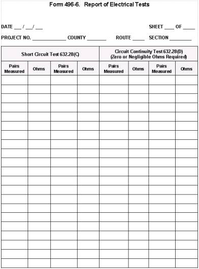
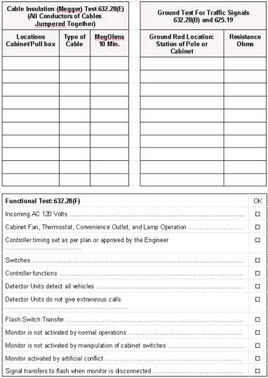
Figure 498-6. Concrete Pull Box
Figure 498-10. Strain Pole Supports
Figure 498-11. Strain Pole Attachment Details
Figure 498-12. Single Arm Support
Figure 498-13. Sag and Vertical Clearance Diagram
Figure 498-14. Cable Support Assembly

Figure 498-15. Aerial Interconnect Cable
Figure 498-16. Method of Measurement for Signal Cable
Figure 498-17. Method of Measurement for Interconnect Cable
Figure 498-18. Method of Measurement for Detector Lead-In Cable
Figure 498-19. Method of Measurement for Power Cable
Figure 498-20. Method of Measurement for Service Cable
Figure 498-21. Vehicular Signal Heads
Visors for Signal Heads
Hangers for Signal Heads
Figure 498-21. Vehicular Signal Heads

Wiring a Signal Head
Figure 498-22. Pedestrian Signal Heads
Figure 498-23. Loop Detector Placement and Installation
Loop Construction
|
Loop
Perimeter feet (meters) |
Number of Turns |
|
|
40 |
(less than 12) |
4 |
|
40-160 |
(12 to 49) |
3 |
|
over 160 |
(over 49) |
2 |
Figure 498-24. Loop Detector Slots and Wiring
Figure 498-24. Loop Detector Slots and Wiring

Figure 498-25.
Loop Detector Wiring
Figure 498-26. Magnetometer Probes and Lead-In
Figure 498-27. Ground Rod Testing

Figure 498-28. Short-Circuit Test
Figure
498-29. Circuit Continuity Test of
Loop Wire
(Before Splice to Lead-In Cable)
Figure 498-30. Circuit Continuity Test of Loop Wire and Lead-In Cable
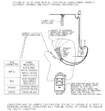
Figure 498-31. Circuit Continuity Test of Signal Cable Disconnected from Heads or Other Cables Such as Interconnect and Loop or Magnetometer Lead-In
Figure 498-32. Circuit Continuity Test of Signal Cable With Cable Connected to the Signal Heads and Lamps Installed
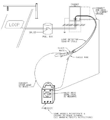
Figure 498-33.
Cable Insulation Test (Loop Detector Wire)
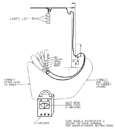
Figure 498-34.
Cable Insulation Test (Signal Cable)
Figure 498-35. SCD TC-81.20 Signal Support Design Chart
Figure 498-36. Plan Details for Strain Poles
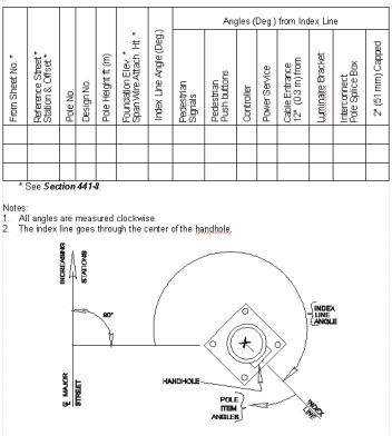
Figure 498-37. Plan Details for Signal Supports - Arm Lengths
(table is
continued in Figure 498-38)
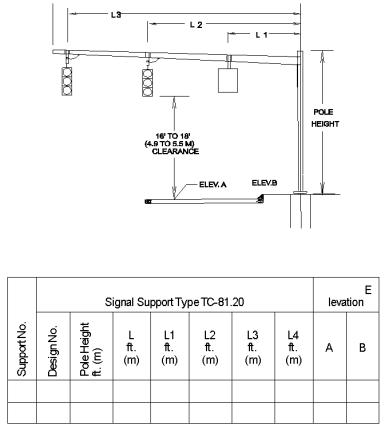
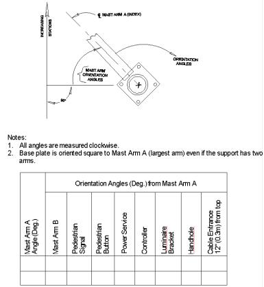
Figure 498-38. Plan Details for Signal Supports - Mast Arm Orientation
(table continued from Figure 498-37)