204 Subgrade Compaction and Proof Rolling
Specification and Plan Requirements
Subgrade Correction Prior to Proof Rolling
Implementation during Construction
Documentation Requirements – 204 Subgrade Compaction and Proof Rolling
Importance
Over 25 million dollars of extra work was used to stabilize soft subgrades during the construction seasons of 2000 and 2001. This extra work has been minimized in recent years because of the construction and design criteria created since that time.
This section will help the project construct stable subgrades for pavement construction. Proper subgrade treatment ensures a constructible pavement, enhances pavement performance over its life, and ensures that the pavement design intent is carried through in the construction phase. This section is based on research performed by the Department from the 1960’s through today. This section should not be used as the ultimate answer to solve all subgrade problems.
This section is detailed in such a manner so that construction personnel can easily apply information from the field and subsurface investigation to provide reasonable adjustments to the plan subgrade treatment.
Specification and Plan Requirements
Item 204 requires the top 12 inches of the subgrade to be compacted. Item 204 requires the subgrade to be proof rolled. If subgrade stabilization or undercutting is designed for the entire project, then proof rolling is only used to verify the undercut replacement material stability. If special subgrade treatment is provided in the plans at spot locations, proof rolling is specified to identify these areas and then performed afterwards to verify the undercut stability.
Proof rolling deflections and soil conditions that are observed during construction determine if the plan subgrade treatment must be adjusted. Adjustment of subgrade treatment to fit field conditions is essential and is the responsibility of the Project Engineer.
Subgrade Correction Prior to Proof Rolling
The Engineer must observe the effect of heavy equipment operating on the subgrade during rough grading. When rutting and deflection under heavy equipment indicates soft subgrade, the Engineer should authorize the correction. See “Elasticity and Deformation of Soils” in section 203.02 Materials of this manual.
Do not delay the correction until it can be checked by proof rolling. Investigate the extent of the problem by using the “Investigation” section of this Item. Be aware that the condition can be improved by time, drainage, and hauling as detailed in the section “Draining and Hauling” of this item.
If needed, make the correction by excavating and disposing of soft soil, and replacing it with suitable material as detailed in the section “Undercut Depth and Stabilization Determination” of this item.
Drainage and Hauling
Excess water in fine-grained soil is the principal cause of unstable soil conditions. The Engineer has a responsibility to ensure adequate drainage during construction. If the investigation indicates the need for underdrains or the cleaning of the existing underdrain outlets, then the Engineer must order the work as soon as possible.
Some examples of these conditions are as follows:
1. Existing underdrains with clogged outlets on rehabilitation projects.
2. Free water in the subgrade.
3. Saturated soils of moderately high permeability, such as sandy silt and silty clay of low plasticity.
4. Ground water seepage through layers of permeable soil.
5. Water seeping in the test pits.
6. Water seeping from higher elevations in cut locations.
7. Water flowing on the top of the rock or shale in subgrade undercuts.
Note: It is difficult to remove water from hard clay soils with PI’s greater than 20 with construction underdrains.
Subgrade stability can be significantly improved by cleaning out the existing underdrain outlets on rehabilitation projects and by adding construction underdrains on new or rehabilitation projects. Once the underdrain systems are in place and functioning, the drainage system can reduce the subgrade soil moisture content from 3 percent over optimum moisture to the optimum moisture content in 6 to 8 weeks. Moisture contents that exceed 3 percent over optimum must be dealt with by other means.
For rehabilitation projects, the Contractor should be instructed to unclog the underdrain outlets immediately. Try to perform this work in the time frame listed above. If the project consists of several phases, instruct the Contractor to perform the outlet cleaning for the entire project at the same time.
For new or rehabilitation projects, subgrade stability can be achieved by constructing the plan or construction underdrains as soon as the water problem is found. On new construction projects a longer period of time can be allowed for the underdrain system to work. Opportune times for this work are at the beginning of construction and before winter shut down.
The plan underdrains should be placed only when they will not be contaminated by further construction. If contamination is a concern then sacrificial or construction underdrains should be used on the project.
Item 605 in the C&MS details the construction underdrain construction. Construction underdrains are usually placed in the centerline of the roadway. They may also be placed in the ditch line if the water is coming in from a cut section at a higher elevation. The porous backfill is extended to the subgrade elevation. The outlets for the construction underdrain are the same pipe material and backfill as regular underdrains. The underdrains can be outlet to any convenient location such as catch basins, manholes, pipe, or ditches. The project should not be concerned with the contamination in the upper portion of the underdrain backfill. Construction underdrains are sacrificial underdrains that will continue to work throughout the life of the contract, and afterwards even though the upper portion is contaminated.
In Figure 204.A, the subgrade is saturated and the soil acts like a waterbed when the subgrade is Proof Rolled or hauled on. However, once the underdrains are in place and the soil is loaded, as shown in Figure 204.B, then the water has a place to go. As the soil is loaded or hauled on, the water is squeezed out and the subgrade conditions will improve.
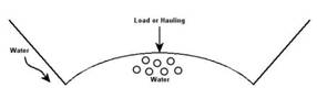
Figure 204.A – Water in the Subgrade without Drainage
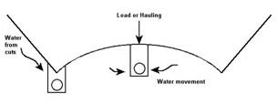
Figure 204.B – Water in the Subgrade with Drainage
By placing the drainage system prior to loading or hauling on the subgrade, the water is given a location to escape the subgrade system. If the drainage system is not in place before hauling or loading, the subgrade will rut or crack, and have a detrimental effect on the subgrade and not improve with loading.
Drainage and hauling can work together to correct soft subgrades under the above given guidelines.
Figure 204.C “Shale and Rock Undercuts” came from Figure 1009-10 in Location & Design Manual – Volume 2, Drainage Design. The specification requirements are detailed in 204.05. Shale and rock are cut 24 inches (610 mm) below the bottom of the pavement. This ensures that the pavement gets uniform support and good drainage. In addition, soft rock or shale can deteriorate due to the accumulation of water under the pavement.
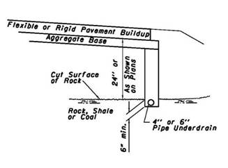
Figure 204.C – Shale and Rock Undercuts
The underdrains in these rock and shale cuts should extend at least 6 inches (150 mm) into the existing rock or shale formation. If the underdrains are too high, the water will accumulate at the rock and soil interface and cause subgrade instability.
Construction or rock underdrains can be placed in the ditches and other strategic locations in cut sections to minimize water coming under the pavement. Water under the pavement without drainage causes the subgrade to act like a waterbed. With drainage, the conditions improve and become more stable.
When to Proof Roll
For areas where subgrade appears to be stable without undercutting, proof roll after the top 12 inches (305 mm) of the subgrade meets the compaction requirements and after the subgrade has been brought to approximate shape within 0.1 to 0.2 feet (30 to 60 mm) required by plan lines.
For areas that are obviously unstable and require undercutting, do not proof roll unnecessarily to demonstrate that subgrade correction is required.
The proof rolling should be done immediately after the subgrade compaction operation, when the moisture content of the subgrade soil is near the optimum moisture content or at the moisture content that achieved compaction. This minimizes the subgrade becoming too wet or too dry for an effective proof rolling evaluation. If the subgrade is too wet, the material will displace and rut. If the subgrade is too dry, a hard surface crust may carry the proof roller over an undesirable soft wet underlying material without rutting or deflection, and the soft subgrade may not be detected.
Proof rolling may be done either before or after pipe underdrains are installed. If done after underdrains are installed, rolling should not be done directly over the underdrains. In C&MS 204.06, proof rolling must be performed at least 1.5 feet (0.5 m) away from the underdrains because of the potential damage to the underdrains.
Proof Rolling
CA-EW-2 “Proof Rolling Documentation Form” is used to document the proof rolling operation. It is imperative that the stations, deflections, weight of the proof roller, and comments are well documented. Digital photographs of subgrade distress are highly recommended.
The primary purposes of proof rolling are to locate soft areas, check the subgrade compaction, to carry out the intent of the design, and to provide uniform support for the pavement structure. Soft subgrade areas that are located will be corrected so that the subgrade density can be maintained throughout the construction. If done correctly, the pavement design intent will be carried through the construction process.
One trip with a proof roller is adequate to achieve satisfactory proof rolling results.
An over loaded proof roller for a soil type may cause satisfactory subgrade to become unstable during proof rolling. Conversely, soft areas will not be found if the proof roller is too light for the soil type.
Selection of Proof Roller Weights and Tire Pressure
In view of the many variations which must be expected in Ohio soil and moisture conditions, the Engineer is given authority to vary the weight and tire pressure of the proof roller to fit the conditions. The weights and tire pressures for the different soils are detailed in C&MS 204.06.
It is imperative that the project chooses the correct load for the type of soil on the project. These loads and tire pressures are soil type sensitive when evaluating the subgrade. For A-3, A-4, A-6, and A-7 soils, use a 35 ton (32 metric ton) roller with a tire pressure of 120 psi (820 kPa). This load and tire pressure is used on most projects because these are the most common soils found in the State of Ohio.
For granular soils, and soil, rock and granular mixtures, use a 50 ton (46 metric ton) roller with 150 psi (1030 kPa) tire pressure.
The goal of proof rolling is to maximize the load to locate soft subgrade. These soft soils could be 3 to 5 feet (1 to 2 m) deep. In rare cases, the soft soil may be deeper than 5 feet (2 m).
Close inspection throughout proof rolling is necessary to observe the rolling effects and to mark soft subgrade locations for correction or investigation. Inadequate stability is indicated by deflection, cracking, or rutting of the surface of the subgrade.
Failure Criteria
The failure criteria is used in this section to determine the locations from which to perform a detailed analysis. This detailed analysis consists of methods discussed later in this section such as rut depth, soil borings and test pits. If the subgrade deflects beyond the failure limits given in this section and the soil borings and test pits determine that the subgrade does not need to be undercut then the subgrade should be considered satisfactory. One additional area to evaluate is the moisture content of the soil. Some soils are more prone to rut at moisture contents greater than 3 percent below the optimum moisture content. In fill locations, the moisture content can be reduced to minimize this problem. If all of the above criteria are met then there is no reason the subgrade should not perform as anticipated. If there is any debate between the Department and the Contractor, especially if a warranty is involved, then further nondestructive or destructive testing can be used to resolve the issue.
The failure criteria for new construction and reconstruction projects are different because of the following reasons:
New construction projects
1. Longer construction time frames allow the subgrade to stabilize.
2. Haul roads to minimize the loading of the subgrade can be established for new construction projects.
3. Drainage and maintenance of these projects are much easier.
4. Even when rutting does appear during proof rolling, the material may be re-graded, hauled on, and re-compacted to meet the specifications.
Rehabilitation projects
1. The soil conditions under pavements are highly variable.
2. Water accumulates under the pavement because of the freeze thaw and wet dry cycles, high existing ditches and underdrain outlet clogging.
3. Construction time frames are limited.
4. Space limits the ability to dry the material in place.
5. Once the pavement is removed, all the drainage is toward the subgrade. This compounds an already poor drainage situation.
6. Alternate haul routes are limited or not available on rehabilitation projects.
The Criteria
In all situations, the maximum allowable rutting or elastic movement of the subgrade is the amount that allows the subgrade soil to maintain the specified density throughout the construction process. For example, if subgrade density can be maintained with 6-inch ruts, then this would be the allowable maximum.
The Contractor must be afforded reasonable use of the subgrade for hauling and for constructing the base material. If subgrade density cannot be maintained through reasonable use of the subgrade, then the allowable proof rolling rutting is too much. If the project conditions allows, areas other than the subgrade should be used as haul roads. For a Contractor ‘to bid’ to haul loaded trucks or scrappers endlessly across the subgrade throughout the life of the project is going above and beyond the reasonability test. At a minimum, the Contractor should be allowed the use of the subgrade to place the base material with vehicles of legal weight.
The following criteria have worked in the vast majority of the projects.
For new construction projects, permanent rutting in excess of 1 inch (25 mm) should be considered failure. In addition, elastic (rebound) movement or rutting in excess of 1 inch (25 mm) with substantial cracking or substantial lateral movement should be considered failure. Rutting and cracking greater than detailed above is considered “pronounced elasticity.”
Elastic, rebound, or rolling movement is always associated with excess water in the subgrade system.
For reconstruction projects, permanent rutting greater than ½ inch (13 mm) should be considered failure. In addition, elastic (rebound) movement or rutting in excess of ½ inch (13 mm) with substantial cracking or substantial lateral movement should be considered failure. Rutting and cracking greater than detailed above is considered “pronounced elasticity.”
When deflections are greater than these criteria, there is no assurance that overlying pavement construction will not damage the subgrade compaction. Although subgrade density and stability can be maintained during the proof rolling, the repetitive loading, hauling of materials, and base and pavement construction can destroy the subgrade compaction.
See Figures 204.D, 204.E and 204.F.
In Figure 204.D, the soil has been compacted in the top foot of the subgrade and the conditions are good for the top 3 feet (1.0 m). However, there is a soft layer at a lower elevation. The soft layer has no detrimental effect on the subgrade density during the subgrade compaction.
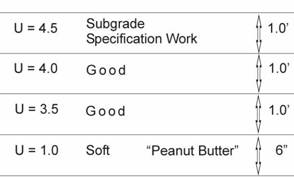
Figure 204.D - Stage 1 Compaction of Subgrade
In Figure 204.E the proof roller deflects because of the soft soils. The subgrade density may or may not be affected by the proof rolling. The loss of subgrade density is proportional to the amount of rutting or elasticity during proof rolling and subsequent construction operations. The severity of the overall subgrade condition can be measured by the amount of the deflection and elasticity on the surface.
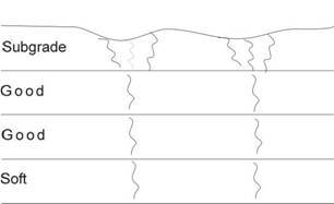
Figure 204.E - Stage 2 Proof Rolling
In Figure 204.F, when the deflections exceed the failure criteria, the proof rolling, repetitive loading, and pavement construction can destroy the top layers of the subgrade.
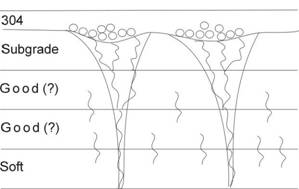
Figure 204.F - Stage 3 Hauling, Grading, and Placing 304
In actual field conditions, this soft layer can be just a few inches thick and at any elevation from the top 1 foot (0.3 m) to as deep as 5 feet (2 m). In addition, it may be an indication of an overall soil condition that is just over optimum for the entire 5-foot (2 m) depth of the subgrade. The field excavation is used to identify the layer or layers causing the surface distress is detailed in the section “Investigation” of this Item. Therefore, it is imperative that these conditions are correctly identified.
As shown in Figure 204.H “Subgrade Treatment Chart” subgrade constructability is suspect at curve locations to the left of the triangles. Further details are given in the section “Undercut Depth and Stabilization Determination” in this Item.
Crusting is a condition when the subgrade surface appears to be dry and there is substantial cracking on the surface with or without rutting. This indicates a need for further investigation and usually indicates soft or wet underlying soil with the top foot or so of the subgrade being very dry.
Variations in the Proof Rolling Results
The project should not be concerned with occasional or nominal deflections in excess of the above failure criteria. If the density is checked and the investigation shows that good soil extends throughout the top 5 feet of the subgrade, then the design intent will be fulfilled and the project can be constructed. All soils will occasionally deflect under these loads.
The pavement design is based on an average CBR. The CBR value was directly correlated to soil density many years ago. By using the average CBR (Density) value, the pavement design accounts for a 30 percent, or one standard deviation variation, in the subgrade strength from the design CBR; 15 percent is expected to exceed this value and 15 percent is expected to be less than this value. Therefore, some variation in the subgrade condition is already accounted for in the pavement design.
Another consideration is the fact that these proof rolling loads and tire pressures are about 10 times the final in-place stresses once the pavement is constructed. The proof rolling tire pressures are between 120 to 150 psi (820 to 1030 kPa) and the stresses once the pavement is constructed are about 8 psi (55 kPa) for a thin asphalt pavement and 4 psi (27 kPa) for a thick concrete pavement. Therefore, these loads are the largest loads that the subgrade will encounter.
If the project can be constructed while maintaining subgrade density, then the subgrade design intent will be fulfilled.
The project should not be concerned with the “Pavement Warranty” issues that Contractors often bring up. If the project follows theses guidelines and properly documents the subgrade work, Central Office can defend the warranty issue.
Once failure is established based on the proof rolling results, then the responsibility for the correction of the failure should be determined.
Responsibility for the Soft or Failed Subgrade
If soft or failed subgrade locations are found, take compaction tests to determine if the specifications are met in the top 12” (300 mm). The Engineer should instruct the Contractor to correct any deficiencies found in these locations.
The Department is responsible when the soft or failed subgrade is encountered in:
1. Cuts.
2. On rehabilitation projects.
3. In shallow fill locations where the soft material is found under the contract fill.
4. When the soft material is found at lower elevations than the project contract work.
Subgrade stability may not be possible by compacting the upper 12 inches (0.3 m) because of conditions at these lower elevations.
It is the Contractor’s responsibility to correct all failed or soft locations in fills. If the Contractor built the fill correctly, the proof rolling will do nothing but verify specification work. If the fill fails then the proof rolling will determine the location of the deficient specification work.
If the Contractor fails to maintain the subgrade, then the Engineer should instruct the Contractor to repair the failed areas. See C&MS 203.04.A for the Contractor’s responsibility to drain and maintain the subgrade.
Investigation
Investigate the causes of failed locations quickly to expedite the corrective treatment. Three pieces of information are needed to make the most economical subgrade treatment:
1. Rut Depth
2. Soil Boring Information
3. Test Pit Data
At this point the rut depth has already been determined.
Soil Boring Information
For rehabilitation projects or cut sections, the soil borings can be examined to determine an estimated undercut depth or stabilization methods.
Evaluate standard penetration test (SPT) results from soil borings in the failed subgrade locations. The standard penetration test (SPT) is an indicator of the soil consistency or strength, and measures the number of blows per foot (N) required to drive the soil sampler through the soil. The soil data on the boring logs are presented as the number of blows required to drive each 6-inch (150 mm) increment. The first 6 inches (150 mm) of the run is ignored because the sampler may not be seated in the borehole or may be driven through cuttings. For example, standard penetration data shown as 1/2/3 has an N value of 5 blows per foot.
When investigating the need for undercutting or stabilization in failed locations, look at the borings in those locations in the upper 5 feet (1.5 m) of the subgrade. At each location, pick the lowest N value when multiple N values are taken in the top 5 feet (1.5 m) of subgrade.
Average the N value along the failed locations. This value provides one part of the information needed to determine the undercut depth or stabilization methods.
Test Pits
Once the soil borings have been evaluated, construct test pits by excavating 3 to 5 feet (0.6 to 1.5 meter) into the subgrade using the Contractor’s excavation equipment. Excavate at least two test pits that represent the failed area. Use judgment for long areas; usually about two to four test pits per mile is sufficient. Construct the test pits across the width of the subgrade in the failed locations. Pick locations with the highest deflections to evaluate the most severe locations.
Warning: These trenches may collapse on the construction personnel. The Department offers an 8 Hour Construction Safety Class to evaluate the trench collapse risk. In addition, there is a trench safety class offered by the Bureau of Workers Compensation, Division of Safety and Hygiene. These classes are given statewide all year around. (614-466-5563)
An examination of the soil and moisture conditions in these test pits provides valuable information to make the appropriate correction. Once the pits are excavated, the Engineer must examine the trench sidewalls and the bottom of the cut.
Record the test pit information on CA-EW-3, “Subgrade Test Pit Investigation” form shown in Figure 204.G. The soil conditions vary with depth and must be quantified. By examining the sidewalls, the Engineer can determine the soil type, layer thickness, soil condition, and soil strength by using a hand penetrometer.
Figure 204.G – Form CA-EW-3 Subgrade Test Pit Investigation
The Engineer must field classify the soil. See 203.02 Materials, “Identifying Soil and Granular Materials in the Field” for help in the classification.
Added soil conditions are described on the bottom of the test pit form. These conditions are stated in commonly-known consistencies, so that the non-geotechnical reader can relate to the soil conditions. They are listed on the bottom of the form. No explanation is needed for these terms.
Hand Penetrometer Readings
A hand penetrometer can be used to further classify the soil and to estimate its strength. A hand penetrometer can be obtained from a test lab supply company for less than $100. Hand penetrometers can be obtained from the following companies:
|
Gilson |
Model # HM-500 |
Phone 800-444-1508 |
|
ELE |
Model # E129-3729 |
Phone 724-864-3364 |
|
Humboldt |
Model H-4200 |
Phone 800-444-7220 |
The exact instructions come with the hand penetrometer. In summary:
1. Push the hand penetrometer slowly into the soil at right angles.
2. Record the reading when the hand penetrometer penetrates the soil to the ¼‑inch groove mark.
3. Record the readings to the nearest 0.25 tons per square foot (tsf).
4. Take at least three different readings in each soil layer.
Use CA-EW-3 “Subgrade Test Pit Investigation” form to record the readings. Average the readings once three readings are taken for the soil layer. Also evaluate the bottom of the test pit; this is extremely valuable information. Once the averages are determined, record the lowest average unconfined reading on the bottom of the form. This would be the most critical soil layer.
Average the unconfined readings (U) of all the test pits in the failed locations. Use this number to further evaluate the undercut depth or stabilization methods.
Consider the following when evaluating the sidewalls of a trench:
1. Different layers of a natural formation or cut are more noticeable than fill materials.
2. High unconfined numbers may be obtained with high deflections or rolling at the surface. This is an indication of soft soil at a lower elevation than 5 feet (2 m) or a subgrade soil that is just too wet.
Undercut Depth and Stabilization Determination
Once the proof rolling rut depth (in inches), soil boring information (N), and unconfined data from the test pits (U) are obtained, use the “Subgrade Treatment Chart” in Figure 204.H to determine the undercut depth requirements. The input values (rut depth, N and U) are on the horizontal axis. The two curves denote the type of project under construction. The left vertical scale shows the undercut depth in feet of granular material. The right vertical scale shows the stabilization depth required in inches of lime or cement.
Figure 204.H - Subgrade Treatment Chart
The horizontal dashed line at about ½ foot indicates that treatment is not required for results below this line. The top portion of Figure 204.H details the general subgrade condition.
Figure 204.H takes into account the standard deviation of test results, anticipated truck loading, and type of project under construction.
Use the rut depth, N values, and unconfined strengths (U) from a hand penetrometer to draw a vertical line to the curve for the type of project under construction. At that intersection draw a horizontal line to the left and right. This determines the granular undercut depth or stabilization needs.
The undercut chart gives the required stabilization method to obtain stability when the undercut or stabilization is completed.
It would be rare to see a perfect alignment in the results from all three inputs. In some cases, one or two of these inputs may not be available. In other cases, some judgment is needed to redesign the most economical undercut that will work. In order of hierarchy, use the test pit data, then the N values, and then the rut depth. The rut depth is the least reliable indicator of undercut need because it cannot determine which soil layer is causing the deflection.
There will be cases where the N values and unconfined values are all high but the subgrade is rolling and cracking, and rut depth is greater than allowable. In this case use the rut depth as a guide to redesign the undercut. See the last example in the example section.
There is an example in Figure 204.I.
Given: 5 mile
long Rehabilitation Project
Average N value was 12
U= 1.4 tsf
Average Rut Depth was 2-4 inches.
Answer: Use an undercut depth of 2.0 feet (0.6m) or stabilize with 12-16 inches of cement or lime. Since this is a long project, give serious consideration to the stabilization method. It will be more cost effective.
![]()
![]()
![]()
![]()
Figure 204.I - Example using the Subgrade Treatment Chart
After making the undercut, this depth may need to be adjusted to meet the actual conditions. See the section, “Implementation during Construction” of this manual.
General Rules
On new construction projects, if all of the soft material can be removed and the bottom of the test pits or cuts are stable, then soil may be used as replacement material. For reconstruction projects, soil is usually not available in large quantities and the bottoms of the cuts are highly variable. Therefore, soil undercuts are less effective solutions on reconstruction projects.
If the bottom of the test pit is unstable, when conditions are highly variable, or for rehabilitation projects then use granular material, rock, geotextile, or lime or cement stabilization, rather than soil.
Undercuts should be used in small locations or in areas where spot locations are identified. Consider cement or lime stabilization for long areas greater than one mile.
Only the most unusual cases require removal to depths greater than 3 feet (1 meter). Seventy five to ninety percent of subgrade problems can be solved with a one-foot treatment of granular material and geotextile or stabilization with lime or cement. Use stabilization methods for projects with long areas to stabilize or when the undercut depth is greater than 1.0 foot.
If a project or section of a project undercut locations are more than 30% of the total area, undercut or stabilize the entire area. If you do not undercut the entire area, these locations will grow and the construction will be inefficient as the construction proceeds. The Department pays a higher cost at a reduced final quality by undercutting a high percentage of the subgrade throughout the project. ODOT would not repair a bridge deck or pavement with this high a percentage of repairs.
Stabilization methods speed construction because of the ability to work immediately after a rain. Estimates indicate that the construction production is increased by at least 50 percent by using stabilization methods.
Examples
The following table shows some example solutions. The types of material refer to 703.16.C and Item 206.
|
Given |
Solution |
|
Rehabilitation Project with Silty A-4a material with N=15 or U=2.0 tsf Rut Depth>1" |
1.5 feet of Granular Material Type B, C or D with geotextile or 12 inches of stabilization with cement |
|
Rehabilitation Project with Deep, weak, and wet A-4 with N = 12 or U=1.4 tsf Rut Depth = 2" |
2.0 feet of Granular Material Type B, C, or D, with geotextile or 12-16 inches of stabilization with cement |
|
New Construction, Deep, weak & wet A-4, A-6 or A-7-6 combination with N = 10 or U=1.0tsf. Rut Depth = 4" |
1.5 feet of Granular Material Type B C or D with geotextile or 12 inches of stabilization with lime or cement. (Check the PI of the soils. Use the stabilization type according to the PI’s of the soil.) |
|
New Construction Jell-O like consistency soil with N = 5 or U=0.5 tsf. Rut depth > 6" |
2.5 feet of Granular Material Type B, C, or D, with geotextile or 16 inches of stabilization with cement. ( Check the PI of the soil.) |
|
Any Project with soup like consistency soil with N = 2 or U=0.25 tsf Rut Depth = Buried equipment |
5 feet of Granular Material Type B, C, or D, with geotextile. (May need two layers of geotextile, Use type D Granular Material if available) |
|
Reconstruction Project Sandy, A-4a, A-6a soil, PI < 20, N = 8 or U=1.0 tsf Rut Depth = 6". (Long Project) |
Cement Stabilized Subgrade 16" deep at 6% |
|
New construction A-7-6 clay soil, PI > 20 N = 11 or U=1.2 tsf Rut Depth =3". (Long Project) |
Lime Stabilized Subgrade 12" deep at 5% |
|
Reconstruction Project A-6a silty clay PI < 20, N=30 and U>4.5 tsf Rut depth > 2" and rolling The key here is the rolling. Probably caused by high moisture content of the soil at a depth. If the subgrade is rolling with one pass of a proof roller then the subgrade condition can rapidly deteriorate during construction. |
16" of Cement at 6% or 2.5 foot undercut with Granular Material Type B, C, or D, with two layers of geotextile. Use Type D material if available. |
Type of Undercut Materials
Use Granular Material Types B, C, D, E, and F. They are cheaper than 304.
Type B is a well-graded aggregate with the gradations of Items 304, 411, or 617. Type C has a top size of 3 inches and type D has a top size of 8 inches. Both C and D are well-graded materials. The larger top size material will bridge the soft material better that the smaller size material.
Use Granular Material Type E when water levels are high or cannot be drained. The Type E materials are very porous. Always choke the Granular Material Type E with Granular Material Type B or geotextile fabric.
There is a potential for piping of soil into the Granular Material Type E as shown in Figure 204.J. In the upper detail, when the open material is placed on soft fine graded soil, the soil pipes into the open graded material during construction or by loading. In the lower detail, the geotextile fabric blocks the material from entering the open graded material. Geogrids will not work for this application.
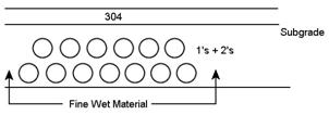
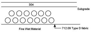
Figure 204.J - Soil Piping in Open Material
Underdrains cannot be placed through Granular Material Types D, E, or F or geotextile fabric. Use Granular Material Type B in the locations of the underdrains. Always drain the undercut to an underdrain, catch basin, or pipe.
Always use 712.09 Geotextile Fabric Type D. The cost is around $1.00 per square yard. In the case of deeper undercuts, multiple layers can be used at a 12-inch vertical spacing if needed.
Cement and Lime Stabilization of the Subgrade
Item 206 Chemically Stabilized Subgrade can be used to treat unstable subgrades. Lime or Cement can be used to stabilize the subgrade.
Lime is used for A-6b (silty/clay) or A-7-6 (clay) soils which have a plasticity index of 20 or greater. Use 5 percent lime by dry weight of the soil assuming a dry weight of 110 pounds per cubic foot.
Cement can be used to treat unstable subgrades consisting of A-3 (fine sand, coarse and fine sand), A-2-4 through 7 (gravels), A-4a (sand silt), A-6a (silt and clay), A-6b (silty clay), or A-7-6 (clay) which have a plasticity index less than 20. Use 6 percent cement by dry weight of the soil assuming a dry weight of 110 pounds per cubic foot.
See Item 206 Chemically Stabilized Subgrade of this manual.
Implementation during Construction
Once they type of stabilization treatment has been chosen, constant monitoring of the construction is required to adjust the treatment to meet the field conditions. Soil conditions always vary; they vary the most on rehabilitation projects or in cuts.
If the undercut option is chosen, the project should monitor the bottom of the cut and evaluate the condition. Take hand penetrometer readings at the bottom of the cuts and compare them to the initial test pit or soil boring information. If the condition changes from the earlier evaluation of the test pits or the soil borings, then adjustments to the undercut depth are required.
In addition, for undercuts that are two feet deep or greater, give consideration to placing multiple layers of geotextile fabric. The need for additional layers of geotextile can be determined by placing about ½ of the undercut depth. Load the undercut with a fully loaded truck. If the area is unstable, then place another layer of geotextile and continue to fill the undercut.
Once the undercut or stabilization is complete, proof roll the area to ensure that the final subgrade meets the rut depth and density requirements as detailed earlier in section “Failure Criteria”.
Constant vigilance is needed in order to make the most economical correction. It is easy to over-excavate unnecessarily and waste money. It is more difficult to make the right economical choice to stabilize the subgrade and to meet the design and construction needs.
Documentation Requirements - 204 Subgrade Compaction and Proof Rolling
1. Materials.
2. Compaction according to S-1015.
3. Lift thickness and roller passes.
4. Equipment used.
5. Type of soils.
6. Verify square yardage.
7. Verify subgrade line and grade.
8. Proof Roll and make corrections.
9. Subgrade Test Pit Investigations.
10. Undercut measurements.
11. Document on CA-EW-1,CA-EW-2,CA-EW-3, CA-EW-8, CA-EW-12 and CA-D-3. Do not duplicate the information on all forms unless necessary.