499 Concrete – General
Control of concrete is
divided into two categories: large quantity critical usage and small quantity
non-critical usage. All pavement and
structure concrete, and in general any other concrete usage exceeding 200 cubic
yards (150 cubic meters) per day, is considered large quantity critical usage.
When placing small quantity
non-critical usage concrete from sources having a record of supplying approved
material, the concrete may be accepted by field tests and backed up by random
test beams, concrete cylinders, and random plant inspections as deemed
necessary by the Engineer. The following
list shows examples of small quantity non-critical usage concrete:
1. Sidewalks - Not to exceed approximately 500 square
yards (418 square meters) per day.
2. Curbing, combination curb, and gutter - Not to exceed
approximately 500 linear feet (152 linear meters) per day.
3. Patching and temporary pavements.
4. Building foundations and floors.
5. Slope paving and paved gutter.
6. Guardrail and fence post anchorages.
7. Metal pile castings.
8. Culvert headwalls.
9. Catch basins, manhole bases, and inlets.
10. Sign, signal, and light bases.
Acceptance of concrete under
the small quantity non-critical usage procedure does not waive the
responsibility for using approved materials.
Concrete accepted under these provisions must be reported using an
abbreviated TE-45
form along with company tickets indicating quantity, class, slump, and air test
results and time of batching.
At least one concrete control
inspector must be present whenever small quantity non-critical usage concrete
is being placed and two or more inspectors are required for large quantity
critical usage placement.
Introduction
Concrete used in highway
construction is a mixture of coarse aggregate, fine aggregate, Portland cement,
water, entrained air, and permissible mineral or chemical admixtures. In this mixture, each aggregate particle is
completely coated by a paste of cement and water. This paste binds the aggregate particles into
a mass called concrete. The cement paste
can consist of Portland cement, fly ash, ground granulated blast furnace slag,
or microsilica, water, air voids, and any
admixtures. The cement paste comprises
from 25 to 40 percent of the total concrete volume. To have quality concrete, it is necessary
that both aggregate and paste be sound and durable.
Aggregate, cement, and
admixtures to be used in concrete are sampled and tested by the Laboratory to
ensure that ingredients meet quality standards.
However, the quality of the paste depends on proper construction
techniques. These techniques include the
minimum use of water and favorable temperature and humidity during the curing
period.
Approximately 30 pounds of
water is required to complete the chemical reaction with 100 pounds of
cement. Although a small amount of water
is needed to complete the chemical reaction with cement, additional water is
necessary to make the concrete workable.
As the paste is thinned out with water, its quality is lowered: it will
have less strength and less durability.
For quality concrete, a proper proportion of water and cement is
essential. This proportion is called water-cement ratio. The water-cement ratio
is determined by dividing the weight in pounds (kilograms) of the total actual
mixing water by the weight in pounds (kilograms) of cement used in the
mix. A maximum water-cement ratio is
specified to avoid excess water and to ensure quality paste, and therefore,
quality concrete.
To provide a dense mixture of
the aggregate, cement, and water, it is necessary to have various sizes of
aggregate particles so that the smaller particles fill the voids between the
larger particles. Therefore, aggregate is divided into two categories: coarse
aggregate and fine aggregate. Coarse aggregate is aggregate with 95 to 100
percent of its particles larger than the 4.75 mm (No. 4) sieve. Fine aggregate is aggregate with 95 to 100
percent of its particles smaller than the 4.75 mm (No. 4) sieve. Coarse and fine aggregate are graded, that
is, they contain several sizes of particles combined together. When placed in
concrete, these various sizes of particles become coated with the cement paste
and form a dense mass with the voids filled.
In addition to requirements
that it be strong and dense, concrete must be durable. Durability means
resistance to the elements. Concrete
that is not exposed to the elements such as water, freezing, and thawing, generally
will be durable. When non-durable
concrete is subjected to these destructive forces, scaling and deterioration
generally follows and progresses with each cycle of freezing and thawing unless
preventive measures are taken. In order
to provide concrete with additional durability, an air-entraining admixture is
added to the concrete to generate billions of air bubbles of microscopic size
in the concrete. This air-entraining
agent may be interground with the cement, or it may
be an admixture, or both. These
microscopic air bubbles form in the paste of the concrete as it hardens and
create tiny air pockets in the hardened concrete. When moisture is present and
freezing takes place in air-entrained concrete, the water expands and moves
through capillaries to these very small air pockets and the expansive force is
relieved. Without these relief air
pockets, the forces created by the expanding ice formation would rupture the
concrete at its surface. This rupturing is known as scaling.
Basically, this is the theory
of concrete mixes. Quality concrete
consists of a mixture of sound, durable, fine-graded, and coarse aggregate
mixed together with cement, water, and air entrainment. When properly mixed,
placed, and cured, the resultant concrete has strength and durability and provides
the service life for which it was designed. Only by vigilant inspection can
fulfillment of these requirements be ensured.
Duties and Responsibilities
The concrete control
inspector is responsible for the fulfillment of all required tests and validation
of all specification requirements for concrete. The Inspector cannot alter or
waive any provision of the proposal, plans, or specifications. Any failure of
the work or materials to conform to specifications must be corrected
immediately. If necessary, production must be stopped for correction rather
than permitting work that does not meet specification requirements to
proceed. The Inspector must notify the
Contractor and the Engineer of such action. The Inspector's duties include
verifying that approved materials are used, verifying the Job Mix Formula (JMF) is approved, performing tests as outlined in this
manual, requiring adjusts of the mix when out of specification allowances, and
enforcing the mixing requirements for the mixes used.
Copies of forms to be filled
out or verified by the Inspector are interspersed within the text of this
section and the use of the forms is described.
Materials (499.02)
All materials to be used in
the production of concrete must be tested and approved or accepted by
certification prior to use. A copy of
the Laboratory report or e-mail indicating approval of material must be in hand
before a material is used. When
necessary, material may be used when notification of its approval has been
given by phone from the Laboratory, provided the phone approval is recorded in
the project records prior to use. When
written approval is received, it is filed in the project records. No material is used unless it is determined
that it has been approved.
Portland Cement
Cement generally is shipped
in bulk quantities by truck from the cement plant or terminal to the concrete
plant. The cement normally will be from
a plant operating under the "Cement Certification Procedure" outlined
in Supplement
1028 and will require a 1/2-gallon sample which equals to a 10-pound (4.6
kg) sample every 180 days from each ready mixed concrete plant. The Office of Materials Management
(Laboratory) or the District Test Lab typically samples Portland cement.
Normally Type I Portland
cement (701.04)
is used. However, the general specifications permit the use of Type IA air
entraining Portland cement (701.01),
Type II moderate sulfate resistant Portland cement (701.02),
Type III high-early strength Portland cement (701.05),
and Type I(SM) Portland blast furnace modified slag cement (701.09).
An approved air-entraining
admixture is required to provide the specified air content when non-air
entraining cements are used and may be required if air-entraining cement is
used to obtain the proper amount of air.
Only Type I (701.04)
Portland cement is the standard cement used.
There are other cement options in 701
but they may only be used when accepted within the JMF.
If high-early-strength
concrete is specified, Type III must be used.
If moisture is exposed to
cement prior to mixing, it may cause the concrete to have slower setting time
and reduced strength. Therefore, cement
must be stored in waterproof bins or silos.
Truck transports generally
load the cement into the storage bins using compressed air, so it is important
that adequate vents are placed at the top of the bins. Unless adequate vents
are provided, cement must not be loaded at the same time concrete is being
batched. Small or restricted vents may be inadequate and could result in
inaccurate weighing of the cement at the time cement was being loaded into the
bins.
Aggregate
Fine and course aggregate
must be approved prior to use under the Supplement
1069 Pre-qualified Aggregate Supplier Program and meet the requirements of
703.01. Pre-qualified aggregate
suppliers and producers are listed on ODOT’s website.
Controlling the use of
aggregate is the responsibility of project personnel, while the Laboratory is
responsible for approving material.
Fine Aggregate
Fine aggregate for concrete
includes natural sand and sand manufactured from stone. Natural sand is required to be used in any
exposed concrete riding surface including 255,
256,
451,
452,
526,
and 511
(bridge deck concrete).
Fine aggregate consists of
relatively small particles and does not tend to separate as much as coarse
aggregate. Therefore, segregation
generally is not a problem with the fine aggregate unless extremely careless
methods of handling are employed.
Coarse Aggregate
If concrete is used for 305,
451, or 452
pavement it must also comply with 703.13
which is a test for freeze-thaw resistance (D-cracking susceptibility).
Coarse aggregate is a graded
material consisting of a combination of various particle sizes that require
extreme care when handling to prevent the smaller particles from separating
from the larger ones. The separation
that may occur during handling is known as segregation. If aggregate is dropped from a bucket or from
a belt and allowed to form a cone-shaped stockpile or if it is pushed over the
edge of a stockpile, the larger aggregate particles will roll to the bottom,
outside edge of the pile. The smaller
particles are less likely to roll because of their small size and weight and
remain closer to the center. This
results in a segregated stockpile.
Non-uniformity results when such material is used in the concrete mix
and difficulty can be encountered in controlling the water demand, slump, and
yield of the resultant concrete.
Coarse aggregate must be
maintained with uniform moisture content above saturated surface dry
condition. Watering or sprinkling of
aggregate may be desirable to provide concrete of uniform slump, to lower the
aggregate temperature during hot weather, in addition to overcoming the
possibility of a rapid slump loss. When
placing concrete during freezing weather, however, it is impractical to water a
stockpile to maintain uniformity.
When sprinkling is desirable,
it should be done in advance so that the water will be distributed uniformly
throughout the stockpile. If stockpiles
are large or contain aggregate having high absorption, such as slag, it may be
necessary to start watering several days in advance. However, the sprinkling
should be discontinued to permit excess moisture to drain off overnight.
Microsilica
Microsilica, also known as silica fume or condensed silica fume,
is a pozzolanic admixture that must comply with 701.10.
In its finely-divided form and in the presence of water, it will chemically
react with calcium hydroxide released by the hydration of Portland cement to
form compounds with cementitious properties.
This light to dark gray powdery product is the result of the reduction
of high-purity quartz with coal in an electric arc furnace in the manufacture
of silicon or ferrosilicon alloys.
Silica fume rises as an oxide vapor from a furnace 3,630 °F (2,000 °C). It cools,
condenses, and is collected in cloth bags. The condensed silica fume is then
processed to remove impurities and control particle size.
Condensed silica fume particles
are 100 times finer than cement particles.
The specific gravity of silica fume varies between 2.10 and 2.25 but can
be as high as 2.55. When used in
concrete it will fill the void space between cement particles resulting in
impermeable concrete.
Microsilica or condensed silica fume is provided in dry densified powder form and must be protected from
moisture. The microsilica
normally will be from a plant operating under the "Microsilica
Certification Procedure" outlined in Supplement
1045 and will require a 10-pound (4.6 kg) sample every 180 days from each
ready mixed concrete plant.
Ground
Granulated Blast Furnace Slag (GGBFS)
Ground Granulated Blast
Furnace Slag (GGBFS) is a material that may be
allowed or required by certain specifications. It is used as a cement
replacement. The GGBFS material is produced from
granulated blast furnace slag granules that are ground to a consistency
somewhat finer than cement. The granules are produced by tapping molten slag
from an iron blast furnace and using high-pressure water to rapidly quench the
material. The granules produced have a
consistency and color of sand and are composed primarily of glass. The granules are then ground in a cement mill
into a fine white powder.
The material is required to
meet the ASTM C 989
Specification. This specification identifies three grades of material: Grade
80, Grade 100, and Grade 120. Only
Grades 100 and 120 are permitted under the Department's specifications. GGBFS generally is
shipped in bulk quantities by truck from the cement plant or terminal to the
concrete plant. The GGBFS
normally will be from a plant operating under the "GGBF
Slag Certification Procedure" outlined in Supplement 1034 and will require
a 10-pound (4.6 kg) sample every 180 days from each ready mixed concrete
plant.
Concrete produced using GGBFS will have a slower strength gain in cooler
temperatures than normal mixes without it.
Due to this, there are certain prohibitions for its use during cooler
temperatures; GGBFS must be kept dry as with Portland
cement and fly ash. It is handled
generally in the same manner as cement and fly ash. It is normally delivered in bulk; however,
for a small project, it can be provided in bags. In either case, it should be
stored in a dry location.
Fly Ash
When coal is used to fire the
boilers of modern power stations it is first finely ground or pulverized to the
fineness of face powder before being fed into the furnace. The burning powdered coal gives off heat to
generate electricity, any coarse particles fall to the bottom of the furnace,
and hot gasses given off are swept away to be exhausted up the
chimneystack. The fine particles that
are in this exhaust and which are trapped before passing into the atmosphere
are "fly ash." During the combustion process, the bulk of these
particles assume an almost spherical shape, like microscopic ball
bearings. One of the properties of fly
ash is that, in the presence of hydrating Portland cement, it behaves like
cement. Fly ash reacts with calcium hydroxide to form compounds possessing
cementitious properties.
Two classes of fly ash are
allowed for concrete in 701.13. The two classes are Class F and Class C. Class F fly ash is produced from burning
anthracite or bituminous coal. Class C
fly ash is produced from burning lignite or sub-bituminous coal. Class F fly ash is the type normally found in
Ohio. However, Class C fly ash is also
becoming available to concrete producers now. Class C fly ash has some
cementitious properties by itself while Class F does not.
Fly ash used in Department
work must meet the requirements of ASTM C 618 except the maximum
loss on ignition (LOI) must not exceed 3
percent. The LOI
is a measurement of the carbon content or unburned coal in the fly ash. In order to maintain air entrainment at a
particular level (in concrete containing fly ash), the fly ash must have a low LOI. The ASTM specification allows a higher LOI than our specifications. ODOT specifications require the lower LOI to minimize problems entraining air in the concrete.
Fly ash will normally be
shipped in bulk quantities by truck from the power station to the concrete plant. Fly ash, like cement, has a certification
process. This process is described in Supplement
1026, “Fly Ash Certification”.
Certified fly ash requires a half-gallon (2L) sample every 180 days from
each ready mixed concrete plant.
Non-certified fly ash shall be sampled every 100 tons (91 metric tons)
and be approved prior to use.
Concrete containing fly ash
is permitted only between April 1 and October 15 due to slow strength gain in
cold temperatures.
Bulk fly ash must be stored
in waterproof bins prior to use.
Normally fly ash is handled in the same manner as cement. Only one source of fly ash is permitted in
any one structure unless otherwise approved by the Director.
Air-Entraining
Admixture
Air-entraining admixtures are
used to entrain the proper amount of air in concrete for freeze thaw
durability. These admixtures must comply
with 705.10 and conform to Supplement
1001 Approval and Testing of Air Entraining Agents and Chemical Admixtures
for Concrete. The list of approved air
entraining admixtures for Department use can be obtained from the SiteManager or from the Qualified
Products List (QPL) on the ODOT website.
Air-entraining admixtures are
randomly sampled at the concrete plant.
The Laboratory generally takes these samples.
Chemical
Admixture for Concrete
Approved set-retarding or
water-reducing and set retarding admixtures are permitted in order to increase
the workability of the concrete and to extend the time of discharge from 60 to
90 minutes. These admixtures are
permitted and often required for superstructure concrete.
Should the Contractor propose
to use calcium chloride as an accelerator in the concrete, it must be
determined if such use is permitted by specification, plan, or proposal
note. If not, the Contractor must
request permission of the Director, in writing, to use such admixtures.
Admixtures used under 499
must meet the requirements of 705.12
that specify that they meet ASTM
C 494, except that the relative durability factor shall be 90. These admixtures must comply with Supplement
1001 Approval and Testing of Air Entraining Agents and Chemical Admixtures
for Concrete.
The list of approved
admixtures for Department use can be obtained from the SiteManager
or from the Qualified
Products List (QPL) on the ODOT website.
Chemical admixtures as
defined by ASTM C 494 include:
·
TYPE A - Water
reducing
·
TYPE B -
Retarding
·
TYPE C -
Accelerating
·
TYPE D - Water
reducing and retarding
·
TYPE E - Water
reducing and accelerating
·
TYPE F - Water
reducing, high range
·
TYPE G - Water
reducing high range and retarding
Generally, liquid admixtures
are shipped and stored at the plant in drums or tanks. The admixture material is withdrawn directly
from the drum and dispensed into the concrete.
Drums or tanks containing liquid admixtures should be agitated before
being used. In the absence of a
dispenser, the admixture must be introduced accurately into the mix by
hand. Drums or tanks for storage of
liquid admixtures should be watertight and protected from freezing.
At ready mix plants producing
large volumes of concrete, the air entraining and other chemical admixtures are
delivered in bulk quantity by tank trucks.
These bulk admixtures are pumped into storage tanks at the plant and
then dispersed into concrete batches.
Water
Water that is suitable for
drinking is satisfactory for use in concrete (potable water). Water must be free of sewage, oil, acid,
strong alkalis, vegetable matter, clay, and loam. Water from such sources should be avoided.
Whenever there is a reason to suspect that water proposed for use in concrete
is not suitable, it must be tested and approved before it may be used. A one-gallon (3.8L) sample in a non-corrosive
container (plastic or glass) must be transmitted to the Laboratory with a TE-31
Sample Data form for comparative testing.
Wash water used to clean out
ready mixed concrete must be discharged from the mixing drum prior to
recharging any truck with new materials.
An adequate supply of water
must be available at the concrete plant to provide for mixing and stockpile
watering for uninterrupted production.
Adequate storage tanks kept filled or a connection to a water supply
system usually will provide a sufficient supply.
Proportioning (499.03 and 499.04)
Concrete is to be
proportioned (mixed) and controlled as per the requirements of 499.03
and 499.04. Slump, air content, and yield is given in
Tables 499.03-1 and 499.03. Water/cement ratio is limited by the specific Job
Mix Formula (JMF).
The JMF also provide the aggregate weights,
and cement content for each concrete mix.
Slump should be maintained
within the nominal slump range shown in table 499.03-3 for the mix design. The slump of concrete delivered to a project
may be increased by the addition of water only if the maximum water cement
ratio (or water to cementitious ratio) is not exceeded.
Do not allow the use of any
concrete that exceeds the maximum slump.
An occasional load of concrete with a slump in excess of the nominal
slump, but below the maximum limit shown in the table, may be incorporated into
the work provided that an immediate adjustment is made to reduce the slump.
In some cases, it will not be
practical to use this maximum slump due to a required cross-slope or a
super-elevation.
Concrete Classes (499.03)
The Department uses
contractor designed mixes that are found by looking up the Contractor’s
submitted JMF in SiteManager. Table 499.03–1 shows basic classes of
concrete mix designs.
|
TABLE 499.03-1 Quantities per Cubic Yard Provide Concrete with 6±2% Air
Content |
|||||
|
Class |
Design Strength psi (MPa) |
Permeability [1] Maximum (Coulombs) |
Cementitious Content [2] Minimum. lbs (kg) |
Aggregate Requirements |
|
|
QC 1 |
4,000 (28.0) at 28 days |
2,000 |
520 (236) |
Well-Graded |
|
|
QC 2 |
4,500 (31.0) at 28 days |
1,500 |
520 (236) |
Well-Graded |
|
|
QC 3 Special |
As per plan |
1,500 or as per plan |
520 (236) or as per plan |
Well-Graded |
|
|
QC 4 Mass Concrete |
As per plan [3] |
2,000 or as per plan |
470 (213) [4] [5] or as per plan |
Well-Graded |
|
|
QC MS [7] |
See Supplement 1126 |
N/A |
800 [7] (475) |
1 inch nominal maximum size |
|
|
QC FS [7] |
See Supplement 1126 |
N/A |
900 [7] (534) |
1 inch nominal maximum size |
|
|
QC Misc [6] |
4,000
(28.0) at 28 days |
N/A |
550 (250) |
1 inch
nominal maximum size |
|
|
[1]
AASHTO T277 Modified |
|
||||
|
[2]
Cementitious Content includes cement and pozzolan
materials, denoted as Cm |
|
||||
|
[3] Strength for Mass Concrete (QC
4) may be tested at either 28 or 56
days. |
|
||||
|
[4] Do not use Type III cement or
accelerating admixtures in mass concrete. |
|
||||
|
[5] The maximum fly ash or GGBF slag content may be increased up to 50%. [6] For QC Misc
mixes only –Water/Cementitious ratio limited to 0.50 maximum [7] Cement Only – No pozzolan materials |
|
||||
The class of concrete is
generally called out in the specification of the item of work in which the
concrete is to be used. The
proportioning of these classes is based on developing an average compressive
strength at 28 days as shown in the table.
Additional Classes of Concrete
for Rigid Replacement
The Specifications provide for two other classes of
concrete (Class QC FS and Class QC MS) normally used
for full-depth rigid pavement removal and rigid replacement (Item 255). These
concretes are intended for high-early-strength; therefore, the previously
described proportioning options do not apply to these classes of concrete.
It should be noted that Class QC FS
or QC MS concrete is for use in full-depth rigid pavement removal and rigid
replacement (Item 255). It allows
No. 57 and No. 67 size coarse aggregate that does not have to be tested in
accordance with 703.13 (testing for d-cracking susceptibility). If it is necessary to use either Class QC FS or QC MS concrete in 451 or 452, and JMF size coarse aggregate is to be used, the aggregate must
comply with 703.13.
When either FS or MS concrete
is used, ensure the JMF for the mix design proposed
by the Contractor or the ready mixed concrete company has been accepted. The specific gravity of all aggregates must
be known to figure the absolute volumes at all component materials to ensure that
the concrete yields a cubic meter (cubic yard) of concrete. Just like any concrete, the air, slump, and
yield must be controlled, and the water-cement ratio must not be exceeded.
Class QC FS Concrete (Fast Setting Concrete)
Class QC FS concrete must be
proportioned with a minimum 900 pounds per cubic yard (534 kilograms per cubic
meter) and a maximum water/cement ratio of the accepted JMF. Accepted JMF’s will
have the original time to strength curves available. Not all mixes will achieve 400 psi (2.76 MPa)
in 4 hours. Available aggregates and
weather conditions in the field will affect the results. This concrete may be
opened to traffic after 4 hours if test beams have attained a modulus of
rupture of 400 psi (2.76 MPa). This
concrete must have either a Type B or a Type D admixture (a set retarder) added
at the plant. Immediately prior to
placing the concrete, calcium chloride (an accelerator) must be added and mixed
at the project site.
Calcium chloride with 94 to 97 percent purity is
limited to 1.6 percent by weight of cement, and calcium chloride with 77 to 80
percent purity is limited to 2.0 percent by weight of cement. If calcium
chloride is added in liquid form, the water in the solution must be considered
to be part of the mixing water and an appropriate adjustment must be made to
not exceed the JMF water cement ratio.
In lieu of calcium chloride, any other approved
accelerating admixture is permitted if the product was used in the accepted JMF.
After curing compound is applied, the concrete is to
be covered with polyethylene sheeting and further covered with insulation board
that has been wrapped with plastic. The
intent is to keep the heat in the concrete so that the concrete can gain
strength rapidly. During warm weather,
400 psi (2.76 MPa) is normally attained in 5-1/2 hours.
Class QC MS Concrete (Moderate Setting Concrete)
This class is a moderate setting Portland cement
concrete for accelerated strength development.
Class QC MS concrete is to consist of a minimum of 800 pounds of cement
per cubic yard (475 kilograms of cement per cubic meter) and the maximum water
cement ratio is defined in the accepted JMF. This mix
may be opened to traffic after 24 hours provided test beams have attained a
modulus of rupture of 400 psi (2.76 MPa).
Basics Concepts
used in Concrete Quality
Control
Volume
There are three types of
volumes used in concrete quality control:
1. solid (absolute)
2. loose (bulk)
3. liquid volume
Solid and loose volume is
normally defined by the number of cubical units of enclosed or occupied
space. Normally one speaks of the number
of cubic feet or cubic yards (cubic meters) of concrete. Liquid volume is designated by gallons
(liters) for measurement of water and ounces (milliliters) for measurement of
admixture dosage rates.
Unit Weight
Unit Weight is an important
volume relationship used in concrete quality control. Unit weight is defined as the ratio of the
weight of a material in pounds (kilograms) to the space or volume that it
occupies in cubic feet (cubic meters).
The unit weight of any material is calculated by Equation 499.1:
![]()
Equation
499.1 – Material Unit Weight
Concrete is sold by volume, but
is batched by weight.
The Inspector determines the unit weight of the concrete and uses it to
calculate the yield of the batch. The
yield is the actual number of cubic feet (cubic meters) or volume of concrete
that a batch or load produces. Equation
499.2 shows how yield is calculated:
![]()
Specific Gravity
Specific gravity values of
aggregates are used to calculate aggregate weights used in concrete mix
design. Where the actual specific
gravity of an aggregate varies by more than ±0.02 from those listed in accepted
JMF, the mix design weights shown in the JMF must be adjusted.
This section shows how to make those adjustments.
The specific gravity of any
material is the ratio of the weight in pounds (kilograms) of the material to
the weight of an equal volume of water.
Another way to say this is that it tells how much heavier or lighter a
given material is than water. Water has
a specific gravity of 1.00. The unit
weight of water is 62.4 pounds per cubic feet, lb/ft³
(1,000 kilograms per cubic meter, kg/m³).
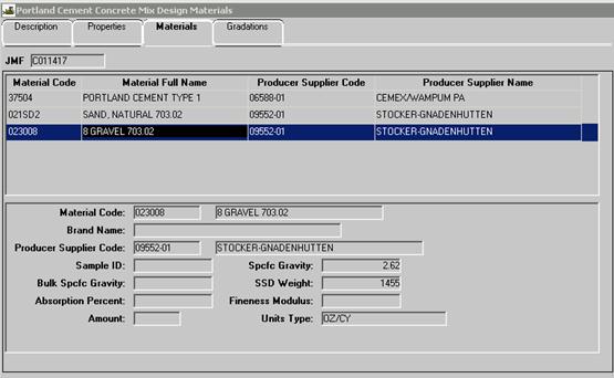
The concrete proportion
section of SiteManager for the JMF
give the quantities of all materials to be used in each cubic yard (cubic
meter) of concrete, depending on what class of concrete and the type of
aggregate is used. The aggregate weights
given in the tables are the saturated surface dry (SSD)
design weights.
See example of SiteManager JMF info below.
If the specific gravities of
the proposed aggregate materials for use on a project vary by more than 0.02 on
the approved aggregate list from the specific gravities shown in the JMF, the Engineer should require adjustment of the table
weights as specified in the JMF. This is done by dividing the SSD design table weight by the design specific gravity
(from the JMF) and multiplying this by the actual
specific gravity that is going to be used on the project. Equation 499.3 shows this calculation:
![]()
Equation
499.3 – Adjusted SSD Design Weight
Where:
![]() = Design Weight (SSD) from
the Job Mix Formula (JMF)
= Design Weight (SSD) from
the Job Mix Formula (JMF)
DSG = Design Specific
Gravity from the JMF
ASG = Actual SSD specific gravity to be used on the project
Adjusted ![]() = Design
Weight (SSD) adjusted for the actual aggregate
specific gravity
= Design
Weight (SSD) adjusted for the actual aggregate
specific gravity
Example:
Class
QC 2 concrete, using natural sand and limestone coarse aggregate, is to be used
on a project. The specific gravity of
the fine aggregate is 2.66 and there is the specific gravity of 2.68 for the
coarse aggregate. Determine the adjusted
SSD design weights of fine and coarse aggregate based
on these specific gravities.
The SSD
design weights and design specific gravities for Class QC 2 concrete in JMF for natural sand and limestone coarse aggregate are:
|
Aggregate Type |
Design Weight (SSD) |
Design Specific Gravity |
|
Fine Aggregate (Nat.
Sand) |
1,240 lbs |
2.62 |
|
Coarse Aggregate
(Limestone) |
1,510 lbs |
2.65 |
The
SSD design weights adjusted for the specific
gravities are calculated as follows:
Fine
Aggregate Adjusted ![]() =
=
![]()
Coarse
Aggregate Adjusted ![]() =
= ![]()
These adjusted aggregate
weights (![]() ) would be further adjusted for
moisture contained in them at the time of use instead of the table weights.
) would be further adjusted for
moisture contained in them at the time of use instead of the table weights.
Absolute
Volume
The material proportions for
concrete mixtures JMF given in pounds (Kg). Any adjustments to the aggregate proportions
must be done using absolute volumes. For
example, the yield of a batch of concrete is required to be accurate within a
tolerance of ± 1 percent at the target (design) air content and slump. If an over- or under-yield is experienced
adjustments in the batch weights need to be made. The Inspector should notify the Engineer and
Contractor of the yield issue. An
adjustment to the proportions needs to be made if the Contractor wants the mix
to stay within tolerance. Based on the
yield calculated by the Inspector or Contractor, it will be necessary to
calculate the weight in pounds
(kilograms) of aggregate required for a certain amount of yield
correction in cubic feet (cubic meters).
Adjustments to correct yield are to be based on the absolute volume.
When the specific gravity of
any material is known, the absolute volume of any weight of that material can
be calculated as shown in Equations 499.4 and 499.5:
![]()
Equation
499.4 – Absolute Volume
![]()
Equation
499.5 – Absolute Volume (metric)
Example:
The
absolute volume of 94 lbs (42.6 kg) of Type 1 cement that has a specific
gravity of 3.15 is:
![]()
![]()
This
calculation shows that 94 lbs (42.6 kg) of cement, which represents 1 cubic
foot of loose volume, has an absolute volume of 0.48 ft³ (0.0135 m³).
Yield Adjustment
using Absolute Volume
To make a yield adjustment, a
volume of over-yield or under-yield is first determined. This absolute volume must be converted to a
weight of material. An absolute volume
of any material can be converted to a weight of that material by using Equations
499.6 and 499.7:
![]()
Equation
499.6 – Weight from Absolute Volume
Where:
AV = absolute volume of the material (ft3)
SG = specific
gravity of the material
62.4 = lbs/ft3
![]()
Equation
499.7 – Weight from Absolute Volume (metric)
Where:
AV = absolute volume (m3)
SG = specific gravity
1,000 = kg/m3
Example:
Calculate
how many pounds (kg) of a coarse aggregate,
with a specific gravity of 2.66, would be required to adjust an under-yield of
0.64 ft³ (0.018 m³). The calculation is
as follows:
Weight (lbs) = (0.64 ft³) x (2.66) x
(62.4 lbs/ft³) = 106.2 lbs
(Weight (kg) = (0.018 m³) x
(2.66) x (1,000 kg/m³) = 47.88 kg)
Thus,
106 lbs per cubic yard (48 kg per cubic meter) of coarse aggregate, with a
specific gravity of 2.66, would have to be added to correct the above
under-yield volume of 0.64 ft³ (0.018 m³).
While
the example shows only a coarse aggregate correction, a correct over- or
under-yield would have all aggregate proportions corrected to make up the yield
different.
If
the aggregate for a mix was:
40%
No. 57 stone
20% No.
8 stone
40%
natural sand
You
would determine the percentage for the under-yield (above):
40%/100
x .64 = .26 ft³ No. 57 stone
20%/100
x .64 = .14 ft³ No. 8 stone
40%/100
x .64 = .26 ft³ natural sand
Then,
calculate (using the above) formal and the specific gravity for each to
determine the amount of materials to be added for each aggregate type.
Moisture Correction
Aggregate can be in one of
four moisture conditions:
1. Oven-dry aggregates are heated until they are
completely dry. There is no moisture
within the aggregate particles or on the surface of the particles.
2. Air-dry aggregate is dry on the surface, but still
contains some water within the aggregate particles. Air-dry aggregate will absorb a small amount
of mixing water if used in concrete.
Aggregate in this condition requires adjustments to the design weights
and adjustment of the batch water.
3. Saturated surface dry (SSD)
aggregate looks damp, but it contains no free water on the surface. The
aggregate particles have completely absorbed all the water possible and do not
contribute water to the batch. The
concrete tables in the JMF give SSD
weights of coarse and fine aggregate, but aggregate in this condition rarely
exists in aggregate stockpiles.
4. Wet (damp) aggregate has water on the particle surface
and shows water sheen. The aggregate particles have absorbed all the
water they can and will contribute water to the concrete mix. Aggregate in this
condition requires adjustments to the design weights and adjustment of the
batch water.
In the field, aggregate used
in concrete will be in a wet (damp) condition or air-dry condition. Aggregate in the SSD
or oven-dry conditions is used by contractors and inspectors to determine
moisture correction factors for use in adjusting the SSD
design weights.
Before concrete can be
batched, the concrete mix SSD design weights shown in
the JMF must be converted to batch weights. This is done by adjusting the design SSD weight of each aggregate and adjusting the amount of
batch water to compensate for the moisture in the aggregates. If all aggregates at the concrete plant were
in the SSD condition, the weights given in the
concrete tables could just be weighed up and incorporated into the concrete
batch and no adjustments to the water would be necessary. Seldom, if ever, will aggregate in the field
be found in the SSD condition.
It is necessary to determine
the amount of total moisture in all aggregate in order to determine the weight
of wet (damp) or air-dry aggregate necessary to give the correct weight of SSD aggregate. This total moisture content is used in the
determination of the water-cement ratio.
For example, if an aggregate is determined to contain 5 percent total
moisture, then each 105 pounds (kilograms) of that aggregate actually consists
of 100 pounds (kilograms) of aggregate and 5 pounds (kilograms) of water. In order to obtain 100 pounds (kilograms) of
aggregate by dry weight, it is necessary to take into account the water that
will be weighed along with the aggregate.
Total Moisture
Correction Factor
The Total Moisture Correction
Factor (TMCF) is a term that is useful in determining
the batch weights from SSD design weights (that have
been corrected for specific gravity).
The TMCF can be determined by a moisture
test. To determine the TMCF use Equation 499.8.
![]()
Equation
499.8 – Total Moisture Correction Factor (TMCF)
Where:
TMCF = Total Moisture
Correction Factor
WW=
Wet weight of the sample
ADW = Air Dry Weight of the
sample
ODW = Oven Dry Weight of the
sample
If the total moisture content
(in percent) has been determined by an aggregate moisture test, use Equation
499.9 to calculate the TMCF:
![]()
Equation
499.9 – Total Moisture Correction Factor (TMCF)
The
total moisture percent is changed to a decimal (by dividing it by 100) and then
added to 1.0000 to get the TMCF. For example, if the total moisture in an
aggregate sample, after testing, is determined to be 5.8 percent, then the TMCF is determined as follows:
![]()
Absorbed Moisture
Correction Factor
Another factor that is useful
to determine the batch weights from SSD weights (that
have been corrected for specific gravity) is the Absorbed Moisture Correction
Factor (AMCF).
This factor can be determined by a test.
It is defined as follows:
![]()
Equation
499.10 – Absorbed Moisture Correction Factor (AMCF)
Where:
AMCF= Absorbed Moisture
Correction Factor
SSDW= Saturated Surface Dry
Weight of the sample
ODW= Oven Dry Weight of the
sample
The percent of absorption of
the fine aggregate and coarse aggregate is obtained from the aggregate reports
furnished by the Laboratory. The percent
of absorption represents the amount of water, expressed as a percentage of its
own dry weight, which an aggregate will absorb.
The water that is absorbed by aggregate is not available as mixing water
in the concrete. Adjustments must be
made in the amount of total allowable mixing water to compensate for the free
water on the aggregate surface.
The percent absorption of any
aggregate can be found on the Office of Materials Management website under
Materials Information, Aggregate, and Specific Gravities List.
The Materials Management
website is listed below:
http://www.dot.state.oh.us/Divisions/ConstructionMgt/Materials/Pages/default.aspx
The percent absorption is on
the far right column of this list. The
sources are listed in alphabetical order.
Once the percent absorption of any aggregate is known, the AMCF can be determined by Equation 499.11:
![]()
Equation
499.11 – AMCF
The percent absorption of the
aggregate is changed to a decimal (by dividing the percentage by 100) and then
it is added to 1.0000 to get the AMCF. For example, if the percent absorption for a
coarse aggregate is 2.22 % then the AMCF is
determined as follows:
![]()
Free Moisture
Correction Factor
The Free Moisture Correction
Factor (FMCF) can be calculated once the TMCF and the AMCF are determined
by using Equation 499.12:
![]()
Equation 499.12 – FMCF
Where:
FMCF= Free Moisture Correction
Factor
TMCF= Total Moisture Correction
Factor
AMCF=Absorbed Moisture
Correction Factor
The FMCF
is used to adjust the corrected SSD design weights of
the coarse aggregate and the fine aggregate from the concrete tables in the JMF’s batch weights that are used to produce a batch of
concrete. The batch weight for any
aggregate is determined by either Equation 499.13 or 499.14:
![]()
Equation
499.13 – Batch Weight method 1
![]()
Equation
499.14 – Batch Weight method 2
Where:
![]() = Design Weight (SSD) from
the concrete table, adjusted for the specific gravity
= Design Weight (SSD) from
the concrete table, adjusted for the specific gravity
FMCF= Free Moisture Correction Factor
TMCF= Total Moisture Correction Factor
AMCF= Absorbed Moisture Correction Factor
Example:
Assume
that the following are the design weights SSD
adjusted for specific gravity for a cubic yard of Class QC 1 concrete:
Cement 600 lbs
SSD Fine Aggregate 1,160 lbs
SSD Coarse
Aggregate 1,735 lbs
Maximum Water 300 lbs
Total
Design Weight 3,795 lbs
Prior to concrete placement,
the total moisture contents of the fine and coarse aggregates are
determined. The fine aggregate has total
moisture of 4.95 percent and the coarse aggregate has total moisture content of
3.25 percent. The absorption of the fine
aggregate is 2.85 percent and the absorption of the coarse aggregate is 2.1
percent. Determine the batch weights
using the above moisture data.
First, determine the TMCF and the AMCF for each
aggregate type using Equations 499.9 and 499.11:
|
Fine
Aggregate TMCF |
|
(Equation
499.9) |
|
|
|
|
|
Fine Aggregate AMCF |
|
(Equation 499.11) |
|
|
|
|
|
Coarse Aggregate TMCF |
|
(Equation 499.9) |
|
|
|
|
|
Coarse Aggregate AMCF |
|
(Equation 499.11) |
|
|
|
|
Next,
use Equation 499.14 to determine the fine and coarse aggregate batch weight:
|
Fine Aggregate Batch
Weight |
|
(Equation 499.14) |
|
|
|
|
|
Coarse
Aggregate Batch Weight |
|
(Equation 499.14) |
|
|
|
|
Next, determine the amount of
water added to the mix by each aggregate.
To determine this weight, subtract the SSD
design weight from the batch weight determined above:
Water in Fine aggregate = 1,184 – 1,160 =
24 lbs
Water
in Coarse aggregate = 1,753 –1,735 = 18 lbs
Next, the mix design weight
of water must be adjusted to determine the batch weight of water. In this example, the fine aggregate and
coarse aggregate would both contribute water (24 lbs and 18 lbs respectively)
to the mix. The batch weight of water is
calculated by subtracting the amount of water added by the aggregate from the
design water weight as follows:
Water
Batch weight = 300 lbs - 24 lbs – 18 lbs = 258 lbs
Once the batch weights of all
the ingredients have been determined, they should add up to the same as the
original design weights. This is a good
check to ensure that no errors were made in the calculations. The batch weights for a cubic yard of
concrete based on the total moistures and the aggregate absorptions given in
this example are:
|
Cement |
600 lbs |
|
SSD Fine Aggregate |
1,184 lbs |
|
SSD Coarse Aggregate 1 |
1,753 lbs |
|
Maximum Water |
258 lbs |
|
Total Batch Weight |
3,795 lbs |
Since the total batch weight
equals the original adjusted SSD design weights in
this example, the mix has been adjusted properly for the moisture in the
aggregates. Even though the maximum
water value in the total batch weight (258 lbs) is different than the original
design weight of water (300 lbs), the net water was not changed. The free moisture in the aggregates will
contribute 42 lbs to the mixing water.
In this example, the w/c ratio was kept the same as the original design.
Job Control Tests
The concrete control
Inspector must perform various field tests to determine whether a concrete
mixture is within specifications for slump, air content, and yield. In QC/QA, these tests have specific
frequency. Yield is not an acceptance
test but may be used to determine additional information where there are
problems. The Inspector is there to
verify the Department receives product which meets the specifications. Moisture testing also has to be performed for
use in the concrete mix design control.
Specification 499.04
requires that concrete quality control QC tests are performed. Tests for total air content and slump may be
made at ready mix and central mix plants for control purposes. These tests are desirable to detect loads
that will not conform to specification requirements before they leave the
plant. Any variances to the JMF should be reported by the plant to the Contractor so
that necessary adjustments can be made in the following batches. This type of testing determines quality and
is the responsibility of the Contractor. When concrete is produced in
accordance with a QC/QA specifications (Items 451,
452,
511),
the formal Contractor additional quality control requirements at the placement
site are required.
Department testing is always
considered quality assurance (QA) to verify that the Contractor provided
product meets specifications.
Unless otherwise directed by
the Engineer, perform any QA tests for pavement on plastic concrete samples
taken from the concrete after it has been placed on the base. In the event excess slump is encountered, it
may be desirable to visually observe the consistency (slump) of the concrete in
the bucket or trucks before deposition to avoid the necessity of costly removal
after it is placed.
Perform QA tests for
structural concrete at the site at the time the concrete is being placed. Normally, concrete may be obtained directly
from the hauling units for testing.
However, when concrete is transferred from the hauling units to the
point of use by means of conveyors or by pumping, the amount of slump and air
may change slightly.
Perform testing at the
required frequency of the specification or at a higher frequency if problems
are noted. Do not perform the QC
testing, but provide QA test results to the Contractor so the Contractor can
make necessary corrections.
There may be occasions where
it is not practical to test concrete samples at the point of placement since
this would interfere with placing operations such as for a pier cap. Usually there is not adequate space for testing. In this situation, the sample could be taken
from the point of placement and tested at a different location. Correlation of test data between point of
test and placement may be necessary to ensure specification material is being
placed. Tests could be conducted on
concrete obtained from the hauling units and allowance made for a change in
slump and air as determined by the comparative tests at the point of placement.
Slump, yield, and entrained
air tests are made by the concrete control Inspector. In addition, it is the Inspector's duty to
make required test cylinders and beams.
Any adjustment of batch weights that may be necessary because of the
routine job control tests must be relayed to the concrete plant for immediate
use. The concrete Inspector must be
familiar with the tests being conducted and should occasionally review the test
procedures to ensure that all tests are properly conducted.
Representative Concrete Samples
When obtaining a sample from
dump trucks, side dump hauling units, or other types of hauling units that do
not discharge by a chute, the contents are first discharged or spread on the
base. Samples are then taken from
several different locations within the load.
When sampling from truck
mixers, truck agitators, end dumps, or other units discharging by a chute, the
sample is obtained at three or more regular intervals throughout the discharge
of the entire batch. Do not sample at
the beginning or end of discharge. Sampling
is done by repeatedly passing a receptacle through the entire discharge stream,
or by diverting the stream so that it discharges into a container. The rate of discharge must be regulated by
the rate of revolution of the drum, and not by the size of the gate opening.
The sample consists of not
less than 1 cubic foot (0.03 cubic meters) when it is used for cylinders and
not less than 1 cubic foot (0.03 cubic meters) per beam. Smaller samples may be permitted for routine
air content and slump test.
The sample is carried to the
place where cylinders and beams are to be molded or where the test is to be
made. The sample is then remixed with a
shovel just enough to ensure uniformity.
The sample must be protected from sunlight and wind during the period
between sampling and testing. The test
must be conducted immediately so that the time between sampling and test
completion is held to a minimum.
Moisture Testing
This test is the
responsibility of the Contractor under QC/QA specification or the concrete
producer when not under QC/QA (499.04) a moisture test is made for each aggregate
size to be used. These tests must be made just prior to the start of concrete
production and are used to adjust the batch weights and to determine the
water-cement ratio. Therefore, moisture tests are required at the start of
production, daily for all major concrete placements, and anytime a sizeable
change occurs in the moisture content of the stockpiles. Moisture tests by
concrete suppliers are often performed using calibrated probes in their
stockpiles. These are acceptable if the
results are accurate. Those results can and should be the used by the Contractor
or supplier to adjust SSD mixes for local moisture
content.
Space is provided on Form
TE-45 for documenting the moisture content test on each aggregate used.
Any appreciable change in the
amount of water added at the mixer must be investigated, additional moisture
tests made, and if necessary, the batch weights adjusted accordingly. Concrete suppliers use of stockpile probes
can help with the variations as they make readings throughout the mix process
Following a heavy rainfall,
periodic moisture tests are necessary until the moisture content becomes
uniform. Slight variations in the mixing
water requirements do not require a moisture test and adjustment. However, it
may become necessary to alter the methods of watering, stocking, and
withdrawing the aggregate to avoid fluctuations in water.
The total percent moisture is
determined by using Equation 499.15:
![]()
Equation
499.15 – Total Percent Moisture
Where:
NWW = Net
Wet Weight of the aggregate sample
NDW= Net
Dry Weight of the aggregate sample
To determine the percentage
of moisture or water in fine or coarse aggregate, place a representative sample
of 5 to 10 pounds (3 to 5 kg) in a pan that has been weighed empty and
determine the wet weight of aggregate and pan.
Place pan and aggregate over a fire, or in an oven, and dry to constant
weight. Subtract the weight of the empty
pan from both the wet and dry weights obtained. The results will be the net wet
weight and the net dry weight. Next,
subtract the net dry weight from the net wet weight, which results in the
moisture content (weight of water) in the wet aggregate sample in pounds
(kilograms). Divide the moisture content
by the net dry weight and multiply by 100 percent to obtain the percent
moisture in the sample.
Example:
Assume
that the following weights are obtained for a sample of aggregate:
Empty
Pan Weight =
1.22 lb (0.553 kg)
Weight
of Wet Aggregate + Pan = 8.68 lb (3.937 kg)
Weight
Dry Aggregate + Pan = 8.44 lb (3.828 kg)
The calculations involved to
determine the moisture content in the sample are:
English
calculation
A. Tare Weight of Pan = 1.22 lbs.
B. Wet Aggregate + Pan Weight = 8.68 lbs.
C. B - A = Wet Aggregate Weight = 8.68 -
1.22 = 7.46 lbs.
D. Dry Aggregate + Pan Weight = 8.44 lbs.
E. D – A = Dry Aggregate Weight = 8.44 –
1.22 = 7.22 lbs.
F. C – E = Weight of Water = 7.46 – 7.22 = 0.24 lbs.
G. (F![]() E) x 100% = (0.24 ÷ 7.22) x 100% = 3.3% moisture
E) x 100% = (0.24 ÷ 7.22) x 100% = 3.3% moisture
Metric
calculation
A. Tare Weight of Pan = 0.553 kg
B. Wet
Aggregate + Pan Weight = 3.937 kg
C. B
- A = Wet Aggregate Weight = 3.937 – 0.553 = 3.384 kg
D. Dry Aggregate + Pan Weight = 3.828 kg
E. D – A = Dry Aggregate Weight = 3.828 –
0.553 = 3.275 kg
F. C – E = Weight of Water = 3.384 – 3.275
= 0.109 kg
G. (F![]() E) x 100% = (0.109 ÷ 3.275) x 100% = 3.3 % moisture
E) x 100% = (0.109 ÷ 3.275) x 100% = 3.3 % moisture
Space is available on the
TE-45 form for documenting the moisture content of the aggregate used.
Control of Mixing
Water
Moisture testing of the
aggregate used in the concrete mix design allows the calculation of the total
amount of mixing water that can be used per cubic yard of concrete. This mixing water limit should not be
exceeded for the batch of concrete.
The field adjustment of slump
to workable limits can be obtained by added water (up to the mixing water
limit) only if the maximum water/cement ratio is not exceeded and the air
content is within specification. The
Contractor and/or the Supplier assume the responsibility and financial loss for
concrete that is rejected because it is outside the specification limits. Therefore, the Contractor/Supplier should
have the right to adjust the amount of mixing water.
All approved JMF concrete mixes maximum water-cementitious (w/cm) ratios
are limited by the accepted JMF:
1. The w/cm ratio is a ratio of the weight of water to
the weight of cementitious materials in a batch of concrete.
For the Department’s work,
cementitious materials include cement, fly ash, ground granulated blast furnace
slag (GGBFS), and micro silica. The maximum w/cm ratio and maximum w/cm ratio
are expressed mathematically by Equation 499.16:
![]()
Equation
499.16 – Maximum w/cm Ratio
The maximum w/cm ratios are
used by the Inspector to determine the maximum allowable water in a concrete
batch. The concrete tables give the
weight of cement and cementitious materials and the maximum allowable w/cm
ratio for a cubic yard (cubic meter) of concrete. The maximum allowable weight of water can be
determined for any of the concrete mixes by using 499.17:
![]()
Equation
499.17 – Maximum Allowable Water Method 2
Where:
MAWW=
Maximum Allowable Water Weight
Max.
w/cm Ratio = Maximum water/cementitious ratio given in the concrete JMF
CMW =
Cementitious Material Weight specified in the JMF
Once the maximum allowable
water weight per cubic yard (cubic meter) is determined for a certain class of
concrete, it is adjusted based on the moisture contained in each aggregate at
the time of use and the moisture that each aggregate will absorb. The batch weight of water is determined by
multiplying the adjusted water weight per cubic yard (cubic meter) by the
number of cubic yards (cubic meters) in the batch.
The Inspector must recognize
the Contractor’s/Supplier’s right to make a change in water to prevent the
possibility of having concrete rejected for excessive slump. Inspectors are still required to record all
adjustments of mixing water and to control slump and yield. If water is added to the concrete truck at
the project site, the amount must be recorded and added to the total batch
weight and used in the calculation of the w/cm ratio to ensure that they are
not exceeded.
The Contractor/Supplier does not
have the right to adjust the water requirements without informing the
Inspector. The Inspector must know when
a change is made and the amount of change in order to control and enforce the
specification requirements. Inspectors
are encouraged to cooperate with the Contractor to effectively control the
mixing water to provide concrete of uniform slump.
The amount of water to be
added to the mix to produce concrete of the proper slump cannot be determined
accurately. Therefore, it is necessary
to rely on past experience with the materials being used to estimate the amount
of water to use at the start of concrete placements.
CAUTION: Additional water may be added if the
estimated quantity of water produces low slump concrete, but excess water
cannot be removed if the slump is in excess of maximum allowed. Estimating water should be on the
conservative side unless relying on recent experience. When the Inspector is not familiar with the
materials being used, it is good practice to choose an amount of water about 5
gallons per cubic yard (25 liters per cubic meter) less than the estimated net
mixing water.
Example:
Determine
the maximum allowable water content for an 8-yd³ load of Class QC 1 with the
following one cubic yard design weights:
Cement 385
lbs
GGBFS 165 lbs
Fine Aggregate 1,310 lbs
Coarse Aggregate 1,670 lbs
Max. w/cm ratio 0.50
First,
determine the maximum allowable water per cubic yard by use of Equation 499.17:
![]()
![]()
![]()
![]()
Since 1 gallon of water
weighs 8.32 lbs, the maximum allowable water per cubic yard can be calculated
as follows:
Gallons of Water = ![]() =
33 gallons
=
33 gallons
Next, to determine the maximum allowable water
for the 8-yd³ batch, multiply the one yd³ allowable water by the size of the
batch:
(275
lbs/yds³) x (8 yds³ /batch) = 2,200 lbs
or
(33
gallons /yd³) x (8 yds³ /batch) = 264 gallons
Therefore, the maximum
allowable water is 2,200 lbs or 264 gallons for the 8-yd³ batch. This 2,200 lbs (or 264 gallons) is the
maximum allowable water; that is, the amount of water that would be adjusted
depending on the moisture contained in the aggregates used in the concrete.
Slump
Slump is a measure of the
workability of the concrete and nominal and maximum slump values are given in
499.03. It is measured by a standard
test in accordance with ASTM C
143. This test is done at the point
of placement.
Slump is controlled by the
amount of water that is batched into the concrete. Slump is increased as water is added to a
batch of concrete. There are chemical
admixtures (Type F and G) that can increase the slump chemically, without the addition
of extra water.
The specifications in Section
499.04
require that the saturated surface dry (SSD)
aggregate weights in the concrete tables be corrected to compensate for the
moisture contained in each aggregate at the time of use. The amount of free water in the aggregate
contributes to slump and to the water-cementitious ratio.
Table 499.03-3 Concrete Slump
(below) shows the nominal slump and maximum slump allowed for certain items of
work. Note that the nominal slump for
any of the listed work items can be increased to 6 inch (150 mm) if a
high-range water-reducing (superplasticizing)
admixture is used in the concrete. The
maximum slump may be increased to 7 inches (180 mm) if high-range
water-reducing (superplasticizing) admixture is used.
|
Type of Work |
Nominal Slump inch (mm)[1] |
Maximum Slump inch (mm)[2] |
|
1 to 3 (25 to 75) |
4 (100) |
|
|
1 to 4 (25 to 100) |
5 (125) |
|
|
|
4 (100) |
|
|
1 to 4 (25 to 100) |
5 (125) |
|
|
[1] This nominal
slump may be increased to 6 inches (150 mm), provided the increase in slump
is achieved by adding a chemical admixture conforming to the requirements of 705.12,
Type F or G. |
||
|
[2] This maximum
slump may be increased to 7 inches (180 mm), provided the increase in slump
is achieved by adding a chemical admixture conforming to the requirements of 705.12,
Type F or G. |
||
Slump Test
Requirements
This test is the
responsibility of the Department except for work under a QC/QA specification,
when it is that of the Contractor. A
slump test using the slump cone will be made each time a set of cylinders is
cast for structures or a set of beams is cast for pavements. Further tests are required as needed to
maintain control of the slump within the limits specified.
Slump requirements apply at
the point of use; therefore, slump must be determined at the work site on
concrete being placed in the forms. When
concrete has to be conveyed by any means (by a concrete pump, concrete
conveyor, or bucket) from the hauling units to the forms where it will be
incorporated into the work, the slump should be determined from concrete
obtained as it is being placed in the forms.
Usually, such tests cannot be conducted properly at the point of use,
but the sample can be obtained and removed to a convenient site for immediate
slump determination. By correlating such
tests with tests on the same concrete being discharged from hauling units
several times a day, the difference in slump can be determined and applied to
all other tests conducted on concrete from the hauling units. In this manner, there will be less
interruption in production and less interference in conducting the tests.
At the ready mix and central
mix plants, loads may be checked for slump so that appropriate adjustments may
be made to avoid shipment and rejection of concrete at the work site. Loads that only slightly exceed the slump
requirements when tested at the plant should not be rejected. However,
adjustment should be considered for subsequent loads to avoid the possibility
of rejecting succeeding loads.
Conducting tests at the plant
does not eliminate the necessity of conducting test at the site. Further tests will be required as the
concrete is being placed.
The specification
requirements for slump vary depending on the type of work being
constructed. Table 499.03-3 lists the
required nominal slump and the maximum slump in inches (millimeters). These slumps are achieved using water and any
required admixture. If the Contractor
wants more slump than specified on Table 499.03-3, a Type F or Type G admixture
may be used, and the nominal slump may be increased to 6 inches (150 mm) and
the maximum slump may be increased to 7 inches (180 mm). The higher slump is allowed regardless of the
type of work.
A retarding admixture (Type B
or D) is required in all concrete if the plastic concrete temperature exceeds
75° F (24° C). The
admixture must be dispensed in accordance with the admixture manufacturer's
recommendations and the water cement ratio must not be exceeded.
Slump must be maintained at
the specified nominal slump, except that an occasional load, exceeding the
nominal range, but within the maximum slump limit, may be used. This is allowed provided an immediate
adjustment is made to reduce the slump of succeeding loads to within the
nominal slump range. Before using concrete
exceeding the nominal slump, the Contractor or supplier must take positive
action to reduce the slump of following loads.
If the high slump was the result of adding too much water at the site,
less water should be added to the next load.
If high slump results from water added at the plant, notify the plant
before using the batch and order an immediate reduction in water. Use of concrete having the slump between
nominal and maximum should be restricted to an occasional load.
Slump Test (ASTM C
143)
Start the slump test within
five minutes of obtaining a composite sample. The inner surface of the slump
cone is dampened and placed on a clean, flat, moist, non-absorbent, rigid
surface, such as a smooth plank.
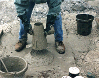
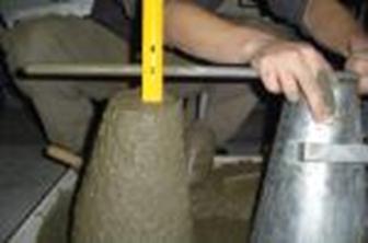
Figure
499.A – Pulling the Slump Cone Vertically from a Prepared Sample
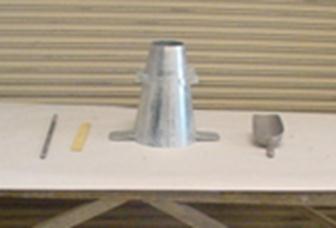
Figure
499.B – Equipment Necessary for the Slump Test- Slump Cone, Tamping Rod, Scoop,
and Ruler
Component Parts and
Accessories
1. Slump cone – A metal mold in the shape of a cone with
an 8-inch ± 1/8-inch (203-mm ±3.2 mm) diameter base, a 4-inch ± 1/8-inch
(102-mm ±3.2 mm) diameter top that is 12 inches tall. The mold must be made of metal no thinner
than 0.045 inch (1.14 mm). The inside
metal surface must be smooth.
2. Accessories
3. Tamping rod – A straight, 5/8-inch (16 mm) diameter
rod that is approximately 24 inches (600 mm) long with a rounded
(hemispherical) tip.
4. Ruler – A ruler or tape to measure the slump of the sample.
5. Scoop – A metal scoop that is used to place the
concrete sample into the slump cone.
Method of Operation
The
Inspector holds the cone firmly in place, while it is being filled, by standing
on the foot pieces.
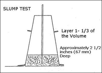
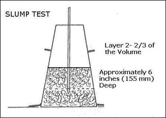
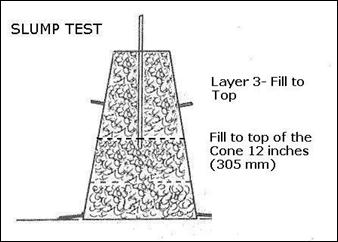
The
mold is filled in three layers, each approximately one-third the volume of the
mold: the first layer approximately 2 1/2 inches (67 mm) deep, the second layer
6 inches (155 mm) deep, and the third layer 12 inches (305 mm) to the top of
the cone.
In placing each scoop of
concrete in the slump cone, the scoop is moved around the top edge of the cone
as the concrete slides from it in order to ensure uniform distribution of
concrete within the cone.
Each layer is rodded 25 strokes with the tamping rod. The strokes are distributed in a uniform
manner over the cross-section of the mold and should penetrate into, but not
through, the underlying layer. The
bottom layer is rodded throughout its depth.
In filling and rodding the
top layer, the concrete is heaped above the mold and any excess is maintained
above the top while rodding. After the
top layer has been rodded, the surface of the
concrete is struck off with the tamping rod so that the mold is exactly filled.
Next, release the foot pegs
while pressing down firmly on the hand holds on the slump cone, while being
careful to keep the cone firmly on the base.
Remove any excess concrete at the base of the slump cone.
Lift the slump cone straight
up in one steady motion. The operation
of raising and removing the mold is performed in 3 to 7 seconds by a steady,
upward lift, with no lateral or twisting motion being imparted to the concrete
sample.
The slump is the distance the
concrete drops from the original height of the sample, which is 12 inches (305
mm). To measure the distance, place the
slump cone beside the slumped concrete and place the tamping bar on top of the
cone so that the bar is level and above the displaced original center of the
sample. Measure the distance from the
displaced original center of the sample to the bottom of the tamping rod. The distance measured is the slump of the
concrete.
Figure
499.C – Measurement of Slump
The entire operation from the
start of filling through mold removal must be completed within the elapsed time
of 2-1/2 minutes. The slump must be
recorded in inches (millimeters) to the nearest 1/4-inch (6 mm). Slump cone test results should be recorded in
the column labeled, "Slump Inches (millimeters)," on the TE-45
Report.
Concrete
Yield
The yield of a concrete batch
is the volume that it occupies. Concrete
is sold by volume, but it is batched by the weight of
each ingredient. This test is not
specifically required for QC/QA specifications.
It is the Contractor’s responsibility.
For non QC/QA concrete, the Inspector should run a QA for each day's
production after the slump and entrained air content have been properly
adjusted. A yield test is then done to
confirm the volume of concrete in the batch.
Yield tests are made whenever
the yield is in doubt, after adjustments are made in the mix, or when cylinders
or beams are cast. Unless the quantity
of concrete to be mixed is small, at least two tests should be made each day.
Yield must be within a
tolerance of ± 1 percent at the design air content and at the specified
slump. Therefore, 1 cubic yard (27
cubic feet) may vary from 26.73 to 27.27 cubic feet per cubic yard (1 cubic
meter may vary from 0.99 to 1.01 cubic meter).
An 8 cubic yard load is 216 cubic feet (8 x 27 cu.ft.
/ cu.yd.).
This load may vary from 213.84 to 218.16 cubic feet (a 7-cubic meter
load may vary from 6.93 to 7.07 cubic meters).
A consistent over- or under-yield, even within the tolerance, should be
corrected in order to maintain the correct cement factor.
Yield Test (ASTM C
138)
The yield is calculated by
performing a field test to determine the unit weight of a representative sample
of concrete taken from the batch. The
Department uses the bottom pot of the pressure meter to determine the unit
weight of a concrete sample. The unit
weight of the concrete is then used to calculate the yield by the following
formula:
![]()
Unit weight is the ratio of
the weight of a material to the volume that it occupies. Unit weight is expressed in pounds per cubic
foot (kilograms per cubic meter).
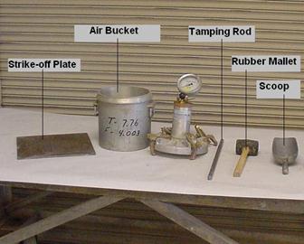
Figure
499.D – Equipment Used for the Yield Test
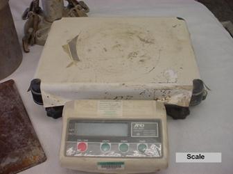
Figure
499.E – Scale Used for the Yield Test
Component Parts and
Accessories
1. A volume measure, a pressure meter air pot at least
0.20 ft³ (0.006 m³.) capacity. The
container volume must be known or an air pot factor must be determined prior to
use.
2.
Accessories
a. Strike-off bar.
b. Scoop.
c. Strike-off plate – A flat square plate at least 2
inches wider than the diameter of the measure and at least 1/4 inch (50 mm)
thick if made of steel and 1/2 inch thick if made of glass.
d. Tamping rod – A straight 5/8-inch (16 mm) diameter
steel rod which is approximately 24 inches (600 mm) long with a rounded
(hemispherical) tip.
e. Scale – A scale of a capacity to weigh the pot filled
with concrete.
f. Rubber mallet, 1.25 ± 0.50 lbs (0.6 kg ± 0.25 kg).
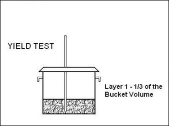
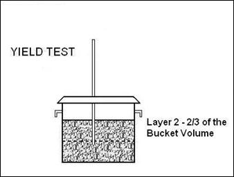
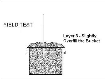
Figure
499.F – Yield Test – Bucket is Filled in Three Equal Layers
Method of Operation
The concrete yield is
determined as follows:
1. To determine the unit weight of a concrete sample,
first weigh the bottom of the empty air pot to the nearest 0.01 pound (0.005
kg).
2. Next, fill the measure with concrete, representative
of that being placed in 3 equal layers, rodding each layer with 25 strokes of
the tamping rod. After rodding each
layer, tap the measure on the sides 10 to 15 times with an appropriate mallet
to close any voids left by the tamping rod and to release any large bubbles of
air that may have been trapped.
3. After the consolidation is completed, strike-off
excess concrete and finish even with the top edge of the measure with the metal
strike-off plate. After strike-off,
clean all excess concrete from the exterior of the measure and determine the
gross weight of the measure and the concrete sample.
4. Calculate the net weight of the concrete sample in
pounds (kilograms) by subtracting the weight of the measure from the gross
weight.
5. The net weight of the concrete sample is then used to
determine the unit weight. The unit
weight is the product of the net weight of the sample under test and the air
pot factor as follows:
![]()
The air pot factor is the
inverse of the volume of the air pot in cubic feet, as shown in Equation
499.20:
![]()
Equation
499.20 – Air Pot Factor
Therefore, an air pot volume
of 1/4 cubic feet or 0.25 cubic feet would have a pot factor as follows:
![]()
Note: The air pot factor is determined by a
Laboratory test and is written on the side of all air pots. This factor is determined by a calibration
process described in the section entitled, Determination of the Air Pot Factor.
When the air pot factor is
multiplied by the net weight of the concrete sample that is consolidated and
struck off into the air pot’s volume (per Equation 499.19), mathematically it
is the same as dividing the net weight of the sample by the volume of the
concrete sample weighed. This gives the
Unit Weight of the sample in pounds per cubic foot (kilograms per cubic meter).
The calculated unit weight of
the concrete is the number of pounds per cubic foot (kilograms per cubic meter)
for the sample under test. The unit
weight is used to calculate the yield.
Next, calculate the yield
using Equation 499.18:
![]()
The total batch weight of the
concrete is the weight of all the ingredients used in the batch or a cubic
yard. This includes cementitious materials, moist coarse and fine aggregate,
water added at the plant, plus any water added at the job site to adjust slump. This total batch weight is divided by the
unit weight of the concrete sample to determine yield. The yield is the number of cubic feet (cubic
meters) of concrete in the batch.
Example:
The
following are the batch weights for an 8-cubic yard (7-cubic meter) load of
concrete, delivered to the project:
|
|
|
English (lbs) |
Metric (kg) |
|
1 |
Cement |
4,800 |
2,492 |
|
2 |
Fine Aggregate |
10,698 |
5,550 |
|
3 |
Coarse Aggregate |
13,229 |
6,868 |
|
4 |
Water |
1,664 |
864 |
|
5 |
Total Batch Weight
(1+2+3+4) |
30,391 lbs |
15,774 kg |
An air
pot with an air pot factor of 4.022 (141.24) is weighed empty and determined to
be 7.98 lbs (3.62 kg). The gross weight
of the air pot and the concrete sample is determined to be 43.52 lbs (19.83
kg). Determine the unit weight of the
sample and the yield of the batch of concrete.
First
determine the net weight of the concrete sample:
Gross
wt. of measure + concrete 43.52 lbs (19.83 kg)
Tare
weight of measure empty -7.98
lbs (- 3.62 kg)
Net
weight of concrete sample 35.54 lbs (16.21 kg)
Now
that the net weight of the sample is known, the unit weight is determined by
the use of Equation 499.19 as follows:
Unit
Weight = ![]()
= 35.54 x 4.022 (16.21 x 141.24)
= 142.94 lbs/ft³ (2289.5 kg/m³)
Next,
determine the yield of the 8-cubic yard (7-cubic meter) load of concrete by
using Equation 499.18 as follows:
![]()
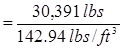
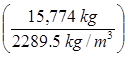
=
212.61 ft³ ![]()
In English units, the
intended number of cubic feet per batch is determined by multiplying the number
of cubic yards in the batch by 27 cubic feet per cubic yard (27 x 8 = 216 = the
intended number of cubic feet per batch).
If the number of cubic feet per batch, as determined by the yield test,
is within 1 percent of the design, at the specified air and slump, no change is
necessary in the batch weights. However,
if the volume of concrete is not within 1 percent of the intended volume, or if
there is a continued over-yield or under-yield even though within 1 percent,
then a yield adjustment must be made. A
yield adjustment involves reducing or increasing the batch weights to correct
an over-yield or under-yield situation.
In the above example, 8 cubic
yards or 216 cubic feet was the intended yield but the calculated yield was
212.61 cubic feet. Therefore, there was
an under-yield of 1.6 %, which exceeds the allowable 1%. To correct this under-yield the batch weights
of the coarse and fine aggregate batch weights must be increased (thus adding
more volume of material to the batch).
Adjustment to correct an over-yield or under-yield should be based on
the absolute volume of dry material.
In Metric units, the yield is
compared to the design number of cubic meters batched to determine if the batch
is within the one percent yield tolerance. The allowable deviation in yield for
a 7 m³ batch is 6.93 m³ to 7.07 m³. In
the above example, the yield was found to be 6.89 m³, which is less than the
allowable range. Again, this under-yield
situation requires an adjustment in the batch weights.
Form C-45, Concrete Control Test Form, is provided for documenting and calculating the tests run in the
field. A copy of this form is shown in
Figure 499.A
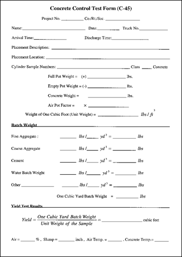
Figure
499.G - Concrete Control Test Form C-45
Making a Yield
Adjustment
Assume the actual calculated
number of cubic feet (cubic meters) per batch is 212.61 cubic feet (6.89 cubic
meters), which is more than 1 percent under the 216-cubic foot (7.0-cubic
meters) intended volume. Therefore, the
batch weights must be increased.
Equation 499.21 shows the calculation of the under-yield:
![]()
Equation
499.21 – Under-yield Calculation
Where:
Percent OY or UY= Percent Over-Yield or Percent Under-Yield
If the number obtained by
Equation 499.19 is a negative number, there is an under-yield and volume must
be added to get the yield back to the intended yield. Conversely, if the number is positive, there
is an over-yield situation and volume must be removed from the batch to reduce
the yield back to the intended yield.
Using the example numbers,
the Percent Under- or Over-Yield can be determined:
Percent OY
or UY =
![]()
![]()
The total batch weight should be increased to adjust
the under-yield. Since the batch of
concrete did not produce the intended volume, additional volume of material
must be added to adjust the under-yield.
Adjustments are made in the fine and coarse aggregate based on absolute
volume. The cement is the minimum specified, and therefore, is not
changed. Water may vary slightly, and
must be considered in making the adjustment. The calculations for adjusting the
mix are as follows:
Total under-yield = 216 ft³ - 212.61 ft³ = 3.39 ft³
(7.00 m³ - 6.89 m³ = 0.11 m³)
Thus, the 8 yd³ (7 m³) load
must be adjusted by adding 3.39 ft³ (0.11 m³) of volume. By adding this much volume to the load, the
yield should increase in subsequent loads after the adjustment is made. The volume needed to adjust the under-yield
is replaced with sand and stone in the same proportion as in the original
concrete sample.
Next, determine the percent
of fine and coarse aggregate in relation to the total aggregate weight in the
original mix design. For this calculation, the corrected SSD
design weights are to be used.
Fine aggregate (SSD) 10,160
lb (5271 kg)
Coarse aggregate (SSD) 12,944
lb (6720
kg)
Total Aggregate (SSD) 23,104 lb (11,991 kg)
% Fine Aggregate =
![]()
![]()
% Coarse Aggregate =
![]()
![]()
Next, determine the
proportion of the 3.39 cu. ft. (0.11 cubic meters) under-yield volume that must
be fine and coarse aggregate. These
adjustments maintain the same proportion of aggregate in the adjusted mix
design as was in the original mix design.
Fine Aggregate = 3.39 ft³ x 0.44 = 1.49 ft³ (= 0.11 m³ x 0.44 = 0.048
m³)
Coarse Aggregate = 3.39 ft³ x 0.56 = 1.90 ft³ (= 0.11 m³ x 0.56 = 0.062 m³)
Total = 3.39 cu. ft³ (= 0.110 m³)
Now that the absolute volume
of fine aggregate and coarse aggregate necessary to correct the under-yield are
known, the weight of each material can be calculated since the specific
gravities of each aggregate are known.
Fine Aggregate Adj =1.49
ft³ x 2.59 x 62.4 lbs/ ft³ (Equation
499.6)
= 241 lbs
= (0.048m³ x 2.59 x 1000 kg/m³)
(Equation 499.7)
= (124 kg)
Coarse Aggregate Adj =1.90
ft³ x 2.63 x 62.4 lbs/ft³ (Equation 499.6)
= 312 lbs
= (0.062 m³ x 2.63 x 1000 kg/m³)
(Equation 499.7)
= (163 kg)
Thus from the above, it can
be seen that 241 lbs (124 kg) of fine aggregate and 312 lbs (163 kg) of coarse
aggregate are required to adjust the yield of this 8-cubic yard (7-cubic meter)
load.
If the mix appears to be
over-sanded, only the coarse aggregate needs to be adjusted. However, if the
mix appears under-sanded, or bony, the adjustment should be in the fine
aggregate only.
The adjustments in the SSD weight of fine and coarse aggregate for the above
example are as follows:
Fine Aggregate 10,160
+ 241 = 10,401 lb (5,271 + 124 = 5,395 kg)
Coarse
Aggregate 12,944 + 312 = 13,256 lb (6,720 + 163 = 6,883 kg)
The new adjusted batch
weights must next be determined, and the water-cement ratio must be checked to
make sure the specified water-cement ratio is not exceeded with the new batch
weights.
Determination of the
Air Pot Factor
This test is done by the
Laboratory or the District Test Lab and is shown here.
The air pot container is
filled with water at room temperature and the top covered with a glass plate to
eliminate all air bubbles and excess water.
Determine the weight of water in the measure to the nearest 0.01-pound
(.005 kg). Measure the temperature of
the water and determine its density from the table below:
Density of Water |
|||
|
English |
Metric |
||
|
Temperature |
Density |
Temperature |
Density |
|
60 |
62.366 |
16 |
999.10 |
|
65 |
62.337 |
18 |
998.64 |
|
70 |
62.301 |
21 |
998.06 |
|
75 |
62.261 |
24 |
997.42 |
|
80 |
62.216 |
27 |
996.70 |
|
85 |
62.166 |
29 |
995.90 |
Calculate the air pot volume
factor by dividing the density of water (from the table) by the weight of water
required to exactly fill the measure.
Measures should be calibrated once each year and the pot factor painted
on the measure. This air pot factor
should be nearly 4.000 (141.24) indicating that the measure is about 0.25 cubic
foot (0.00708 m3) of volume.
Example:
Assume
the temperature of the water used to fill the air pot bottom is 70º F and the
following is determined in the laboratory:
1. Weight of air pot bottom empty plus the glass plate = 8.98 lbs
2. Weight of air pot bottom plus glass plate plus water =
24.47 lbs
3. Weight of water in air pot bottom = (2) - (1) = 15.49
lbs
4. Density of water at 70º F, from the above table = 62.301
lbs/cu.ft.
![]()
Total
Air Tests (ASTM C 231 or ASTM C 173)
The air content of concrete
is measured by a standard test in accordance with either ASTM C 231 (Pressure Meter
Method) or ASTM C 173
(Volumetric Method).
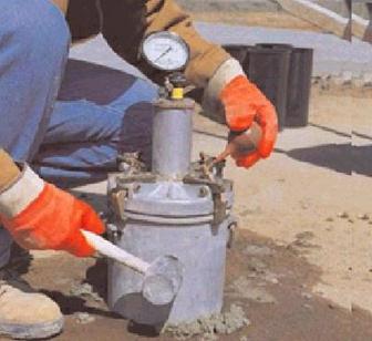
Figure
499.H – Pressure Meter Method
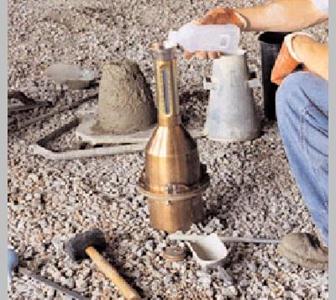
Figure
499.I – Volumetric Method
Air tests must be made for
several loads or batches at the start of daily production and after any
adjustment in the batch weights. A test
is made whenever it is suspected that adequate air entrainment is not being
maintained. An air test must also be
made when a yield test is made and when cylinders or beams are cast.
The requirements apply at the
point of use; therefore, these tests must be made by the concrete control
Inspector at the job site. However, it
may be desirable to check the air content of the concrete at the plant for the
first few batches of the day and also after any adjustment has been made in the
concrete mix design. These checks can
detect deficiencies in air content at the plant where immediate corrections can
be made.
The approximate amount of
entrained air may be determined quickly by using a Chace
Indicator. Every load of transit mix
concrete used in superstructures must be checked for air entrainment. The Chace Indicator
permits a quick check of every load. Its
use also is desirable for all concrete work to quickly check the requirement
for entrained air. Whenever the
specification limits are exceeded according to the Chace
Indicator, a more accurate determination must be made using an air meter
(Pressure Meter or Volumetric Meter).
Make a test from the same batch
of concrete at least once a day using the Chace
Indicator and an air meter to compare the results. Comparison of these results provides the
Inspector with a guide when using the Chace. If the Chace
indicates 4.5 percent and the meter test result is only 4.0 percent, the air
must not be permitted to drop below 4.5 percent when checked using the Chace.
Use a Pressure Meter or
Volumetric Meter to determine the air content to be reported when making yield
tests and when casting cylinders. An
accurate determination is necessary in each case; therefore, an accurate test
is required.
A Chace
Indicator and Volumetric air pot can be used for all types of concrete. The Pressure Meter must not be used when slag
or light weight coarse aggregate are used in the concrete. The Pressure Meter is limited to concrete
consisting of relatively dense coarse aggregate such as gravel or
limestone. A Volumetric Meter test must
be used when slag or lightweight aggregates are used. Detailed explanation of each method follows.
Air Content of
Freshly Mixed Concrete by the Pressure Meter (ASTM C 231)
This test method is used with
dense aggregate concretes for which the aggregate correction factor can be
determined. This method is not
applicable to light weight aggregates, air-cooled blast furnace slag, or
aggregates of high porosity. If these
aggregates are incorporated, a volumetric air test (ASTM C 173) must be used.
This air test measures the
entrapped and entrained air in the concrete sample. The air content from this test is the
apparent air content of the sample. A
separate test is made on the aggregates used to make the concrete to determine
an aggregate correction factor for the concrete aggregates. This percentage value is subtracted from the
apparent air content to obtain the amount of entrained air in the
concrete. Department specifications
specify the amount of entrained air that is required in the concrete at the
point of use.
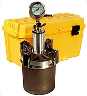
Figure
499.J – Assembled Pressure Meter
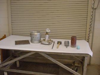
Figure
499.K – Equipment Necessary for Pressure Meter Test
The Pressure Meter Test is
performed as follows:
Parts and
Accessories
1. Component Meter.
a. Pot at least 0.20 ft³ (0.006 m³) capacity.
b. Top, including gauge, pump, and clamps.
2. Accessories.
a. Calibration cylinder.
b. Section of straight tubing.
c. Section of curved tubing.
d. Strike-off bar.
e. 16-mm (5/8") Tamping rod.
f. Rubber syringe.
g. Rubber mallet, 0.6 kg ± 0.25 kg (1.25 ± 0.50 lbs).
h. Wooden carrying case.
Method of Operation
Follow these steps to use a
Pressure Meter to determine the percentage of air in a sample of concrete:
1. Place a representative sample of the concrete in the
bowl in three equal layers, consolidating each layer by 25 strokes of the
tamping rod distributed over the entire cross-section of the bowl. After each layer is rodded,
tap the sides of the measure smartly 10 to 15 times with the rubber mallet to
close any voids left by the tamping rod and to release any large bubbles of air
that may have been trapped. Rod the
bottom layer through its depth, but do not forcibly strike the bottom of the
bowl. When rodding subsequent layers
penetrate the previous layer only about 1 inch (25 mm).
2. Strike off the concrete surface, level full using the
straightedge (or a plate when determining the unit weight), then clean the edge
and exterior of the pot thoroughly.
3. At this point, the pot and sample is weighed. This gross weight is documented for later use
when determining the yield.
4. Next, place the top on the pot and clamp
securely. Close the air valve between
the air chamber and the bowl and open both petcocks.
5. Using the rubber syringe, inject water through one
petcock until all air is expelled through the opposite petcock. Leave petcocks open.
6. With built-in pump, pump up air to the "Initial
Pressure" line on gauge. This
initial pressure line is given on the paper in the carrying case lid.
7. Wait a few seconds for the compressed air to cool to
normal temperature and then stabilize the gauge hand at the proper initial
pressure line by pumping or bleeding off as needed.
8. Close both petcocks and press down on the thumb lever
to release air into the base. Hold thumb lever down for a few seconds. Tap the sides of the bowl several times sharply
with the mallet. Lightly tap the gauge
to stabilize the hand on the dial.
9. Read and record the percent of air entrainment as
shown on the gauge. This is the apparent
air content of the concrete in percent.
10. The true percentage of air-entrained in the concrete
is the apparent air content, as found is in 9 above, minus the aggregate
correction factor as determined is in the following section entitled,
Determination of Aggregate Correction Factor.
Therefore, subtract the aggregate correction factor from the apparent
air content found in 9 and record it on the TE-45
Report as percent of entrained air in concrete.
Determination of
Aggregate Correction Factor
Since aggregate particles
generally are porous, they contain a small amount of volume of air that is
included in the apparent air content, as measured in 9 above. This volume percentage must be deducted from
the total air content percentage to obtain the true entrained air content of
the concrete. To obtain the aggregate
correction factor it is necessary to run an air determination (with the
pressure meter) on equivalent amounts of fine aggregate and each size of coarse
aggregate that would be contained in the air pot volume of concrete. This factor varies with different aggregate
sources and must be determined by actual tests.
The aggregate correction factor is determined prior to any concrete
placement and is applied as long as there is no change in the source of the
aggregate or proportioning used in the concrete under test.
The Aggregate Correction
Factor is determined as follows:
1. The amount of each aggregate to be used in the test is
determined by dividing the volume of the air pot by the intended volume of the
concrete batch. This ratio is multiplied
by the actual batch weight of the particular aggregate that was used in the
concrete. Use equation 499.24 to
determine the weight of each aggregate to be used in the test.
![]()
Equation
499.24 – Weight of each Aggregate
Where:
APV = Air Pot Volume in cubic
feet (m³)
IBV= Intended Batch Volume in
cubic feet (m³)
ABW = Aggregate Batch Weight in
lbs. (kg) for the intended volume
Example:
Given the following
information determine the amount of fine and coarse aggregate necessary for an
aggregate correction test:
Volume of Air Pot = 0.25 ft³ (0.00708 yd³)
Intended Volume of Concrete per Batch = 8 yd³ or 216 ft³
(7 m³)
Aggregate Batch Weight for Fine Aggregate = 10,698 lbs
(5550 kg)
Aggregate Batch Weight for Coarse Aggregate = 13,229 lbs
(6868 kg)
|
Fine
Aggregate Weight |
|
(Equation
499.24) |
|
|
|
|
|
|
(Equation
499.24) |
|
|
|
|
|
|
Coarse
Aggregate Weight |
|
(Equation
499.24) |
|
|
|
|
|
|
(Equation
499.24) |
|
|
|
|
Therefore, 12.38 pounds (5.6
kg) of sand and 15.31 pounds (6.9 kg) of stone are used to determine the
correction factor.
2. Fill the air pot one-third full of water. Carefully add a portion of the coarse
aggregate then a portion of the fine aggregate.
Jar the pot and rod the aggregate to eliminate any entrapped air. Carefully repeat, adding portions of each
aggregate until all the aggregate is inundated into the pot. Each aggregate addition must be added
carefully as instructed in order to get the entire quantity into the volume of
the pot. Make sure that aggregate in the
pot remains submerged at all times. If
the sand is not rodded into the voids between the
coarse aggregate particles, the aggregate quantities will overflow the
pot. Aggregates should be in
approximately the same moisture condition as those used in the concrete.
3. Strike-off any excess foam and keep the aggregates
inundated for a period of time approximately equal to the time between
introduction of water into the mixer at the concrete plant and the time of
performing the air test in the field.
4. Screw the short piece of straight tubing into the
threaded petcock hole on the underside of the top cover. Place the top on the
pot and clamp securely. Close the air
valve between the air chamber and the measuring bowl and open both petcocks.
5. Add water with a syringe through the petcock having
the pipe extension below until all air is expelled from the second
petcock. Leave both petcocks open.
6. Pump up the air pressure in the air chamber to a
little beyond the initial pressure line marked in the carrying case lid. Wait a few seconds for the compressed air to
cool to normal temperature, and then stabilize the gauge at the proper initial
pressure line by pumping or bleeding off air as needed and tapping the gauge
slightly.
7. Screw the curved tube into the outer threaded end of
the petcock. Close both petcocks and
press the thumb lever to release the air into the bowl. Fill the 5 percent calibrating vessel level
full of water from the base by controlling the flow of water with the petcock
valve on the curved tube.
8. Release the air at the free petcock and let the water
in the curved pipe run back into the base. The air meter now has 5 percent of
its volume removed.
9. With both petcocks open, pump the air pressure in the
air chamber to slightly beyond the initial pressure line. Wait for the compressed
air to cool, and then stabilize the gauge hand at the proper initial pressure
line by pumping or bleeding off air as needed and tapping the gauge slightly.
10. Close both petcocks and press the thumb lever to
release the air into the bowl.
11. Read and record the air content shown on the meter.
The aggregate correction factor will be the difference between the air content
on the meter minus 5 percent.
Note: Normally the aggregate
correction factor will be between 0.1 and 0.8 percent. This factor will ordinarily remain constant
(with limestone or gravel coarse aggregate) for the same combination and
quantity of aggregate. It is essential,
therefore, to determine the aggregate correction factor accurately since any
errors made in the factor will be reflected in all air content determinations.
BE SURE THAT ALL AIR ENTRAPPED IN THE INUNDATED AGGREGATE IS ELIMINATED WHEN
PREFORMING THE TEST.
Checking Calibration
of Gauge
All Pressure Meters are
calibrated and tested for leaks. Any
changes found in the manufacturer’s initial pressure line is marked in red on
the paper in the carrying case lid, before the meters are issued by the
Laboratory. However, rough handling or
worn or damaged parts will affect the calibration. Therefore, the operator should check the
meter every 3 months. The method of checking is as follows:
1. Fill the base with water.
2. Screw the short piece of straight tubing in the
threaded peacock hole on the underside of the cover. Clamp cover on the base with the tube
extending down into the water.
3. With both petcocks open, add water with syringe
through the petcock having the pipe extension below, until all air is forced
out of the opposite petcock. Leave both petcocks open.
4. Pump up air pressure to a little beyond initial
pressure line marked in carrying case lid. Wait a few seconds for the
compressed air to cool to normal temperature and then stabilize the gauge hand
at the proper initial pressure line by pumping or bleeding off as needed.
5. Close both petcocks and immediately press down on the
thumb lever exhausting air into the base. Wait a few seconds until the hand is
stabilized. If all the air was eliminated and the initial pressure line was
correctly selected, the gauge should read 0 percent. If two or more tests show
a consistent variation from 0 percent, then change the initial pressure to
compensate for the variation. Use the newly established initial pressure line
for subsequent tests.
6. Screw the curved tube into the outer end of petcock,
and by pressing on the thumb lever and controlling flow with petcock lever,
fill the 5 percent calibrating vessel lever full of water from the base.
7. Release the air at the free petcock. Open the other petcock and let the water in
the curved pipe run back into the base. There is now 5.0 percent air in the
base.
8. With petcocks open, pump air pressure in the exact
manner as outlined in Step 4 above.
Close petcocks and immediately press the thumb lever. Wait a few seconds
for the exhaust air to cool to normal temperature and for the needle to
stabilize. The dial should now read 5.0
percent.
9. If two or more consistent tests show that the gauge
reads less than 4.9 percent or more than 5.1 percent then remove the gauge
glass and reset the dial hand to 5.0 percent by turning the recalibrating screw
located just below and to the right of the center dial.
Air Content of
Freshly Mixed Concrete by Volumetric Method (ASTM C 173 modified for ODOT use)
This test method can be used
on concrete containing any type of coarse aggregate. This method gives the total air content,
which includes both entrapped and entrained air. This method must be used if lightweight
coarse aggregate, air-cooled blast furnace slag coarse aggregate or aggregate
of high porosity is used in the concrete under test.
The method involves taking a
known volume of concrete and breaking it down by washing it with water in a
sealed container. A fixed amount of
water is used to wash the sample of concrete in the container. After the washing, the volume of the sample
and wash water decreases by the volume of air washed from the known volume.
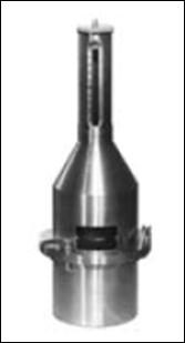
Figure
499.L – Assembled Brass Volumetric Air Meter
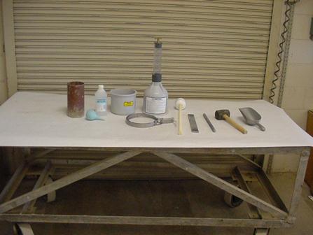
Figure
499.M – Plastic Volumetric Air Meter and Accessories
Parts and
Accessories
1. Meter.
a. Bottom Pot, 0.075 cu. ft. (2.1 L) capacity.
b. Top cone, including gauge glass, clamps and top plug.
2. Accessories.
a. Water filler and dispersion tube.
b. Strike-off bar.
c. 5/8-inch (16 mm) diameter tamping rod.
d. Brass cup capacity 23 milliliter.
e. Small rubber syringe.
f. Can of 70 percent isopropyl alcohol (poison).
g. Rubber mallet 1.25 ± 0.50 lbs (0.6 kg ± 0.25 kg).
h. Carrying case.
Method of Operation
The percent of entrained air
in a sample of concrete is determined as follows using the volumetric air
meter:
1. Place a representative sample of the concrete in the
bowl in two equal layers, consolidating each layer by 25 strokes of the tamping
rod. After each layer is rodded, tap the sides of the
measure 10 to 15 times smartly with the rubber mallet to close any voids left
by the tamping rod and to release any large bubbles of air that may have been
trapped.
2. Strike-off the concrete surface, level full using the
straightedge.
3. Place the cone on the pot and clamp securely.
4. Insert the dispersion tube into the neck of the
meter. Add at least one pint of water
followed by one pint of isopropyl alcohol.
Continue adding water until it appears in the graduated neck of the top
section of the meter. Remove the
dispersion tube. Bring the water level
up until the bottom of the meniscus is even with the 0 mark.
5. Attach and tighten the water-tight cap.
6. Repeatedly invert and agitate the unit for a minimum
of 45 seconds to free the concrete from the base. Do not invert the meter from more than five
seconds at a time.
7. Tilt the meter approximately 45 degrees and vigorously
roll and rock the meter for approximately 1 minute keeping the neck elevated at
all times.
8. Set the meter upright and allow it to stand while the
air rises to the top until the liquid stabilizes. Consider the liquid stabilized when it does
not change more than 0.1 percent within a one-minute period.
9. If the liquid level is obscured by foam, use the
rubber syringe to add sufficient alcohol from a calibrated cup equaling 1
percent of the base’s volume. Record the
number of calibrated cups of alcohol required to disperse the foam.
10. Repeat the rolling and rocking procedure until two
consecutive readings do not differ by more than 1/4 percent.
11. Once the level has stabilized, determine the level of
water in the neck of the meter to the nearest 1/1/4 percent. Add the number of cups of alcohol used to
disperse the foam to the meter reading.
12. Disassemble and empty the contents in the bowl and
examine the bowl to make sure that all of the concrete was dislodged during the
agitating and rolling and rocking procedures.
If there is a significant amount of concrete remaining in the bowl, the
test is invalid and must be redone.
Chace Air
Indicator for Determination of Entrained Air (AASHTO T-199)
This method of test covers
the determination of the air content of freshly mixed concrete by displacing
the air with alcohol and observing the change in level of the liquid in a tube.
The apparatus is light and small, and the test procedure requires only a few
minutes.
This method is satisfactory
for determining the approximate air content of freshly mixed concrete. It
should not, however, be considered suitable for replacing the pressure method)
or volumetric method and in no case should the value obtained through the use
of this method be accepted as determining the compliance of the air content of
concrete with the requirements of specifications. The method is most useful for
determining whether the concrete has a low, medium, or high air content and
whether the air content is reasonably constant from batch to batch of concrete.
Parts and
Accessories
1. Air Indicator.
a. 0.22 cubic inches (3.6 ml) capacity cup.
b. Rubber stopper.
c. Glass top.
2. Accessories.
a. Rubber syringe.
b. Tamping blade.
c. Can of 70 percent isopropyl alcohol (poison).
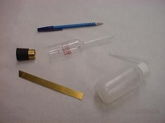
Figure
499.N – Chace Air Indicator Equipment
Method of Operation
The percent of entrained air
in a sample of concrete is determined as follows:
1. Fill the metal cup with cement mortar taken from the
concrete, from which any particles larger than a No. 10 (2.00 mm) sieve have
been removed with the tamping blade. A
No. 10 (2.00 mm) sieve has openings of 0.0787 inches (2 mm) wide or a little less
than 3/32 inches (2.38 mm). Use the tamping blade to pick up mortar. The mortar should not be wet screened to
remove the material larger than a No. 10 (2.00 mm) sieve. Spade material into the cup with tamping
blade to compact the mortar. Strike-off excess
even with top of cup.
2. Hold finger over stem opening of glass top and fill
the glass tube with alcohol to the marked line about 1 inch (25 mm) from the
large end of the glass.
3. Carefully insert cup filled with mortar into the glass
top and turn indicator to a vertical position with the graduated stem up. Be sure stopper is firmly in place. Adjust liquid to top line of stem by adding
alcohol with syringe, making sure that all air bubbles are removed. This can be done by slightly tilting the
indicator.
4. Place finger over the stem opening to prevent liquid
loss. Gently roll the indicator from
vertical to horizontal and back several times until the mortar has been washed
out of the cup.
5. With the indicator in the vertical position, carefully
remove finger from the opening and count the number of spaces from the top line
to the new liquid level estimating to the nearest 0.1. Each space represents 1
percent of entrained air. The air
indicator is designed to read directly for a concrete mix having 15 cubic feet
of mortar per cubic yard (0.56 cubic meters of mortar per cubic meter) of
concrete. Therefore, the air content as
determined by each test must be corrected for mixes with different mortar
content.
6. No conversion factor is used when gravel coarse aggregate
is used in the concrete mix. In this case, the percentage of entrained air is
read directly from the stem. However,
when limestone or slag is used, it is necessary to multiply the stem reading by
1.05 to determine the percentage of entrained air. Record the result to nearest 0.1 percent.

Figure
499.O – Chace Air Indicator
Temperature of Freshly Mixed Portland Cement
Concrete (ASTM C 1064)
Parts and
Accessories
Container – The container
must be large enough to provide at least 3 inches (75 mm) of concrete in all
directions around the sensor of the temperature-measuring device.
Temperature Measuring Device
– The device used must be capable of measuring freshly mixed concrete to ± 1° F
(± 0.5° C) throughout the entire temperature range to be encountered.
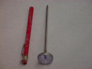
Figure
499.P – Concrete Thermometer
Method of Operation
The temperature of freshly
mixed concrete may be measured in the transporting equipment provided the
sensor of the temperature measuring device has at least 3 inches (75 mm) of
concrete cover in all directions. The temperature is measured as follows:
1. Place the temperature measuring device in the freshly
mixed concrete so that the temperature sensing portion is submerged a minimum of
3 inches (75 mm).
2. Gently press the concrete around the
temperature-measuring device at the surface of the concrete so that the ambient
temperature does not affect the reading.
3. Leave the temperature-measuring device in the
freshly-mixed concrete for a minimum of 2 minutes or until the temperature
reading stabilizes, then read and record the temperature.
4. Complete the temperature measurement within 5 minutes
after obtaining the sample.
5. Report the temperature to the nearest 1°F (0.5 °C)
Gradation of Aggregate
If aggregate is from a
certified source there is no need for further sampling and testing. However a routine sieve analysis can be made
to check compliance with gradation requirements. Gradation can be checked if there are
questions about the concrete you are getting.
If there is an issue, obtain a representative sample and send to the
District Test Lab for evaluation and results.
Making and Handling Concrete Cylinders (ASTM C 31)
The preparation and handling
of concrete test specimens are an important part of the Inspector's duties,
since the cylinders furnish an indication of the quality of the concrete being
produced as the work progresses. Cylinders must be made and handled strictly in
accordance with the following instructions.
On structures over 20-foot
(6.1 m) span, three test cylinders 4
inches (100 mm) in diameter and 8 inches (200 mm) high are made from each 200
cubic yards (150 m³) of each class of concrete, or fraction thereof, incorporated
into the work. On structures of 20-foot
(6.1 m) span or less and bridge deck overlay projects, at least two cylinders
are made for each 50 cubic yards (40 m³) of each class of concrete.
Parts and
Accessories
1. Cylinder molds
2. Scoop
3. 3/8-inch (16 mm) steel tamping rod
The cylinder molds are placed
on a firm, level surface, such as a board, so that the bottoms will not become
deformed in the process of making the cylinders.
Cylinders are always made in
sets of threes from the same batch of concrete.
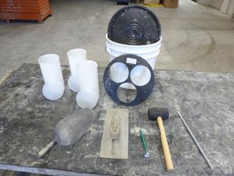
Figure
499.Q – Equipment for Making Concrete Cylinders
Method of Operation
The molding of the specimens
is performed as follows:
1. With the scoop, fill each mold evenly one-half full of
fresh concrete and rod each mold 25 times with the tamping rod, distributing
the strokes evenly over the cross-sectional area of the mold and completely
penetrating the layer of concrete. The
rod should lightly touch the bottom of the mold. Tap the mold lightly 10 to 15 times to close
any air voids left by the tamping rod.
2. Finally, fill the mold to overflowing and rod 25 times
as before. Again, the sides of the mold should be tapped lightly 10 to 15 times
to close any voids left by the tamping rod.
3. Using the tamping rod or trowel, strike-off the excess
concrete flush with the top of the mold. This concludes the operation and there
should be no further manipulation of concrete or mold. Specimens are made in
one continuous operation.
4. After making the three 4-inch x 8-inch cylinders,
place lids on the cylinders.
5. Install the retaining ring with three 4-inch diameter
holes into the curing bucket.
6. Place the cylinders into the curing bucket through the
holes in the retaining ring.
7. In Hot Weather conditions, add water to the
bucket to buffer the cylinders against the heat. Shade the bucket from the sunlight. Pour the water out of the bucket (for weight
purposes) before transporting the cylinders to the lab
8. In Cold Weather conditions, cover the buckets
with thermal blankets, burlap and plastic, etc. to prevent heat loss and
provide a heat source if possible.
9. For projects with a curing box required by 619.02,
carefully move the cylinders in the buckets to curing box after 24 hours. Otherwise, move the bucket to the field
office to maintain samples within appropriate temperatures.
When cylinders are made, the
following tests should also be made using concrete from the same batch:
1. Slump
2. Yield
3. Concrete temperature
4. Air test
Be sure and acquire a
sufficient quantity of concrete to provide for all these tests. Record the test values on the TE-45
Report or directly into a SiteManager sample on test
screens.
- PCC
INSPECTOR DAILY REPORT TE45 PART 1 – BATCH WT
- PCC
INSPECTOR DAILY REPORT TE45 PART 2 – TESTS
Reporting these values from
the same batch as used for casting cylinders provides valuable data for
evaluating compressive strengths of cylinders.
Therefore, always determine slump and air from the same batch of
concrete used in cylinders.
Documentation:
Write the Specimen numbers on
the cylinder molds.
Create a TE-10
tag with the SiteManager sample number and attach
the tag to the handle of the bucket.
Either one TE-31
form describing detailed information on the concrete to be tested or a screen
print from the SiteManager test screen. Put the paper in a plastic envelope and put
the envelope in the bucket.
Concrete cylinders using
ordinary Portland cement concrete mixes are prepared for shipment and sent to
the District Laboratory 48 hours after molding.
If high-early-strength cement is used, cylinders are shipped to the
District laboratory when required by the project but not sooner than 24 hours
after molding
The three cylinders are
packed in a shipping barrel with water and one TE-10
tag is taped before engaging the snap to the ring on the strap on the top of
the case. A filled out copy of a TE-10
tag is shown in Figure 499.B and a filled out copy of a TE-31
form is shown in Figure 499.C.
Cylinder test results will be
reported in SiteManager in PCC
INSPECTOR DAILY REPORT TE45 PART 2 – TESTS screen.
When project concrete
requires, “with QC/QA,” Contractor’s test results only need to be
reported. Make a SiteManager
sample but only complete the PCC INSPECTOR DAILY
REPORT TE45 PART 2 – TESTS screen. Do
not complete the PCC INSPECTOR DAILY REPORT TE45 PART
1 – BATCH WT screen.
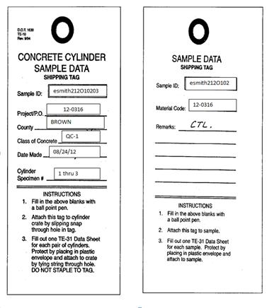
Figure
499.R - Filled Out TE-10 Tags

Figure
499.S - Filled Out SiteManager screen
Making Concrete Test Beams
When required by
specification, the concrete control inspector will make and test concrete beams
as described here, and report the results in the ODOT SiteManager
as explained in Supplement
1023.
Where beam tests are made to
determine when a section of pavement or base may be opened to traffic, two
6-inch x 6-inch x 40-inch (152 mm x 152 mm x 1016 mm) concrete beams are made
using the same concrete being placed in the pavement or base.
Section 511.14
Table 511.14-1b of the specifications requires falsework
for structures to remain in place until the concrete has attained adequate
strength as determined either by the length of curing time or by the testing of
standard concrete beams. When beams are
desirable to determine removal of falsework, they
must be made from the same concrete as that supported by the falsework.
The Laboratory (through the
District Engineer of Tests) will provide the Inspector with the equipment for
making and testing of concrete beams.
Parts and
Accessories
1. 6-inch x 6-inch x 40-inch (152-mm x 152-mm x 1,016-mm)
steel molds
2. Spading tool
3. Trowel
4. Rubber mallet
5. Beam testing machine
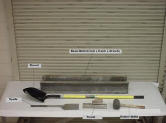
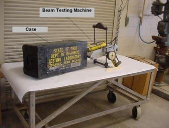
Figure
499.T – Equipment for Beam Testing
Method of Operation
The beams must be made as
described here. Beams must be made and
tested in accordance with Supplement
1023. Steel beam molds must be free
of dirt, hardened concrete, or rust.
They are placed on a smooth, clean, level, and unyielding surface that
has been lightly oiled to prevent the concrete from sticking. The inside of each mold is oiled in the same
manner.
1. Using a shovel, fill each mold half-full with 3 inches
(75 mm) of concrete representative of that in the batch.
2. With the blade of the spading tool held at an angle to
the ends of the mold, spade the concrete 20 times at equal intervals from one
end of the mold to the other.
3. Then, turning the blade of the spading tool,
cross-spade 20 times at equal intervals back in the opposite direction of the
end of the mold.
4. Spade entirely around the side and ends of the mold.
5. Tap along each side of the mold 15 times (total of 30
taps per lift) with the rubber mallet.
6. Fill the mold to overflowing with concrete and repeat
the spading and taping operations as before.
7. Strike-off the excess concrete and trowel the concrete
flush with the top of the beam mold.
8. After concrete is set, the beam numbers are scratched
into the concrete for future identification.
9. Beams must be cured as nearly as possible in the same
manner as the concrete from which they are made.
Pavement beams for 451 and
452 are normally tested at 3, 5, or 7 days of age. If the results are not
needed before the end of the 7-day curing period, only one beam break is necessary
and should be made at the age of 7 days.
The beams must be tested with
the center loading, hydraulic type-testing machine. The load is applied with a
hydraulic jack. The machine scale
reading is a direct reading of the modulus of rupture in pounds per square inch
(megapascals).
Testing Beams with
Center-Loading Hydraulic Type Testing Machine
The hydraulic,
center-loading, beam breaker is designed to test 6-inch x 6-inch x 40-inch
(152-mm x 152-mm x 1,016-mm) concrete beams.
Two flexural strength tests can be made with each beam. The breaker shows a direct read out in pounds
per square inch (megapascals) directly on the
dial. No charts or conversion tables are
needed to change total load to flexural strength, as is the case with other
types of beam breakers now in use. The
standard 6-inch x 6-inch (152-mm x 152-mm) beam is the only size beam on which
this breaker can be used.
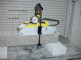
Figure
499.U – Hydraulic Beam Tester in Position on Beam
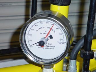
Figure
499.V – Pressure Gauge Dial
Parts and Accessories
1.
Beam Breaker.
a. A main frame with two 7-inch (178 mm) channels
containing two fixed rollers.
b. Yoke assembly containing hydraulic ram, pressure gauge
with four 1/2-inch (114 mm) dial choker valve located just below the gauge, and
center roller.
2. Accessories.
a. Carrying Case.
Method of Operation
The flexural strength, in
pounds per square inch (megapascals) is obtained is
in the following manner:
1. Prepare the beam for testing by rotating it 90 degrees
around the long axis from the position in which it was molded. The original top
of the beam should now be on the side and the top and bottom of the beam should
be the sides of the beam that were originally against the mold. Raise the beam
at least 2 inches (50 mm) off the ground by supporting each end. This allows
clearance under the beam so that the center pin from the yoke of the beam
breaker can be inserted under the beam.
2. Lift the breaker from the carrying case and set it on
the beam to be tested with the two fixed rollers resting firmly on the surface
and one of them about 1 inch (25 mm) from the end.
3. Remove the center roller, a 1-inch (25 mm) round pin
from the two U-shaped clevises by sliding it out. The yoke assembly, containing the ram,
pressure gauge, and choker valve now can be pivoted into the vertical
(operating) position with the clevises extending below the bottom surface of
the beam. There is a stop on one side of
the main frame with which the yoke assembly hinge-bracket must be in contact in
order for the yoke assembly to be in the vertical position. Return the pin to the clevises. The yoke pin
should now be underneath the beam.
4. Close the choker valve (the valve just below the gauge
dial) by turning it in a clockwise direction, when facing the dial, and open it
approximately one-fourth of a turn. Once this valve is adjusted to the position
of one-fourth turn open, this procedure does not need to be repeated with each
test but only if the valve has been inadvertently turned to some other
position. Do not attempt to operate the beam breaker with the choker value
closed.
5. Close the pump valve by turning the pinned extension
valve stem in a clockwise direction.
This valve is located on the right side of the pump when facing the dial
and is opened and closed by an extending through the flange of the aluminum
channel forming the top of the main frame.
This valve must be closed firmly so that the pump will operate properly.
6. Adjust the black hand of the gauge to the zero point
by turning the knurled brass knob on the side of the gauge housing.
7. Set the red hand (maximum indicating hand) near zero
by turning the knurled brass knob in the middle of the plastic dial cover.
8. Operate the pump by slow steady stokes until the beam
breaks or the specified strength plus 100 psi (1.0 mPa)
is reached. Read the flexural strength,
in pounds per square inch (megapascals), as indicated
by the red hand. Unless otherwise required by the specifications, discontinue
the test at 100 psi (1.0 mPa) over the specified
strength in order to avoid unnecessary damage to the beam breaker and note on
the report that the test was terminated before failure.
9. Open the pump valve and the pump plunger will retract
so that the center roller can be withdrawn and the broken portions of the beam
can be removed. If additional tests are
to be made immediately, repeat the foregoing procedure.
10. If no more tests are to be made immediately, the yoke
assembly should be folded down into the horizontal (carrying) position and the
center roller again inserted through the clevises in the preparation for
storage. Then place the beam breaker in
the carrying case.
Recording Results
Record the slump, air
content, concrete temperature, and concrete yield on the TE-45
or TE-45 Supplement form. Record all
beam tests results on the TE-45
later after they are tested and enter them in SiteManager
as detailed in Supplement
1023.
Care and Maintenance of Concrete Testing Equipment
Testing equipment represents
a considerable monetary investment by the Department and therefore, it is
essential that the equipment be given proper care to avoid damage. The equipment has been provided for testing
purposes and must be used in the appropriately to avoid unnecessary abuse or
damage. Periodic review of test
procedures is desirable not only to ensure accurate and uniform testing but to
prevent damage by improper use of equipment.
The equipment is subject to
wear and will need repair and replacement of parts at times. When this repair work is needed, the piece of
equipment should be sent to the District laboratory at once. Equipment must be in good working condition in
order to provide test results that are representative of the material being
tested. In addition, with the volume of
work in progress, it is vital that testing equipment be repaired quickly and
returned to the project in order to provide the equipment necessary for job
control. If this cannot be accomplished,
the Engineer must make arrangements for temporary use of other equipment rather
than omit any required tests.
All equipment must be
thoroughly cleaned immediately after use, being especially sure that all
concrete and mortar is removed from around gaskets, seals, and moving
parts. Thorough cleaning will prevent
build-up of hardened concrete that can affect the operation of the equipment as
well as the test results.
Pressure Meter
When the top assembly is
removed, it should be placed on a clean surface to prevent damaging the gasket
and any earth or fresh concrete from clogging the clamping mechanisms. All fresh concrete should be removed from all
parts of the meter to facilitate its accuracy and continue its efficient
service.
Volumetric Air Meter
The volumetric meter should
not be rolled, rocked, or bumped on hardened concrete, stone, or steel. It should be used on a clean board or
sack. When the top cone is removed, it
should be placed on a clean surface to prevent earth or fresh concrete from
clogging the springs around the fasteners.
The inside of the glass tube should be kept clean of cement particles so
as not to obscure readings. All fresh
concrete should be removed from all parts of the meter to facilitate its
accuracy and continue its efficient service.
Chace Air
Indicator
When emptying the instrument
at the completion of a test, flush out particles of sand from between the glass
and cup to prevent damage when removing stopper. This can be done by holding the indicator
with stem end down, finger over stem, and opening and shaking gently. Carefully
remove stopper and wash and clean the indicator with clean water. Keep the equipment in protective container
when not in use. Should the glass be
broken, the remainder of the set should be returned to the Laboratory for
repair.
Center Loading
Hydraulic-Type Beam Testing Machine
This beam breaker is a piece
of testing equipment and should be handled and cared for like any other
precision instrument. The following
precautionary measures will help keep the breaker in proper operating
condition:
1. Be sure that the choker is open one-fourth turn before
applying load.
2. Do not operate beyond the maximum point indicated on
the dial.
3. Store in the carrying case when not in operation.
4. Remove curing membrane, rust, etc., from the center
roller so that it will fit in the devices easily.
5. Keep thin film of oil on steel parts to prevent rust.
6. Make frequent checks for worn places or breaks in the
rubber hose. Do not operate the breaker with worn or damaged hose. This beam
breaker is actuated by a high-pressure hydraulic system and might be unsafe if
operated with worn or damaged parts.
7. DO NOT ATTEMPT TO REPAIR THE BEAM BREAKER IN THE
FIELD. Return the beam breaker to the Laboratory for any repairs or adjustments
that may be necessary.
Concrete Mix
Adjustments (499.04)
During concrete production
and placement, the Contractor is responsible for adjusting the yield of the
concrete mix design. While a contractor
and the supplier are responsible for adjustments, the concrete control inspector
is responsible for ensuring the Department’s contract is met. There will be times were the concrete control
inspector must validate and therefore understand what affects the yield so that
the yield can be maintained within a certain tolerance. ASTM establishes and industry standard for
yield tolerance of ±1.0 percent.
Verifying the
Yield
As discussed earlier, the
yield of a concrete mix is the volume occupied by the mix. The concrete is designed to occupy a given
volume. Concrete is batched
by weight (not volume) so monitoring the volume (yield) after batching is of
extreme importance. Control of yield is the Contractor and supplier
responsibility. Verification of yield by the Department is done to check that
the truly reflect what has been added or not added into the concrete
batch.
Relative Yield
The term relative yield is
used to understand the effects on yield.
The relative yield of a concrete mix is defined as the one cubic yard
(one cubic meter) batch weight divided by the one cubic yard (one cubic meter)
unit weight of a representative sample of the concrete, as shown in Figure
499.25:
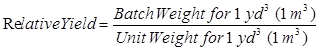
Equation
499.25 – Relative Yield Method 1
Another way to calculate the
relative yield is to divide the actual yield by the intended yield, as shown in
Equation 499.26:
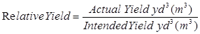
Equation
499.26 – Relative Yield Method 2
The relative yield is a
dimensionless number (it has no units).
When working with relative yield, it is less confusing to include [yd³]
or [ft³] ([m³]) in brackets so the units are not mixed. A relative yield expressed in [yd³] is
multiplied by 27 ft³/yd³ to change it to the number of cubic feet [ft³] of
relative yield.
A relative yield of less than
1.00 is an under-yield and a relative yield of greater than 1.00 is an
over-yield.
Example:
An
8-cubic yard batch of concrete has the following batch weights:
Coarse Aggregate 13,328
lbs
Fine Aggregate 9,448 lbs
Cement 5,080 lbs
Water 2,400 lbs
Total Batch Weight 30,256
lbs
The result of a unit weight
test performed on a concrete sample is 141.35 lbs/ft³. Determine the yield and relative yield of the
batch.
First, the yield can be
calculated from the data given:
|
Yield |
|
(Equation 499.2) |
|
|
|
|
Next, determine the one cubic
yard batch weight:
|
Batch Weight for 1 yd. |
|
(Equation 499.2) |
|
|
|
|
The unit weight for one cubic
yard is determined using the unit weight given:
Unit Weight for 1 yd³ = (141.35 lbs/ft³) x (27 ft³/yd³) =
3816.45 lbs/yd³
Note that in the above calculation,
the 1-cubic yard unit weight is determined by multiplying the 1-cubic foot unit
weight by the conversion factor of 27 ft³/yd³.
This converts the unit weight to lbs/yd³ instead of lbs/ft³.
Now, the relative yield can
be determined by the use of Equation 499.25 as follows:
|
Relative Yield |
|
(Equation 499.25) |
|
|
|
|
Another way to calculate the relative
yield is to divide the actual yield by the intended yield (Equation 499.27):
|
Relative Yield |
|
(Equation 499.26) |
|
|
|
|
In the above calculation, the
actual yield (in cubic feet) is divided by a conversion factor of 27 ft³/yd³ to
convert the actual yield in cubic feet to cubic yards.
The relative yield expressed
in cubic feet is:
Relative
Yield = 0.991 [yd³] x 27 ft³/yd³
= 26.76 [ft³]
In the above example, the
relative yield is less than 1.000 [yd³] or 27.00 [ft³], therefore, there is an
under-yield. The amount of the
under-yield can be determined as follows:
Under-Yield = 0.991 – 1.00
= -0.009 [yd³]
or
Under-Yield = 26.76 – 27.00
= - 0.24 [ft³]
The negative sign indicated
that there is an under-yield. A positive
number would have indicated an over-yield.
The under-yield expressed as
a percent is determined by multiplying the amount of the under-yield in decimal
form by 100 percent as follows:
Under-yield
(%) = -0.009 x 100 %
= -0.9 %
Cement or Cementatious Factor
The cement factor is defined
as the weight of cement in a cubic yard (cubic meter) of concrete, based on the
concrete’s yield. The cement factor is
expressed as the number of pounds of cement per cubic yard (kilograms of cement
per cubic meter).
If the concrete is
over-yielding, the cement that was batched into the load is spread over a
greater volume of concrete than intended by the mix design. If this happens, the cement factor is less
per cubic yard (cubic meter) than intended.
The opposite is true if there is an under-yield. In the case of an under-yield situation, the
cement that was batched into the load is concentrated into less volume than for
which it was designed. In this
situation, the cement factor is greater per cubic yard (cubic meter) than was
intended by the design.
The relative yield is used to
determine the cement factor as shown in Equations 499.27 and 499.27M:
![]()
Equation
499.27 – Cement Factor
![]()
Equation
499.27M – Cement Factor (metric)
The cement weight in the
above equations is the amount of cement intended to be in a cubic yard (cubic
meter) of concrete.
In the above example, the
relative yield was 0.991 and the cement content was 635 lbs per cubic yard
(5080 lbs / 8 cubic yards = 635 lbs/yd³), therefore, the cement factor is:
![]()
(Equation 499.27)
As shown by the above
calculation, the under- yield resulted in a cement factor of 641 lbs per cubic
yard instead of 635 lbs per cubic yard.
The cement factor can
influence the strength of the concrete. An excessive over-yield results in less
cement per cubic yard (cubic meter), as the cement factor
will be less than intended. This could
result in less strength than expected from the batch. An excessive under- yield results in a higher
cement factor, and therefore, higher strength than anticipated. There should not be a noticeable effect on
strength if the yield is maintained within 1 percent of the design as required
by 499.03
of the specifications.
Air Content Effects
on Yield
Air content in concrete has a
significant effect on the yield. Air
content in a concrete mix has no weight but does contribute volume. The air content used in the design is the
target air content. At the target air
content, the yield should be within the tolerance of ±1.0 percent as specified
in 499.03
of the specifications.
If the Inspector determines
the yield problem is the result of an air content that is higher or lower than
the target air content before a mix adjustment is made. There is a way to compute what the relative
yield of a concrete batch would be at an air content that is different from the
tested air content.
First, determine the relative
yield and the tested air content of a concrete sample. Next, compute the non-air portion of the
mix. The non-air portion of the mix is
the volume of all of the component materials except air. This value is determined by multiplying the
actual relative yield by the actual non-air decimal. Once the non-air volume is determined, the relative
yield at any other air content can be calculated. Equation 499.29 is used to determine the
relative yield at a different “target air” content:
Relative Yield at a Target Air
= ![]()
Equation
499.28 – Relative Yield at Target Air
Where:
RY actual = actual relative
yield (yd³)
NAD actual = actual non-air
decimal
NAD target = target non-air
decimal
Example:
As
an example, the relative yield of a concrete mix is found to be 0.974 [yd³] and
there is 4.2% percent air content. What
is the relative yield at 6% percent air content?
The
actual non-air portion of the mix at 4.2% percent air content is 95.8 percent
(100% - 4.2% = 95.8%) of the total volume.
The actual non-air decimal then is 0.958 (95.8%). To calculate the relative yield at 6% percent
air, the target non-air portion of the mix would be 94 percent (100% - 6 % = 94
%) of the total volume. The target non-air decimal is 0.94 in decimal
form. Now the relative yield at 6
percent% air can be calculated as follows:
![]()
Equation 499.28
The calculations show that by
increasing the air content of the concrete from 4.2% percent air to 6% percent
air, the relative yield changes from 0.974 [yd³] to 0.993 [yd³]. The Inspector should not adjust the batch
weights to correct the yield to within ±1.0 %percent but should direct the
Contractor to increase the air content percentage in subsequent concrete loads
to bring the concrete to the proper yield.
The air content affects the
unit weight of the concrete. When the air content percentage in the concrete is
increased, the unit weight of the concrete is decreased. This is due to the increased volume of air
bubbles within the mortal fraction of the concrete volume. This lower unit weight results in raising the
yield higher than it was at the lower air content, assuming the batch weights
are identical. When the yield is
calculated, the same batch weight is divided by a lower unit weight, so the
yield increases.
Adjusting Yield
The concrete control
inspector should not make adjustments in the mix design. Mix design adjustments are the responsibility
of the Contractor and the supplier. If
during quality assurance inspections the concrete control inspector finds the
concrete is out of tolerance, notify the Contractor and require adjustments be
made before acceptance of the concrete.
Mix design adjustments should
not be made every time high or low air content affects the yield, because when
the air content is at the target air, the yield will be off. The specifications typically allow air
content to deviate ±2 percent% from the target air content. For all Department mix designs, the desired
yield should be established at the target air content. Once the mix design is adjusted to yield
properly at the target air content, future mix design adjustments are rarely
needed.
To adjust the mix design to
correct the yield, the adjustment is always made in the aggregate weight by
adding or subtracting material. The adjustment
is made by volume, and the volume of the adjustment is converted to a weight of
coarse and fine aggregate proportionately.
Modifying Mix Designs
It may be necessary to modify
an existing concrete mix design while under production. The Contractor accepted JMF
mix designs are designed to produce one cubic yard or 27 cubic feet per cubic
yard (one cubic meter) of concrete.
During production, it may be necessary to change the quantity of a
material in the mix due to specific gravity changes for that material. Adjustments for a change in the actual
aggregate sources are not allowed unless the new the JMF
has been modified to show the new aggregate and the JMF
has been approved.
The yield must be maintained
if a component material’s specific gravity is changed. Specific gravity changes do not change the
volume of the material in the mix design, but they will change the weight of
the material in the mix design.
If of one material is
changed, then the volume of another material must be adjusted to compensate for
the volume change made. If any volume is
added or removed from the design volume, an equivalent volume must be removed
or added respectively to maintain the yield.
Modifying Aggregate
Proportions
Section 499.04
does provide for the Contractor to adjust SSD
aggregate proportions up to 100 lbs (44 kg) per cubic yard (cubic meter). This may be necessary to improve the finishing
characteristics of the concrete, to ensure a workable mix within the slump
range, or to control the yield. These
modifications made in the aggregate proportions are not to change the total
weight of aggregate specified per cubic yard (cubic meter), except for the
following reasons.
1. To correct the SSD aggregate
weights to compensate for the moisture contained in the aggregates at the time
they are used.
2. If it is not possible to make concrete of the proper
consistency without exceeding the specified water-cement ratio, the Contractor
must either use a water-reducing admixture or increase the cement content. If cement is added to the concrete, the
absolute volume of aggregate must be adjusted by the amount of cement absolute
volume added. There is no compensation
to the Contractor for the use of an admixture or additional cement.
3. If at any time the specific gravity of the aggregate
being used changes by more than 0.02 from the specific gravity specified in the
JMF, the design weights need to be adjusted to
conform to the new specific gravity.
4. To adjust the batch weights based on the yield
determined from field tests at the work site.
Maintain the cement content within ±1 percent and do not exceed the
water-cement ratio specified.
It may be necessary or
required by specifications to add an intermediate-size coarse aggregate. If it is necessary to add a quantity of
aggregate, the yield will change unless an adjustment is made to offset the volume
added to the concrete. The same thing is
true if it is necessary to remove a component material from the original mix
design. If any volume of material is
removed, the same volume must be added to the concrete mix to adjust the yield
for the volume removed. The following
example illustrates how a volume change is made.
Example:
To improve the finishing
characteristics of a Class QC 2 concrete using limestone coarse aggregate, it
is decided to remove 100 lbs of coarse aggregate from the following original SSD mix design:
Cement 700
lbs
Coarse Aggregate 1530
lbs, (Specific Gravity = 2.65)
Fine Aggregate 1260 lbs, (Specific Gravity
= 2.62)
Water 350
lbs
What is the new SSD mix design if 100 lbs of coarse aggregate is
removed? Make the volume adjustment by
adding fine aggregate without affecting the yield of the mix.
The new amount of coarse
aggregate is 1,430 lbs (1,530 – 100 = 1,430).
The absolute volume of 100 lbs of this coarse aggregate removed from the
concrete is:
|
Absolute Volume |
|
(Equation 499.4) |
|
|
|
|
Since 100 lbs of coarse
aggregate is removed, the volume is decreased by 0.60 ft³. In order to maintain the yield, 0.60 ft³ of
fine aggregate must be added. This
volume is used to calculate the weight of fine aggregate necessary to be added
to maintain the original yield as follows:
|
Addition of Fine Aggregate |
|
(Equation 499.6) |
|
|
= 98 lbs |
|
This calculation shows that
98 lbs of fine aggregate (of specific gravity 2.62) must be added to offset the
100 lbs of coarse aggregate (of specific gravity 2.65) removed from the mix
design. The new fine aggregate SSD design weight
becomes 1,358 lbs (1,260 + 98 = 1,358).
Therefore, the following is
the new SSD mix design:
Cement 700
lbs
Coarse Aggregate 1,430
lbs, Specific Gravity = 2.65
Fine Aggregate 1,358 lbs, Specific Gravity
= 2.62
Water 350
lbs
Note that the specific
gravities of the coarse and fine aggregates are similar; therefore, the
difference in the weight between the coarse aggregate removed and the fine
aggregate added is only 2 lbs.
Modifying the Slump
It may be necessary to
increase the slump of the concrete by adding water to the mix design, or reduce
the slump by removing water from the mix design. With the addition or removal of water from a
mix design, both the water-cement ratio and the yield will change.
If the concrete in use is
being batched at the maximum water-cement ratio, no additional water is
permitted, or the water-cement ratio would be exceeded. It may be necessary to add cement, to
maintain the water-cement ratio. Only allow this type of modification after
approval of the Engineer. If allowed,
the follow example defines the method to determine the additional cement.
Example:
A concrete mix has a
water-cement ratio of 0.50 and the slump is 2 inches at the maximum allowable
water. It is decided to add 10 lbs of
water to the mix design to increase the slump.
Determine the amount of cement necessary to maintain the 0.50
water-cement ratio. Determine the amount
of volume added due to the addition of the 10 lbs of water and this necessary
amount of cement.
Since the water-cement ratio
is defined as follows (Equation 499.13):
![]()
The following form of
Equation 499.13 calculates the weight of cement from the w/cm ratio:
![]()
Equation
499.29 – Cement Weight from w/cm Ratio
Therefore, the amount of
cement necessary is:
|
Weight of Cement |
|
(Equation 499.29) |
|
|
|
|
To
maintain the yield, a volume adjustment must be made for both the 10 lbs of
water and the 20 lbs of cement as follows:
|
Volume of Water Added |
|
(Equation 499.4) |
|
|
|
|
|
Volume of Cement Added |
|
(Equation 499.4) |
|
|
|
|
The total added volume due to
the water and cement is 0.26 ft ³ (0.16 + 0.10 =
0.26) in this example. In order to
maintain the yield, 0.26 ft³ of aggregate must be removed from the design. Aggregate removed will be proportional to the
aggregate in the mix. If the coarse
aggregate is 60 percent% and the fine aggregate is 40 percent% (and the
specific gravity of the aggregates are the same), the volume of coarse
aggregate removed would be 0,60 x 0.26
ft³ = 0.16 ft³. Fine aggregate would be
0.26 ft³ - 0.16 ft³ = = 0.10 ft³.
Modification of
Aggregate Specific Gravity
If there is specific gravity
changes in the aggregates used, the yield of the concrete mix will change. If there is a specific gravity increase, then
the volume occupied by the same weight of aggregate will decrease and there
will be an under- yield. If there is a
specific gravity decrease, the volume of the same weight of aggregate increases
and the mix will over-yield.
Example:
A concrete mix contains 1,735
lbs of a crushed limestone with specific gravity of 2.65. The aggregate stockpile is depleted and the
Contractor changes to natural gravel coarse aggregate with a 2.57 specific
gravity. Adjust the 1,735 lbs to the new
specific gravity and show how this would affect the yield.
Determine the original volume
in the mix design:
|
Original Mix Design
Volume |
|
(Equation 499.4) |
|
|
|
|
If
the specific gravity changes to 2.57, this same weight of aggregate would have the
following absolute volume:
|
New
Mix Volume |
|
(Equation
499.4) |
|
|
|
|
These calculations show that
same weight of a lower specific gravity aggregate has a greater volume and
would result in an over-yield. To
correct the over-yield the original volume is used to determine how much weight
of the new, lower specific gravity aggregate to use:
|
New Aggregate Weight |
|
(Equation 499.6) |
|
|
|
|
In summary with the lower
specific gravity, the weight decreased from 1,735 lbs to 1,683 lbs per cubic
yard.
Use Equation 499.30 to
calculate a weight adjustment due to a specific gravity change:

Equation 499.30 –
Weight Adjustment due to Specific Gravity Change
Where:
![]() = Original
weight of aggregate (at the original specific gravity)
= Original
weight of aggregate (at the original specific gravity)
![]() = Original specific gravity of the aggregate
= Original specific gravity of the aggregate
![]() = New specific
gravity of the aggregate to be used
= New specific
gravity of the aggregate to be used
For the above example, the
calculation is as follows:
|
New
Weight = |
(Equation
499.30) |
Equipment for Batching and Mixing Concrete (499.05)
Batching
Plants (499.05.A)
The various materials for
each batch of concrete are proportioned at a batch plant. Batch plants may be classified as:
1. Portable or stationary
2. Manual, semi-automatic, or automatic
3. One or two stop
4. Separate or accumulative weighing
These classifications are
dependent on the mobility and the method of weighing and discharging. Batch plants used on the project site usually
are portable and may be moved from job to job. They may be manual,
semi-automatic, or automatic with the latter two categories most common. If all
materials for a batch are discharged at the same point, it is a one-stop
plant. A two-stop plant is a plant where
two stops of the truck mixer is required.
Portable plants are moved
from site to site to reduce the length of haul to the placing site. Stationary
plants usually are used at commercial ready-mix or central-mix plants. Central-mix plants used for concrete paving
are set up at the job site, and, therefore, are portable.
Plants may employ
accumulative weighing for the coarse and fine aggregate; however, separate
weighing devices must be used for weighing cement. Accumulative weighing permits the weighing of
coarse aggregate and then the fine aggregate, using the same hopper and
scale. The predetermined weights for the
two materials are set on the scale for the cut-off. Cement must be weighed separately on a
separate scale and hopper, regardless of how the aggregate is weighed.
For manual plants, each
material is weighed and discharged by manually pulling levels to open and close
gates. In semi-automatic plants, these
gates are operated through electronic controls to open and close at the touch
of a button. If the electric controls
are interlocked, and the completion of one weighing signals the start of next
weighing, etc. and the whole cycle, if weighing and discharging is interlocked
completely, the plant is classed as automatic.
Automatic plants are coming
into widespread use with many being computerized. Some plants use punched cards which have the
weights of the materials represented by holes punched in the card. The size of the batch is dialed by a selector
knob, the punched card is placed into the control panel, and a button is
pressed to start the cycle. Materials
for the batch size selected are automatically weighed and discharged.
A system of interlocks prevents
a batch from being discharged that does not contain the correct amount of each
material. All automatic plants have this
feature. This prevents incorrect batches
in the event that an aggregate bin becomes empty or other trouble develops
which would tend to result in incorrect batch weights. Most automatic plants may be operated
manually or semi-automatically, which permits production in case of an
electronic failure.
The accuracy of the weighing
mechanisms used to weigh each component in the concrete is specified in 499.06. These weighing tolerances are shown below:
|
Weighing Tolerances |
|
|
Item |
Weighing
Tolerance* (Percent) |
|
Cement |
± 0.5 |
|
Fly
ash |
± 0.5 |
|
GGBFS |
± 0.5 |
|
Micro
silica |
± 0.5 |
|
Coarse
aggregate |
± 0.5 |
|
Fine
aggregate |
± 0.5 |
|
Water |
± 1.0 |
|
Admixtures |
± 3.0 |
*
Weighing tolerances apply throughout the range of use.
Prior to use of a concrete
plant, make an inspection to assure that all requirements of the specifications
are fulfilled and that scales meet the batching tolerances specified. This inspection includes checking:
1. Plant bins for adequate partitions to prevent
intermingling of materials.
2. All weighing and metering devices to assure ensure
that their accuracy has been attested to within a 12-month period immediately
prior to use by one of the following methods:
a. By a Sealer of Weights and Measures.
b. By a Scale Servicing Company.
c. By a Certificate of Performance issued by the National
Ready Mixed Concrete Association.
3. The plant must maintain ten 50-pound (23 kg) standard
test weights or the services of a scale servicing company for testing weighing
devices for accuracy. The ten 50-pound
(23 kg) test weights must be sealed within a 3-year period by the Ohio Department of Agriculture. If the service of a scale servicing company
is used, these weights will not be required; however, all weights used in
testing by the Scale Servicing Company must conform.
4. Water meters for accuracy.
5. That a separate weighing device is used for weighing
cement.
6. Admixture dispensers to assure proper dosage will be
used.
If a Certificate of
Performance has been issued by the National Ready Mixed Concrete
Association, the weighing and metering devices will not require checking
for accuracy and the concrete batch facilities may be approved. The certification from the National Ready
Mixed Concrete Association must be within a 6-month period prior to use and
must certify that the plant's weighing and metering devices do meet 499
batching tolerances.
Plant bins are checked for
holes in partitions and to see that separator plates are extended high enough
to prevent spillage of materials when the bins are charged. Accumulation of aggregate in the corners must
be avoided. Any evidence of this should
be called to the attention of the plant operator and corrected immediately.
The test weights must have a
seal indicating that they have been checked by the Ohio Department of Agriculture or some other
acceptable agency and certified for accuracy.
These seals must be renewed every 3 years. Each scale must be checked with test weights
through the range in which it is to be used.
Should a scale be used to weigh the aggregate accumulatively, say for
example, totaling 13,356 pounds (6058 kg), it must be checked through 13,400
pounds (6078 kg). This will require that
the weights be attached and the scale checked for 500 pounds (227 kg), then the
weights removed, 500 pounds (227 kg) of aggregate added, and the scale checked
again with the weights, this time to 1,000 pounds (454 kg). This process is repeated until 13,400 pounds
(6078 kg), or the total range, actually being used, is reached. All scales shall be checked within the
12-month period immediately prior to use.
If a scales servicing company
is employed by the producer to check and adjust the scales, the test weights
used may range up to 1,000 pounds (454 kg).
When these test weights are used, the scales should be checked by adding
the weights to the scale and checking the scale as outlined in the previous
paragraph. All weights used by the Scale
Servicing Company must be sealed every 3 years by the Ohio Department of
Agriculture.
A weight increment greater
than 500 pounds (227 kg) may be used to check the batch plant scales in the
lower range of use when large batches of concrete will be produced. However, smaller increments will be necessary
when nearing the limit of use. This
situation occurs for a paving operation with a central mix plant that
consistently producing produces larger batches.
On the other hand, when the batch plant will be produces small or varied
size batches of concrete, a maximum of 500-pound (227 kg) increments should be
maintained. The testing must be for the
range of use for the scale, and tolerances mentioned previously should be
maintained. Adjustments should be made when necessary.
Water meters also must be
checked and calibrated prior to use.
Whether the water is metered by weight or by volume, the amount of water
required for one cubic yard (cubic meter) of central mix, or transit mix
concrete, or one batch of site mix concrete, should be metered and carefully
collected for immediate weighing. The
weight of the collected water must be within 1.0 percent of the weight
indicated on the meter if the water is weighed.
If the water is metered by volume, the water should be collected and
weighed, then divided by 8.32 pounds per gallon (1 kg per liter). The volume in
gallons (liters), thus obtained, must be within 1.0 percent of the volume
metered. Variations outside the
tolerance must be corrected and the water meter rechecked until it is within
the required accuracy.
Admixture dispensers are
checked by actually discharging a given amount of admixture to verify the accuracy
of the unit. Admixture dispensers must
be accurate to within 3.0 percent of the indicated amount.
Admixtures held over from the
previous year should be either replaced or retested by the admixture
manufacturer. Agitation of the old
admixture may bring the materials within specification but it should be tested
and checked.
All checks made prior to
starting production for each construction season must be documented. Checks made during concrete production must
be noted on the TE-45
Report. Weighing and dispensing
devices must be tested as often as the Engineer deems necessary to assure
ensure their continued accuracy.
During the batching
operation, the Inspector should occasionally observe the amounts of the
materials being weighed to ensure that proportioning complies with the mix
design. Therefore, the Inspector must
know the various weights for the volumes being used as well as be familiar with
plant components. Checks must be made to
determine that the indicator dials return to zero when the batch is
discharged. This is especially important
for the cement scale. If the scale does
not return to zero, it is an indication that material is building up or hanging
up in the hopper. This material must be
removed and the dial adjusted to read zero.
Any scales not zeroing properly must be repaired.
Concrete
Mixers (499.05.B and 499.08)
Transit mix trucks are used
to haul plastic concrete batches to the concreting site. The concrete may be mixed at the plant and
agitated during hauling, agitated during hauling and mixed at the point of use,
or mixed in transit if it can be shown that mixing is accomplished during
transit. Transit mixers also may be used
to haul mixed or partially-mixed central mix concrete. When used for hauling concrete that has been
mixed completely in a central mixer, the mixer is operated at agitation speed. If the concrete is only partially mixed, all
materials must be mixed for at least 30 seconds in a stationary mixer and then
mixed in the transit mixer for no less than 50 revolutions at mixing
speed. This latter mixing is known as
shrink mixing.
Central mix concrete may be
hauled in truck agitators, commonly known as dumpcrete
trucks, or trucks having bodies without agitation. Non-agitating equipment must have smooth,
mortar-tight bodies capable of discharging concrete at a satisfactorily
controlled rate. If dump trucks are used
for non-agitation hauling, they must have smooth bodies with rounded corners
and be free of internal ribs.
Mixers and agitators must
meet certain sections of AASHTO M 157.
Section 499.05 B. requires conformance with AASHTO
M 157 Sections 10, 11.2, 11.5, and 11.6 except that the Department will allow
mechanical counters. These sections are
reprinted at the end of this section in a section entitled AASHTO
M 157.
Handling, Measuring and Batching Materials (499.06)
Stockpile foundation areas
must be cleared of all wooded brush or other debris, and shaped to provide
drainage. The area may be compacted,
stabilized, or paved to prevent the existing ground from infiltrating into the
bottom of the pile. If the aggregate is
placed directly on the ground, the bottom foot of aggregate must not be removed
until final clean-up, and any material that has become contaminated must be
reprocessed to meet specifications before use.
Where one stockpile adjoins
another of a different size material, a substantial bulkhead or divider of
sufficient length and height must be placed between the two to prevent
intermingling of the different sizes.
Intermingling of stockpiles must not be tolerated.
Aggregate must be dumped
directly on the prepared stockpile as near to its final location as possible
without additional handling. After the
first layer is placed directly on the foundation, trucks must unload at the
outside edge of the pile and the material moved into position on the succeeding
layers. A crane with a bucket is ideal
for picking up the aggregate and placing it on top of the material in
place. Exercise care to deposit each
bucket in a manner that prevents the aggregate from rolling and
segregating. Therefore, the bucket
should not be high in the air when the aggregate is released.
Front-end loaders are
satisfactory to build a stockpile provided they stay off the stockpile (unless
they are equipped with rubber tires) and if care is exercised to place each
scoop load in a manner to avoid segregation.
Equipment having steel treads must not be used on coarse aggregate stockpiles,
nor should any equipment be permitted to push, shove, or roll coarse aggregate
as segregation may result. If the
Contractor uses equipment that appears to be causing segregation, additional
tests must be run, and, if there is a variance from specification gradation requirements, the use of the equipment must be
discontinued.
Sand may be dumped directly
on the prepared foundation for the bottom layer and succeeding layers placed by
crane with bucket, by front-end loader, or by dozer.
Equipment that operates on
stockpiles must not be permitted to move on and off the stockpile unless the
foundation is stabilized or paved to prevent tracking of foundation material
onto the stockpile. The tracking of
foreign material onto stockpiles, (while stockpiling aggregate or removing
aggregate from stock piles to charge the concrete plant, can result in mud
balls in the concrete.
Coarse aggregate is
absorptive and will attract and absorb mixing water when used in a dry
condition in concrete. This absorption
of water needed for workability can result in a rapid slump loss when the
aggregate is dry. Such a slump loss
usually results in finishing and texturing problems. Coarse and fine aggregate is required by 499.04
to be maintained with a uniform moisture content.
A moisture test must be made
to determine the moisture content for use in adjusting the batch weights and the
mixing water. When the actual moisture
content of the fine and coarse aggregate is compared with the absorption of the
aggregate, the Inspector will know if the aggregate is in a damp or saturated
condition. Moisture contents greater
than absorption indicate saturation, while those less indicate a damp
condition.
Batching Coarse
Aggregate
Segregation is possible when
withdrawing coarse aggregate from stockpiles for charging into the plant bins,
unless care is exercised. Cranes with
buckets, and front-end loaders, are satisfactory for this operation, provided
the aggregate is handled in such a manner to avoid segregation. Any operation that results in excessive
segregation, such as sliding or rolling, must not be permitted.
Batching Fine
Aggregate
The use of a dozer is
satisfactory for moving fine aggregate from large stockpiles to a conveyor for
the transfer to the plant bins. With a
dozer, material from the same level in the stockpile is pushed into a hopper
feeding the conveyor. Being from the
same level, the sand has the same moisture content and uniformity is
maintained.
Fine aggregate will be
handled in such a manner that the moisture content will be reasonably uniform
for each day's production. Whenever the moisture content is suspect for a given
stockpile, the stockpile should be rotated or mixed prior to charging the
hopper feeding the conveyor. This will
assure uniformity of the moisture content.
Batching Cement and
Cementitious Materials
Cement is usually fed by
gravity from storage silos to weigh hoppers.
Cement may also be pumped or blown from an auxiliary storage silo to a
cement bin in the plant.
Batching Water
Water may be pumped into a
measured storage tank, having the capacity required for the batch, where it
flows by gravity into the central mixer or transit mixer. Water meters are in common use and can
measure the water accurately per batch by volume or by weight. Water measuring devices should be checked and
adjusted to an accuracy of 1 percent.
Batching Tolerances
(499.07)
The
batching tolerances are specified in 499.07
and are shown on the following table:
|
Batching
Tolerances |
|
|
Item |
Batching
Tolerance (Percent) |
|
Cement |
±
1.0 |
|
Fly
ash |
± 1.0 |
|
GGBFS |
± 1.0 |
|
Micro
silica |
± 1.0 |
|
Coarse
aggregate |
± 2.0 |
|
Fine
aggregate |
± 2.0 |
|
Water |
± 1.0 |
|
Admixtures |
± 3.0 |
Batching tolerances are
different from the weighing tolerances.
Weighing tolerances apply to the scales that are used to weigh the
individual components of the concrete mix.
Batching tolerances apply to the batching process. For instance, a 10- cubic yard load of Class
QC 1 concrete requires 6,000 lbs of cement.
During the process of weighing this amount of cement into the cement
weigh hopper, it sometimes is not possible to stop the cement flow exactly at
6,000 lbs. The plant operator should be
shooting for 6,000 lbs but is permitted a tolerance of 1.0 from this
amount. Therefore, for this amount of
cement, the variance can be anywhere from 5,940 lbs to 6,060 lbs.
Batch Plant Tickets
(499.07)
A concrete batch ticket must
be furnished with each load of concrete delivered to the project. This ticket will be computer generated. Look at 499.07
for the required information on each ticket of delivered concrete that
certifies the ingredients in the load as well as other required data:
The Contractor must provide
additional information with the first load of concrete delivered to each
project for each JMF. The following information must be provided
either on the batch ticket or as a separate computer generated (or hand
written) form and attached to the batch ticket.
It is a contract requirement
that the above information be provided by the Contractor. If a Contractor is purchasing concrete from a
ready-mix concrete supplier, it is the Contractor’s responsibility to ensure
compliance even if it means putting a person at the plant to provide the
required information. If the information
is not provided as specified, the concrete is not to be accepted.
Mixing Concrete (499.08)
Concrete is to be mixed in
either a central mixing plant or by a truck mixer.
Classifications of
Concrete Mixers
Concrete mixers are classed
as central mixers or transit mixers.
Central mixers are stationary and are located at the batch plant where
they are charged directly from the plant.
Mixed batches from central mix plant may be transported to the placing
site in dumpcrete trucks, dump trucks, or transit mix
trucks. Transit mixers are charged
directly from the batch plant and mixed in truck-mounted mixers at the plant or
at the job site.
Central and Transit
Mixing
For central mixing and
transit mixing, the proportioned materials are charged directly into the mixer
from the weigh hoppers. Caution must be
observed, especially with transit mixers having narrow openings, that materials
are not spilled during the charging of the mixers. Usually it will be necessary to feed the batch
gradually from the weigh hoppers into the transit mixers to avoid
spillage. The common practice is to
revolve the mixer at high speed during charging to aid material entry into the
mixer and avoid clogging of the intake opening.
Pre-blending of materials,
prior to or during charging of the mixer, plays an important role in obtaining
proper mixing. This pre-blending or pre-mixing may be accomplished by
depositing materials onto the charging belt in such a manner that all materials
enter the drum at the same time or by discharging all materials directly into
the mixer simultaneously rather than separately. If the plant capacity is
limited and the entire batch cannot be weighed into the weigh hopper in one
operation, smaller complete batches should be required rather than weighing and
discharging each ingredient independently. Proper mixing will not be obtained
in the minimum mixing time if materials are charged separately; therefore, this
method must not be tolerated.
Most central mix plants are
equipped with a "slump meter" which provides the operator a control
of concrete consistency. These meters indicate concrete consistency indirectly
by measuring the current or amperage being drawn by the motor that drives the
mixer. The mixer operator maintains a predetermined amperage by adjusting the
amount of mixing water. The result is uniform consistency between batches.
Mixers and agitators shall
conform to paragraphs 10, 11.2, 11.5, and 11.6 of AASHTO
M 157, except that mechanical counters are permitted. A copy of these
paragraphs of AASHTO M 157 is contained in this manual.
Generally, water is started
into mixers first and is charged at such a rate that it will not cease until
all other ingredients are in the mixer.
In this manner, water is present initially for mixing material during
the charging period and provides a washing action around the drum opening after
all the dry materials have entered.
Air-entraining agents and
water-reducing set retarders are the most common admixtures for concrete. It is very important that these admixtures do
not become blended or mixed in any manner prior to the actual mixing of the
concrete. Any mixing of the two could
cause plugging of the supply lines.
Also, the effectiveness of either or both of the additives may be
reduced. To avoid any problem, they
should be introduced into the batch separately.
Mixing Concrete (499.08)
The minimum mixing time for
central mixers is 60 seconds, beginning when all the materials are in the drum
and ending when discharge begins.
Transit mixers must operate at the rate of rotation stated by the
manufacturer as mixing speed, for no less than 70 revolutions. Checks must be made for compliance with these
mixing requirements and the results recorded on the appropriate project
documents.
Checks made of mixing time
for central mixers are the responsibility of the concrete control
Inspector. At least once a day (more
often if possible), a check must be made and recorded on the concrete
Inspector's daily report. The counter
reading on transit mixers before and after mixing must be noted and
recorded. The rate of rotation must also
be checked. The initial counter reading and number of revolutions at mixing
speed are recorded. The Contractor is
responsible for ensuring proper mixing of all batches. Any deficiencies must be called to the
Contractor’s attention.
If possible, for large
quantity-critical usage concrete, the Engineer should periodically check the
mixing operation at the plant to ensure compliance with specified mixing
requirements. Counter readings and rate
of rotation are noted and recorded as described above. Excessive speed of rotation may cause
inadequate mixing. Centrifugal force
causes the materials to cling to the drum rather than be mixed by being picked
up and dropped repeatedly by the mixer blades.
The Department's interpretation of mixing speed is the speed (called
“mixing speed”) that is noted on the metal plate required on every truck
mixer. When there is an overlap of
agitating speed and mixing speed, only the rate of rotation in excess of
agitation is considered as mixing speed.
Therefore, the Inspector should examine the metal plate on each truck
for the capacity and the rate of mixing.
Trucks that have no metal plate are not permitted for state work.
If for some reason it is not
practical to mix with transit mixers at the plant, the mixing may be done at
the site in the presence of a Contractor’s quality control personnel or the
concrete control inspector. If the
mixing is done on site, the Contractor will document this for the Department on
a TE-45 form. Whether mixing is accomplished at the plant or the site, transit
mixers shall rotate at agitation speed while in transit.
If mixing in transit is
requested by the ready mix producer, the producer must show that the mixers can
and do revolve at a rate in excess of the range for agitation, indicated on the
metal rating plate attached to the mixer. Use of counters listing the number of
revolutions at agitation speed and the number of revolutions in excess of the agitation
range separately will be adequate proof.
The Inspector must record both counter readings when counters of this
type are used.
The metal rating plate
indicates a range for agitation speed and a range for mixing speed. Normally
there is an overlap of the two. For
example, agitation speed may be listed from 2 to 6 revolutions per minute,
while mixing speed may be from 4 to 12 rpm.
To qualify as mixing speed in such instance, the mixer shall rotate at 7
rpm (next higher over agitation speed).
At this rate, 10 minutes of mixing would be required for the required 70
revolutions.
The Contractor must ensure
that the temperature of the plastic concrete does not exceed 95 ºF (35 ºC)
until it is placed in the work. During
hot weather, it may be necessary to use ice in the mixing water or to put
sprinklers on aggregate piles to lower the concrete temperature.
Transporting
Concrete
The time lapse, from the time
water is added to the mix until the concrete is discharged into the work, must
not exceed 60 minutes except as modified below.
The Inspector in the field must document the time when the concrete is
unloaded and ensure that 60 minutes have not been exceeded. The Contractor may use, at his own expense,
an approved water-reducing set retarding admixture or a retarding admixture for
any concrete, and the time may be extended an additional 30 minutes (from 60 to
90 minutes).
Use of completed subgrade or
base as roadway for transporting materials should be discouraged, except in the
case of crossovers or in the case of unusual circumstances, when it is
impractical to operate outside the pavement area. When these unusual conditions exist and
equipment is operated on the subgrade or base, increased inspection must focus
on these areas to ensure compliance with specification requirements before
concrete is placed. Increased inspection
is necessary to avoid displacement of forms, rutting of surface, and variation
from crown tolerances.
When hauling units operate on
completed pavement that is opened to construction traffic, they must observe
the legal load limits. Generally, dual
rear axle units hauling 7 cubic yards (5.4 cubic meters) of concrete are in
excess of the legal limit and will not be permitted to operate on the completed
pavement when loaded. If the Contractor
desires to haul loads containing more than 7 cubic yards (5.4 cubic meters) of
concrete and intends to use portions of the completed pavement for the loaded
trucks, the Contractor must submit the necessary data to show that the loaded
trucks are within legal limits. This
data must be submitted to the District office for review.
Periodic inspection must be
made of all hauling units. Items to be
checked include:
1. Do not permit build-up of hardened concrete or cement.
2. Mixing blades of transit mix trucks should be in
working order.
3. Revolution counters on transit mix trucks must be in
working order.
4. Wash water in the drum of transit mix trucks should be
discharged from the mixers before recharging unless the water is metered
accurately by a water meter on the transit mixer and results in uniformly
consistent concrete.
Concrete
Testing Reports
When the Department is
performing acceptance testing, the Concrete Inspector's Daily Report, Form
TE-45 and/or the SiteManager Test Screens, must
be filled out completely for each class of concrete used each day or at the
frequency required to meet the sampling requirements.
The Engineer may determine if
the quantity of concrete for the day is small quantity (generally less than 50
cubic yards [38 cubic meters] of concrete is used). The TE-45
and SiteManager test screens would not be required
but a SiteManager sample would still need to be
completed. It is still recommended that
some testing be performed on small quantity samples, such as air content, to
ensure durability. The test result can
be recorded in remarks.
Sample SiteManager
TE-45
forms are shown in Figures 499.D and 499.E.
The Inspector may choose to fill out a SiteManager
samples and the two test screens instead of a TE45.
- PCC INSPECTOR DAILY REPORT TE45 PART 1 – BATCH WT
- PCC
INSPECTOR DAILY REPORT TE45 PART 2 – TESTS
The SiteManager
TE-45 is filled out or the SiteManager Test Screens
are filled out for each class of concrete used each day. Reports are numbered
consecutively for each day when concrete is used, but numbered reports are kept
separate for each class of concrete.
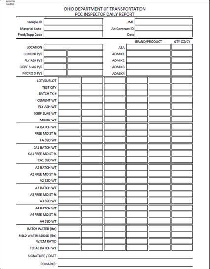
Figure 499.W – Form SiteManager TE-45, Concrete
Inspector's Daily Report
The worksheet above that
matches input information for the SiteManager Test
Screen [PCC INSPECTOR DAILY REPORT TE45 PART 1 –
BATCH WT] is available on the OMM
website at: Site
Manager TE Forms - All Documents
The following are
instructions for filling out the TE-45 form part 499D.
1. SAMPLE ID – The Sample ID number is a
computer-generated number. This number is generated by SiteManager
when data is entered onto the Sample screen. The number is used to refer to the
TE-45 and any cylinder and/or beam specimens made that day.
2. JMF – The JMF space on the form
is for the Job Mix Formula Number assigned to the concrete being produced and
tested. The JMF
is a list of the materials that are in the mix and should be provided by the
Ready Mix producer supplying the concrete.
The JMF can be verified by going to SiteManager icon ![]() , then
, then ![]() , and then,
, and then,
![]() to look up the Concrete JMF’s.
to look up the Concrete JMF’s.
3. MATERIAL CODE - The Material Code section of the TE-45
form is a number assigned to the type of concrete represented by the sample.
These codes are available on the JMF in SiteManager.
4. ALT CONTRACT ID – SiteManager
term for project number.
5. P/S CODE – This is the Producer/Supplier code. In this case, it is the code for the Ready
Mixed Concrete Company. This number can
be found in SiteManager by going to the JMF screen.
6. DATE MADE - This is the date that the concrete is
made.
7. LOCATION - Location of Sample C, also note CLASS OF
CONCRETE - The class of concrete to be used on any given item should be
determined from the plans. Just place
the name of the class in this box.
8. CEMENT P/S – Name on first ticket of each day and
compared to JMF for QC mixes. Actual producer supplier code can be found in
the JMF or SiteManager icon
![]() .
.
a. CEMENT - Look on the approved list on the Materials Management
website under S 1028 - Cement Certified List.
Make sure to use the code for a MFG PLANT and
not a TERMINAL Location. The MFG PLANT location
should be on the Bill of Lading for the cement
9. FLY ASH P/S – Name on first ticket of each day and
compared to JMF for QC mixes. Actual producer supplier code can be found in
the JMF or SiteManager icon
![]() .
.
a. FLY ASH - Look
on the approved list on the Materials Management website under S 1026 - Fly Ash
Certification List.
10. GGBF SLAG P/S – Name on first ticket of each day and
compared to JMF for QC mixes. Actual producer
supplier code can be found in the JMF or SiteManager icon ![]() .
.
a. GGBF SLAG - Acceptable sources of this material can be
found in the ISRC screen of SiteManager.
Use material code 37603 for GRADE 100 material and 37604 for GRADE 120
material.
11. MICRO SI P/S – Name on first ticket of each day and
compared to JMF for QC mixes. Actual producer supplier code can be found in
the JMF or SiteManager icon
![]() .
.
a. MICRO SILICA - Acceptable sources of this material can
be found in the ISRC screen of SiteManager.
Use material code 37601 for POWDER material and 37601S for SLURRY material.
12. AEA – Company and brand name on first ticket of each
day. Approved types can be checked on
the QPL list.
13. ADMIX 1 – Company and brand name on first ticket of
each day. Approved types can be checked on the QPL
list.
14. ADMIX 2 – Company and brand name on first ticket of
each day. Approved types can be checked on the QPL
list.
15. ADMIX 3 – Company and brand name on first ticket of
each day. Approved types can be checked on the QPL
list.
16. ADMIX 4 – Company and brand name on first ticket of
each day. Approved types can be checked on the QPL
list.
17. LOT/SUBLOT – If QC/QA
concrete with sublots – record the number of the sublot and lot you are testing.
18. TEST QUANTITY – The space is to show how many cubic
yards (cubic meters) of concrete the TE-45 test represents. The space shows how
much concrete was produced during the day the report represents.
19. BATCH TK# – The number of the on the batch ticket for
the concrete being tested.
20. CEMENT WT – Batched ticket
cement weight for a cubic yard (cubic meter).
21. FLY ASH WT – Batched ticket
fly ash weight for a cubic yard (cubic meter).
22. GGBF SLAG WT – Batched ticket ggbf slag weight for a cubic yard (cubic meter).
23. MICRO SI WT – Batched ticket
micro silica weight for a cubic yard (cubic meter).
FINE AGGREGATE
24. FA BATCH WT – Reported batch
weight – can be worked per cubic yard.
25. FA FREE MOISTURE % – Percent reported on ticket –
absorption for the aggregate.
Aggregate
absorptions are posted on OMM website on aggregate
information page:
http://www.dot.state.oh.us/Divisions/ConstructionMgt/Materials/Pages/AggregateInformation.aspx
26. FA SSD WT
– Weight with water absorbed. See
Example 2 below.
27. CA1 BATCH WT – Reported
batch weight – can be worked per cubic yard.
28. CA1 FREE MOISTURE % – Percent reported on ticket –
absorption for the aggregate.
Aggregate
absorptions are posted on OMM website on aggregate
information page:
http://www.dot.state.oh.us/Divisions/ConstructionMgt/Materials/Pages/AggregateInformation.aspx
29. CA1 SSD WT
– Weight with water absorbed. See
Example 2 below.
30. FA SSD WT
– Weight with water absorbed. See
Example 2 below.
31. A1 BATCH WT – Reported batch
weight – can be worked per cubic yard.
32. A1 FREE MOISTURE % – Percent reported on ticket –
absorption for the aggregate.
Aggregate
absorptions are posted on OMM website on aggregate
information page:
http://www.dot.state.oh.us/Divisions/ConstructionMgt/Materials/Pages/AggregateInformation.aspx
33. A1 SSD WT
– Weight with water absorbed. See Example
2 below.
34. BATCH WATER (lbs) – Water batch according to Batch
Ticket.
35. FIELD WATER ADDED (lbs) = Water added by truck tank
meter.
36. W/CM RATIO = Total water divided by total cement fly
ash etc.
Example 1:
1. CORRECTED SSD WEIGHT (for
Sp. Gr) - This is the SSD design weight of the
aggregates adjusted for specific gravity.
This is calculated by multiplying the SPECIFIED SSD
WEIGHT by the actual SSD specific gravity and
dividing by the design specific gravity.
|
|
(Equation 499.3) |
Where:
![]() = Design Weight
(SSD) from the appropriate table in 499.03 or 499.04
= Design Weight
(SSD) from the appropriate table in 499.03 or 499.04
DSG =
Design Specific Gravity from Table 499.A
ASG =
Actual SSD Specific Gravity to be used on the project
Adjusted
![]() = Design Weight (SSD)
adjusted for the actual aggregate specific gravity
= Design Weight (SSD)
adjusted for the actual aggregate specific gravity
Example 2: Aggregate
Batch Weight – Determine Free Moisture
1. AGGREGATE QUANTITIES FOR 1 yd3 BATCH WITH CORRECTIONS
FOR MOISTURE -. Each aggregate used
should be adjusted for moisture in the following manner:
a. BATCH WEIGHT - The batch weight is the weight on the
ticket corrected to 1 cubic yard.
(Example = 12,400 lbs for 10 yards = 12,400/10 = 1,240 lbs per cubic
yard.)
b. TMCF = The Total Moisture per Cubic Yard (%). The reported aggregate moisture content for
the batch. IF QUESTIONING THE VALUE FROM
THE READY MIXER, ASK HOW MEASURED OR REQUIRE AN AGGREGATE MOISTURE TEST.
c. AMCF – Absorbed Moisture per Cubic Yard (%). The Department’s established moisture
absorption for the aggregate source.
i.
Aggregate
absorptions are posted on OMM website on aggregate
information page:
http://www.dot.state.oh.us/Divisions/ConstructionMgt/Materials/Pages/AggregateInformation.aspx
FMCF = ![]()
The formula involves changing
the two percent’s to a decimal form by moving the decimal two places to the
left and adding 1.
FMCF = ![]() 1.0467/1.0074 = 1.039
1.0467/1.0074 = 1.039
|
BATCH WEIGHT A |
SSD weight (B) |
free water a-b |
|
1382 |
1382 x
1/1.039 = 1330 |
1382-1330 = 52 |
Example 3:
1. W / CM RATIO – Determine the required
Water/Cementitious Ratio (W/Cm) from the contract documents or JMF.
2. TOTAL CM WEIGHT – Sum the weights of all of the
cementitious materials.
3. TOTAL WATER – Sum the BATCH WATER + the FIELD ADDED
WATER + aggregate BATCH WEIGHTS – aggregate SSD
WEIGHTS. Equals TOTAL WATER.
4. WATER IN ADDITIVES - Water in additives needs to be
accounted for in the mix water. This is
generally used when the micro silica used is in slurry form. You would then determine the amount of solid,
determine how much is used, and how much of the slurry was water.
Example: A
slurry mix is used in a Class QC 3 mix.
There is to be 30 lbs of micro silica in each yd3 of concrete. Determine
how much slurry is needed per yd3 and how much water is contributed to the mix
if the slurry contains 42 percent micro silica solids.
30 lbs micro ÷ 0.42 = 71.4 lbs of slurry
required
71.4 lbs slurry - 30 lbs micro = 41.4 lbs
of water added to the mix
BATCH WATER + FIELD WATER ADDED + (FA BATCH WT – FA SSD WT)
+ (CA BATCH WT – CA SSD WT) + (A1 BATCH WT – A1 SSD WT)
200 lbs + 15 lbs + (1382 – 1330) + (1240 – 1260) +
(350 – 335) = 200 + 15 + 52 – 20 + 15 = 262 lbs
TOTAL CM WEIGHT = CEMENT WT
+ FLY ASH WT + GGBF SLAG WT + MICRO WT. = 350 + 100 + 150 + 20 = 620 lbs
W/CM RATIO =
262/620 = .43
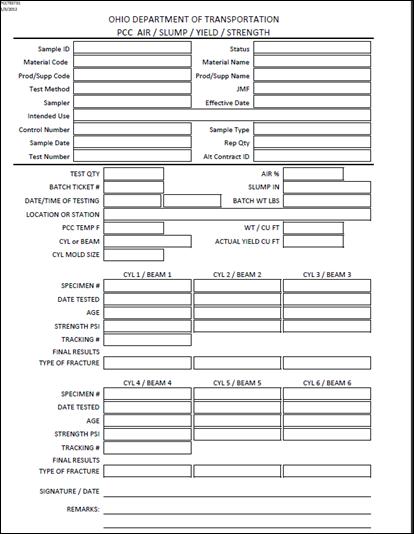
Figure 499.X – Form SiteManager TE-45, Concrete Inspector's Daily Report
The worksheet above that
matches input information for the SiteManager test
screen [PCC INSPECTOR DAILY REPORT TE45 PART 2 –
TESTS] is available on the OMM website at: Site
Manager TE Forms - All Documents
The following are
instructions for filling out the TE-45 form part 499E.
1. SAMPLE ID – The Sample ID number is a
computer-generated number. This number is generated by SiteManager
when data is being entered onto the Sample screen. The number is used to refer
to the TE-45 and any cylinder and/or beam specimens made that day.
2. MATERIAL CODE – The Material Code section of the TE-45
form is a number assigned to the type of concrete represented by the sample.
These codes are available on the JMF in SiteManager.
3. MATERIAL NAME – Note CLASS OF CONCRETE – The class of
concrete to be used on any given item should be determined from the plans. Just place the name of the class in this box.
4. P/S CODE – This is the Producer/Supplier code. In this case, it is the code for the Ready
Mixed Concrete Company. This number can
be found in SiteManager by going to the JMF screen.
5. P/S NAME – In this case, it is the name for the Ready
Mixed Concrete Company. This name can be
found in SiteManager by going to the JMF screen.
6. TEST METHOD – number of the SiteManager
test screen.
7. JMF – The JMF space on the form
is for the Job Mix Formula Number assigned to the concrete being produced and
tested. The JMF
is a listing of the materials that are in the mix and should be provided by the
Ready Mix producer supplying the concrete.
The JMF can be verified by going to SiteManager icon![]() , then
, then ![]() , and then
, and then ![]() to look up the Concrete JMF’s.
to look up the Concrete JMF’s.
8. SAMPLER – Your name.
9. EFFECTIVE DATE
10. INTENDED USE – What the concrete is being used for –
deck pier column, etc.
11. CONTROL NUMBER
12. SAMPLE TYPE – Typically this will be a Control Sample
(JCTL), Independent Assurance Sample (IAS), or Information (INF) sample. Other options for type of sample can be found
in SiteManager.
13. SAMPLE MADE - This is the date that the concrete is
made.
14. ALT CONTRACT ID – SiteManager
term for project number.
15. TEST QUANTITY – The space is to show how many cubic
yards (cubic meters) of concrete the TE-45 test represents. The space shows how
much concrete was produced during the day the report represents.
16. AIR % – Test value from running air content test
17. BATCH TK# – The number of the on the batch ticket for
the concrete being tested.
18. SLUMP IN – Slump test results in inches.
19. DATE/TIME OF TESTING
20. BATCH WT LBS
21. LOCATION OR STATION
22. PCC TEMP F = Tested temperature of the concrete.
23. WT/CU FT = Tested weight of the concrete.
24. CYL or BEAM – Type of strength test sample made.
25. ACTUAL yield in CUBIC FT – Tested yield.
26. CYL MODL SIZE – 4 inch x 8
inch? 6 inch x 12 inch?
27. SPECIMEN # – Number assigned to the strength samples –
cylinders or beams (example 1A, 1B, and 1C for three 4-inch x 8-inch cylinders
specimen’s).
28. DATE TESTED – Date the laboratory tests the specimens.
29. AGE – Number of days from the date sampled to the date
tested.
30. STRENGTH PSI
31. TRACKING # - Internal laboratory number.
32. TYPE OF FRACTURE – Description of how the sample
broke.
Check
List for Inspection
Concrete Plants –
Either Ready Mix or Plant on Site
Producer/suppliers of
concrete are responsible for delivery of concrete and quality control. Items below are their responsibility but you
or your District Concrete Monitor should randomly ensure these items
comply. When concrete delivery is not
good, these items become more critical.
When making these checks,
ensure the supplier is with you, and obtain documentation from the supplier as
to what corrections they will be making to conform to requirements.
1. Check foundations of stockpiles for proper preparation
and adequate drainage.
2. Observe stockpiling of aggregate to ensure that
handling does not cause segregation, contamination, or intermingling.
3. Observe charging of plant bins to ensure that
materials are not being intermingled.
4. Check bins for adequate partitions to prevent
intermingling of aggregate.
5. Check scales with test weights throughout range of use
and determine percent of error. If error
is greater than ± 0.5 percent, scales must be adjusted and rechecked. Record checks made and issues. Do not accept concrete until corrected.
6. Determine how the supplier will determine moisture
content of their aggregates. Calibrated
probes are acceptable as are moisture tests.
Agree on the frequency of moisture and probe calibration. Work with your district concrete monitor on
these issues. Depending on the job size,
randomly verify moistures of aggregates.
7. Check scales for seal by the Sealer of Weights and
Measures or of a scale servicing company.
Record. If not sealed, do not
accept concrete.
8. Check scales for "zeroing." Have adjustments made when needed.
9. Check water meter, both plant and truck, for accuracy.
Record information. Do not accept concrete
from equipment not meeting 499.
10. Randomly ensure that truck wash water is removed from
the truck.
11. Check admixture dispensers for accuracy.
12. Check mixers to ensure that hardened concrete is not
built up around blades.
13. Inspect hauling units for cleanliness, condition of
blades, and operation of counters.
14. Check to ensure that all materials have been sampled,
tested, and approved or certified prior to start of concrete production.
15. Ensure quantities obtained from the Job Mix Formula (JMF) are adjusted for changes in specific gravity,
moisture, and absorption. Discuss with
the supplier how they are doing this before delivery of concrete.
16. Ensure aggregate quantity adjustments are within the
acceptable range of 499 based on the JMF quantities.
17. Observe batching operations at start of production and
periodically when required.
18. During mixing or delivery from the truck, do not
accept balling of materials. Do not
accept attempts to remove balls by hand.
Reject the mixing operations or trucks.
19. If water is added at project site, ensure 30
additional mixing revolutions are required
20. Ensure you receive both batch tickets. If the first ticket of the day is not
provided, immediately notify the supplier.
21. Do not accept handwritten batch tickets.
22. Assure retarder is added when temperatures require and
assure the dosage meets the manufacturer’s requirements.
23. Notify supplier to make adjustments as needed to
maintain air, slump, and yield within tolerance. When slump adjustments are done with superplastizer on the jobsite, ensure a Type F or G is used
and dosages are within manufacturer’s recommendations.
24. Ensure W/C ratios are not exceeded at any time. Immediately require corrections and report
the quantity of material with high W/C ratios and non-specification material.
25. Ensure trucks discharge all concrete within the
required time from batching to discharge. (499)
26. When adjustments are made in the mix design, check to
ensure that proper batch weights are shown on tickets.
27. Periodically check transit and central mixers to ensure
compliance with manufacturer's recommended mixing speeds.
28. Complete SiteManager TE-45
Report or test screens and submit to the District laboratory.
Conversion Factors:
|
|
MULTIPLY |
BY |
TO GET |
|
Area |
1 square foot 1 square inch |
0.0929034* 645.16* |
square meter (m²) square millimeter (mm²) |
|
Length |
1 inch 1 foot 1 mile |
25.4* 0.3048* 1.609344 |
millimeter(mm) meter (m) kilometer (km) |
|
Mass |
1 pound |
0.453592 4 |
kilogram (kg) |
|
Mass per volume |
1 pound/cubic foot 1 pound/cubic yard 1 pound/gallon |
16.018846 0.5932764 0.1198264 |
kilogram/cubicmeter (kg/m³) kilogram/cubic meter (kg/m³) kilogram/liter (kg/L) |
|
Pressure (stress) |
1 pound/square inch 1 pound/square foot |
0.0068944 47.88026 |
megapascals
(Mpa) pascal
(Pa) |
|
Temp |
Fahrenheit (oF) |
(oF-32)/1.8) |
Celsius (oC) |
|
Volume |
1 fluid ounce 1 cubic yard 1 cubic foot 1 cubic foot 1 gallon |
29.57353 0.7645549 0.02831685 28.31685 3.785412 |
milliliter (mL) cubic meter (m³) cubic meter (m³) liter (L) liter (L) |
|
Volume per mass |
1 fluid ounce / cubic
yard 1 fluid ounce / 100
pounds 1 gallon / cubic yard |
38.68071 65.19847 4.951132 |
milliliter/cubic meter (mL/m³) milliliter/100 kilogram (mL/100 kg) liter/cubic meter (L/m³) |
*exact conversion
Documentation
Requirements - 499 Concrete
1. Fill out the SiteManager TE-45
and report results in SiteManager.
a. Ensure that specified w/cm ratio is not exceeded.
b. Record temperature of mix.
c. Record mix design adjustments on form TE-45.
d. Make sure that correct aggregates being used match the
JMF.
e. When reporting Contractor reported test results, only
complete test screen
i.
PCC INSPECTOR DAILY REPORT TE45 PART 2 – TESTS.
f. When reporting tests, ODOT has performed complete test
screens.
i.
PCC INSPECTOR DAILY REPORT TE45 PART 1 – BATCH WT.
ii.
PCC INSPECTOR DAILY REPORT TE45 PART 2 – TESTS.
2. If water is added at project site, document and check
the w/cm is not exceeded.
3. Document that pavement aggregates meet 703.13.
4. Document random aggregate moisture checks.
5. Ensure that batch tickets are provided as specified in
499.07.
a. Randomly check batching quantities on ticket against JMF.
i.
When performing
verification testing, check the time loaded and the time discharged are within
requirements.
Mixers
and Agitators
Mixers and Agitators shall
meet the requirements of AASHTO M 157, Sections 10, 11.2, 11.5, 11.6 (ASTM C94, Sections 11, 12.2,
12.5, 12.6)