630 Traffic Signs and Sign Lighting
630-1 Traffic Signs and Sign Lighting - General
630-4 Overhead Supports in General
630-5 Overhead Sign Supports By Type
630-6 Ground-Mounted Sign Supports
630-1 Traffic Signs and Sign Lighting - General
This information is
intended to serve as a guide for construction personnel where the contractor
furnishes and installs traffic control devices and appurtenances. However, it
may also be useful for maintenance personnel performing the same functions.
Inspection procedures for various types of traffic control devices are
outlined, mainly in the form of check lists to assist project personnel in
performing their duties. This information points out the various important
features of each device and references the applicable specification or standard
drawing. Illustrations are used for easy recognition of the device or feature
being discussed.
630-2 Sign Service
Sign service shall
comply with SCDs TC-32.10
and TC-32.11
and the plans. Additional information is provided in TEM Section 240-7.2 and
CMS Item
631.04. Basically, it consists of cable and equipment to provide a complete
electrical service from either an underground source or an overhead direct drop
to separately furnished disconnect switch with enclosure. The equipment could
include weather head, a conduit riser with necessary fittings, attachment
clamps and cable. A thorough review of
the plans should be made to determine the specific requirements of the
maintaining agency for sign service.
When required, an
electric meter base will be furnished by the applicable utility and installed
by the contractor as part of the sign service work.
The sign service is
to terminate at the meter base, if used; otherwise termination will be at the
switch enclosure. Sign service could be by:
- Direct drop by means of a weatherhead
and conduit riser routed to the switch enclosure;
- Underground conduit and the pole
interior to the enclosure; or
- Underground and structure-attached
conduit to the enclosure (for overpass mounted signs).
The conduit riser is
to comply with CMS Item 713.04,
725 and the
plans, and the weatherhead is to be threaded aluminum or galvanized ferrous
metal (CMS Item
732.16).
The disconnect
switch is to be a single-throw safety switch meeting the voltage and capacity
requirements of the plans. The enclosure is to be a NEMA Type 4 ICS 1-110.15
with sufficient volume to accommodate an internal transformer when specified.
The enclosure is to contain a solid neutral bar.
A ground wire is to
be used as shown on SCDs TC-32.10
and TC-32.11
leading to a ground rod installed in accordance with TEM Section 240-7.3.
630-3 Foundations
630-3.1 Staking
Sign support
foundations are to be located so that the sign face is at a right angle to the
roadway lanes served, unless the plans specify otherwise. An example of an
exception is the W-32 Large Arrow sign (black arrow on yellow background) which
is located as shown in TEM Figure 298-24.
Foundations should
be staked by the contractor in accordance with the locations shown on the
plans.
The stakeout
locations should be checked for:
- The presence of obstructions which could
restrict motorists' proper visibility of the sign from the point where
they are expected to read the sign. Curved roadway locations should
especially be checked.
- Obvious conflicts with overhead power lines or other utilities. There should be available a proper safe clearance from overhead lines for construction operations, in compliance with the National Electric Safety Code and any local codes.
- Possible conflict with underground
facilities.
Foundation locations
may be adjusted when necessary to overcome difficulties such as those shown in TEM
Figure 298-24 and discussed herein, with the concurrence of the project
engineer. Adjustment should not violate minimum clearance dimensions as shown
on SCDs TC-42.10
and TC-42.20
and the OMUTCD.
630-3.2 Excavation
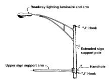
Foundations shall be placed only in undisturbed soil or compacted embankment and excavation shall be by an earth auger of the specified diameter to the specified depth. See TEM Figure 298-25 for a diagram of a foundation excavation.
If a minor cave-in should occur, the contractor may continue excavation using an increased diameter; or use sleeving, casing or other method approved by the project engineer. However, the foundation concrete will be measured as determined from plan dimensions. The contractor must remove all extraneous material from the excavation before concrete placement. When subsurface obstructions are encountered, permission may be granted by the project engineer to replace the excavated material and relocate the foundation. When bedrock is encountered, that portion of the specified foundation depth within the bedrock may be reduced as much as 50 percent.
630-3.3 Placement
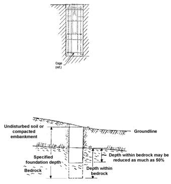
Anchor bolts and conduit ells are to be of the correct size and furnished with the support. At least one 2 inch (51 millimeters) minimum conduit ell is to be furnished and capped if unused. Anchor bolts, conduit ell(s) and EMT (Electric Metallic Tubing) are to be oriented in the foundation according to the plans, conduit runs and ground rod location. All anchor bolts are to be provided with standard steel hex nuts, leveling nuts, plain and lock washers. The nuts are to be capable of developing the full strength of the anchor bolts. Reinforcing bars, tie loops and tie bars are to be of the correct size and arranged with the anchor bolts into cages according to the applicable SCD TC-21.10 or TC-21.20. A special foundation design will be required when soil with a load bearing capacity of less than 2,000 pounds per square foot (9700 kg/m2) is encountered.
Anchor bolts are to be vertical with their ends projecting the correct distance above the foundation surface in compliance with the plans. When the distance the anchor bolts project above the foundation surface is not specified, a rule of thumb is four times the bolt diameter. The anchor bolts are to be tied to the cage tie bars according to standard details.
The cage is to be supported 3 to 4 inches (75 to 100 millimeters) above the bottom of the excavation by a piece of concrete block or similar material. The cage is to be positioned with a clearance of 3 inches (75 millimeters) from the excavation wall by similar blocking so that after concrete placement a full thickness cover is assured. A template and/or frame is to be used to rigidly hold the anchor bolts and conduit ell(s) in the specified pattern during concrete placement. A form is to be oriented according to the plans to shape the foundation into a square from the surface or grade shown to a nominal 6 inches (150 millimeters) below ground line. The template and form may be combined. Gaps of 6 inches (150 millimeters) or less between the foundation and adjacent paved surfaces are to be eliminated by increasing the formed foundation.
Water encountered in the foundation excavation is to be pumped out before concrete placement.
If this is not feasible, concrete should be placed by the tremi-tube method.
Concrete conforming to CMS Item 499 and CMS Item 511 is to be placed and vibrated to eliminate voids. Care should be exercised during vibrating to avoid disturbing the anchor bolts, conduit ell(s) and reinforcing cage.
Forms may be removed as soon as the concrete has hardened sufficiently so as not to be susceptible to damage (CMS Item 511.13).
Minor earth caving external to the hole which may have occurred during excavation using sleeving or casing should be corrected after concrete placement by backfilling and tamping in accordance with CMS Item 203.
Joint filler complying with CMS Item 705.03 is to be placed between the formed foundation and adjacent paved surfaces.
Supports and poles may be erected, signs installed and span wire load applied only after the concrete has aged sufficiently to be in compliance with Section 630-3.4.
630-3.4 Curing and Loading
Curing and loading of concrete for traffic control devices is to comply with CMS Item 511.14.
Concrete for foundations of sign supports is to be cured, have bracing removed and be loaded only when the concrete has achieved the age shown below:
|
|
Age of Concrete in Days |
|
|
|
Without Beam Test |
With Beam Test ** |
|
Curing |
7 |
5 |
|
Removing Bracing |
7 |
3 |
|
Loading* |
14 |
7 |
* No load is to be applied or other work done that will damage new concrete or interfere with its curing.
** Beam test specimens are to be poured from the same batch, immediately before, during or after foundation pour. Specimen configuration is to be to ODOT requirements. Specimens when tested must have at least an average modulus of rupture for two tests of not less than 650 pounds per square inch (4.5 MPa).
630-4 Overhead Supports in General
630-4.1 General
Various general aspects of overhead sign supports are addressed in this section. TEM Table 297-7 provides an overall summary of the structure types, allowable sign area on each and the span or arm length.
630-4.2 Pole and Support Inspection
This inspection checklist covers the general features of strain poles, mast arm type signal supports and overhead sign supports. Features pertaining only to specific pole or support types will be found in the sections of this manual covering exclusively those poles or supports.
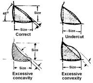
- When poles and supports of the combination type are specified, they are to provide extra length as necessary for a highway lighting function and welded-on bracket arm plate(s) complying with SCD HL- 10.12 or HL-10.11, for attachment of a separately furnished luminaire arm. An upper handhole and an additional internal J-hook are to be furnished.
- Supports may be of an alternate design utilizing all non-tapered tubing structural members.
- Poles and supports should be inspected when received if possible, but certainly prior to erection.
- General dimensions should be checked first, including pole length, base diameter, top diameter, and wall thickness. Similar mast arm dimensions should also be checked. Wall thickness is most easily measured with calipers at the end. Caps on poles may have to be removed.
- Orientations of the various appurtenances should be checked against the plan’s orientation diagram if such is available; otherwise orientations may be determined from certified shop drawings and the intersection drawing.
- Base plate dimensions should be checked including thickness, bolt circle diameter and bolt hole size. Base plates may be plate or cast steel according to CMS Item 730.04.
- A handhole with ground lug is to be furnished, with a cover plate complying with CMS Item 730.05 and a stainless steel chain complying with CMS Item 730.10.
- Blind half-couplings are to be provided where required. Sharp edges are to be rounded to prevent damage to cable or wires. Blind half-couplings are to be plugged when not in use. Couplings may be for signal or interconnect cable entrance or for attaching supports for traffic control equipment and for hubs for controller cabinets. Entrance couplings are to be threaded for use with threaded weatherheads.
- An internal J-hook is to be furnished and located as indicated on the plans.
- A pole cap conforming with CMS Item 730.06 is to be furnished, and must be in place before final inspection.
- An arm cap conforming with CMS Item 730.07 is to be furnished for chords or mast arms.
- All strain poles and overhead sign and signal supports are to be grounded (even if no power is available).
- Welding is to be inspected in accordance with TEM Section 630-4.3.
- Galvanizing is to be inspected in accordance with TEM Section 630-4.4.
- When required by the plans, supports are to include sign brackets, U-bolts, clamps, luminaire support arms, bracing rods, other necessary structural members and signal hanger clamps with clevis.
- The correct number and size of anchor bolts and conduit ells are to be furnished for placement in the foundation.
- Anchor bolt diameter and length are to be according to the plans and SCD TC-21.10 or TC- 21.20. Anchor bolt ends may have an L-bend or be fitted with a tapped steel plate. Threaded ends are not to be damaged and are to be galvanized at least 2 inches (50 millimeters) beyond the threads. The galvanizing should be in good condition, and absent or damaged galvanizing should be repaired by the application of two coats of zinc-rich paint. Galvanizing thickness should permit the turning of nuts by a wrench without difficulty. Loose rust on anchor bolts should be removed.
- All anchor bolts are to be provided with standard steel hex nuts, leveling nuts, plain washers and lock washers. The nuts are to be able to develop the full strength of the anchor bolts.
630-4.3 Inspection of Welds
All welds of supports shall be inspected visually as soon as possible following support delivery. Welds should be inspected for flaws and imperfections under good lighting conditions using a magnifying glass as necessary. Evidence of any of the following faults or other imperfections such as warping and misalignment may be cause for rejection of the support. The following features of welds should be checked:
- A check should be made for the actual presence of all welds called for by the certified shop drawings and standard drawings.
- Welds on tapered tubes, pipe or structural shapes are to be continuous around the joint. Welds requiring terminations are to be of the correct length.
- Welds are not to exhibit cracks or discontinuities in base metal or weld material and are not to show evidence of porosity, showing up as pitting or pinholes. The galvanizing layer may cover such flaws, but their existence should be checked.
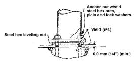
- Welds are to be full cross section without excessive concavity or convexity. Required weld terminations are to be filled to full section without depressions or craters.
- There should be no evidence of undercut, a condition where a shallow groove is melted into the base metal adjacent to a weld and left unfilled by weld metal.
- Base plates are to be welded to two ply poles with AWS prequalified welds in conformance with CMS Item 730.04.
- Arm attachment plates are to be welded inside and outside with fillet welds. Each fillet weld is to be equal to the wall thickness of the respective tubing.
630-4.4 Inspection of Galvanizing
The galvanizing cover of supports is to be inspected visually as soon as possible following delivery. The galvanizing should be inspected externally and internally for flaws and imperfections in daylight or strong artificial light. In accordance with CMS Item 513.22, supports are to be loaded, transported, unloaded, stored and erected in a manner avoiding damage to any feature including the galvanizing. Supports stored in the field should be kept off the ground to prevent the galvanizing from contacting water which may result in a premature oxidation condition. The galvanizing should have the appearance of a uniform application. Supports should be checked for assurance that the following flaws or imperfections do not exist:
- Loose or bare spots in the galvanizing where improper preparation has prevented metal adherence in the molten zinc bath. Poles should be rejected if the point of a penknife can flake off the galvanizing layer.
- General overall roughness, a symptom of overpickling or of excess zinc bath temperature and/or immersion time.
- Pimples, due to entrapped bath scum particles.
- Blisters, due to hydrogen gas absorbed during pickling and coming out at the time of galvanizing.
- Flux inclusions, picked up from the top of the bath when dipping and burnt-on during immersion.
- Ash, usually in course lumps picked up from the top of the bath.
- Patches of dull gray coating, due to the slow cooling of heavier cross sections of supports after immersion.
- Excess zinc lumps or runs, due to delayed molten metal run-off from surface discontinuities such as joints, seams or holes.
- Rust stains, due to the weeping of impurities from the pickling process at seams and folds. Excessive galvanizing faults and imperfections combined with general poor workmanship may be cause for rejection of the support. Gross imperfections may lead to the suspicion of inadequate protective cover which may require inspection with a magnetic instrument. Items 1 through 6 may be cause for rejection. Items 7 through 9, if extreme, may also be cause for rejection, because of poor appearance even if the protection of the support is not affected.
After erection, supports should be given a final inspection for any damage to the galvanizing due to improper handling in the erection process. Damage due to slings, etc., which is more serious than superficial brightening is to be repaired by the contractor with the application of two coats of zinc-rich paint.
630-4.5 Weight of Supports
TEM Tables 297-8a through 297-8f provide information on the weight of various overhead sign supports. For all structures, the weight of the pipe support has been given where pipe has been frequently used in place of tapered tubes. In general, the tapered tube support will be lighter than the pipe support. The support numbers listed may be preceded by I-129, 815, 844 or other designation instead of TC.
For estimating purposes, a 10 x 10 foot (3.0 x 3.0 meter) sign (including the sign lighting) weighs approximately 400 pounds (181 kilograms).
630-4.6 Assembly and Erection Procedure
Erection procedures pertaining to specific pole or support types will be found in the sections of this manual devoted exclusively to those poles or supports. In general the following assembly and erection procedure applies:
- To minimize erection time and the hazard to workers and motorists where traffic is maintained, supports should be erected with mast arms attached, and horizontal sign support members (over the roadway) should be prewired for lighted signs or other traffic control devices. See the notes in plans for traffic maintenance requirements when span-type sign support members are erected.
- Support components are to be assembled with their threaded fasteners tightened in accordance with CMS Item 630.06. Fasteners ½ inch (13 millimeters) or greater shall have anaerobic adhesive applied to the threads according to the manufacturer’s recommendations. Nuts may be tightened by the “turn of the nut” method or by means of a torque wrench.
- The “turn of the nut” method shall be in accordance with CMS Item 513.15. Nuts shall be made snug tight by the effort of a person using an ordinary spud wrench followed by an additional 1/12 to 1/3 turn.
- Tightening by a torque wrench is to obtain a bolt tension between 80 percent and 100 percent of the proof load for the bolt size as listed in the Society of Automotive Engineers Handbook and shown in TEM Table 297-10.
- Leveling nuts shall be placed on the anchor bolts, initially clearing the foundation surface by at least 1/4 inch (6 millimeters) and forming a horizontal plane.
- Poles or supports shall be raised into position with equipment of adequate lifting capacity and used in a manner preventing damage to attached appurtenances (signs, brackets, luminaires, etc.) or to the galvanizing. The weight of poles or supports is given in TEM Section 630-4.5 for the use of the contractor in the erection procedure.
- With the pole or support’s baseplate resting on the leveling nuts, the lock washers and anchor nuts are to be placed on the anchor bolts, the support plumbed in a vertical position or raked as required, and anchor nuts given a preliminary tightening.
- After any necessary leveling nut adjustments are made to assure that supports are essentially vertical after attachment of signs, sign lighting equipment or signals the anchor nuts are to have anaerobic adhesive applied and be final tightened in accordance with the instructions for assembling fasteners given in the foregoing paragraphs 2, 3 and 4.
- Anchor nuts are to be covered with bolt covers or a cover base when poles are erected in sidewalks, traffic islands, curbed areas and seeded areas of urban character (CMS Item 630.06 B and 632.15).
- Poles or supports which are prewired before erection should be checked to determine if the erection procedure has disturbed the wiring. Wire for lighted signs should be supported by looping wire over the J-hook in the vertical support member (CMS Item 631.05). Cable supported by cable support assemblies should be checked to determine if the sling is over the J-hook and adjustment is proper to eliminate strain on the cable jacket.
630-5 Overhead Sign Supports By Type
630-5.1 General
Section 630-4.6 addressed general assembly and erection guidelines for strain poles and supports. The following sections provide additional information specific to various types of supports. For the most part the information is provided in a checklist format.
630-5.2 Span Wire Support
Span Wire sign supports shall comply with SCD TC-17.10 and the plans. These sign supports consist of strain poles, messenger wire with accessories and sign hangers. Strain pole size and type, anchor base or embedded, shall be as specified.
- Strain
poles are to be inspected in accordance with Section 632-6.1 and general features of the
poles inspected in accordance with Section 630-4.2. Welds are to be
inspected according to Section 630-4.3 and the galvanizing
inspected according to Section 630-4.4.
- Erection is to be in accordance with the general procedure given in Section 630-4.6 except as hereafter noted.
- For the initial rake of strain poles of the anchor base type or embedded type poles, see Section 632-6.1.
- The upper messenger wire is to be assembled with its accessories according to the standard drawing. Preformed guy grips are not permitted because wind loads on the signs can cause failure of the grips. Alternate methods of attaching messenger wire to strain poles may be used:
i. Span wire clamp with clevis, anchor shackle and thimbles on the messenger wire, or
ii. Messenger wire wrapped twice around the strain pole and secured with a 3-bolt clamp of the proper size.
- The upper messenger wire is to be fitted with its signs, furnished under other items of work, and the vertical clearance to sign bottoms adjusted within clearance limits over the roadway. The sag of the upper messenger wire is to be between 4 and 5 percent.
- It is essential that the lower messenger wire have more slack than the upper wire. The sag should be approximately 3 inches (75 millimeters) greater than the upper wire. This sag adjustment is to be made before the sign hangers are attached to the lower wire.
- Sign hangers are to be clamped snugly to the lower wire by U or J bolts. In the case of back-to-back signs, the lower messenger wire running in between the sign hangers, is clamped between bolted spacers that are slightly thinner than the messenger wire (see SCD TC-17.10).
630-5.3 Single Arm Support
- Single arm supports shall comply with certified shop drawings, SCD TC-16.20 and the plans.
- General features of the support shall be inspected in accordance with Section 630-4.2.
- Welds shall be inspected according to Section 630-4.3 and the galvanizing inspected according to Section 630-4.4.
- For arms of two telescoping pieces, a 15-inch (400 millimeters) overlap is required. The overlapped arms are to be secured with a stainless or galvanized steel hex head through-bolt with nut.
- Arm caps are to cover at least 50 percent of the end area (CMS Item 730.07).
- A minimum of two brackets are to be provided for each sign, each attached to the arm by steel clamps with carriage bolts. The clamps should be able to be tightened in a manner to firmly grasp the arm so as to prevent sign rotation.
- Only extrusheet type signs are normally lighted. If such signs are lighted, disconnect switch enclosure mounting brackets may be required on the support.
- Erection is to be in accordance with the general procedure given in Section 630-4.5, except as hereafter noted.
- The contractor may choose to attach the signs and any sign lighting items before erection.
- Signs are installed at the same elevation. For this purpose, adjustment is provided by two pairs of slotted holes in the sign bracket for attachment of the arm clamp.
- Contact between galvanized clamp flanges and aluminum sign brackets is to be prevented by the use of chloroprene gaskets.
- Initial rake is to be adjusted so that under the load of signs, the pole will assume an essentially vertical position and the arm rise be within the limits specified on the standard drawing, 3 inches (75 millimeters) minimum, 12 inches (300 millimeters) maximum.
630-5.4 Cantilever Support
- Cantilever supports are to comply with
certified shop drawings, SCD TC-12.30
and the plans.
- General features of the support are to
be inspected in accordance with Section 630-4.2. Welds are to be
inspected according to Section 630-4.3 and the galvanizing
inspected according to Section 630-4.4.
- Supports with arm lengths18 feet (5.5
meters) and over are to have truss members. Truss members may be angles or
pipe.
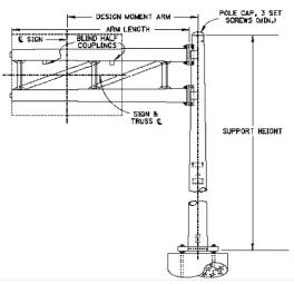
- One blind half coupling is to be welded to
the top chord approximately 12 inches (300 millimeters) beyond or outside
of the first sign bracket for a sign less than 20 feet (6.1 meters) long.
A second blind half coupling is to be welded near the second sign bracket
for signs 20 feet (6.1 meters) or longer.
- Erection is to be in accordance with the
general procedure given in Section 630-4.5, except as hereafter
noted.
- The contractor may choose to attach the
sign(s) and any sign lighting items before erection.
- Signs are centered vertically on the
chords.
630-5.5 Center-Mount Support
- Center-mount supports are to comply with
certified shop drawings, SCD TC-9.30
and the plans.
- General features of the support are to
be inspected in accordance with Section 630-4.2. Welds are to be
inspected according to Section 630-4.3 and the galvanizing
inspected according to Section 630-4.4.
- Sign clearance above the roadway is to
be a minimum of 17 feet (5.2 meters).
- Arms may be either square or round tube.
The arm attachment design is according to standard details for either
square arms or round arms with separate cradle.
- A blind half coupling is located on the
pole.
- Erection is to be in accordance with the
general procedure given in Section 630-4.6, except as hereafter
noted.
- Signs are centered vertically on the
arms.
- Signs may be mounted laterally on the
support in an eccentric position. However, a minimum of 2 feet (0.6
meter) of sign length is to remain to one side of the pole centerline.
- The contractor may choose to attach the
sign and any sign lighting items before erection.
630-5.6 Semi-Overhead Support
- Semi-overhead supports are to comply
with certified shop drawings, SCD TC-9.10
and the plans.
- General features of the support are to
be inspected in accordance with Section 630-4.2. Welds are to be
inspected according to Section 630-4.3 and the galvanizing
inspected according to Section 630-4.4.
- Sign clearance above the ground is to be
at least 10 feet (3.0 meters) unless a lower height is approved by the
project engineer to provide sign visibility through preceding overpass
structure(s).
- Arms may be either square or round tube.
The arm attachment design is according to standard details for either
square arms or round arms with separate cradle.
- A blind half coupling is located on the
pole.
- Erection is to be in accordance with the
general procedure given in Section 630-4.6, except as hereafter
noted.
- Signs are centered vertically on the
arms.
- Signs may be mounted laterally on the
support in an eccentric position. However, a minimum of 2 feet (0.6
meter) of sign length is to remain to one side of the pole centerline.
- The edge of the sign is to be back at
least 2 feet (0.6 meter) from the edge of the curb.
- The contractor may chose to attach the
sign and any sign lighting items before erection.
630-5.7 Span Truss Support
- End frames for span truss supports are
to comply with certified shop drawings, the plans and SCD TC-7.65
for aluminum trusses and SCD TC-15.115
for steel trusses.
- General features of end frames are to be
inspected in accordance with Section 630-4.2. Welds are to be
inspected according to Section 630-4.3 and the galvanizing inspected
according to Section 630-4.4.
- Handholes are to be oriented on the end
frame downstream vertical member on the side away from the direction of
traffic.
- The size of truss members is to be in
accordance with standard details. Truss member joints may be of two
different designs.
- Switch enclosure mounting brackets are
to be in place and a chase nipple installed on both end frame vertical
members which are away from the direction of traffic.
- An angle is to be furnished and welded
onto the end frame, near the top, to support the lower chords of the span
box. Stainless steel U-bolts are to be used with aluminum trusses and
galvanized steel U-bolts used with steel trusses.
- End frame vertical members are to be
furnished with steel clamps and a separate tee or angle (alternate) for
supporting the upper chords of the span box. Stainless steel U-bolts are
to be used with aluminum trusses and galvanized steel U-bolts used with
steel trusses.
- An internal J-hook is to be in each end
frame in the downstream vertical member.
- When using an aluminum truss, the
following shall apply:
- Aluminum trusses are to comply with
certified shop drawings, SCD TC-7.65
and the plans.
- Welds are to be inspected according to Section
630-4.3.
- End caps are to be on each end of
chords. The top front end caps are to be tapped for wiring.
- A blind half coupling is to be welded
to the front top chord of the truss approximately 12 inches (300
millimeters) beyond or outside of the first sign bracket for each sign.
Sharp edges are to be rounded to prevent damage to wires.
- Span length is to be according to shop
drawings and the plans.
- Span box camber is to be in accordance
with standard details.
- Flanges between span box sections may
be cast or fabricated with forged flanges as an alternate.
- Flange attachment hardware is to be
stainless steel bolts and nuts.
- Supports are to be furnished with
necessary sign brackets, U-bolts, luminaire support arms, bracing rods
and other necessary structural members
- When using a steel truss, the following
shall apply:
- Steel trusses are to comply with
certified shop drawings, SCD TC-15.115
and the plans.
- Steel trusses' checking instructions
are the same as those for aluminum trusses, except as hereafter listed.
i.
The
galvanizing is to be inspected according to Section 630-4.4.
ii.
Flanges between
span box sections are to be forged.
iii.
Flange
attachment hardware is to be galvanized steel bolts and nuts.
- See the notes in the plan for traffic
maintenance requirements when span type sign support members are erected.
- The base plates of end frames are to be
placed on anchor bolt leveling nuts, lock washers and anchor nuts placed,
the frames plumbed into a vertical position in both longitudinal and
lateral directions, and nuts made tight in accordance with Section
630-4.6.
- Truss camber is to be correct. The
various truss sections are to be assembled in the arrangement and sequence
shown on the shop drawing.
- Trusses may be assembled into a total
span while lying on blocks with wedges. Flanges on truss section ends may
be aligned by driving in the wedges as necessary. All flange bolts are then
assembled and made tight.
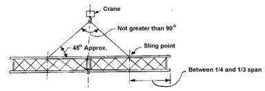
- Two cranes may be necessary when lifting
very long trusses or the heavier steel trusses. For reference, truss
weights are given in Section 630-4.5.
- Care should be taken in the attachment
of slings. Trusses should be lifted at positions of a quarter to a third
of the total span. Slings should be attached to the top chords and the
horizontal diagonals.
- Trusses may be easily overstressed by
poor handling, and care should be taken when moving assembled trusses for
temporary storage, transportation to the erection location and in the
erection procedure.
- Trusses are not to be erected unless at
least one sign is in place within eight hours, or the trusses are fitted
within the same period with damping devices approved by the project engineer
(CMS Item
630.06 B).
- Attachment of the box truss to the end
frames is to be by four U-bolts. Aluminum trusses are attached by 5/8 inch
(16 millimeters) stainless steel bolts according to SCD TC-7.65
and steel trusses are attached by 3/4 inch (19 millimeters) galvanized
steel bolts according to SCD TC-15.115.
- The contractor may choose to attach the
sign(s) and any sign lighting items before erection.
- Signs are centered vertically on the
chords (not considering the height of Exit Panels).
630-5.8 Overpass Structure-Mounted Support
- Overpass structure-mounted supports are
to comply with the plans and SCD TC-18.24
for flush type supports and SCD TC-18.26
for skewed type supports.
- Overpass structure-mounted supports include
sign brackets and two different kinds of steel Z-bars which are fastened
to bridge concrete. For steel beam bridge mounting, aluminum angles at the
bottom are to extend between sign brackets and short steel bars welded to
the bridge steel. For overpass structures essentially perpendicular to the
roadway underneath, sign brackets are flush mounted to Z-bars for direct
sign viewing. For overpass structures skewed to the roadway underneath, a
wedge-shaped box structure is inserted between the sign brackets and
Z-bars to provide for direct sign viewing.
- The number of sign brackets will vary
according to the bracket spacing as required by SCD TC-22.20.
Bracket details are also shown on the standard drawing.
- The number of aluminum frames in skewed
supports is to equal the number of sign brackets. Frame details are to be
according to standard details and are to include two angles placed
diagonally.
- Front upper and lower members of skewed
supports are to be aluminum angles with a length equal to the sign length.
- The skewed support structure is to be
internally braced by two aluminum angles extending diagonally and
horizontally through the interior.
- For bridge clearance above a roadway of
less than 17 feet (5.2 millimeters), the sign clearance above the bottom
of the bridge is to be 3 inches (75 millimeters) minimum without, or 15
inches (400 millimeters) minimum with, sign lighting fixtures on the lower
edge of the sign.
- Supports are to be mounted on the
overpass structure so the sign is horizontal regardless of bridge slope
(CMS Item
630.06 D).
- Expansion double wedge steel anchor
bolts are to be used to fasten the support’s Z-bars to the overpass
structure concrete parapet. Intended locations of anchor bolts are to be
approved by the project engineer before any field drilling. Z-bars “A” are
used at the top and Z-bars “B” used at the bottom of parapet concrete.
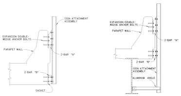
- For a steel beam bridge mounting,
aluminum angles at the bottom are to be fastened to short steel bars
welded to the bridge steel. The bars are to be painted.
- Chloroprene gaskets are to be used to
prevent contact between aluminum sign brackets or support frames and steel
Z-bars or bridge welded-on bars.
- If the sign extends more than 4 feet
(1.2 meters) above or below the attaching Z-bars, intermediate sign
brackets are to be provided.
- For precast beam bridges, aluminum angles
at the bottom are to be fastened to short steel angles and two expansion
double wedge steel anchor bolts are to be used.
- After sign erection, the sturdiness of
the support to bridge attachment should be checked.
630-6 Ground-Mounted Sign Supports
630-6.1 General
This section
provides additional information, generally in the form of checklists, about
various ground-mounted supports. TEM Section 221 addresses general
guidelines about sign supports and TEM Section 240-5 provides additional
design information about ground-mounted supports.
630-6.2 Posts
- Ground-mounted sign supports of the post
type are to be U-channels or square posts of the number specified and be
as shown on SCD TC-41.20.
- Post lengths appearing on the plans are
approximate and the contractor is responsible for determining the exact
length of required posts before cutting to length (CMS Item
630.06A1).
- No. 4 U-channel posts consist of two No.
2 posts bolted back to back. Back-to-back posts are assembled by 5/16 inch
(8 millimeters) steel bolts, lockwashers and nuts on 4 inch (100
millimeters) centers below the groundline and 16 inch (400 millimeters)
centers above the groundline.
- Posts should have a line of paint 42
inches (1.05 meters) from the end, which will be in the earth. The mark
when driven to a distance of 6 inches (150 millimeters) above the ground indicates
a post driven to the proper depth.
- If it is necessary to cut posts to
correct length in the field, the cut end should be covered with two coats
of zinc-rich paint and the cut end driven in the earth or embedded when
required (except for back-to-back posts).
- Posts are to yield when hit and are to
be driven to a depth of 42 inches (1.05 meters). Posts are typically not
to be embedded in concrete unless specified in the plans or ordered by the
project engineer to overcome problems such as adverse soil conditions or
generally prevalent bedrock close to the surface. The driven depth has
been established to assure best yielding characteristics. Deeper depths
are not beneficial in this regard.
- Caution is to be used when driving posts
in areas of buried cable.
- Posts are not to be driven in drainage
ditches.
- Posts are to be installed vertically and
at right angles to the edge of pavement, unless otherwise required.
Exceptions may be NO PARKING signs and STOP signs located at intersections
with curved approaches. In this situation STOP signs should be placed
perpendicular to a line from the viewing point where they are normally
recognized and stopping action would begin.
- Posts are to be driven without bending, distortion
or end mutilation. Mutilation may be prevented by the use of a driving
cap. Posts should be checked to see if the paint mark is 6 inches (150
millimeters) out of the ground after driving.
- Posts located in paved areas are to be
driven through a hole provided by sleeving or core drilling. After
driving, the hole is to be patched with asphalt concrete or approved
bituminous material.
- At locations where posts cannot be
driven, the post may be moved at no additional cost to ODOT, when approved
by the project engineer.
- Typical vertical and horizontal
clearances of signs are shown on SCDs TC-42.10
and TC-
42.20.
630-6.3 “One Way” Sign Supports
Square posts which
are capable of supporting signs at right angles to other signs on the post are
designated as “one-way” sign supports for the most common application. This is
shown on SCD TC-41.50.
630-6.4 Standard Beams
- Ground-mounted sign supports of the
non-breakaway beam type are to be rolled steel, wide flange sections of
the size and weight specified (from the list on SCD TC-41.10).
Non-breakaway beams are to be protected by guardrail or concrete barrier
installed for another purpose. Inspection of beams of the breakaway type
is covered in Section 630-6.5.
- Beam lengths appearing on the plans are
approximate and the contractor is responsible for determining the exact
length of required beams before fabrication (CMS Item
630.06 B).
- Galvanizing is to be inspected in
accordance with Section 630-4.4.
- Beams are to be embedded in a concrete
foundation in accordance with SCD TC-41.10.
- Beams are to be raised into position
with equipment of adequate lifting capacity and used so as to prevent
damage to the galvanizing. The beams are to be braced in a plumb and
square position until the concrete has cured. The age of the concrete
before it is considered cured and before signs are permitted to be erected
is to be according to Section 630-3.4.
630-6.5 Breakaway Beams and Connections
- Ground-mounted sign supports of the
breakaway beam type are to be rolled steel, wide flange sections of the
size and weight specified (from the list on SCD TC-41.10).
- Beam lengths appearing on the plans are
approximate and the contractor is responsible for determining the exact
length of required beams before fabrication (CMS Item
630.06 B).
- Beams are slip base design. Alternate
designs of breakaway connections are permitted.
- Base plates are fabricated to standard
details and welded-on with a bead equal to the beam flange and web
thickness respectively, but not less than 1/4 inch (6.4 millimeters).
- Welding is to be inspected in accordance
with Section 630-4.3.
- Galvanizing of beams is to be inspected
in accordance with Section 630-4.4.
- All portions of beams should be shop
assembled, in accordance with SCD TC-41.10.
- The beam upper portions are to be joined
by the bolts attaching the fuse and hinge plates. The plates are
fabricated to standard details with the fuse plate having notched holes at
the bottom and the hinge plate having unnotched holes. The steel hex head
bolts, with washers under both head and nut, are to have been tensioned in
the shop to the final specified value.
- Torque limiting nuts may be used instead
of conventional nuts on the fuse and hinge plates (SCD TC-41.10,
Note 5).
- The beam lower portions are recommended
to be joined by steel hex head bolts inserted with their nuts uppermost. A
galvanized bolt retainer plate is sandwiched between the base plates. Flat
washers are used under both bolt head and nut as well as under the bolt
retainer plate. For S4x7.7 (S100 x 11.5) beams only, malleable iron
beveled washers are used under bolt head and nuts. Bolts are to be snug
tightened for delivery to the site with final torquing to be done after
erection.
- Torque limiting nuts may be used instead
of conventional nuts on the base plates (SCD TC-41.10,
Note 5). The nuts are to be snug tightened, but not to the point where the
upper area shears away.
- Base plate skewed notches should point
toward the roadway along the path of typical vehicle collision. The skewed
notches of both base plates should match.
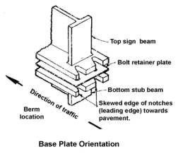
- For beams located in medians, the base
plates should be welded-on upside down as compared with those of beams
located on the right side of the roadway, so the base plate skewed notches
will point toward each roadway along the path of vehicle collision from
either direction of traffic.
- For beams located in medians, fuse
plates are to be used on both sides of the beam.
- For beams located on the right side of
the roadway, fuse plates are to be on the side of the beam facing traffic.
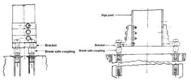
- For the alternate design, special foot
brackets are bolted to the upper beam portion, and four couplings
incorporating a breakable reduced section are connected between the foot
brackets and threaded anchor inserts embedded in the foundation. The
couplings permit use of the design in medians where collision can occur in
either direction of traffic.
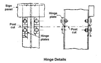
- The alternate design uses four/hinge
plates incorporating a thinned section and bolted where the beam is cut
through just under the sign. The pair of plates on the impact side of the
beam sever upon impact and a pair on the opposite side bend to allow the
beam to swing upward out of the path of the impacting vehicle.
- It is recommended that beams be erected
in a single unit because they are easier to plum, square and brace when
the entire assembly is raised and set in concrete.
- Beams are to be erected in accordance
with the procedure given for non-breakaway beams in Section 630-6.4.
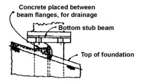
- A sloping concrete foundation top
surface is required on the high ground side to prevent a water pooling
pocket and permit drainage as per SCD TC-41.10.
For the alternate design, the foundation top must be level in the area of
the breakable couplings.
- When a supplemental panel is required
below an extrusheet sign, the panel is fastened by sign backing assemblies
to the parent sign. The panel is to be separated from the sign by the
width of the fuse plate plus 1 inch (25 millimeters). This is to permit
unhindered hinge plate bending in the event of a vehicle collision.
- After the foundation concrete is cured,
base plate nuts are to be loosened in turn and retightened with a torque
wrench in a systematic manner to the specified maximum torque shown in the
table on SCD TC-41.10,
also shown in TEM Table 297-9. Torque wrenches used should be
calibrated daily.
- When torque limiting nuts are used on
base plates, the nuts are to be loosened in turn and tightened in a
systematic manner until the upper area shears away, assuring that the
correct torque has been applied.
- At least four weeks following the
erection of signs on breakaway beams, the breakaway feature is to be
inspected by the contractor for evidence of shifting or loose fasteners.
- All loose fasteners are to be re-torqued
to specified values. Base plate fasteners are to be loosened and
re-torqued even if no shifting or looseness is detected. However, if the
base plate connection was made with torque limiting nuts, re-torquing will
only be required if looseness can be detected. Re-torqued conventional
nuts at this time are to have anaerobic adhesive applied, or as an
alternate, new torque limiting nuts of the proper range may be used.
630-7 Signs
630-7.1 General
Signs should be
inspected when received on the job site if possible, but certainly prior to
erection.
The signs should be
inspected for conformance with the plans, certified shop drawings, catalog cuts
and material specifications.
Flatsheet signs are
typically of aluminum sheet cut into geometric shapes of the size specified.
Dimensions and
thickness are to be as shown on SCDs TC-52.10
and TC-52.20.
Bolt holes are to be drilled or punched (CMS Item
630.04).
Extrusheet signs are
fabricated of aluminum sheet and extrusions, joined by spot welding and
assembled by bolts (SCD TC-51.11).
As an alternative, panels extruded in a single operation may be used (SCD TC-51.12).
Extruded panels and spot welded panels shall not be used in the same sign.
There is to be no appreciable deviation from flatness on the face of an
assembled sign.
Overlay signs are of
aluminum sheet of the thickness specified and used to cover the legend of
extrusheet signs. Signs with overlays should be checked for any loose rivets
holding the overlay sign.
All signs are to be
reflectorized by being covered with the appropriate grade of sheeting. The
sheeting is to be of the correct color, firmly attached and free of tears,
wrinkles, blisters or blemishes.
Sign legend is to be
in accordance with the plans, certified shop drawings and the OMUTCD.
The type of copy on
extrusheet signs is to be as shown on the certified shop drawings. Available
types of copy are listed in TEM Table 297-6.
All signs are to be
identified on the reverse side by decals as described in Section 630-7.4.
Extrusheet signs are
also to be identified by information in a detachable form on the back (see CMS Item
630.04).
630-7.2 Sign Storage
Signs are to be
suitably protected and identified for shipment and storage. Extrusheet signs
are to be kept rigid by backbracing or crating and the sign face covered with protective
material. The backbracing is to extend sufficiently below the sign lower edge
to keep the sign off the ground.
Extrusheet signs and
any flatsheet signs with Type G (high intensity) sheeting are to be stored in a
vertical position.
Signs must be stored
in such a manner that the packaging paper or cardboard material does not get
wet. If the packaging material or slip sheeting should become wet, the paper
should be removed immediately from contact with sign faces to prevent damage to
reflective sheeting on the faces.
In the case of signs
furnished by ODOT for erection by the contractor,
the contractor is to be responsible for the storage and care of the signs after
their transfer (CMS Item
630.08).
630-7.3 Sign Copy
TEM Table 297-6 provides information about the sign copy
used, type, material used, design features, etc.
630-7.4 Sign Identification Decals
All signs are to be
identified on the reverse side by decals of Type F white reflective sheeting
(CMS Item
730.18) with silk screened numerals. Information is to be coded by
punched-out numerals before decal application and is to include: sheeting
manufacturer and year of sign fabrication. At the time of erection, month and
year of erection shall be scratched out by the contractor. This procedure is
described in CMS Item
630.04, which also contains an illustration of the decal. Decals for
overlay signs may be on the front surface.
The following codes
shall be used on the decals to identify the manufacturer of the sheeting.
0 - Avery Dennison
1 - Minnesota Mining and Manufacturing Company (3-M)
2 - Sakai Trading-New York, Inc.
3 - Nippon Carbide Industries (USA)
4 - Morgan Adhesives Company
5 - American Decal and Manufacturing Company
6 - Stimsonite Corporation
7 - Reflexite North America
630-7.5 Sign Erection
630-7.5.1 General
This section
provides information on erection of the signs. Assembly and erection of various
types of overhead sign supports are addressed in Sections 630-4 and 630-5 and
groundmounted supports are addressed in Section 630-6.
630-7.5.2 Ground-Mounted Flatsheet Signs
When erecting
ground-mounted flatsheet signs the following provisions apply:
- Typical vertical and lateral clearances of
ground-mounted flatsheet signs are shown on SCD TC-42.20.
- Flatsheet signs are fastened to posts by
5/16 inch (8 millimeters) hex head steel bolts with a 3/8 inch (10
millimeters) hex ID x 1 1/4 inch (32 millimeters) OD wide washer under the
bolt head and using a lock washer and hex nut. For U-channel posts, at
each bolt a bearing plate behind the sign is used to reinforce the sign,
as indicated on SCD TC-41.20.
The hardware and bearing plates are furnished with the signs.
- Posts supporting groupings of flatsheet
signs in multiple arrangements will require the use of sign backing
assemblies made up of bolted together short sections of posts. Sign
backing assemblies are furnished with the signs unless separately
itemized.
- Flatsheet signs mounted so as to be read
by motorists using bridges are to be erected on special steel posts in
accordance with SCD TC-41.40.
- Street Name signs are to be erected on
square supports in accordance with SCD TC-
41.40.
630-7.5.3 Ground-Mounted Guide Signs
When erecting
ground-mounted Guide Signs the following provisions apply:
- Typical vertical and lateral clearances
of ground-mounted Guide Signs are shown on SCD TC-42.10.
- Mounting clips and other attachment
hardware is to conform with SCD TC-51.11.
- Supplemental panels erected under
ground-mounted Guide Signs mounted on nonbreakaway beams are to be
fastened directly to the beams. The panel is to be separated from the
Guide Sign by 1 inch (25 millimeters) to conform with SCD TC-42.10.
When the panel is too short to reach between the beams, the panel may be
fastened to the Guide Sign by sign backing assemblies.
- Supplemental panels erected under
ground-mounted Guide Signs mounted on breakaway beams are to be fastened
to the Guide Sign by sign backing assemblies. The panel is to be separated
from the Guide Sign by the width of the fuse plate plus 1 inch (25
millimeters).
- Exit Panels erected above Guide Signs
are to be attached by sign backing assemblies furnished with the Exit
Panel.
- The signs should be checked after
erection to verify that the beams extend to the top of the signs and that
the signs are horizontal and the clearances satisfactory.
630-7.5.4 Overhead Signs
When erecting
overhead signs the following provisions apply:
- The clearance above the roadway for the
bottom of overhead signs is to be a minimum of 17 feet (5.2 meters), or as
shown on the plans.
- Overhead signs are to be vertical or
horizontal regardless of the sag of supporting messenger wire, mast arm
rise, chord camber or overpass slope.
- Signs erected on span wire supports are
to be attached in accordance with SCD TC-
17.10.
- Signs erected on single arm supports
(SCD TC-16.20)
are to be installed so their bottom edge is at the same elevation.
Sufficient adjustment for this purpose is provided by the two pair of
slotted holes in the sign brackets for the attachment of the arm clamps.
The clamps are to be tightened sufficiently to prevent sign rotation about
the arm.
- Signs mounted on semi-overhead supports
(SCD TC-9.10)
are to be erected so that their edge clearance from the curb line is at
least 2 feet (0.6 meter).
- Extrusheet signs over 8 feet (2.4
meters) in height may be delivered in two pieces for assembly in the field
(CMS Item
630.04).
- Guide Signs erected on supports with two
arms are to be centered vertically.
- Mounting clips and other attachment
hardware is to conform with SCD TC-51.11.
- Signs mounted on center-mount supports
(SCD TC-9.30)
may be mounted laterally on the support in an eccentric position when
required by the plans. However, a minimum of 2 feet (0.6 meter) of sign
length is to remain to one side or the other of the vertical member
centerline.
- Overlay signs erected in the field over
existing Guide Signs are to be attached by blind rivets at spacings as
required in CMS Item
630.04.
- Flatsheet signs used in connection with
signals supported by span wire are fastened to the messenger wire by
special attachments in accordance with SCD TC-41.41.
- Flatsheet signs used in connection with
signals supported in a swinging condition on mast arm supports are fastened
to the arm by a special attachment in accordance with SCD TC-41.41.
- Exit Panels erected above Guide Signs
are to be attached by sign backing assemblies furnished with the Exit
Panel.
630-7.6 Sign Inspection
After sign erection,
the contractor is to inspect all signs under both day and night conditions. Any
necessary adjustments in lateral position or orientation to correct visibility
deficiencies are to be made to the satisfaction of the project engineer (CMS Item
630.13).
Overhead Guide Signs
should typically be centered over the lane(s) to which they apply. Down arrows
on the signs should normally be centered over the proper lane as viewed by the
motorist.
The maximum
displacement of a down arrow from the center of a lane should not be more than
2 feet (0.6 meter).
Overhead Guide Signs
situated on curved roadways and incorporating down arrows may have the arrow(s)
adjusted within the sign and/or the entire sign moved laterally so the arrows
when seen from a typical viewing distance on the curve will appear to be over
the proper lane(s).
Night conditions
inspection is to assure that each sign has visible and uniform reflectivity.
Any signs not having proper reflectivity should be noted and cleaned or
replaced by the contractor.
630-8 Sign Lighting
630-8.1 General
Guidelines and
design information on sign lighting are addressed in TEM Sections 212 and
240-7.
This section
provides additional information about what to look for when installing sign
lighting.
- Check certified shop drawings, catalog
cuts, etc. for luminaires, ballasts, switches and enclosures.
- Luminaires for mercury vapor sign
lighting are to comply with CMS Item
731.01 and are to consist of a housing containing a reflector, lamp
socket, wiring and a door containing a glass lens or refractor, meeting
the following requirements:
- The housing is to be adequately
reinforced cast aluminum with a natural finish or painted gray.
- The reflector is to be highly
reflective aluminum.
- The lamp socket is to be a porcelain
shrouded mogul screw with lamp grips and a large center spring providing
firm contact with a lamp base.
- The door is to be an aluminum frame
either cast with a natural finish or a formed extrusion with an anodized
finish. The door is to be hinged securely to the housing and provided
with a spring loaded latch. Hinges are to be stainless steel and designed
so that unintentional door separation is impossible. Latches are to be
stainless steel and are not to require tools for opening.
- A flexible readily removable gasket is
to be attached to the housing or door so a waterproof seal is formed when
the door is closed and the gasket compressed. The glass lens is to be
mounted within the door and sealed with elastic cement or a gasket.
- The glass lens is to be borosilicate or
equivalent, able to withstand hail or the thermal shock of freezing rain.
- Drainage weep holes are to be provided
in the housing or door depending upon the luminaire’s bottom or top
position on a sign.
- Mercury vapor lamp sizes are to be as
specified. Ballast type is to match the specified lamp wattage. Lamp watts
and ANSI code are shown in Table 297-11 from SCD TC-31.21.
- Sign lighting is to be controlled by a
disconnect switch within an enclosure. The switch is to be a two-pole
minimum, single throw, fused safety disconnect type rated at 600 volts and
30 amperes (CMS Item
631.06). The fuse size is to be as specified. A solid neutral bar is
to be provided.
- The enclosure is to be weatherproof and
lockable, complying with NEMA standard Type 4 ICS 1-110.15. Enclosure size
is to be as specified (See SCD TC-32.10).
- Each enclosure is to be furnished with
at least one padlock. Padlocks are to have a corrosion resistant body and
a corrosion proof steel shackle. All padlocks for a project are to be
keyed alike from an appropriate master key number obtained by the
contractor from the maintaining agency.
- Sign service to the enclosure is to be
according to the plans. Service wiring cable size is to be as specified, single
conductor rated at 600 volts and not less than Number 4 AWG (CMS Item
631.04). Sign service underground from a pull box to a foundation
mounted support, or to a support mounted on a concrete median barrier, is
shown on SCD TC-32.10.
Sign service from a direct drop is shown on SCD TC-32.11.
- Sign wiring from the disconnect to the
luminaires is to be the size specified, single conductor rated at 600
volts and not less than Number 10 AWG (CMS Item
631.05). The wiring is to be fully protected within enclosures,
support interiors, junction boxes, rigid or flexible conduit and luminaire
housings. Wiring is to be continuous from the disconnect switch to a
junction box mounted on the sign support or overpass structure. The
junction box is to permit disconnection of wiring when a sign and its
lighting equipment is removed as a unit. A junction box is to be installed
for each sign. Wiring is to be continuous from the junction box to the
first luminaire on a sign and continuous between additional luminaires on
the sign.
- Luminaire ballast is to be located
within the luminaire (integral) or in a weatherproof housing attached to
or beside the luminaire (contiguous). Wiring to the ballast is to be
continuous with permitted disconnection at the sign support junction box (see
paragraph 8).
- The wiring routing for wired signs is to
be as shown on SCD TC-31.21.
- Luminaire supports complying with SCD TC-31.21
are specified for new installations. Support arms are of welded tubular
design incorporating an attachment flange and a luminaire support plate.
The arms are bolted to a continuous rectangular galvanized steel tube
forming the lower portion of the sign’s glare shield. The face of the
rectangular tube is to be covered with non-reflective sheeting complying
with CMS Item
730.20 so as to match the color of the glare shield sheeting. Support
arms are not to be mounted upside down or in any other manner than that
permitted by the SCD.
- Luminaires are to be adjusted to a
proper aiming angle according to the manufacturer’s instructions and
inspected at night to determine if they are providing uniform illumination
to the sign face.
630-8.2 Sign Lighting Inspection and Testing
- In accordance with CMS Item
631.11, sign lighting and electrical signs are to meet the
requirements of the following tests as required by CMS Item
625.19 and performed by the contractor:
During the ten-day performance test, failure of lamps, ballasts and transformers may be corrected by replacement of the faulty component but will not require restart of the entire test period.
- The contractor should perform a circuit
test on all sign lighting cable and wire conductors to determine if there
are any short circuits, cross circuits or other improper connections.
Circuit testing may be done in accordance with Section 632-11.4 .
- The test results are to be reported to
the project engineer in the test information required by CMS Item
625.19. The test results should be documented.
- During the ten-day performance test, a
night inspection is to be performed by the contractor and final
adjustments made to sign lateral positions and the aiming angle of
luminaires to the satisfaction of the project engineer (CMS Item
631.11). The adjustments are to eliminate excessive brightness and
glare and to obtain optimum sign face reflected brightness, uniformity of
illumination, visibility and legibility.
- Following successful completion of a
ten-day performance test and after there has been a partial or final
acceptance of the project, the contractor should turn over to the project
engineer all manuals, diagrams, instructions, guarantees and related
material. The project engineer should transfer the material to the
maintaining agency. For ODOT-maintained
signs, the material should be given to the appropriate ODOT District Office.
- After the project has been accepted by ODOT, the project engineer should immediately
notify the maintaining agency that as of a certain exact time and date,
the agency is responsible for the maintenance.
630 Supplemental Information
Please refer to the Traffic Engineering Manual for a complete list of forms, supplementary information, and updates
Table 297-9. Bolt Size and Maximum Torque for Beams
|
Beam |
|
Bolt Size |
Maximum Torque |
||
|
Type |
Size |
|
|||
|
Inches |
mm |
|
in (mm) |
in-lb (N-m) |
|
|
S4 x 7.7 |
4 x 2 5/8 |
102 x 67 |
|
13 (1/2 ) |
22.6 (200) |
|
W6 x 9 |
5 7/8 x 4 |
149 x 102 |
|
13 (1/2) |
22.6 (200) |
|
W10 x 12 |
9 7/8 x 4 |
244 x 102 |
|
19 (3/4) |
85 (750) |
|
W8 x 18 |
8 1/8 x 5 ¼ |
206 x 133 |
|
19 (3/4) |
85 (750) |
|
W10 x 22 |
10 1/8 x 5 ¾ |
257 x 146 |
|
25 (1) |
150 (1325) |
|
W12 x 30 |
12 3/8 x 6 ½ |
314 x 165 |
|
25 (1) |
150 (1325) |
Table 297-10. Bolt Tension
|
Bolt Tension |
|||||
|
Bolt Size |
80% Proof Load |
Proof Load |
|||
|
inches (mm) |
lbs. (kg.) |
lbs. (kg.) |
|||
|
1/2 |
(13) |
9,700 |
(4400) |
12,100 |
(5490) |
|
5/8 |
(16) |
15,400 |
(6990) |
19,200 |
(8710) |
|
3/4 |
(19) |
21,900 |
(9930) |
28,400 |
(12,900) |
|
7/8 |
(22) |
31,400 |
(14,200) |
39,300 |
(17,800) |
|
1 |
(25) |
41,200 |
(18,700) |
51,500 |
(23,400) |
|
1 1/8 |
(29) |
45,200 |
(20,500) |
56,500 |
(25,600) |
|
1 1/4 |
(32) |
57,400 |
(26,000) |
71,700 |
(32,500) |
|
1 3/8 |
(35) |
68,400 |
(31,000) |
85,500 |
(39,800) |
|
1 1/2 |
(38) |
83,100 |
(37,700) |
104,000 |
(47,200) |
Figure 298-25. Foundation Excavations