ITEM 638 WATER MAINS AND SERVICE BRANCHES
638.01
Description
638.02
Materials
638.03
Notification
638.04
Excavation
638.05 Pipe
Bedding
638.06 Pipe Laying
638.07 Pipe
Joints
638.08
Backfilling
638.09
Hydrostatic Tests
638.10
Disinfection of Completed Water Work
638.11 Steel
Pipe Encasement
638.12
Polyethylene Encasement
638.13 Valves
and Equipment
638.14 Fire
Hydrant
638.15 Fire
Hydrant Adjusted
638.16 Service
Branches
638.17 Meter
and Chamber Removed and Reset
638.18 Valve
Box and Service Box Adjusted to Grade
638.19 Method of
Measurement
638.20 Basis of
Payment
638.01 Description. This work consists of
constructing water mains and service branches, including fire hydrants, water
meters, corporation stops, service boxes, service stops,
valves, fittings, and valve boxes, and includes:
A.
Excavation for items and preparation of the foundations, necessary for placing
water mains and service branches, including fire hydrants, water meters,
corporation stops, service boxes, service stops, valves, fittings, and valve
boxes.
B.
Furnishing and placing bedding and backfill.
C.
Constructing and subsequently removing all necessary cofferdams, bracing, cribs
and sheeting.
D.
Pumping and dewatering.
E.
Providing all joints as shown on the plans.
F.
Furnishing and installing all necessary bends and branches.
G.
Furnishing and installing all necessary tracer tape.
H.
Joining to existing and proposed appurtenances as required in the project
plans.
I.
Performing all necessary test (leakage test,
disinfections, hydrostatic).
J.
Restoration of disturbed underground facilities.
K.
Constructing all required blocking and wedging and/or thrust blocking.
L.
Furnishing and installing all necessary restraining of joints and fittings.
M. Cutting and plugging as required existing
water mains to be abandoned.
Use removed or
excavated materials in the Work when the material conforms to the
specifications; if not, then recycle or dispose of the material according to 105.16 and 105.17.
638.02 Materials. Furnish materials conforming to:
Pipe, joints, and fittings.
Ductile iron pipe, joints,
and fittings........................ 748.01
Polyvinyl chloride (PVC)
pipe,
.... joints,
and fittings................................................ 748.02
Polyethylene (PE) service
.... branches
and fittings........................................... 748.03
Copper service branches
and fittings....................... 748.05
Steel pipe
encasement.............................................. 748.06
Polyethylene
encasement......................................... 748.07
Valves and equipment.
Gate valve and valve
box......................................... 748.08
Inserting valve and valve
box.................................. 748.09
Cutting-in sleeve, valve
and valve box..................... 748.10
Tapping sleeve, valve and
valve box........................ 748.11
Tapping saddle and
corporation stop....................... 748.12
Service stop
and service box.................................... 748.13
Meter, setting, stop and
chamber............................. 748.14
Fire
hydrant............................................................. 748.15
Miscellaneous.
Granular
Material..................................................... 605.02
Disinfectant...........................................................
AWWA
Pipe bedding .......................................................
611.02 H
Concrete, Class
QC-Misc.................................. 499 and 511
Soil and granular
embankment................................. 203.02
Structural backfill, Types
1, 2, and 3....................... 703.11
Mortar...........................................................................
602
The
Engineer will allow Type 3 structural backfill, conforming to 703.11, to be used as bedding below the pipe
only when pumping operations do not control severe ground water problems.
Place at least 12 inches (300 mm) of Type 1 structural backfill on top of the
Type 3 structural backfill to prevent piping.
The
metric equivalent pipe size may vary with material type for the same English
size pipe.
638.03 Notification. Notify the Engineer and
maintaining agency of the following:
A.
The dates scheduled for testing and for disinfections of mains and branches.
B.
Any clearances less than 1 foot (0.3 m) between new mains and existing pipes,
sewers, and structures.
638.04 Excavation. Excavate according to Item 611 with the following additions:
A.
Excavate the trench a suitable distance in advance of pipe laying
to ensure proper clearance between the waterline and any utility crossing or
underground structure. Suitably brace and support utilities and
structures.
B.
Excavate the trench walls vertically up to the top of the pipe. Ensure
that the clearance on either side of a pipe is a minimum of 6 inches (150 mm)
and a maximum of 12 inches (300 mm). In paved areas, neatly line cut
the pavement at the surface a distance of at least 12 inches (300 mm)
beyond the trench side and remove paving material.
C.
Furnish cover over pipes of 5 feet (1.5 m) unless otherwise shown on the plans.
D.
Pile excavated material in a manner that will not endanger the work or obstruct
sidewalks and driveways. Keep gutters clear or make other satisfactory
provisions for drainage. Do not obstruct natural water-courses.
E.
Furnish holes for pipe bells at each joint, but make them no longer than
necessary for joint assembly and assurance that the pipe barrel will be flat on
the trench bottom.
F.
Furnish, place, and maintain such sheeting and bracing as may be
required. Immediately backfill and compact voids appearing outside of
sheeting. Notify the maintaining agency of sheeting and bracing left in
place. Do not remove sheeting and bracing until sufficient backfill has
been placed to provide ample support to the sides of the excavation. When sheeting is left in place, cut it off at least 2 feet (0.6 m)
below the proposed finished surface or subgrade in paved areas.
The Department will pay for sheeting and bracing it orders to be left in place
as a separate item of the work.
638.05 Pipe Bedding. Where specified, provide structural
backfill for bedding according to Item 611 except the
bedding is 4 inches (100 mm) thick.
A. Inspection. Inspect water mains and auxiliary equipment
upon delivery in the field to ensure proper working order before installation.
B. Trench Dewatering. Where water is encountered in the trench,
remove it during pipe-laying operations and maintain the trench water free
until the ends of the pipe are sealed and provisions are made to prevent floating
of the pipe. Do not allow trench water or other deleterious materials to
enter the pipe at any time.
C. Pipe Clearance. Lay pipe at least 12 inches (300 mm) from any
structure or underground utility, and maintain a minimum 10-foot (3 m) horizontal
separation from sanitary sewers.
D. Existing Systems. Do not operate any valve or other control on
the existing system. The maintaining agency will operate all valves,
hydrants, air valves, and service stops.
E. Pipe Handling. Handle pipe in a manner that will prevent
damage to the pipe, pipe lining, or coating. Load, unload, and place pipe
and fittings using hoists and slings in a manner that will avoid shock or
damage. Do not drop, skid, or roll pipe or fittings against other pipe.
F. Pipe Cutting. Whenever it becomes necessary to cut a length
of pipe, make the pipe ends square with the longitudinal axis of the pipe and
otherwise smooth so that good connections can be made. Cut pipe using
cutters recommended by the manufacturer. Do not cut ductile iron pipe
with an oxyacetylene torch. File or grind field-cut pipe lengths to
obtain a chamfer on the outside of the pipe, according to the manufacturer’s
recommendations. Remove rough or sharp edges from the cut end.
G. Pipe Laying. Ensure that pipe and fittings are clean when
laid. Take precautions to prevent floating. Place the pipe on the
trench bottom or bedding. After the pipe has been aligned and jointed,
and thrust blocking has been placed, secure the pipe in place with approved
backfill material. At times when pipe laying is not in
progress, close the open ends of the pipe with a watertight plug.
H. Pipe Laying on Curves. If the pipe is shown curved on the plans,
construct the curves by special fittings or by deflecting the joints according
to the manufacturer’s recommendations. Do not make joint deflections at
valves.
When rubber-gasketed pipe is laid on a curve, joint the pipe in a
straight alignment and then deflect it to the curved alignment. Make trenches
wider on curves for this purpose.
I. Pipe Laying
Where Earth Grading is Necessary.
Where a pipe is to be placed within an embankment or the top of the pipe is
above the existing ground, construct the embankment to at least 6 inches (150
mm) above the top of the pipe before trenching for the pipe. Excavate the
trench to the minimum width necessary for the proper placing and backfilling of
the pipe.
J. Tracer Tape. Install tracer tape over copper and
non-metallic water lines, including service lines. Place the tracer tape
approximately 1 foot (0.3 m) above the top of the line and extend the tape for
the line’s full length. Use tracer tape that is a detectable type and is
marked “WATER.”
K. Blocking and Wedging. Lay fire hydrants, valves, and fittings on
hardwood blocks and hold them in position by hardwood wedges. Bed blocks
firmly in the bottom of the trench with uniform bearing and with the long
dimension of the block perpendicular to the pipe barrel. Ensure that the
blocks are level across the trench and that the proper number of blocks are
placed one upon the other to bring the fittings to the required grade for
jointing.
L. Thrust Blocking. Furnish plugs, caps, tees, hydrants, and elbows
or bends having a deflection of 11 1/4 degrees or greater with concrete thrust
blocking, unless suitably restrained joints are provided. Construct the
thrust blocking by placing concrete Class QC-Misc between firm original
undisturbed earth and the fitting to be anchored. Place and shape the
thrust blocking in a manner satisfactory to the Engineer with the thrust force
contained by the blocking. Place the hardwood blocks between the plugs,
caps, and hydrants, and the thrust blocking. Place the thrust blocking so
that it allows for pipe and joint accessibility or repair.
M. Restrained Joints and Fittings. Where conditions at an elbow, tee, or bulkhead
are not conducive to the use of thrust blocking, restrain push-on or mechanical
joints and fittings by bent or straight tie-rods, straps, clamps, or other
devices, with required hardware. Protect the devices against corrosion by
the application of an asphalt coating. Restrain mechanical joints by a
wedge action type joint restraint with twist-off nuts. If polyethylene
encasement is specified, ensure that the encasement covers the entire
assembly. The Contractor may use restraining devices instead of thrust
blocking when approved by the Engineer.
638.07 Pipe Joints. Furnish ductile iron pipe
and cast iron or ductile iron fittings with push-on joints, mechanical joints,
boltless-restrained joints, or ball-and-socket joints. Furnish joints
with all accessories and install them according to the manufacturer’s
recommendations. During any construction where the outside temperature is
below 40 °F (4 °C), keep rubber gaskets and lubricants in a heated area to at
least 40 °F (4 °C) until used. Maintain gaskets in a flexible condition
until placed in the bell or on the spigot of the pipe.
638.08 Backfilling. Complete backfill from the
pipe grade to the finished grade, or to the subgrade surface in paved
areas. Furnish and compact backfill material for water mains and
appurtenances under pavements in the same manner as for 611 non-plastic
Type B conduits. Furnish and compact backfill material for water mains
and appurtenances not under pavements in the same manner as for 611 non-plastic Type C conduits.
If
hydrostatic testing is performed before the backfilling operation is completed,
complete the portion of the backfill from pipe grade to the centerline of the
pipe, fittings, or appurtenances and place sufficient backfill material over
the pipe barrel between joints to prevent movement.
Place
sand cushions at least 12 inches (0.3 m) thick between the pipe and existing
pipelines or other conduits when encountered during construction and as
directed by the Engineer.
Immediately
after completion of the backfilling, restore the site according to Item 611.
638.09 Hydrostatic Tests. Apply a
hydrostatic test to the whole system or to all individual valved-off
sections of the mains where work has been performed. Perform the
hydrostatic tests according to of AWWA, except make the test pressure greater than 150
pounds per square inch (1000 kPa). Ensure that
the quantity of water lost from the main does not exceed the number of gallons
(liters) per hour as determined by in AWWA or by the following formula:
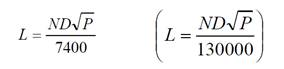
where:
L = allowable
leakage, in gallons (L) per hour
N = number
of joints in the length of pipe tested.
D = nominal
diameter of the pipe, in inches (mm)
P = average
test pressure during the leakage test, in pounds per square inch (kPa)
638.10 Disinfection of Completed Water Work. After
passing the hydrostatic testing, disinfect the completed water work according
to AWWA.
Make
all necessary taps and furnish all equipment and labor required for the
disinfections. Obtain the Engineer’s approval of the time and the section
of line to be disinfected.
638.11 Steel Pipe Encasement. Furnish
and install a steel casing of the diameter and wall thickness shown in the
plans.
Make
any necessary excavation to install the steel casing. Obtain the
Engineer’s approval for the method of any boring or jacking operation. If
placing the steel casing in an open cut trench, place it according to 638.05 and 638.08.
Join
the casing pipe together with a full-circumference weld conforming to 513.21.
Ensure
that the inside diameter of the casing allows the water main to be removed
without disturbing the casing or roadbed. Ensure that the inside diameter
of the casing is at least 2 inches (50 mm) greater than the largest
outside diameter of the water main joints or couplings for carrier pipe that is
less than 6 inches (150 mm). Ensure that the inside diameter is at least
4 inches (100 mm) greater than the largest outside diameter for carrier pipe 6
inches (150 mm) in diameter and over.
Install
the main in the casing on hardwood blocking or stainless steel chocks designed
to remain fixed in position. The Contractor may install polyvinyl
chloride water main using casing insulators. Close both ends of the
casing with mortared 4-inch (100 mm) bricks or a concrete bulkhead.
638.12 Polyethylene Encasement. Lay ductile iron pipe with a polyethylene encasement as shown on the plans. Install pipe and polyethylene encasement according to ANSI/AWWA
638.13 Valves and Equipment.
Upon delivery at the work site, open valves to prevent the collection of water
in the valve. Clean the interiors of valves of all foreign matter, and
inspect them in both the open and closed position before installation.
Installation
methods for valves and equipment include the following.
G.
Meter, Setting, Stop, and Chamber. This
pay item is for meters that are to be installed in frost-proof chambers.
Set the chamber on hardwood blocks. The maintaining agency shall furnish
meters unless otherwise indicated by the plans. Do not transmit shock or
stress to the meter body.
638.14 Fire Hydrant.
The item includes excavation and furnishing and installing a new fire hydrant
complete with proper jointing, blocking, and backfilling as outlined below and
all other incidental work necessary to complete this item of work. The
Department will pay for all hydrant branches, gate valves, and valve boxes
required to perform the work separately.
A.
Excavation and Drainage Pits. Excavate
according to 638.04.
Excavate a drainage pit 2 feet (0.6 m) in diameter and 3 feet (1 m) deep below
the hydrant and fill it with granular material.
B.
Setting Fire Hydrants. Provide a 3-foot
(1 m) minimum radius unobstructed area around all hydrants. Set the
sidewalk flange 2 inches (50 mm) above finished grade. Set hydrants on
hardwood blocks according to 638.06.K.
Provide thrust blocking according to 638.06.L.
Cover
any hydrant not in service with a burlap or sturdy opaque plastic bag.
C.
Fire Hydrant Connections. Construct
hydrant branches using a section of ductile iron pipe from the main to the
hydrant, and include a gate valve and valve box set vertically and placed in
the line as indicated. Locate the valve a minimum of 3 feet (1 m) from
the hydrant streamer connection.
D.
Gate Valve and Valve Box. Provide gate
valve and valve boxes for hydrant branches conforming to 638.13.
638.15 Fire Hydrant Adjusted. This
item includes installing fire hydrants as described below complete with proper
jointing, blocking, backfilling as outlined and all other incidental work
necessary to complete this item of work. The Department will pay for all
hydrant branches, gate valves, and valve boxes required to
perform the work separately.
B.
Fire Hydrant Removed and Reset. Where
existing hydrants are indicated for removal, provide adequate support for the
hydrant before disconnecting it and resetting it in the new location. Cap
the existing branch line, and install adequate thrust blocking to brace the cap
according to 638.06.L, unless
the line is to be abandoned. Construct a new main tee, a new pipe branch,
a new gate valve with valve box, with thrust blocking, and a drainage pit for
the reset hydrant items. Adjust the valve box to the finished surface at
the new location by raising or lowering the top portion and furnishing an
extension section if needed.
638.16 Service Branches.
Furnish and install service branches, either pipe or tubing and fittings, as
necessary, or as shown on the plans including the removal of the existing
service branches or service boxes, as required according to the following
situations. Tapping saddles, corporation stops, service stops, and service
boxes, if required, are separate from this item:
638.17 Meter and Chamber Removed and Reset. Remove and reset existing water meters and
chambers as specified in 638.13.G. Remove existing chambers. Disconnect
existing meters, and replace them with suitable connections if necessary.
Reconnect the meters at new locations.
638.18 Valve Box and Service Box Adjusted to Grade. Raise or lower existing valve boxes and
service boxes to grade or the reuse of existing service boxes.
638.19 Method of Measurement.
The Department will measure Water Main, Ductile Iron Pipe and Water Main,
Polyvinyl Chloride Pipe and Fittings by the number of feet (meters) of each
constructed.
The
Department will measure Polyethylene Encasement by the number of feet (meters)
of covered pipe.
The
Department will measure Meter and Chamber Removed and Reset by the number of
each.
638.20 Basis of Payment.
The Department will pay for accepted quantities at the contract unit prices as
follows:
638
Foot
(Meter)
___ inch (___ mm) Water Main,
Polyvinyl Chloride Pipe and Fittings,
ASTM SAR ___ or AWWA Class ___
638
Foot (Meter)
___ inch (___ mm) Copper Service Branch
638
Foot
(Meter)
___ inch (___ mm)
638
Foot
(Meter)
___ inch (___ mm)
Polybutylene Service Branch
638
Each
___ inch (___ mm) Gate Valve and Valve Box
638
Each
___ inch (mm) Inserting Valve and Valve Box
638
Each
___ inch (mm) Cutting-In Sleeve,
Valve and Valve Box
638
Each
___ inch ´ ___ inch (___ mm ´ ___ mm)
Tapping Sleeve, Valve and Valve Box
638
Each
Meter, Setting, Stop and Chamber
638
Each
___ inch (___ mm) Fire Hydrant
638
Each
Fire Hydrant Extended and
Adjusted to Grade
638
Each
Fire Hydrant Adjusted to Grade
638
Each
Fire Hydrant Removed and Reset
638
Each
Fire Hydrant and Gate Valve
Removed and Reset
638
Each
Fire Hydrant Removed and Disposed Of
638
Each
Valve Box Adjusted to Grade
638
Each
Service Box Adjusted to Grade
638
Each
Meter and Chamber Removed and Reset
638
MBF
Sheeting and Bracing
(Cubic
Meter)
Ordered Left In Place