Approved Guardrail End Treatments 
The following products are roadside guardrail end treatments. They are not to be used if the backside is located in the clear zone of other traffic, as in a median or a gore. They are normally attached directly to Type 5 guardrail runs, but connections to other types of barrier are acceptable, but not necessarily preferred, if the appropriate transition (BTA) is utilized.
FHWA cautions about using gating end terminals without considering the terrain in an area directly behind the end terminal. All products listed in this section are gating. See L&D Section 602.1.4.
For each ODOT Type system, all products and product configurations listed in that Type are considered equal. Contractors are free to chose which system they install from among the approved listing. Guardrail End Treatment Anchor Assemblies used in Ohio are:
- Type B - Flared (L&D Section 603.3.2)
- Type E - Tangential (L&D Section 603.3.3)
Flared Anchor Assemblies - ODOT Type B
L&D Section 603.3.2, Plan Note R112, and SCDs GR-2.3, GR-5.1, GR-5.2, GR-6.1 & GR-6.2.
ODOT Approved Type B devices, the approved shop drawings, and drawing dates are:
(1) FLEAT, Road Systems, Inc.
FLT-M (4/16/98) - The FLEAT is a seven post (all posts are wood CRT) TL-3 end terminal with an four foot straight offset flare, or
FLT Hinged CRT (5/4/06) - This is an alternate FLEAT configuration (posts 1 & 2 are steel hinged, the remaining five posts are CRT), that also has straight flare.
FLT-SP (3/30/09) - A 7 post option using standard steel posts.
(2) SRT-350, Trinity Industries, Inc.
SS 425M (6/21/97) - The SRT-350 is the older nine post system, while
SS 444 (7/12/99) is a simplified eight post terminal, both of which are installed on a parabolic flare.
Tangential Anchor Assemblies - ODOT Type E
L&D Section 603.3.3, Plan Note R113, and SCDs GR-2.3 & GR-5.3
ODOT Approved Type E devices, the approved shop drawings, and drawing dates are:
(1) ET-2000 Plus, Trinity Industries, Inc.
The ET is approved in several variations:
SS-142 (4/12/00) a similar ET with the "Plus" extruder head,
SS-141 (5/22/00) the Hinged Breakaway Post (posts 1-4) option,
SS-158 (5/22/00) a HBA variation using 12'6" (instead of 25') rail panels
SS-330 (3/28/06) a four foundation tubes for posts 1 through 4, with the first two six feet long, and the second two 4 feet, 6 inches. None of these tubes have soil plates. The other four posts are wood CRT.
SS-373 (1/20/09) ET-Plus with 7 SYT Posts and 1 HBA Post, with either 25 foot or 12.5 foot rail panels.
(2) SKT, Road Systems, Inc.
SKT-4M, (12/11/97) The approved SKT is a nine wood post system, and
SKT Hinged CRT (4/30/06) - An alternate configuration (posts 1 through 4 are steel hinged, the remaining five post sare CRT).
SKT-SP (3/30/09) - A 7-post option using standard steel posts.
Specifying Impact Attenuators
Impact Attenuators, also known as crash cushions, are generally used to shield motorists from rigid structures like bridge piers and end of concrete barriers. Since impact attenuators can be installed in two sided situations, they are idea for median or gore applications.
Types
ODOT currently specifies three types of impact attenuators:
- Type 1 - Wide Median (L&D Section 603.4.1)
- Type 2 - Narrow Median or Gore (L&D Section 603.4.2)
- Type 3 - Reusable/Self-Restoring (L&D Section 603.4.3)
The Type 1's usually connect to barrier guardrail runs, while the other types connect to concrete barrier. Connections to other type of barriers are acceptable if the appropriate transitions are utilized and properly specified in the plans.
Required Plan Details
The Types 2's & 3's need to be sufficiently detailed in the plans so that the vendors and contractors are able to prepare a knowledgeable bid. Each specified impact attenuator location must be noted as to the:
- Roadway Design speed
- Hazard width
- Hazard location (median, gore, or roadside)
Design Considerations
Additionally, the designer should note for each occurrence of the impact attenuator if the following conditions exist at each site. But in reality the designer should attempt to remove these features from the plans. And it probably is best if these conditions are designed out of project plans on new construction.
- Do curbs exists, and what is their height?
- Is there excessive cross slope, greater than 5 to 8 percent?
- Unique characteristics of site, like expansion joints?
- Is the system to replace an existing system? What components will be retained?
- Type of nosing desired (frangible or more expensive reusable).
Additional Plan Details
Each of the Type 2 (and to a lesser extent Type 3) products have a wide variety of related units (families), typically covering various design speeds (number of bays) and protected widths. In addition to the information listed previously, the designer should also identify on the project plans, any additional items needed to construct a complete device. For each Type 2 or Type 3 specified on the plan this includes:
- Foundation Type: (asphalt, concrete, bridge deck, etc). If on a bridge deck, note location of bridge joints. Concrete foundations, either a reinforced, or a thicker unreinforced design, are recommended for permanent installations.
- Backup Support: A standard 24 inch wide reinforced vertical faced concrete backup for impact attenuators is detailed on SCD RM-4.6 as a reinforced end section. Otherwise, specify an independent stand-alone anchorage like the product's own reinforced concrete backup, or its tension strut backup.
- Transition: Direction (bidirectional or unidirectional) and type of connection (vertical end, NJ cross section, guardrail, or other). This information identifies to the bidding contractor the necessary connecting parts needed to install the product to NCHRP Report 350 criteria.
Foundations, Backups and Transitions are location specific options and are part of the pay items for the impact attenuator, but the additional items have to be noted on the plans for each unit specified so the contractor is able to prepare a bid.
Transition to Concrete Barrier
The preferred standard connection from Single Slope Concrete barrier to Type 2 & Type 3 are the End Sections are shown on SCD RM-4.6. The End Sections are reinforced and transition from the single slope to a 24 inch wide vertical end section capable of receiving a 24 inch wide impact attenuator. If the project has existing NJ Safety Shape barrier, a Plan Insert Sheet shows a similar vertical faced end section. If the concrete end section is wider, the designer should individually detail a wider end section and specify an impact attenuator of an appropriate width.
Sometimes the concrete barrier end does not have a vertical face, but has the cross sectional shape of the barrier. If it is adequately reinforced this end could be the backup support for the impact attenuator, otherwise use the product's method for backup support (concrete backup or tension strut). Designers should adequately describe this barrier termini so contractors may appropriately bid an impact attenuator unit that has sufficient backup support and the appropriate transition barrier element from the impact attenuator to the connecting barrier.
Problems Encountered by Generically Specifying Proprietary Products
Another consideration the designer must make is whether design conditions or available space for the impact attenuator will accept all of the approved products. There are two likely scenarios for this to happen. In both cases, proper detailing of the design speed, hazard width and available footprint for the Type 2 (or Type 3) is sufficient to place the selection burden on the contractor, without the designer having to take the time to differentiate between the various products.
- Product Availability One place this would happen is at the edges of the product envelope where one vendor may not have an available product, such as for high speeds (70 mph) or very wide hazard protection (120 inches). As long as the design speed and hazard widths are labeled on the plans for each occurrence of an impact attenuator, it is up to the contractor to bid an appropriately sized product. Vendors are filling the gaps in each product line to be competitive, but there probably always will be product outliers.
- Product Footprint The most likely example may be the length of the impact attenuator needed to develop the required width for hazards over 60 inches wide. As an example, the QuadGuard and the TAU develop units of different widths by flaring the sides at different rates over a standard length, while the TRACC develops its width by adding wing extensions to the end of a standard product. For example, to protect a 90 inch wide hazard for 60 mph, the QuadGuard model QS9006Y (6-bay) would need 22'1", the 90 inch & 60 mph TAU (7-bay) would be approximately 24'7". The standard 58 inch wide 60 mph WideTRACC needs the unit's 21'3" double flared length and an additional 32 inches of width. On the TRACC an additional 28 inch panel extension (or bay) adds an additional 6-7/8" of width. In this example an additional five 28 inch extensions would add 34-3/8" of width, for a total system length of 32'11".
Thus, the length of the impact attenuator footprint in this example could be from 22'1" to 32'11". Under some geometric design conditions, the space may not be available for a longer unit While the chances of this scenario occurring is somewhat minimal, a change order would be required to be executed to correct the situation. The designer should clearly specify the limits (footprint) available for the impact attenuator on the plans, so bidding contractors will have to determine if the unit they want to bid will fit. Or the designer may choose to revise the plan note to limit the approved devices to those which will fit.
Each product has a variety of drawings covering different widths, types of backups, transitions options, etc. Of course not all drawings are needed on each use of the product. It has become acceptable over the years for designers to include in the Plan Note all of the shop drawings for the product, without removing those that will not be needed.
Contact any of the vendors as needed.
Approved Impact Attenuators Products Wide Median Protection Impact Attenuators - ODOT Type 1
L&D Section 603.4.1, Plan Note R123, and SCDs GR-3.5, GR-6.1, GR-6.2 & RM-4.6
Type 1's, in Ohio, are intended to be used in wider medians to protect barrier guardrail runs. Type 1's can also be use to protect concrete barrier ends if an appropriate bridge terminal assembly is also installed, but this is not a preferred use, especially if there is an expectation of frequent impacts. Type 1's are gating systems before the LON of the system, but are redirective after that point. All systems are sacrificial, meaning they absorb impact kinetic energy by deforming the steel rail elements and/or breaking wood posts. Because of that characteristic, not much of the system is reusable after in impact and most of the major components need to be replaced.
For each ODOT Type system, all products and product configurations listed in that Type are considered equal. Contractors are free to chose which system they install from among the approved listing.
ODOT Approved Type 1 devices, the approved shop drawings, and drawing dates are:
(1) Brakemaster 350, Energy Absorption, Inc.
This product is 32'8" long TL-3 gating and redirectional barrier guardrail end treatment. Because it is gating, a wide median is recommended. The Brakemaster is anchored with foundation tubes in front of the system and slip bases on the rest of the system so repairs do not involve digging out broken posts.
There is only one ODOT approved configuration of the Brakemaster (foundation tube option), but there are drawings for both unidirectional and bidirectional applications.
92-00-01 (3/6/97) Unidirectional General Assembly drawing
92-00-81 (2/29/00) Unidirectional system w/ foundation tube anchoring
92-00-02 (4/12/00) Bidirectional General Assembly drawing
92-00-82 (5/22/00) Bidirectional, w/ foundation tube anchoring
92-02024 (12/11/97) Foundation tube anchor assembly
(2) CAT, Trinity Industries, Inc.
The Crash-Cushion Attenuating Terminal is a three stage system that functions sequentially to absorb impact energy. ODOT approved only one configuration of the CAT. The shop drawings include transitions details to guardrail or concrete.
SS245M (4/10/97) CAT system drawing (31'4" long)
SS224M (4/26/96) Transition detail from CAT to barrier guardrail (GR-2.1)
SS226M (4/6/96) Transition section from CAT to vertical wall (or RM-4.6)
(3) FEAT-MT, Road Systems, Inc.
Road Systems, Inc. added a second FLEAT impact head onto its flared w-beam end terminal and now has a median application. ODOT has approved it in either a wood post or a steel post system.
MEDFLT-W-US (4/10/02) Wood Breakaway Post layout uses four CRT line posts and three BCT end timber posts in foundation tubes, or
MEDFLT-S-US (4/10/02) the Steel Breakaway Post option uses plug welded posts to make them frangible.
Narrow Median or Gore Protection Impact Attenuators - ODOT Type 2 L&D Section 603.4.2, Plan Note R124, and SCD RM-4.6
Type 2's are higher end crash cushions meant for the protection of the ends of concrete barrier runs, or other types of rigid hazards. Generally these products crush expendable cartridges to dissipate impact energy, thus there is some reusability of the other components after in impact. The reusability makes Type 2's desirable over Type 1's if there is a possibility for the unit to experience a moderate amount of impacts. Since these products are non-gating and redirectional for the entire length they can be used in narrow medians or gores.
Concrete foundations, either a reinforced, or a thicker unreinforced design, are recommended for permanent installations.
ODOT Approved Type 2 "family" of products, approved shop drawings and dates are as follows:
(1) QuadGuard, Energy Absorption, Inc. Concrete foundations, either a reinforced, or a thicker unreinforced design, are recommended for permanent installations. The previous version of the QuadGuard are still appoved.
QG2TSCVR-U QuadGuard system with tension struct backup
QG2CBCVR-U QuadGuard system with concrete backup
QF2TSCVR-U QuadGuard system with 69" to 90" tension strut backups
QF2CBCVR-U QuadGuard system with 69" to 90" concrete backup
35-40-20 Concrete backup deflector assembly retrofit
35-40-03 Tension Strut Backup Assembly
35-40-08 Concrete Backup, for on grade or existing structures
35-40-21 QG to w-beam transition
35-40-22 QG to thrie beam transition
35-40-15 End Shoe Assembly
3540211 Wide QG to w-beam transition
3540221 Wide QG to thrie beam transition
3540150 QG to vertical concrete barrier transition
3540042 Narrow nose assembly
3540043 Wide nose assembly
(2) TAU-II, Barrier Systems, Inc. (There are 400 drawings of the TAU-II parts and configurations, so these listed are just a fraction of what is available.)
System Capacity Matrix of possible configurations
A040416 Parts List
A040420 Foundation for Flush mounted backstop, PCC pad
A040105 Foundation for PCB backstop Concrete foundations, either a
reinforced, or a thicker unreinforced design, are recommended
for permanent installations.
A040108 Foundation for wide system
A040113 Foundation specifications
B010537 Compact backstop
B040219 Flush mounted backstop assembly
B040239 Typical assembly drawing for narrow parallel system
B033004 Assembly drawing for 60" wide, 60 mph unit
B033101 Assembly drawing for 66" wide, 70 mph unit
B033009 Assembly drawing for 90" wide, 60 mph unit
B033105 Assembly drawing for 90" wide, 70 mph unit
30T110FCY 30" wide, 70 mph parallel unit
(3) TRACC 2005, Trinity Industries, Inc.
SS455 TRACC Transition to W-beam Median Barrier Plan, Elevation, and Sections
SS456 TRACC Transition to Vertical Concrete Wall Plan, Elevation & Sections
SS497 WideTRACC - Double Flare Wing Extensions
SS699 WideTRACC & TRACC Assembled Modular Base Unit
SS1000 TRACC Plan, Elevation, and Section Assembled Unit, Base & Rip Plate Schematic
SS1001 Crash Cushion Attenuating Terminal Assembled Base Unit
SS1002 TRACC Plan, Elevations, & Sections Shop Assembly Details
SS1003 TRACC Plan, Elevations and Sections Unidirectional, Direct Attachment
SS1004 ShorTRACC Assembled Base Unit
SS1005 ShorTRACC Shop Assembly Details (2 sheets)
SS1006 ShorTRACC Unidirectional, Direct Attachment
SS1007 FasTRACC Assembled Base Unit
SS1008 FasTRACC Shop Assembly Details (2 sheets)
SS1009 FasTRACC Unidirectional, Direct Attachment
SS1010 TRACC 22' Concrete Foundation Plan Concrete foundations, either a reinforced, or a thicker unreinforced design, are recommended for permanent installations.
SS1013 ShorTRACC 15' Concrete Foundation Plan
SS1018 58" WideTRACC Double Flare Plan, Elevation, & Sections Shop Assembly
SS1019 58" WideTRACC Double Flare Plan, Elevation, & Sections Unidirectional, Direct Attachment
(4) The SCI-100GM, for NCHRP Report TL-3 speeds and the SCI-70GM (TL-2 up
to and including 40 mph) Impact Attenuators from SCI Products, Inc., have been approved by ODOT's Roadside Safety Products Committee as a Type 2 impact attenuator.
SCI-70GM TL2 - 35" wide by 13.5' long Test Level 2 unit
SCI-100GM TL3 - 38" wide by 21.5 long Test Level 3 unit.
TL2 Foundation - Concrete foundations, either a reinforced, or a thicker unreinforced design, are recommended for permanent installations.
TL3 Foundation
24" Concrete Block Transition - For use with std. SCD RM-4.6 End Section
Wide Taper Transition - For wide hazard from 41" to 133" in width
Other Transitions for NJ Shape and Single Slope Concrete barrier as well as ODOT
Guardrail Type 5, Barrier Design (SCD GR-2.1) are available.
Low Speed Application - ODOT Type 2 (LS)
This Type used to refer to a TL-2 application using a QuadGuard product. Originally shown as Plan Note R126, this note is now obsolete as all of the products listed in the Type 2 Impact Attenuator category (above) are available in a "family" of products which have models rated for different Test Levels.
A designer should now specify a Type 2 in lieu of a Type 2 (LS) as long as it is specified by its design speed and hazard width, and taking into account of the caveats for each product, as detailed in the Plan Notes R124.
Narrow Median or Gore Reusable Impact Attenuators - ODOT Type 3
L&D Section 603.4.3, Plan Note R125, and SCD RM-4.6
The designer should appropriately detail the plans as suggested at the beginning of this section and in the section on Type 2 Impact Attenuators.
(1) QuadGuard LMC, Energy Absorption, Inc.
QLTSCVR-U LMC System w/Tension Strut Backup
The LMC is for hazards in high-frequency impact locations, it frame and elastomeric cylinders are self-restoring and immediately ready for the next impact. The LMC is reported by the manufacturer to be 100% reusable after most design impacts. A range of widths are available, from 36 to 90 inches by using one of three standard widths (36, 69 and 90 inches).
(2) REACT 350, Energy Absorption, Inc.
RSS-RCT-97003-01 REACT 350 9-bay System
REACT 350 is designed for locations where 3 or more impacts are expected per year or where the safety of the maintenance crews is a concern. When impacted they regain up to 90% of their original shape. Its cylinders are high molecular weight, high-density polyethylene (HMW/HDPE) plastic. The standard REACT 350 fits 36 inch wide hazards. Wider models are available.
(3) QuadGuard ELITE, Energy Absorption, Inc.
Installation Manual
Product Manual
TL-3 up to 36" wide
TL-3 up to 69" wide
TL-3 up to 90" wide
The ELITE has been specified by consultants and designers for hard to protect locations on the ODOT highway systems for several years. These systems are working well for ODOT and now has been formally approved by the ODOT Roadside Safety Products committee for unrestricted use on the state system.
The QuadGuard Elite System’s cylinders are high density polyethylene plastic, a material that can with-stand multiple impacts before requiring replacement. The ELITE self-restores after impacts. After a typical design impact, the system reported to be highly reusable.
Additionally, the ELITE use many QuadGuard components, and are available in these standard widths: 24, 30, 36, 69, and 90 inches.
Sand Barrels
L&D Section 603.4.4 (no plan note)
Sand barrel arrays are tested to NCHRP Report 350 criteria and are appropriate devices in limited situations, such as when no other product will fit. Since they are non-redirectional crash cushions, ODOT believes they should be used sparingly - only when no other safety device is available. The arrays need to be designed specifically for the hazard. Contact a supplier for design guidance.
- Energite, Energy Absorption, Inc.
- Fitch Universal Barrels, Energy Absorption, Inc.
- TrafFix Barrels, TrafFix Devices, Inc.
Other Approved Proprietary Products
These are additional ODOT approved Roadside Safety Devices or similar products that are covered elsewhere. For completeness they are presented again:
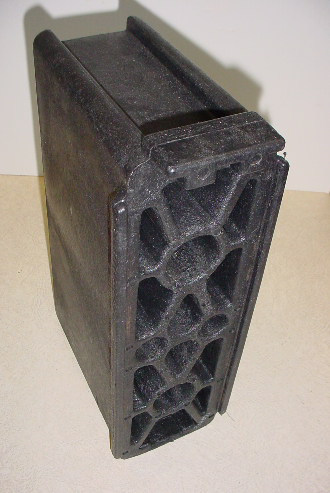
Alternate Guardrail Blockouts
SCD GR-2.1 and OMM Approved List |
| Besides the generic 6"x8" wood blockouts, there are various brands of recycled plastic, rubber, and even a privately developed generic narrow (4") wood blockouts for steel posts, rectangular and round wood posts. Typically, these alternate blockouts are only used on longitudinal guardrail runs. They are not to be used in transitions (BTAs) or as part of proprietary end treatments. |
|
 |
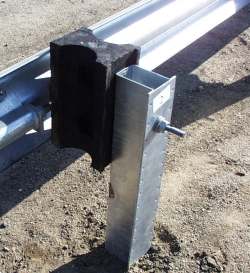
Alternate Guardrail Post
SCD GR-2.1 and OMM Approved List
X-44 Post, HALCO, LLC |
 |
|
ODOT specifies generic wood or steel posts as the standard. However, HALCO contracted with Battelle Memorial Institute to specifically engineer a steel post for w-beam guardrail installations. This steel post is strong, lightweight and designed to minimize the effects of wheel snagging. This post is considered "equivalent" with ODOT's generic wood and steel guardrail posts. The X-Post is shorter than the generic post so it can't be used if a longer post is needed for embedment, and for a few other situations. See the Office of Materials Management Approved List for more details.
|
Alternate Portable Barrier
SCD RM-4.2
J-J Hooks |
| The NJ Shape J-J Hooks is a proprietary "equivalent" to ODOT's generic NJ shape PCB. The J-J Hooks product is a proprietary barrier manufactured to Easi-Set's specifications. |
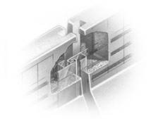 |
| J-J Hooks barrier meets NCHRP Report 350 TL-3 criteria if manufactured with a third rebar (sometime after April 1999). Any barrier (proprietary or generic) that is not Report 350 compliant is subject to a phase out period and is to be removed from service by January 1, 2008. ODOT required marking all compliant generic barrier with "350". Baxter Precast Products and Norwalk Concrete Industries stamped "350" on all complying J-J Hook barriers as well. It is not known how J-J Hooks barriers manufactured by out-of-state licensees identified compliant segments. Click to link to a FAQ page regarding the phase out period. This office is not willing to accept NCHRP 350 barriers from other states for use on ODOT projects. These other products have different shapes (F or NJ), cross section (widths), or connection types. One reason this is not permitted: those barrier segments would eventually become intermingled with ODOT's barrier and create potential snag points when an impacting vehicle travels from one segment to a dissimilar adjacent segment.
Although Portable Water-Filled Plastic Barriers are not a direct substitute for PCB, under certain conditions they are similar. They are discussed in the Specialty Products heading. |
Zoneguard Steel Traffic Barrier
Zoneguard barrier is an approved alternate to PCB. Addition product information is available at Hill and Smith, Inc.
Standard Installation Drawing
Minimum Deflection Drawing
Anchoring Drawing
|
Barrier Glare Screens
Traffic Engineering Plan Note 642-21 Traffic Engineering Manual and OMM Approved List
- various companies produce PCB glare screens. All products to have 18"- 24" green blades. Glare screens must be fastened to barriers according to the manufacturer's instructions. (TEM Plan Note does not contain all of the approved suppliers.)
Cable Median Barriers
High tensioned cable is a relatively new product in the United States, and installation of these products are still under review. Standards designs have not been released, but available products are:
- Brifen WRSF
- Nucor
- Trinity CASS
- SaFence
- Gibraltar |
Specialty Products There are a myriad of special roadside safety products available for the designer to use in hard to protect installations. The following products are not currently ODOT Standards as their use in Ohio may be limited, or not even used at all. All of the products listed here, however, are federally accepted as NCHRP Report 350 barriers. And as Report 350 products, the Roadway Standards section would accept their use on ODOT projects if deemed necessary by the designer, is the appropriate Test Level, and is acceptable by other affected ODOT offices - most notably Maintenance Administration, Roadway Engineering Services and Traffic Engineering.
Other federally accepted NCHRP Report 350 products (those not mentioned in this heading, or elsewhere on this web page) are not currently accepted for use on the state's highway system. If the designer desires to use such a product, however, contact the Standards Engineer as soon as soon as practical in the project's design phase.
Aesthetic Barriers
Communities often express their desire for "good looking" barriers. While ODOT acknowledges this desire, it is not in the position to advocate the use of them. For one thing, not all aesthetic barriers are considered as such by everyone, and worse, some aesthetic barriers have severe design limitations. And few such barriers are rated for high speed traffic and even fewer have crashworthy end terminals.
There are a variety of generic aesthetic guardrails and concrete systems are available, like the ones from FHWA's Western Federal Lands Highway Division. One example of a proprietary rail is Ironwood. On the Roadway Standards FAQ web page, ODOT issued a primer of pertinent aesthetic barrier information for semi-rigid and rigid longitudinal barriers.
ODOT and many local agencies cannot justify the additional cost of these barriers. For example, one suburban city in Central Ohio uses an "aesthetic" proprietary guardrail on its city street system that costs seven times as much as ODOT Type 5. ODOT may give permission to government entities to install aesthetic barriers on the State system, but at no additional cost to ODOT.
Additionally, maintenance is required to ensure these systems remain aesthetic over time. Usually ODOT is not in a position to maintain the system or stock the product's parts, so some sort of ODOT maintenance agreement may have to be negotiated with the advocating entity.
Many times, the issue the local jurisdiction has with guardrail is the color of the zinc galvanizing. The entities want to color the rail panels and other components with a "natural looking" green or brown color. However, be aware that a dark color, for example black, may not be sufficiently visible to the motorist at night and should be disallowed for safety reasons. And all barrier systems (aesthetic and standard) still need to utilize barrier reflectors as per CMS 626.
Cushion Wall
Energy Absorption, Inc, developed the Cushion Wall as a reusable longitudinal barrier made from a single row of cylinders that have the ability to recover a major portion of their shape, position, and capabilities after being impacted.
Movable Barrier
Quickchange Barrier, from Barrier Systems, Inc. uses a specially designed vehicle to move barrier runs upwards of 26 feet laterally, opening traffic lanes in a matter of minutes. It is a good product for reducing delays from lane closures in long duration work zones, and in permanent situations where there are high directional traffic volumes.
This movable barrier uses Barrier System's ABSORB 350 as its crashworthy end treatment. The ABSORB 350 system is a non-redirective, gating crash cushion that can be used with the Quickchange Barrier.
Portable Water-Filled Barriers
These lightweight, plastic barriers are usually used as a channelizing device and are subject to the rules of the Office of Traffic Engineering.
It seems as if most Portable Water-Filled Barriers (PWFB) products are also upgradeable to longitudinal barriers meeting the crash testing criteria of NCHRP Report 350 for Test Level 2 or 3 conditions. Rules for using PWFB as longitudinal barriers are under the auspices of the Office of Roadway Engineering and are summarized here.
Although PWFB do not have a standard use within ODOT, there may be project specific situations when they are desired in lieu of portable concrete barrier (PCB). Such situations may be in urban settings, or where its lighter weight or portability is desirable. When used as longitudinal barriers designers must ensure that PWFB function as a crashworthy barrier including addressing the significantly increased deflections over PCB. It is up to the designer to ensure plans detail (or for the Project Engineer the construction includes) the following:
- the appropriate Test Level (TL-2 up to 40 mph design speed, TL-3, 60 mph)
- sufficient deflection offset, (product and TL dependent)
- the product's specific "350 upgrade kit" (the steel framing, connection stiffeners, and/or pedestals which allows it to absorb and transfer impact energy),
- the required minimum number of interconnected units for that product (for developing longitudinal tension),
- each unit filled with water to the appropriate level specified by the manufacturer,
- terminals flared out of the clear zone, unless terminated with a crashworthy end treatment and
- a stipulation that the entire run consists of segments from the same manufacturer.
If these conditions are met, any of the PWFB products listed in FHWA's Roadside Hardware Acceptance Letters page (Keyword: Water-Filled Barriers) are allowed. ODOT does not maintain a list of approved PWFB products.
It is the discretion of the designer to specify PWFB instead of PCB. The contractor can not make this substitution, unless approved by the Project Engineer.
Railroad Crossing Barrier
The Stop Gate, from Energy Absorption, Inc. helps prevent vehicle intrusions. Unlike traditional warning gates, the Stop Gate creates a crashworthy, positive barrier that does not allow vehicles to pass around the lowered gate arm.
|