|
Link to FHWA's Safety FAQ for Barriers:
http://safety.fhwa.dot.gov/roadway_dept/policy_guide/road_hardware/qa_bttabr.cfm
The information on the page below pertains to responsibilities of the Roadway Standards Section within the Office of Roadway Engineering: Location & Design Manual, Volume 1, Roadway Standard Drawings, Traffic Barriers and End Terminals, Shoulder Rumble Strips, and Landscaping.
Accessible Public Rights-of-Way
Accessible Sidewalks
Aesthetic Urban Gateways
Anchoring of Guardrail
Barrier Protection in Low Speed, Low Volume, or Urban Environments
Bridge Guardrail Protection Involving Drives or Side Roads - L&D Figure 603-4
Bridge Terminal Assemblies, Upgrading to Standards
Bridge Terminal Assembly Type 1 - SCD GR-3.1
Concrete Barrier Reinforcement and Foundations
Concrete Barrier Shapes
Design Exceptions for Guardrails
Designing Sidewalks and Trails for Access
Encroachments on State Right of Way
End Terminal Grading
Energy Absorbing versus Gating End Terminals
Flaring Tangential End Treatments
Gore Protection
Grading Behind Curb - L&D Figure 307-6
Guardrail Height
Guardrail Nesting
Guardrail in Conjunction with Curbs - L&D Section 602.1.5
Guardrail Soils - L&D Section 603.1.1.1
Guardrail Splicing - Plan Note R111
Guardrail with Tubular Backup - SCD GR-2.2
Historical Publications
Length of Need Calculation Spreadsheet (for tangential alignments)
Light Poles behind Guardrail
Long Span Guardrail - SCD MGS-2.3
LPA Standards
NCHRP Report 350, Test Levels, and MASH
Pocket Guide on Roadside Safety
Portable Concrete Barrier - Anchoring in Asphalt Pavement
Portable Concrete Barrier - "Drop Dead" Date for Previous Designs
Portable Concrete Barrier - Lateral Deflection
Portable Concrete Barrier - Minimum Curve Radius
Portable Concrete Barrier - Use of Barrier from other States
Portable Concrete Barrier - 50 Inch Tall Barrier
Portable Water-Filled Barriers
Proprietary Roadside Safety Devices
Re-lapping of Guardrail in Work Zones
Right-of-Way Fencing Options for Communities
Rumble Strips vs. Stripes
Shoulder Width on Ramps - L&D Figure 303-1
Specifying Impact Attenuators in the Plans
Truck Lane Width, FAP or NHS - L&D Figure 301-4
Accessible Public Rights-of-Way 
The U.S. Access Board is the Federal Agency that regulates Accessible Design Standards, and more specifically the Public Rights-of-Way Access Advisory Committee (PROWAAC) has published their latest design requirements here.
Acessibility Guidelines for Pedestrian Facilities in the Public Right-of-Way
Accessible Sidewalks
The U. S. Access Board encourages designers and engineers to watch these short films showing some of the difficulties disabled persons may have while traveling as pedestrians. Each video clip highlights unique problems impeding certain groups of individuals while maneuvering across commonly found pedestrian components. Sometimes, specific design elements for one disabled group can lead to access issues for another group. Watching all four clips gives a much better overall perspective on accessibility.
Aesthetic Urban Gateways
Some municipalities would like to provide a visually pleasing entrance to their communities. These Gateway designs are usually located at interchanges or where a high-speed state route enters the urban area. ODOT's Landscaping Guidelines a section of the Location and Design Manual Volume 1, provides design requirements for aesthetic treatments on state Right-of-Way.
Landscaping Guidelines address the Roadside Safety aspect of roadside beautification in general terms to mitigate the undesirable results of an errant motorist. Designers and landscape architects are reminded that additional fixed objects and landscaping are in most cases considered hazards to the traveling public.
Some communities have expressed their desire for aesthetic barriers. Some aesthetic barriers have severe design limitations that limit their use on high speed roadways and lack of crashworthy end terminals.
ODOT and many local agencies cannot justify the additional cost of aesthetic barriers. For example, one suburban city in Central Ohio uses an "aesthetic" proprietary guardrail on its city street that costs seven times as much as ODOT's standard guardrail. ODOT may give permission to government entities to install aesthetic barriers on the ODOT system, but at no additional cost to ODOT.
Additionally, maintenance is required to ensure these systems remain aesthetic over time. Usually ODOT is not in a position to maintain these systems or stock repair parts, so a maintenance agreement should be negotiated before the project is sold.
Many times, the local jurisdiction does not like the color of the zinc galvanizing. The local agency wants to color the guardrail with a "natural looking" green or brown color. Be aware that a dark color, like black, is not sufficiently visible to motorists at night and should be disallowed for safety reasons. All barrier systems aesthetic and standard still need to utilize barrier reflectors as per CMS 626.
Anchoring of Guardrail
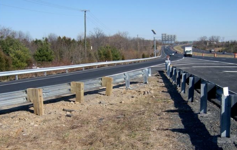
Longitudinal runs of guardrail need to be appropriate anchored. Guardrail works best if impact energy is allowed to be transferred both downstream and upstream through rail elements by utilizing the tensile capabilities of the w-beam material. 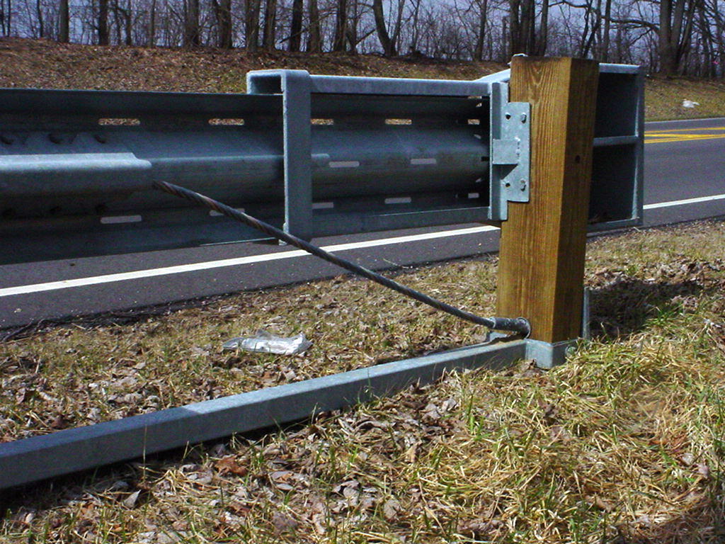 If a vehicle hits near the end of a run of guardrail, adequate tension at the end may not be developed. Anchoring is needed to prevent the guardrail end from "flailing" and allowing the vehicle to pass through the system within the LON. The photograph shows a cable assembly in a crashworthy anchor terminal. The cable is ready to provide tension to rail elements if a vechicle impacts the guardrail at the LON point for the end treatment(at post number 3). If a vehicle hits near the end of a run of guardrail, adequate tension at the end may not be developed. Anchoring is needed to prevent the guardrail end from "flailing" and allowing the vehicle to pass through the system within the LON. The photograph shows a cable assembly in a crashworthy anchor terminal. The cable is ready to provide tension to rail elements if a vechicle impacts the guardrail at the LON point for the end treatment(at post number 3).
Both the upstream and downstream ends of any guardrail run require anchoring with an appropriate anchor assembly. If the end treatment is located in the Clear Zone of any lanes of traffic, use a crashworthy end terminal. Appropriate devices are discussed in L&D Section 603.3.
Barrier Protection in Low Speed, Low Volume, or Urban Environments
Q. What options do designers have for the use of barriers in low speed situations? Is guardrail needed in urban areas?
A. The required Clear Zone is reduced for roadways with lower speeds and traffic volumes as mentioned in L&D Section 600.2.2. Section 601.1.4 suggests protection may not be required, under certain conditions, on city streets and urban type of facilities with design speed less than 50 mph. Section 601.1.5 states protection is discretionary on very low-volume local roads.
FHWA mandates barrier protection equal to NCHRP Report 350 or MASH TL-3 on the NHS and ODOT extends this requirement to the state system (Section 601.3). It is reasonable for designers to specify TL-2 in low speed urban areas if a TL-3 device won't fit, or due to some other factor.
Sometimes municipalities would rather use curbing instead of barrier protection. But curbs are never a substitute for guardrail (Section 602.1.5).
It is important however, that any installation of any barrier system on low speed (or volume) roadways be installed to the same criteria as used on high speed (or high volume) facilities (Section 602.1.5.2). As an example, do not reinstall a trailing end Type T anchor on the approach end of a guardrail run, just because the roadway is low speed. Ensure a crashworthy Type E or similar product is installed.
Bridge Guardrail Protection Involving Drives or Side Roads
Q. We are proposing to replace the existing guardrail transition at a structure with one of the standard Bridge Terminal Assemblies. Our dilemma is that we have a county road intersection just west of the structure where the center lines of the side roads are 50 feet from the end bridge railing. At what point on the BTA can we begin the radii?
A. A general answer is this: the more tangential guardrail available, the better. Anytime there is less then ideal tangential length at a bridge or a similar rigid barrier at intersections, the application of L&D Figure 603-4 is important. The best solution is to move the side road further to the west so there is sufficient distance to apply the Preferred Minimum Approach Treatment detail. Unless the scope of the project includes relocating the cross road, however, a designer can only work within the limits that are available. In that case install the short radius guardrail as per Absolute Minimum Approach Treatment. The radius can begin at the distance shown on the Figure 603-4E. Some transitions can be flared as well, check the appropriate standard drawing.
The problem with radius guardrail is that a vehicle striking the BTA may not be sufficiently contained by the radius, because of insufficient upstream anchoring. In an impact with unanchored or under anchored ends, the impact could cause the BTA to flail allowing the vehicle to gate through the system. While gating is bad enough on a normal LON guardrail run, at the end of a bridge rail it could cause severe pocketing. That's the reason for the tangent rail elements and anchoring on Figure 603-4.
Bridge Terminal Assemblies, Upgrading to Standards
FHWA's requirement to install roadside safety devices meeting NCHRP Report 350 TL-3 criteria on the NHS has prompted concern regarding the practicality of upgrading existing non-compliant BTA's on certain type of projects. Beside the standard SCD MGS-3.1 transition drawing, designers have additional Ohio approved 350 transitions available: BR-1 Transition, GR-3.3, and GR-3.4 published as a Roadway Plan Insert Sheet.
The designer should utilize one of the standard BTA's if possible. If a standard BTA is not compatible with the structure then reinstallation one of ODOT's former BTA is acceptable. These are the BTA Types C, D, E & F, and BTA Types G, H & J, loctated on the Archive SCD website.
Transitions are use to develop guardrail strength between the semi-rigid guardrail and the rigid bridge parapet. This is done to prevent a vehicle from pocketing or snagging the corner of the bridge rail. Transitions typically use a combination of larger posts, decreased post spacing, increased rail cross section(either by a thrie beam element or nesting rails). In Ohio a curb, if needed, is generally used to keep an impacting vehicle's wheel from catching on the posts. Designs from other states may have been developed independently and those states might have opted to use a rub rail instead of a curb. Unfortunately, a substitution of a rub rail in place of a curb on our design is not acceptable.
See the Bridge Terminal Assembly, Guardrail, and End Treatment IOC dated May 30, 2000 for project specific upgrade information. L&D Section 603.5 has more information on ODOT's standard designs.
And the 2013 OTEC Presentation on thei subject:  2013_OTEC BTA Presentation.pdf 2013_OTEC BTA Presentation.pdf
In no case should approach guardrail remain unconnected to a bridge rail.
Bridge Terminal Assembly Type 1
In 2001 FHWA contracted TTI to test a modified design of ODOT's Type 1 BTA to NCHRP Report 350 TL-4. TTI's Dr. Dean Alberson designed two modifications to make the BTA compliant, (1) a curb, and (2) a heavier gauge w-beam to thrie beam transition panel. Current crash testing criteria unavoidably moved the the snag point for the transition from rear of a BTA at the parapet to the front of the transition, so the use of a heavier panel mitigates that adverse effect. The addition of the curb helps to ensure the wheel of the impacting vehicle is not snagged on posts underneath the rail.
In 2012 A new transition was developed for the use with MGS guardrail. Testing showed that when curb was continued upstream of the transition, the standrad MGS tore away from the transtion point and the test vehicle was not safely redirected (a failure in crashworthiness). The solution was to strengthen the connection of the MGS rail to the transition by nesting an additional panel of w-beam upstream of the transtion (or a single heavier 10-gauge w-beam panel may be used). See SCD MGS-3.1.
To retrofit an existing Type 1 BTA construct a curb under the thrie beam rail element, if not present, and replace the 6'3" long w-beam to thrie beam transition section with a heavier 10 gauge panel. Refer to L&D Sections 603.5.1 and 603.5.2 for these BTA types.
In certain situations a design using a prefabricated steel curb assembly may be used to retrofit Type 1 BTA to current crashworthy standards detailed as a Plan Insert Sheet.
Concrete Barrier Reinforcement and Foundations
ODOT changed its barrier design from NJ Shape Concrete Barrier to the Single Slope in 2003. Single slope barrier does not have rebar in it except for in the 15 ft. long end anchorages which are required at the ends of barrier runs and at expansion joints.
The single slope standard does not require a concete base outside the aforementioned end sections as was required with the previous NJ safety shape. The single slope barrier, however, does need a solid base material (asphalt or aggregate) to support its own weight, and an overlay of material at the toe of the barrier.
Concrete Barrier Shapes
The change in the vehicle fleet over the years has reduced the effectiveness of standard barrier shapes. The original GM shape barrier has been out of favor for many years, and although the NJ shape is still valid, its days are probably numbered. Remaining acceptable cross sections include the F shape and the Single Slope. The Single Slope Barrier is the current ODOT standard as described in L&D Section 603.1.2 and SCD RM-4.3 through RM-4.6. The transition from NJ Shape Concrete Barrier to the Single Slope is available as a Plan Insert Sheet.
Design Exceptions for Guardrails
There are none. Although not always possible, guardrail, other longitudinal barriers, end treatments, anchor assemblies and impact attenuators should be designed according to standards. Barrier offset should meet lateral clearance design exception criteria as shown in L&D Section 100. Lateral clearance is considered a Geometric parameter, not a barrier standard.
Designing Sidewalks, Trails and Shared Use Paths for Accessibility
Complying with ADA standards in public rights-of-ways can be difficult. Sidewalks, street crossings, and other elements of the outdoor environment present unique challenges to accessibility for which specific guidance is considered essential. Refer to L&D Volume 1 Section 306 and Standard Construction Drawing BP-7.1 for information on Sidewalks and Curb Ramps.
Encroachemnts within the Right of Way
Privately owned roadside hazards (encroachments) within the Right of Way shall not be closer than the offsets described in to L&D Volume 1 Section 602. Click for: Summary/Example.
End Terminal Grading
Grading in the area of the terminal is an important consideration. Terminals are tested for crashworthiness on flat and unobstructed terrain, features seldom found in the field. Advance, adjacent and run-out distance grading should be considered, so that impacting vehicles can reasonably be expected to engage the end terminal safely at different stages of the impact.
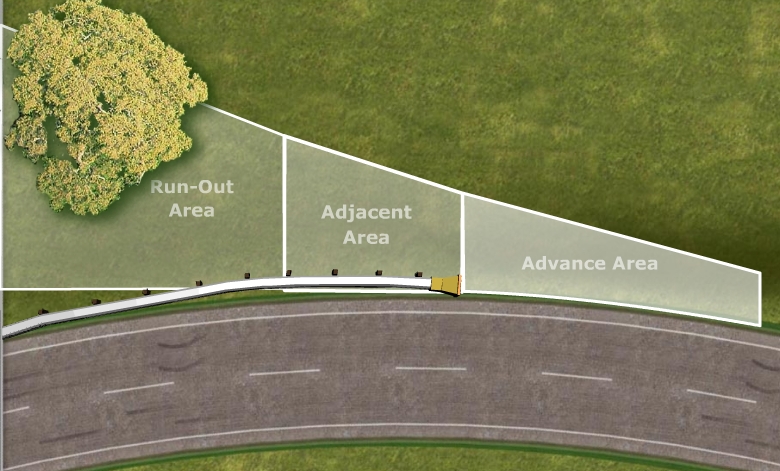
Advance grading is the area in which the vehicle traverses prior to impacting the end terminal, and for w-beam terminal should be no more than 10:1 to ensure the vehicle is stable at the moment of impact. Adjacent grading is an area along side and immediately behind the end so that a vehicle will still be level and not have had a chance to roll while initially engaging the end terminal. Run-out distance grading is the area a vehicle may travel after contacting the terminal. This area can be considerable, but FHWA recommends a minimum of 20 feet laterally and 75 longitudinally behind the terminal end if practical to obtain. There are many locations where this is not practical, because of physical constraints such a restricted rights-of-way, environmental concerns, or other issues. See L&D Section 602.1.4.
Energy Absorbing versus Non-Energy Absorbing End Terminals
Guardrail End Terminals protect the blunt end of a guardrail run by either absorbing energy or gating in an impact. Some terminals do both methods depending on the impact. A gating terminal allows an impacting vehicle to safely "pass through" the end of the terminal. However, the speed of the vehicle is only minimally reduced, and even in successful crash tests vehicles have continued over 150 feet behind and parallel to the terminal - see photograph and inset showing extent of run out in a successful gating impact.
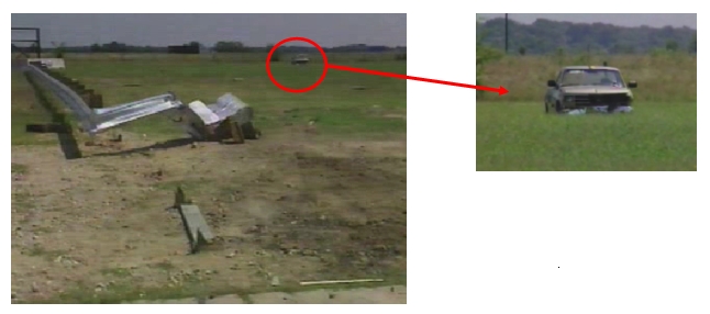
| Conversely, energy absorbing terminals like the ET-2000, SKT and the FLEAT are designed to safely decelerate a vehicle's occupants in as little as 50 feet, if hit end-on. |
|
The decision to use an energy absorbing terminal versus a non-energy absorbing one should be based on the likelihood of a near end-on impact and the nature of the recovery area immediately behind and beyond the terminal. If a barrier length of need is properly determined, it is unlikely that a vehicle will reach the primary shield object after an end-on impact regardless of the terminal type selected. However, if the terrain beyond the terminal end and immediately behind the barrier is not safely traversable, an energy absorbing terminal is recommended.
For angle hits of 15 degrees or higher at the first post, all w-beam terminals perform about the same. Impacting vehicles will travel behind and beyond the terminal until they are stopped safely. stopped abruptly, or roll over.
Flaring Tangential End Treatments
Q. Can a Type E guardrail end treatment be flared, such as when installed in a tight radiused ramp?
A. In frontal hits, the energy absorbing end treatments like the ET-Plus, SKT and even the Type B's FLEAT, performs best when the impact head acts on a rigid w-beam "column". So the unit should not be radiused or curved, especially in the first 50 feet.
Gore Protection
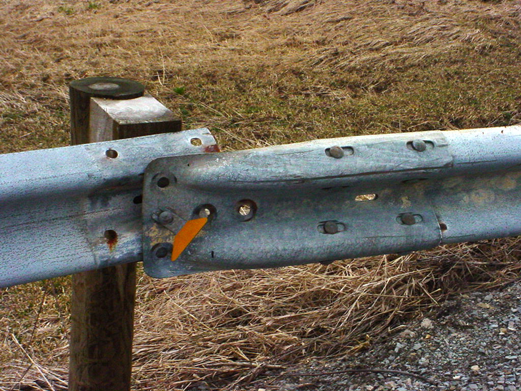
Designers are asked to close short gaps between two runs of guardrail in L&D Section 602.1.2. Likewise, the use of two separated runs of guardrail at a gore should be avoided. Such situations would be as shown here, where (because of some unseen fixed object behind the camera) a run of guardrail is on the left side of the ramp and also the right side of the mainline. Although each guardrail run is terminated by a Type E anchor, a better solution would be to close off the opening by the installation of an impact attenuator (Section 603.4).
| A variation of this issue has occurred in which an impact attenuator has been installed at such a location, but the two runs of guardrail were not connected to the attenuator even though the guardrail runs were anchored(see picture below). The unconnected Type T guardrail anchor is clearly shown in the picture on the left. One of the problems here would be that the 12 foot Type T is not considered part of the LON (Section 603.3.5), so a vehicle impacting either side of the Type 2 impact attenuator could possibly be redirected into the non-LON portion of the Type T's and then "gate" through to the fixed object. It is recommended that designers "close the gap" here as well, by specifying the attenuator manufacturer's w-beam transition. |
 |
 |
Grading Behind Curb
Q. Regarding grading behind curbed streets (L&D Figure 307-6), how wide does the 4%-8% grade need to be? The figure shows it to the R/W line without sidewalk. In our situation, the R/W is extremely wide and there's no sidewalk. We need a minimum width of 4' for lighting at 4%-8%. After that, I'd like to know if we can then break the shoulder over? The area behind the break-over would still be within the clear zone, so we would still use appropriate grades behind the break-over. The benefit here is to minimize the drainage going into the closed roadway storm sewer and utilize the nearby ditch drainage system as much as possible.
A. The 4% to 8% slopes on Figure 307-6 were extended to the R/W line to prevent runoff from the right-of-way entering private property. If you can maintain the highway runoff on the highway right-of-way, then we see no reason you cannot break the slope closer to the curb as long as flat slopes are maintained within the clear zone. A note has been added to the figure (1/21/07) to reflect this.
Guardrail Height
The height of guardrail is determined from years of crash testing. Crash testing has shown the height is important for the proper performance of the guardrail in vehicle impacts. An installation too low may allow a larger vehicle with a relatively high center of gravity to climb the barrier, while too high of an installation may let a smaller vehicle slip underneath. In Ohio, guardrail height is measured as shown on SCD MGS-1.1 for various configurations.
Guardrail in Conjunction with Curbs
Curbs are an important hydraulic feature along roadways, but may affect the severity of an accident when guardrail is present. Vehicles impacting guardrail can have negative consequences if a curb has influenced the vehicle's trajectory by compressing (or extending) the vehicle's suspension system. At certain impacting speeds and angles, curbs can even "trip" a vehicle causing the vehicle to roll. Curbs are not generally recommended on high speed roadways, but are desired in some situations. On either low speed or high speed facilities, designers should follow L&D Section and 602.1.5 for curb use and guardrail placement.
Guardrail Soils
Q. A city has decided to upgrade its guardrail standards due to a severe crash. One particular run of guardrail is in a floodplain and the city's consultant questions if the native soil there is appropriate for guardrail posts, or if the posts should be reset with some type of gradated backfill material. L&D Section 603.1.1.1 states that adequate soil support must be provided for the posts in a guardrail run for the guardrail system to perform properly during an impact. What is "adequate" soil?
A. Almost all soils found in Ohio are adequate to provide sufficient lateral resistance to absorb energy for guardrail posts in a crash. For impact performance, too much resistance can be detrimental. AASHTO defines a "Strong Soil" for crash testing purposes, which Dr. John Rhode of the Midwest Roadside Safety Facility says simulates the worst case scenario. It is appropriate to install guardrail posts in native soils, as in general this provides superior performance to soils utilized in crash testing.
There are a couple of other guardrail post installation items worthy of mention here:
- Concrete encasement of posts is not allowed except for those specific situations mentioned on the Standard Drawings.
- If vegetation control is desired and asphalt paving is the method chosen, refer to Plan Note R116 - Paving Under Guardrail in Appendix B of the L&D Manual, Volume 1. An alternate method is the Texas Mow Strip. Details are available from the Standards Engineer.
Guardrail Splicing
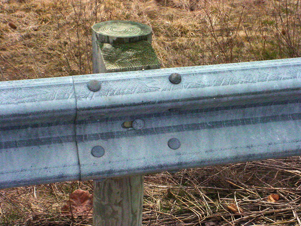
W-beam guardrail is designed to absorb impact energy by transferring tensile force stresses within the rail sections to adjacent rail elements. Strong connections between guardrail panels is needed to safely contain an impacting vehicle. It has been calculated that this impact energy can be transferred 150 to 300 feet longitudinally in a guardrail run. If guardrail panels are not properly connected the impact forces can not be transferred most likely causing the rail to rupture.
 |
 |
Eight splice bolts required |
Not Acceptable |
Guardrail panels should always be spliced correctly, ideally by using only full guardrail panels using the eight factory fabricated splice bolt holes at each end. If for some reason a shorter rail element is needed to connect two panels(such as connecting a new guardrail run with existing guardrail) both sections should be overlapped and have eight splice bolts. This method of fastening is the only approved method and is covered in AASHTO Specification M-180(Figure 1, Beam Splice detail). For this reason Plan Note R111 - Connection Between Existing and Proposed Guardrail located in Appendix B of the L&D Manual, Volume 1 should be included in the plans.
Guardrail with Tubular Backup
The Type 5 guardrail with Tubular Backup, SCD GR-2.2, meets all criteria for TL-3 and can be used on the NHS. Computer simulation confirmed the new system is capable of handling TL-3 impacts when used in conjunction with the Type 4 Bridge Terminal Assembly as shown on SCD GR-3.4. For retrofit applications, the only difference between the restricted previous design and the TL-3 one published in January 2006 is the addition of a second (nested) w-beam rail element across the length of the backup. One of the unique problems Dr. Plaxico found was that the transition for this system could, in certain mounting situations, be more rigid than the tubular backup.
Historical Publications
Office of Roadway Engineering maintains rescinded Roadway Standard Construction Drawings (BP, F, GR RM and LA series) and previous versions of L&D Manual, Volume 1. Most Standard drawings starting in the 1930's, and Design Manuals from the mid-1950's, are archived.
For the historical editions of the following selected publications contact the indicated office:
Problems Encountered by Generically Specifying Proprietary Products
Another consideration the designer must make is whether design conditions or available space for the impact attenuator will accept all of the approved products. There are two likely scenarios for this to happen. In both cases, proper detailing of the design speed, hazard width and available footprint for the Type 2 (or Type 3) is sufficient to place the selection burden on the contractor, without the designer having to take the time to differentiate between the various products.
- Product Availability One place this would happen is at the edges of the product envelope where one vendor may not have an available product, such as for high speeds (70 mph) or very wide hazard protection (120 inches). As long as the design speed and hazard widths are labeled on the plans for each occurrence of an impact attenuator, it is up to the contractor to bid an appropriately sized product. Vendors are filling the gaps in each product line to be competitive, but there probably always will be product outliers.
- Product Footprint The most likely example may be the length of the impact attenuator needed to develop the required width for hazards over 60 inches wide. As an example, the QuadGuard and the TAU develop units of different widths by flaring the sides at different rates over a standard length, while the TRACC develops its width by adding wing extensions to the end of a standard product. For example, to protect a 90 inch wide hazard for 60 mph, the QuadGuard model QS9006Y (6-bay) would need 22'1", the 90 inch & 60 mph TAU (7-bay) would be approximately 24'7". The standard 58 inch wide 60 mph WideTRACC needs the unit's 21'3" double flared length and an additional 32 inches of width. On the TRACC an additional 28 inch panel extension (or bay) adds an additional 6-7/8" of width. In this example an additional five 28 inch extensions would add 34-3/8" of width, for a total system length of 32'11".
Thus, the length of the impact attenuator footprint in this example could be from 22'1" to 32'11". Under some geometric design conditions, the space may not be available for a longer unit While the chances of this scenario occurring is somewhat minimal, a change order would be required to be executed to correct the situation. The designer should clearly specify the limits (footprint) available for the impact attenuator on the plans, so bidding contractors will have to determine if the unit they want to bid will fit. Or the designer may choose to revise the plan note to limit the approved devices to those which will fit.
Each product has a variety of drawings covering different widths, types of backups, transitions options, etc.
Length of Need Calculation Spreadsheet
Spreadsheet for tangential alignemts (separate tabs for Type 5, MGS, and Concrete Barrier) for both adjacent and opposing traffic:
length of need.xls
Light Poles behind Guardrail
Research by Battelle's Dr. James Kennedy for ODOT in 1995 showed that Type 5strong post guardrail installed in front of cantilevered breakaway light poles on "A" or "X" bases do not inhibit the function of the guardrail as it deflects in an impact.
Long Span Guardrail
Q. SCD MGS-2.3 shows that the Long Span Guardrail deflects up to 8 feet. If hazards should be outside of the deflection area, shouldn't the headwall also be placed back this distance?
A. The crash testing of the long-span MGS guardrail system was conducted with a culvert headwall lined up with the back of the posts. Upon an impact at 62 mph and a 25 degree impact angle, a pickup truck was safely redirected without sinking down into the void behind the headwall. However, above grade hazards should still not be placed within this deflection area. So, for example, you would not allow a utility pole adjacent to the culvert area within 8 feet of the guardrail.
Also important with the Long Span design is including 62.5 ft of standard MGS rail beyond the speacial breakaway CRT posts in order to maintain strength and tension in the overall system. L&D Section 603.1.1.5 has a brief description of long span designs.
LPA Standards
Q. A Local Public Agency (LPA) has come up with a guardrail design for a bridge terminal assembly and an anchor assembly. Since this is for an LPA job, and the local has published standards, is their design OK? I am sure this hasn't been crash tested. What kind of flexibility do the Districts have in approving local standards?
A. The administration of LPA projects are covered in ODOT's Policy 25-001(P). This policy states in the 3rd paragraph that "...LPAs may design and develop projects in accordance with existing local design standards adopted by the LPA. Such standards and requirements shall be in accordance with generally accepted engineering safety, design and construction standards...."
As such ODOT does not have approval authority. However, this LPA design would most likely not meet current crash testing standards. It is encouraged for the LPA to use ODOT's standard designs, or to independently crash test their design to ensure its safety and effectiveness.
NCHRP Report 350, Test Levels, and MASH
This 1993 National Cooperative Highway Research Report on "Recommended Procedures for the Safety Performance Evaluation of Highway Features" details the methodology for testing roadside safety products for crashworthiness. It replaced NCHRP Report 230, the previous standard.
Six Test Levels are defined, with Test Level 3 being the most important for the majority of devices. Depending on the product to be tested three to seven crash tests are required, but some of these tests may be waived if the results are not likely to provide new data over that observed in previous crash tests.
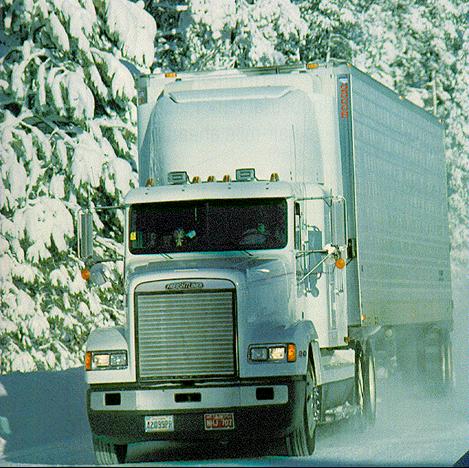
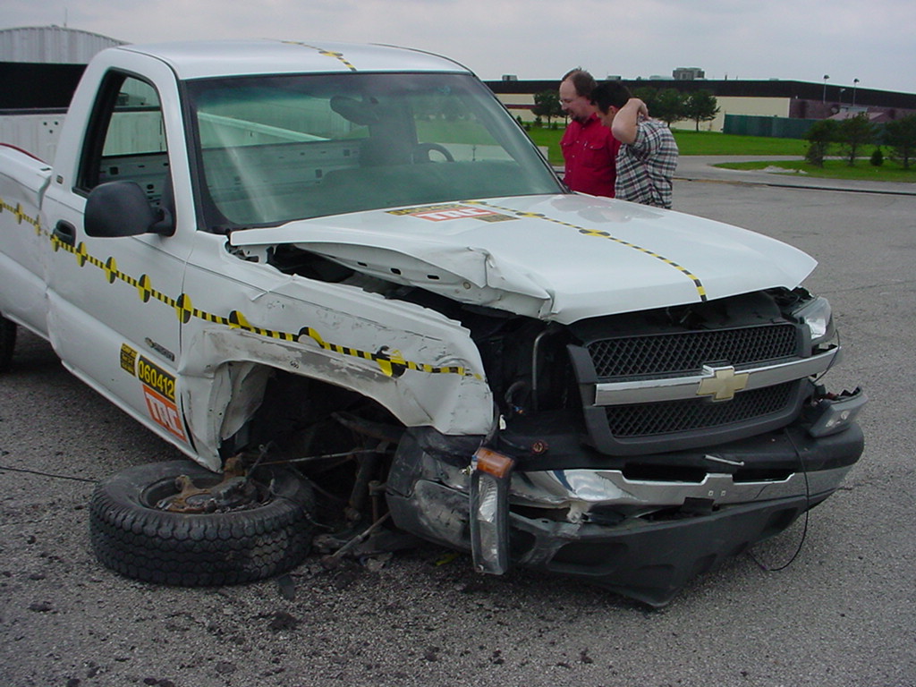
TL-3 is meant to be representative of the passenger car fleet, in that a light vehicle (similar to a Ford Focus or Geo Metro) is considered the basis for determining vehicle occupant survivability, and a heavier 3/4 ton pickup truck (i.e. Chevy C2500 or Ford F-250) is used to test the longitudinal barrier, or terminal's, structural capability. Test articles are impacted with these passenger vehicles at 100 km/hr (62.1 mph). TL-2 tests are conducted at 70 km/hr (43.5 mph), and 50 km/hr (31 mph) for TL-1.
Researchers are making great strides in product design by using finite element simulation, but for now actual crash tests are still required to validate those results. Each live test (see "Recipe for a crash test") can cost up from $35,000 to $50,000 for the required late model vehicle, test article installation, testing facility equipment and the final report.
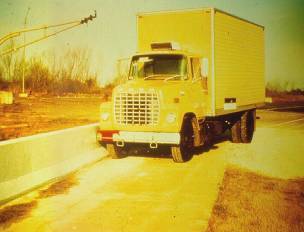
| Trucks of various sizes are tested at the higher test levels (TL-4 delivery truck, TL-5 tractor trailer, and TL-6 tanker truck) at 80 km/hr (49.7 mph). TL-4 though 6 determine the barrier's ability to contain the impacting truck. |
 |
 |
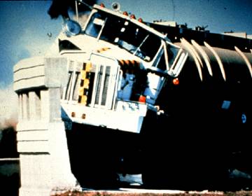 |
TL-4 Delivery |
TL-5 Tractor Trailer |
TL-6 Tanker |
| |
|
|
At least one concrete barrier design is rated to TL-6 (shown at right), but a vast majority of products are developed for TL-3, with a lesser number of TL-2 products available.
Products rated to TL-3 are considered to be appropriate for TL-2 and TL-1 locations. |
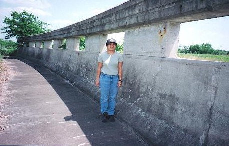 |
Texas DOT 90 inch TL-6 "Tall Wall" |
TL-3 is important in that FHWA requires all roadside safety devices used on the NHS to at least meet this level. ODOT extends this requirement to the state system, (L&D Section 601.3) except that it is reasonable for designers to specify TL-2 in low speed urban areas if a TL-3 device won't fit, or due to some other factor.
Some states define 45 mph as the limit for TL-2. But since roadside safety products are often energy absorbing devices, Ohio chooses to be conservative and rounds the TL-2 upper limit (43.5 mph) down to 40. Note that the TL-2 design limit is NOT the same as AASHTO's Green Book's definition of low speed/high speed. The Green Book defines low speed facilities as those with a design speed of less than 50.
Report 350 is currently being revised and is to be called MASH (Manual for Assessing Safity Hardware). FHWA has prepared a PowerPoint presentation titled Update of the US Crash Test Procedures covering completed NCHRP Research Project 22-14. A second project, the actual rewrite of Report 350 was expected to be completed in 2006, but it is still in final review by the panel members. See the Project 22-14 (02) link for an explanation.
Pocket Guide for Roadside Safety
PDF of the Guidelines for the Installation and Maintenance of Roadside Safety Hardware: Pocket Guide.
Portable Concrete Barrier - Anchoring in Asphalt Pavement
The information contained in ODOT's Office of Structural Engineering's PCB Design Data sheet and its PCB-91 Standard Drawing is intended for anchoring on concrete decks. ODOT has never issued guidance for other types of anchorage.
In 1999 Caltrans successfully crash tested to NCHRP Report 350 TL-3 its NJ shape barrier for use in semi-permanent location (5-years or more). This report, FHWA/CA/OR-99/07 is the basis for the following recommendation.
For a particular project, if the figures (graphs) on PCBDD indicate the barrier chain needs to be anchored, or barrier segments need to be anchored for other reasons, and anchoring cannot be done as per SCD PCB-91 because of the pavement material, then:
1) Use the PCB as detailed on PCB-91 (NJ shape segments with anchoring holes)
2) Anchor the PCB on at least 2 inches of asphalt with 4 anchoring bolts per barrier
segment, one located at each corner of the PCB. (Ignore the recommended number of
anchoring bolts given in Figure 3 of PCBDD.)
3) Each anchoring bolt shall be 1 inch diameter high-strength steel with a nut and washer as
specified in PCB-91.
4) Anchoring bolts will be a minimum of 36 inches long.
Portable Concrete Barrier - "Drop Dead" Date for Previous Designs
PCB which has not been casted to NCHRP Report 350 standards is no longer acceptable. Barriers in this category are those manufactured under former SCD RM-4.1M for the 50 inch, and RM-4.2M for the 32 inch. Those generic barriers were obsolete as of January 1, 2008. Any generic 32 inch PCB produced to SCD RM-4.2 after 1/18/02 is an approved design and remains usable.
ODOT redesigned the barrier depicted on SCD RM-4.1M from 1997 to be NCHRP 350 complaint. This was accomplished by the addition of an internal rebar cage. This reinforced barrier was successfully crash tested in October 2001 and the revised, reinforced, design was released as a standard drawing on 1/18/02. With the release of the 2002 drawing, ODOT required stamping of all compliant generic barrier with "350" marked on its top as per the standard drawing.
An alternate 32 inch barrier, the proprietary J-J Hooks PCB, is approved as an alternate to ODOT's generic one. J-J Hooks barrier meets NCHRP Report 350 TL-3 criteria if manufactured with a third rebar as per FHWA Acceptance Letter B-52, dated March 26, 1999. This deadline concurs with ODOT's Office of Construction's latest direction on the phase out of unmarked J-J Hooks barrier (segments not having "350" marked on them).
ODOT's 32 inch Bridge Mounted Barrier produced to Bridge Drawing PCB-91 is also 350 compliant, if the barrier has "350" stamped on it, or has the year 1993 (or later) "permanently impressed" on it as per the standard drawing. Since it is sometimes used in unanchored roadside applications, these bridge barrier segments are also exempted from the deadline when installed in freestanding runs.
ODOT's old 50 inch barrier design is also obsolete; however, the 2006 release of RM-4.1, (10/20/06) is adequately reinforced and is not affected by the phase out.
Portable Concrete Barrier - Lateral Deflection
Historically, ODOT has used 2 feet as the deflection of unanchored PCB. This dimension more realistically represents the desirable minimum offset distance from a traveled lane to the PCB.
With regards to probable deflections, most crash tested portable concrete barriers (nominal 60 mph, 25 degree with a 3/4 ton pickup truck) were displaced laterally up to between 5 to 6 feet. ODOT's own 32" design deflected 5.5 feet, but this 2001 crash test was conducted on a 244 feet long run unanchored at each end (Similarly, ODOT's generic 50" design deflected 6.2 feet in the 2006 compliance crash testing). It may be assumed that a longer run would have less deflection as more friction and tension would be available, and that impact angles in tight work zone locations are not as severe the 25 degree impact of the standard 3-11 test.
In 2003 the Midwest Roadside Safety Facility concluded in its "Deflection Limits for Temporary Concrete Barriers" report that the 85 percentile accident in a normal work zone installation would produce a 2 foot deflection in an Iowa barrier. It is assumed the differences between the Iowa and Ohio barriers would not be significant with respect to this report.
The report also says to use the full deflection if used in freestanding mode adjacent to the edge of a bridge deck or similar drop off - but ODOT designers should use Structural Engineering's Design Data Sheet PCBDD to calculate Bridge Mounted Barrier anchorage in these situations.
Two feet continues to be an appropriate deflection limit criterion between two sets of travel lanes. It is also a valid distance between PCB protecting the traveled lanes and construction equipment or personnel. But keep in mind that larger deflections are entirely possible. The full deflection offset is desirable if the barrier is protecting motorists from fixed objects.
Portable Concrete Barrier - Minimum Curve Radius
Q. What is the minimum curve radius for portable barrier?
A. The Office of Production simulated barrier movement by use of 3D models. The results for maximum horizontal deflection, along with crest and sag vertical curves are shown for both the ODOT 32" PCB (SCD RM-4.2) and 50" (SCD RM-4.1).
The J-J Hooks barrier, a proprietary alternate to ODOT's generic PCB, has a minimum horizontal radius that is calculated to be 100 feet. On vertical curves, the J-J is supposedly able to fit on a 100 foot sag, or a 175 foot crest curve.
Portable Concrete Barrier - Use of Barrier from other States
This office periodically receives requests from contractors to use NCHRP Report 350 compliant PCB on ODOT projects that is fabricated using another state DOT design. While the goal of any barrier run is to be Report 350 compliant, this office believes the designs from other states, if introduced into ODOT's barrier supply, could potentially create unnecessary safety issues.
Depending on the state, their barrier design could have a different shape, cross section width, or connecting hardware from that used in Ohio. It is believed that ensuring compatible barrier segments are ALWAYS together in a longitudinal run would become a logistical and inspection nightmare. Maybe this mixing of inappropriate segments would not happen on the first project the other barrier is used, but during subsequent projects, these barrier segments would undoubtedly become intermixed with ODOT barrier.
Therefore, it is this office's position to not allow PCB from out-of-state.
Portable Concrete Barrier - 50 Inch Tall Barrier
Designers desire to specify a 50 inch tall portable concrete barrier to block headlight glare.
ODOT's previous 50 inch PCB was thought to have insufficient connection strength to meet crash testing requirements and was rescinded as a standard. As an alternate designers may place Traffic Engineering's Plan Note 642-21 in the project plans which allows the use of the new 32 inch PCB with plastic glare screen in lieu of the 50 inch PCB.
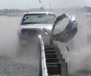
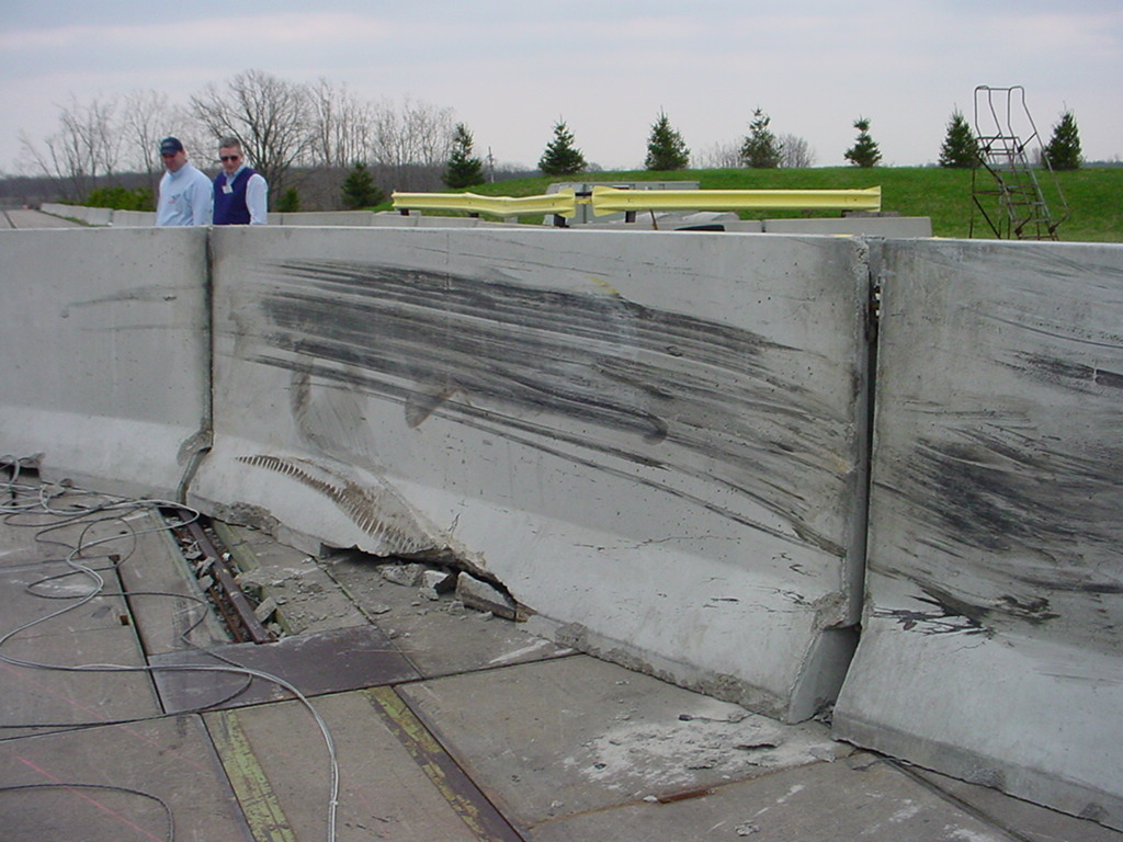
ODOT contracted with Battelle to develop a new design for the tall barrier, and that design was crash tested in April 2006 at TRC. Analysis of the crash data from high speed photography and accelerometers indicated the performance met NCHRP Report 350 3-11 requirements.
|
|
Barrier damage |
Vehicle damage |
FHWA acknowledged the barrier in its B-149 Acceptance Letter. This design is now published as SCD RM-4.1.
Portable Water-Filled Barriers
Q. A contractor has asked to substitute a vendor's plastic water-filled barrier in a location where PCB is specified. Can this substitution be made?
A. It's not likely. Traffic Engineering's MT drawings are designed specifically for the temporary concrete barriers and do not take into account the significantly larger deflection of the plastic barriers or of their lack of crashworthy end treatments. So it is imperative for designers to incorporate the limitations of this product into the project design early on, and a last minute substitution could end up creating a hazardous situation.
While it may seem as if most Portable Water-Filled Barriers (PWFB) products are also upgradeable to longitudinal barriers meeting the crash testing criteria of NCHRP Report 350 for Test Level 2 or 3 conditions, rules for using PWFB as longitudinal barriers are under the auspices of the Office of Roadway Engineering and are summarized here.
When used as longitudinal barriers designers must ensure that PWFB function as a crashworthy barrier including addressing the significantly increased deflections over PCB. It is up to the designer to ensure plans detail the following:
- the appropriate Test Level (TL-2 up to 40 mph design speed, TL-3, above 40 mph)
- sufficient deflection offset, (product and TL dependent)
- the product's specific "350 upgrade kit" (the steel framing, connection stiffeners, and/or pedestals which allows it to absorb and transfer impact energy),
- the required minimum number of interconnected units for that product (for developing longitudinal tension),
- each unit filled with water to the appropriate level specified by the manufacturer,
- terminals flared out of the clear zone, unless terminated with a crashworthy end treatment and
- a stipulation that the entire run consists of segments from the same manufacturer.
If these conditions are met, any of the PWFB products listed in FHWA's Roadside Hardware Acceptance Letters page (Keyword: Water-Filled Barriers) are allowed. ODOT does not maintain a list of approved PWFB products.
It is the discretion of the designer to specify PWFB instead of PCB. The contractor may not make this substitution. Proprietary Roadside Safety Devices
NCHRP Report 350 or MASH compliant End Terminals, Impact Attenuators and other specialty products are now most often developed and marketed by private manufacturers. A good starting point for the designer to determine which product is the best for a particular location is found on this office's Roadside Safety Devices web page.
Re-lapping of Guardrail in Work Zones
Q. Are contactors required to re-lap existing guardrail to the direction of traffic in crossover areas? Re-lapping could involve removing and re-lapping guardrail for several miles at a time. During the re-lapping process there will be a period of time when the guardrail will not be in place. It is felt that the benefit of the re-lapping is not worth all that is involved to re-lap it. Besides, this situation is present constantly on our 2-lane highways system on the left side of the center line.
A. The ODOT does not require re-lapping of guardrail when traffic is relocated across the median. In permanent applications, guardrail should be lapped in the direction of traffic. Crash testing has shown that incorrectly lapped w-beam rail elements (even though they are 0.1 inch thick) can cause a vehicle to snag and decelerate abruptly. Incorrect lapping on a short duration project is not as bad as other guardrail related problems. Other problems which present bigger issues would be ensuring crashworthy end terminals, correct end terminal grading, appropriate guardrail height, and proper transitions to bridge rail or concrete barrier. As long as the incorrect lapping is a temporary situation, it is agreed that re-lapping for MOT is not cost effective.
Right-of-Way Fencing Options for Communities
Many communities and adjacent land owners ask to remove ODOT's Right-of Way fencing, or provide an aesthetic R/W fence. ODOT understands this desire but will not pay the extra cost to remove the standard woven-wire fabric or chain link fencing to replace with decorative fence.
R/W fence is required as per L&D Section 606.1. Communities wishing to enhance ODOT R/W fencing and are willing to pay for the installation (and potential removal of existing fence) need to develop a systematic fencing scheme for use in the entire corridor. The R/W fencing scheme, material specifications, and detail drawings need to be approved by the Office of Roadway Engineering (ORE) prior to obtaining a permit. The permit to build and maintain the fence shall be submitted to the appropriate ODOT District office who will coordinate with ORE. A corridor R/W fencing scheme presents visual uniformity to the traveling public. Individual adjacent land owners will not be allowed to install their own design along their frontage within the state R/W.
Right-of-Way fence design must be "forgiving" to an errant motorist. Be advised that the top rail of a chain link fence has been removed from ODOT standards because of the capability of it to penetrate windshields when impacted by an errant vehicle. Any fence design should be designed with a minimal amount of materials. Note that horizontal top rails and masonry pilars are not allowed.
Community R/W fences are to be maintained by the community after first having obtained a maintenance permit. Any decorative fence falling into disrepair will be restored back to the ODOT standard fence at the community's expense.
Rumble Strips vs. Stripes
-Rumble Strips used in the shoulder on rural freeways are controlled by the Office of Roadway Engineering and are detailed in SCD BP-9.1 and discussed in L&D Section 605.
-Rumble STRIPES located underneath the pavement marking paint are controlled by the Office of Traffic Engineering PIS 206410, Rumble Stripes
-Contact the Office of Traffic Engineering and the TEM 1415-2.1 for information regarding Transverse rumble strips accross the entire lane.
Shoulder Width on Ramps
Q. There is some discussion on the true definition of “multi-lane” versus “single lane” ramps. Is the ramp definition based on the number of ramp lanes only at the gore and that definition holds throughout the length of the ramp? Or does the definition change at various points along the ramp as the number of lanes change? The confusion occurs when turn lanes are added to a single lane exit ramp as it starts out with 1-lane, but ends with 2+ lanes.
Specifically, do the single lane shoulder widths (3’ and 6’) remain throughout the entire length of the ramp regardless of whether the ramp becomes 2 or 3 lanes wide because of turn lanes? Or does the addition of turn lanes switch the shoulder widths to 4’ and 10’ per L&D Figure 303-1 for multi-lane ramps?
A. The addition of turn lanes does not make a single-lane ramp into a multi-lane ramp and the single-lane ramp shoulder widths should be used throughout the length of the ramp. Whether a ramp is single-lane or multi-lane is determined by the number of lanes at the ramp terminal not by how many turn-lanes or receiving lanes it may have at its intersection with the crossroad.
Specifying Impact Attenuators in the Plans
Vendors are asking for more information from designers when crash cushions are specified on the plans. These impact attenuators are bid for as a complete unit, but the contractors will need to know what ancillary items they should include in their bid to make the unit complete. For each occurrence for a Type 2 or Type 3 impact attenuator, the designer will detail design speed, hazard width, space available for the device, foundation material, and test level are all important for the bidder to prepare a knowledgeable bid.
Truck Lane Width, FAP or NHS
Note B of L&D Figure 301-4 states in part "...on all Federal Aid Primary (FAP) roadways at least one 12 foot lane in each direction is required. FAP listings may be obtained from Office of Technical Service's Roadway Inventory reports." A question on this note has been that since there is no longer a Federal Aid Primary system, as it was done away with in the mid 1990s, should the reference be made to the NHS instead?
No, the FAP is still valid as it was the way the lane width mandate was written. The 12 foot lanes was specifically mentioned as having to be on the FAP. In 23 CFR, Part 658, Appendix A (National Network), the following is stated for Ohio: "No additional routes have been federally designated; STAA-dimensioned commercial vehicles may legally operate on all Federal-aid Primary highways under state law."
The NHS differs slightly from the Primary System. The Primary System included all roads classified as Principal Arterial or higher. The NHS does not. ODOT maintains an inventory of this network in the Road Inventory reports. The establishment of the NHS had no effect on the National Network.
AASHTO 2001 Very Low Volume Guidelines
- Summary (PowerPoint) This AASHTO report gives agencies great latitude for design of such roadways. Guardrail protection is one of the focus areas addressed.
Portable Water-Filled Barriers
Portable Water-Filled Plastic Barriers (PWFB) are not an interchangeable substitute for PCB. These lightweight, plastic barriers are typically used as a channelizing barricade device and are subject to the rules of the Office of Traffic Engineering. Refer to Section 605 of the Traffic Engineering Manual.
Although PWFB are not a standard longitudinal barrier within ODOT, there may be some project specific situations when they are desired in lieu of PCB. Such situations may be in urban settings, or where its lighter weight or portability is desirable. When used as longitudinal barriers, it is the responsibility of the designer to verify that the PWFB function as a crashworthy barrier despite the significantly increased deflections over PCB by ensuring the following:
-the appropriate Test Level (TL-2 up to 40 mph design speed, TL-3, 60 mph)
- sufficient deflection offset, (product and TL dependent)
- the product's specific "350 upgrade kit" (the steel framing, connection stiffeners, and/or pedestals which allows it to absorb and transfer impact energy),
- the required minimum number of interconnected units for that product (for developing longitudinal tension),
- each unit filled with water to the appropriate level specified by the manufacturer,
- terminals flared out of the clear zone, and
- a stipulation that the entire run consists of segments from the same manufacturer.
If all these conditions are met, any of the PWFB products listed in FHWA's Roadside Hardware Acceptance Letters page (Keyword: Water-Filled Barriers) are allowed. ODOT does not maintain a list of approved PWFB products.
It is the discretion and liability of the designer to specify PWFB instead of PCB. The contractor can not make this substitution, unless approved by the Project Engineer. |